Abstract
The most important criterion in the design of unmanned air vehicles is to successfully complete the given task and consume minimum energy in the meantime. This paper presents a comparison of the performances of metaheuristic methods such as Particle Swarm Optimization (PSO) and Grey Wolf Optimization (GWO) to design controllers and DC/DC buck converters for optimizing the energy consumption and path following error of a PEM fuel cell-powered quadrotor system. Hence, the system consists of two PSO- and GWO-based optimizers. Optimizer I is used for determining the parameters of the PD controller, which is used for minimizing the route-tracking error. On the other hand, the I controller parameters and the values of the DC/DC buck converters’ components are determined by Optimizer II to minimize the voltage-tracking errors of the converters. Both optimizers work together in the system and try to minimize tracking errors while also minimizing power consumption by using suitable objective functions. Simulation results demonstrate the effectiveness of the PSO- and GWO-based design of the controllers and converters in enhancing energy efficiency and improving the quadrotor’s flight stability. For step inputs, the GWO-based optimized system shows better performance according to power consumption and the time domain criteria such as rise time and settling time. However, the PSO-based optimized system shows 24.707% better performance for overshoot. On the other hand, 10.8866% less power consumption is observed for the GWO-based optimized system. This power efficient performance of the GWO-based system increases to 18% for the complex route involving ramp and step inputs. Then, a 39 s route test was performed and the total power consumptions for the GWO-based optimized and PSO-based optimized systems were observed to be 168.0015 W/s and 179.9070 W/s, respectively. This means that GWO-based optimizers provide more energy-efficient performance for complex routes. On the other hand, it was determined that the tracking errors in the performance of the desired and actual values of both translational and rotational movement parameters and the forces and torques required for the quadrotor to follow this route were obtained at a maximum of 4% for systems optimized with both techniques. This shows that the full systems optimized with both GWO and PSO algorithms significantly increase their energy efficiency and provide maximum route-following performance.
1. Introduction
Fuel cell-powered vehicles (FCVs) are an important part of the transition toward sustainable transportation, as they use hydrogen to generate electricity, emitting only water vapor as a byproduct. These vehicles are typically powered by proton exchange membrane fuel cells (PEMFCs), which convert hydrogen gas into electricity through an electrochemical process. FCEVs offer several key advantages, including zero emissions, as they produce only water vapor [1]. They also provide fast refueling times (3–5 min), making them comparable to gasoline vehicles, and they typically offer longer driving ranges than battery electric vehicles (BEVs). FCEVs are more energy efficient than internal combustion engines, with fuel cells converting hydrogen into electricity at over 60% efficiency. They are well suited for heavy-duty applications, such as trucks and buses, where battery weight is prohibitive. Moreover, FCEVs can use renewable hydrogen, making them part of a sustainable energy system [1,2]. FCEVs are becoming increasingly popular in several sectors due to their advantages in terms of long range, quick refueling, and zero emissions. Hence, these vehicles are ideal for high-mileage operations, benefiting from the long range and rapid refueling capabilities of FCEVs. FCEVs are also being utilized in heavy-duty transport, including trucks [3], automatic guided vehicles [4], and freight vehicles [5], where their ability to carry larger loads over long distances makes them a practical choice for short- or long-haul trucking. This is particularly relevant as battery electric vehicles (BEVs) face challenges with weight and range limitations in the heavy-duty sector [6]. In industrial applications, hydrogen-powered forklifts and other equipment are being used in warehouses and manufacturing facilities, offering a sustainable solution with minimal downtime. Moreover, research is underway to explore the potential of hydrogen-powered aviation and marine transport, as well as military applications, where FCEVs’ efficiency and emissions-free operation align with the needs for clean and long-duration operations [7].
PID control (Proportional–Integral–Derivative control) is a fast and simple-to-apply control used to maintain the desired output by minimizing the error between the reference and the actual value. It achieves this by calculating corrections based on the current error (proportional), the accumulation of past errors (integral), and the prediction of future error trends (derivative). It provides a highly sensitive, stable, and efficient solution for linear systems with small movements. PID control is simple to implement, making it a cost-effective solution in both hardware and software applications. It is widely used in many sectors, from automotive and robotics to manufacturing and aviation. Depending on the application, PID controllers can also be applied to systems in parts such as PD, P, and I. The PD controller is preferred in this study. The PD controller is generally preferred for systems that require fast and stable responses. While the proportional control addresses the current error, the derivative control estimates future error trends and helps reduce overshoot and oscillations. This makes PD controllers particularly effective in applications such as drone stabilization, where fast and smooth adjustments are important. Another advantage of PD controllers is that they are resistant to problems such as integral windup. Since these controllers do not contain integral components, they are easier to implement and perform better for systems with fast dynamics and small steady-state errors. This balance of stability, speed, and ease of use makes PD controllers a practical and efficient choice for many applications.
The DC/DC buck converter is a type of power converter that efficiently converts a higher DC voltage to a lower DC voltage. It works by rapidly turning a transistor on and off and uses an inductor, diode, and capacitor to convert the output to a lower voltage. These converters are widely used due to their efficiency and ability to maintain a constant output voltage despite changes in input or load. In electric vehicles, they help move energy from high-voltage batteries to different subsystems. In addition, due to their thermal performance, compact structure, and high robustness, they are also quite usable for transportation vehicles such as drones. Therefore, in this study, they were used to convert a DC output voltage from a fuel cell to the voltage required by the motors.
One of the most important problems of UAVs is the power consumption problem. The power consumption of UAVs and unmanned aerial vehicles directly affects their flight duration, range, and performance. Most of them are powered by lithium-based batteries with limited energy density. High energy demands from motors, sensors, and other electronic components cause the onboard batteries to deplete rapidly, limiting the ability of UAVs to perform long-term or long-distance missions. Another important factor is the balance between weight and power. While larger batteries can extend the flight time, they also increase energy consumption by creating additional weight. Similarly, payloads such as cameras or delivery items increase weight and reduce efficiency, shortening the flight time. This balance between maintaining a lightweight design and meeting power demands is one of the main challenges in UAV design and implementation. In addition, efficient power management is also required for the increased performance of UAVs. Without proper energy distribution among components, unnecessary power consumption can occur, which can lead to the premature depletion of the energy source. Using batteries as energy also requires extra charging, and slow charging cycles further limit UAV usability. In order to solve these problems, the use of new or additional energy sources, developments in battery technology, the development of smart energy systems, and the use of lightweight materials are becoming very important. In line with all of these factors, the development of fuel cell-powered UAVs using hydrogen as an energy source has begun to be emphasized more in recent years. In this study, the integration of fuel cells into a quadrotor and power consumption analysis are emphasized. FCs are increasingly used in drones and aerial robotic applications due to their ability to deliver high energy density, longer operational times, and reduced emissions compared to conventional battery-powered systems. Hydrogen FCs enable drones to achieve significantly longer flight durations, making them ideal for missions that require extended periods in the air, such as surveillance, mapping, and environmental monitoring. This advantage addresses the primary limitations of battery-powered drones, such as limited energy capacity and long recharging times. The researchers generally worked on studies about fuel cell-powered drones or UAVs after 2020. Hence, the studies on fuel cell usage for aerial applications are limited in the literature, and it is shown that the studies on this topic are going to increase in the next two decades, depending on the development of fuel cell technologies.
The studies are mostly focused on the power systems of air vehicles and the energy management system. Huang et al. [8] examined the feasibility of fuel cells for high-altitude long-duration drone missions, showing enhanced flight performance and energy efficiency compared to traditional power systems. Boukoberine et al. [9] proposed an optimized hybrid energy management system using real-flight data to improve endurance and fuel efficiency in persistent drone missions. The energy management in PEM fuel cell–battery hybrids was focused on by Kim and Kang to enhance drone propulsion efficiency, ensuring extended operational time and reduced energy waste [10]. Alzyod et al. [11] introduced a multi-phase energy management system that adapts to various mission phases, optimizing power distribution and extending flight time. In another work, Gavrilovic et al. [12] studied a thermal process during the flight of an FC-powered drone. The thermal regulation in UAVs for long-haul missions, ensuring the stable operation of hydrogen fuel cells, was investigated under challenging atmospheric conditions in this study.
Moreover, Marques et al. [13] provided a systematic approach to designing hybrid power systems, highlighting their performance benefits in terms of energy density and operational range. Another study about the thermal management of FCs during aerial application was performed by Zakhvatkin et al. [14]. They proposed an innovative edge cooling system to maintain optimal fuel cell temperatures, improving efficiency during aerial missions. Hassan et al. [15] summarized the highlights of how fuel cell-powered drones contribute to renewable energy ecosystems, such as wind turbine inspections and solar panel monitoring. Belmonte et al. [16] worked on a different application of fuel cell-powered drones. The hydrogen fuel cell-powered octocopter was designed for industrial applications, such as inspecting mobile cranes. The study highlighted cost-effectiveness, enhanced flight duration, and reduced environmental impact compared to conventional battery-powered systems. For other real applications, Zakhvatkin et al. [17] explored techniques to recover the water produced as a byproduct of hydrogen fuel cells during aerial missions. The findings emphasize the potential for lightweight water management systems that improve drone efficiency and autonomy during extended flights. The use of machine learning to optimize power management in drones powered by fuel cells was also studied. The study performed by Sood et al. [18] demonstrated significant improvements in energy efficiency, ensuring optimal fuel cell performance under dynamic operating conditions. Prajapati and Charulatha [19] focused on the design and development of a quadcopter powered by PEM fuel cells, focusing on achieving lightweight construction and efficient energy use. The findings show that PEM fuel cells can significantly enhance flight duration and operational performance. A logistics system using hydrogen fuel cell-powered drones was modeled by Ren et al. [20], and they analyzed how variable speeds and time constraints affect routing efficiency. The study highlighted the potential for integrating fuel cells into logistics to improve delivery reliability and reduce carbon footprints. In another application area, the dynamic response of PEM fuel cells in drones used for agricultural pesticide spraying was analyzed by Oh et al. [21]. This work emphasized the importance of responsive power delivery and load management for achieving reliable and efficient operations in agricultural applications.
Another paper examines the impact of key design parameters, such as weight distribution and power density, on the performance of multirotor drones powered by fuel cells [22]. Apeland et al. provided insights into optimizing drone designs for better endurance and payload capacities in this study. Hyun et al. [23,24] worked on creating a model for hybrid-powered sustainable drones and designing power management strategies for improving the flight performance of the drones. In their first study, an analytical model was presented to demonstrate the system’s ability to enhance flight duration, reduce emissions, and support a wide range of operational scenarios. In the second paper, advanced power management algorithms for hybrid fuel cell drones to optimize flight performance were investigated, and the findings show that these algorithms significantly improve energy efficiency, extend flight times, and enhance reliability during diverse mission profiles. Apeland et al. [25] analyzed the feasibility of integrating hydrogen fuel cells into multirotor drones. The results showed the potential for increased payload capacity, extended flight durations, and improved energy sustainability while addressing design and operational challenges. Chia et al. [26] focused on the development of a heavy-lift multirotor drone powered by hydrogen fuel cells, designed for industrial applications. The results emphasized the drone’s ability to carry substantial payloads with extended flight endurance, showcasing the scalability of fuel cell technology. On the other hand, Kim et al. [27] suggested innovative methods for active current sharing and source management in hybrid systems. It has been shown that improved performance and power density in drones can be achieved by ensuring efficient energy distribution between fuel cells and batteries during high-demand operations. Boukoberine et al. [28] designed advanced energy management strategies for hybrid fuel cell drones, emphasizing hydrogen savings. Real-flight data validate the strategies’ effectiveness in enhancing flight endurance and operational efficiency. Wang et al. [29] studied the performance evaluation of a hybrid-powered small drone during specific missions under some constraints, and their results showed the FCs’ advantages in extending operational range and overcoming battery limitations.
Shen et al. [30] reviewed technological advancements in hydrogen fuel cell drones, emphasizing their advantages in flight time and environmental impact. Also, the readers are referred to another review paper, which was written by Day and Poumohave [31], about the latest development in PEMFCs for aerial applications. This paper is a comprehensive review of PEM fuel cell advancements, focusing on their application in hydrogen-powered drones. It discusses breakthroughs in efficiency, durability, and integration, positioning fuel cells as a key enabler of sustainable UAV technologies.
In addition, one of the methods that affects power consumption in UAVs and ensures the most efficient selection of power management parameters is using optimization techniques. Determining both controller and design parameters with optimization techniques helps minimize energy consumption while maintaining and improving system performance. These estimation and determination methods, which are also important for operating the power management system at peak performance, have become an important requirement for increasing energy efficiency since power consumption directly affects performance and availability. They also provide smarter resource usage by dynamically adjusting how and when components use power. In addition to efficiency, minimizing power consumption through optimization helps increase overall system reliability and life by reducing heat and stress on components. For energy-constrained platforms such as UAVs, this means longer operating times, lower maintenance costs, and safer, more effective missions. Therefore, optimization is an important factor in creating sustainable, high-performance systems. In the literature, there are studies on reducing energy consumption and increasing performance with hardware-based optimization, software- and algorithm-based optimization, system-level optimization, and application-specific optimization methods. Hardware optimization is provided by methods such as using less power-consuming hardware or cutting off the power of unused equipment to reduce energy leakage [32]. In software and algorithm optimization, optimization is aimed at by considering task distribution, energy management-based route creation, and load balancing [33,34]. Further optimization can be performed on the system level. In this, Model Predictive Control, heuristic and metaheuristic algorithms, and Machine Learning-Based Optimization are used to ensure that the system makes decisions and, thus, energy efficiency-increasing decisions are made in line with all the factors [35,36]. Finally, power efficiency can be increased with application-specific techniques. Flight planning can be performed according to the weather conditions, flight altitude, types of sensors used, and operating status [37]. In this study, a system-level-based optimization algorithm was developed to reduce energy consumption. System-level optimization attempts to minimize energy and power consumption by taking a holistic view of how a system operates. Unlike hardware- or software-specific techniques, system-level methods coordinate the behavior of the entire system to make energy-efficient decisions. Advanced approaches include heuristic and metaheuristic algorithms such as Grey Wolf Optimization (GWO), Genetic Algorithms (GAs), Particle Swarm Optimization (PSO), and Simulated Annealing. These are highly effective methods for solving complex, nonlinear energy optimization problems that may involve multiple variables and constraints. In addition, machine learning-based techniques enable systems to make correct decisions by leveraging previous operations and adapting to new conditions over time for better energy management. System-level optimization is of great importance in dynamic and energy-constrained environments such as drones, smart grids, and autonomous systems. These techniques not only reduce overall power consumption but also increase system stability and improve performance.
These studies collectively highlight the progress in fuel cell technologies for drones, focusing on energy management, hydrogen efficiency, and application-specific performance improvements. They underline the role of fuel cells in extending drone capabilities for various industrial, agricultural, and environmental missions. This paper extends the other studies by using an optimization algorithm for DC/DC converter and flight controller designs to maximize the route-tracking performance while minimizing the energy consumption of the PEMFC-powered quadrotor.
In this study, previous studies are extended by investigating the fuel cell-powered quadrotor while considering and designing the voltage flow from the fuel cell to the quadrotor rotors. The design of the DC/DC converters and controllers uses two optimizers, which have objective functions depending on the route/voltage-tracking errors and power consumption of the system. These optimizers work simultaneously in the system, and PSO- and GWO-based metaheuristic algorithms are used to optimize the controllers’ parameters and the values of the converters’ components, such as R, L, and C. This paper extends the other studies by using PSO and GWO algorithms for controller and converter designs for PEMFC-powered quadrotors. Moreover, it consists of the design of the DC/DC buck converters, which are used to manage energy transfer between the fuel cell and the quadrotor system. The two-optimizers-based system design for the PEMFC-powered quadrotor system is new in the literature. These two optimizers minimize power losses while maintaining stable flight dynamics, and the optimization algorithms ensure that the quadrotor operates within optimal energy efficiency ranges under varying mission profiles and environmental conditions. For this reason, the parameters are determined by using two metaheuristic methods depending on the route/voltage-tracking errors and power consumption. The PSO and GWO algorithms-based optimizers are used in this study because they are nature-inspired metaheuristic algorithms known for their simplicity, requiring minimal parameter tuning, better performances for complex systems, and their ability to effectively balance exploration and exploitation. They demonstrate strong optimization performance, often outperforming traditional methods like the GA (Genetic Algorithm) and ACO (Ant Colony Optimization) in terms of accuracy and convergence speed.
The mathematical models of each part of the full FCQuadrotor system are described in Section 2. In Section 3, the developed proposed methodology, which consists of GWO-based PD for path tracking, the I control for the voltage tracking of converters, and the selection of components of converters, is described. The optimized parameters for controllers and converters and the observed performance results are given in Section 4. Moreover, the discussions of these results are carried out in the same section. Finally, the key results, the importance of these results, and future studies are given in Section 5.
2. Modeling the Problem
Before designing controllers and converters, the mathematical models of the system and its sub-components must be obtained. For this reason, the mathematical models of the quadrotor, motors, and DC/DC buck converters are obtained in this section. After obtaining the models of all the sub-components, the model of the full system is created by integrating them. Converters fed with the DC voltage from the fuel cell reduce the incoming voltage to the level required by the motors. The voltages required by the motors are determined by the PD controller in a way that will increase both power saving and route-tracking performance. These voltage values are given as a reference to the input of the converters, and we attempt to reduce the voltage fed from the fuel cell to these reference voltages. In line with this voltage flow, the integration of all sub-systems is achieved. First, the model of the quadrotor will be given; then, the converters and the entire model will be discussed.
2.1. Modeling of Quadrotor
A quadrotor or quadcopter is a type of unmanned aerial vehicle (UAV) powered by four rotors arranged in a square configuration. It controls flight by adjusting the speed of individual rotors to achieve motion and stability. Known for its compact design, high maneuverability, and ability to hover or perform agile movements, the quadrotor is widely used in applications such as aerial photography, delivery services, agriculture, military surveillance, and robotics research. Its simplicity and stability make it cost effective and versatile for both hobbyist and professional purposes. Key design considerations include achieving an optimal thrust-to-weight ratio and efficient propeller selection, ensuring stability and energy efficiency, and maintaining durability for different operating environments. The dynamics of a quadcopter involve the mathematical and physical principles governing its motion and control. These dynamics are modeled through its translational and rotational motion, affected by forces and torques generated by the four rotors. Before calculating the dynamics of the quadrotor, some assumptions are needed to simplify the mathematical complexity [38]: (i) The drone structure and propellers are rigid and symmetrical. (ii) The center of mass and the body-fixed frame origin are assumed to coincide with each other. (iii) The thrust and drag are proportional to the square of the propeller’s speed. (iv) The inertia matrix is time-invariant.
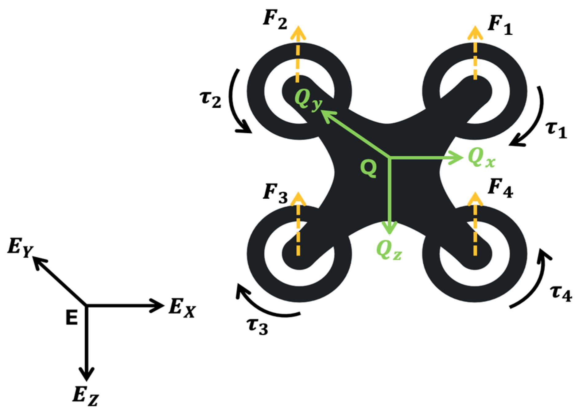
Figure 1 shows the acting forces and torques on the quadrotor. E and Q denote the fixed earth and quadcopter coordinate systems, respectively. Depending on these forces and thrusts, the quadrotor makes translational movements in the x, y, and z directions and rotational movements around these axes called yaw (), pitch (), and roll ().
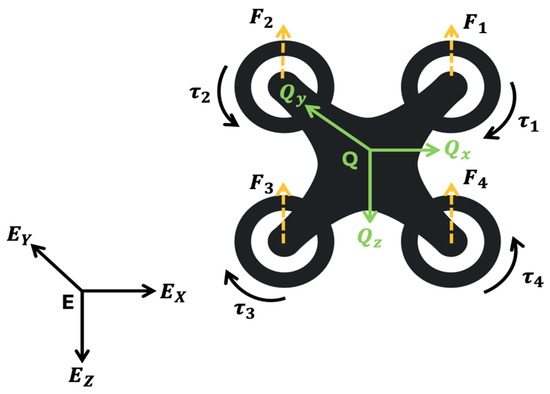
Figure 1.
The forces and torques acting on the quadcopter.
First, the transition matrix is calculated for converting the positions from the earth coordinate (X, Y, Z) system to positions at the quadrotor coordinate system (U, V, W). Equation (1) is used for this conversion [39].
Depending on this translation matrix, the coordinates defined according to the world coordinate system are converted to quadrotor coordinates, and the reference values for quadrotor movement are obtained. There are four control inputs for the quadrotor. Each controller input has an effect on a certain movement. affects the movement in the z direction. It represents the sum of the thrust forces coming from all the motors. The second of these forces, which change depending on the rotation of the quadrotor motors at certain speeds and the drag constant, is , and it controls the roll movement. The third is , which controls the pitch movement, and the fourth is , and the yaw motion is changed depending on it. The relationship between these control forces and rotor angular speeds is shown as follows:
where , , and denote the thrust forces, the angular speeds of the motors, thrust coefficient, and moment coefficient, respectively. The translational motion of the quadcopter describes how its center of mass moves in space. The translational motion equations are shown in Equation (3) [40]
where and denote the aerodynamic thrust drag coefficients along the , , and coordinates, the mass of the quadrotor, and gravitational acceleration, respectively. The rotational dynamics determine the quadcopter’s orientation (roll, pitch, and yaw). These are governed by the Euler equations for rigid body motion. First, the angular velocities at the quadrotor frame are found by using the angular positions, which are found by using Equation (1). The accelerations in the body frame can be derived as follows.
where and are the linear acceleration, and , and denote three angular acceleration components, which are identified in the body reference. After that, the Euler rates () on the fixed earth frame are found by using these angular velocities on the quadrotor frame. The Euler rates are given in Equation (6).
The readers looking for detailed information on modeling can refer to references [39,40,41].
2.2. Modeling of DC/DC Buck Converter
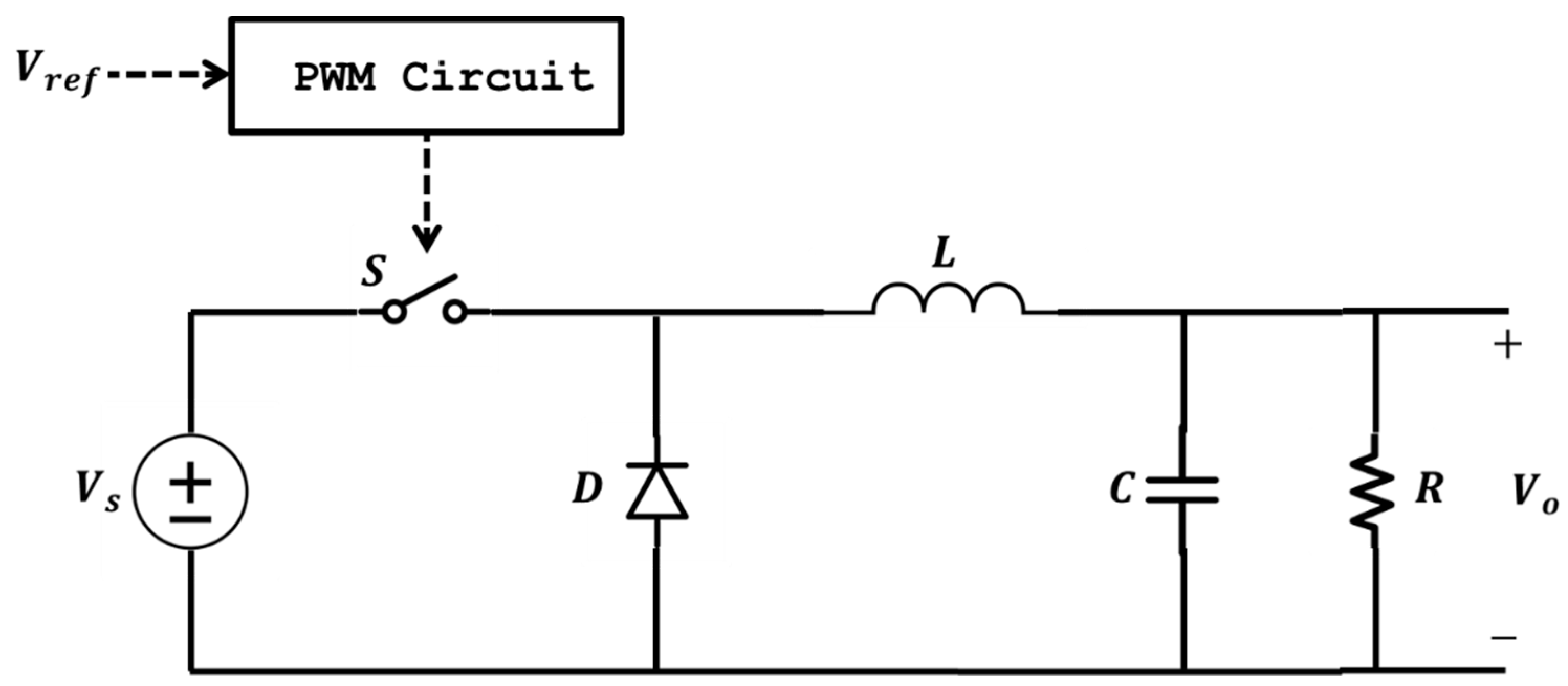
In this study, buck converters were used to reduce the voltage at the fuel cell output to the lower voltage required by the quadrotor motors. DC/DC buck converters are essential in fuel cell systems for regulating the variable output voltage of fuel cells to a stable, lower voltage suitable for different applications. They enhance efficiency, reduce energy losses, and ensure compatibility with various loads, such as batteries, sensors, and controllers. Buck converters also play a vital role in hybrid systems, managing energy flow between fuel cells and energy storage devices like batteries or supercapacitors. The schematic diagram of the DC/DC buck converter is shown in Figure 2. , , and denote the values of resistance, inductance, and capacitance, respectively.
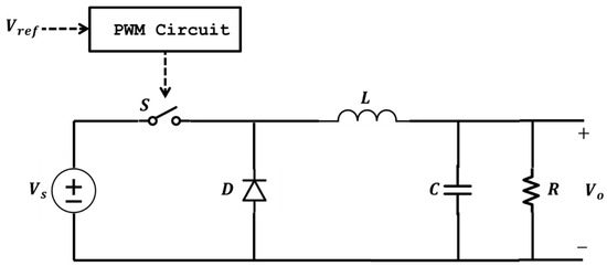
Figure 2.
The electrical circuit of the DC/DC buck converter.
Key applications include automotive systems (e.g., fuel cell electric vehicles), drones (powering motors and avionics), and microgrids (integrating fuel cells with stable voltage output). Their features, such as high efficiency, fast response, and thermal management, make them critical for ensuring reliability and maximizing the potential of fuel cell technology.
2.3. Full Model of Proposed PEMFC-Powered Quadrotor
Our full model consists of a PEM fuel cell, DC/DC power converters, and a quadrotor. Figure 3 shows the full diagram with all the sub-components of the system. The fuel cell was used to provide energy to the quadrotor and was preferred due to the increasing importance of clean energy with developing technologies. The use of hydrogen as fuel is becoming more popular day by day due to the high energy efficiency and low emissions of hydrogen. With the further development of hydrogen technologies, the use of hydrogen as an energy source will increase in the future, and the use of fuel cells in air, land, and sea vehicles will also increase. In this study, the PEM fuel cell model in the MATLAB/Simulink library was used. The features of this model are given in Table 1.
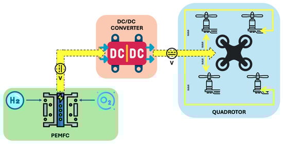
Figure 3.
The diagram of the proposed PEMFC-powered quadrotor system.

Table 1.
Specification of PEM fuel cell [42].
The quadrotor uses 24 V DC motors, and the DC voltage provided by the fuel cell needs to be reduced to these levels. Our motor voltage controllers (PD control), which allow us to adjust the angular speeds of the motors, demand the necessary reference voltage for each motor in the fuel cell. The voltage at the high-voltage fuel cell output is reduced as needed by each motor with the DC/DC buck converters. During this voltage reduction, I controllers are designed to follow the required voltage value. In this way, the voltage at the DC/DC converter output is reduced to the required voltage values to provide the desired quadrotor movement. With these voltages sent to the quadrotor motor, the quadrotor movement is followed, and the desired movement is provided with feedback. The specifications for the DC motor used in this study are given in Table 2 and Table 3.
Table 2.
Specification of BLDC DC motor [43].
Table 3.
The values of the parameters of the DC motor [37].
3. Proposed Methodology
After obtaining the mathematical model of the entire system, the methodology to be applied to save power and increase the route tracking performance was developed. First, the Grey Wolf algorithm to be used in the design of the controllers and converters was emphasized. With this optimization algorithm, the parameters of the PD controllers applied to the control of the speeds of the quadrotor motors for these purposes were determined. Again, for the determined purposes, both the component values and the integral controller parameters of the DC/DC buck converters were realized using this optimization method. For this reason, the optimization technique was first introduced in the following sections, and its application to controllers and converters is shown.
3.1. Grey Wolf Optimization
GWO is inspired by the social hierarchy and hunting behaviors of Grey wolves. Wolves have a hierarchical structure as follows: alpha, beta, delta (subordinate), and omega. Alpha wolves are responsible for decisions such as sleeping places and hunting as leaders, and other wolves accept these decisions by lowering their tails. Beta wolves support the alpha and are strong candidates to take over the leadership role. Delta wolves obey the alpha and beta, while controlling the omega wolves, and include scouts, watchers, hunters, elders, and caretakers. Omega wolves are at the bottom of the hierarchy, play the role of the scapegoat, and maintain social balance by reducing tensions within the group. The GWO algorithm is inspired by this hierarchical structure and the hunting behaviors and performs the optimization process by following the stages of surrounding, hunting, and attacking the prey [44].
GWO plays a key role in energy optimization across different systems. In hybrid fuel cell–battery systems, it dynamically adjusts power allocation to reduce energy losses and enhance efficiency. In renewable energy systems, GWO ensures an optimal balance between supply and demand by configuring energy resources like wind, microbial, and solar [45,46,47]. For drones, it optimizes flight paths and energy usage, improving endurance and minimizing the consumption of hydrogen or batteries. These applications highlight GWO’s versatility in maximizing energy efficiency in diverse technologies. As a result, the GWO algorithm finds widespread application in the energy sector with the aim of increasing energy efficiency and improving system performance. On the other hand, it has proven effective in solving complex, nonlinear optimization problems, making it an ideal choice for energy optimization and controller design in various systems, including robotics, power management, and UAVs.
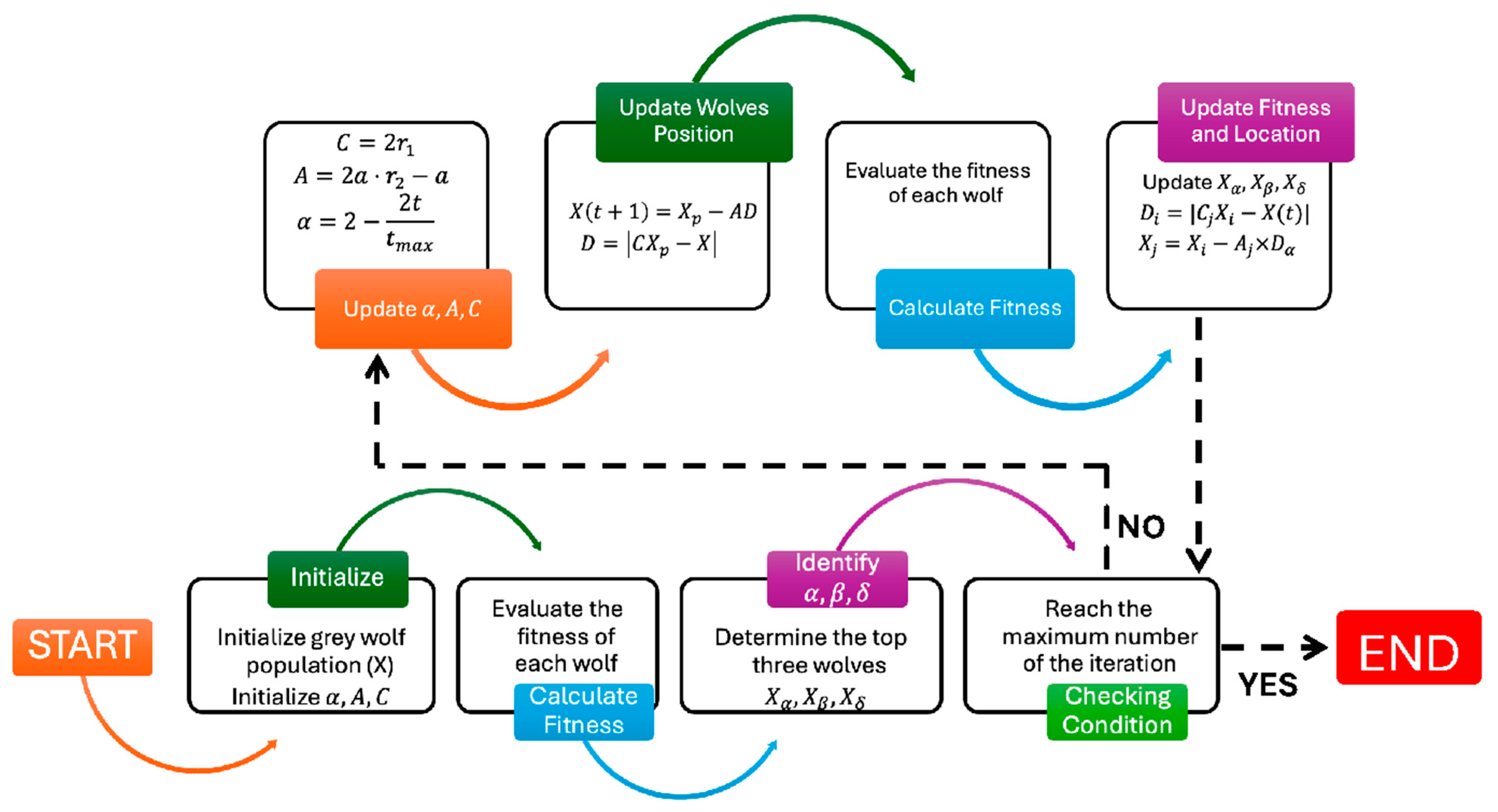
On the other hand, GWO is highly effective in the controller design for various systems. It optimizes PD controllers and other controllers’ parameters by minimizing error metrics, ensuring precise and robust performance. Additionally, it is well suited for multivariable control systems, efficiently optimizing multiple parameters, making it ideal for high-dimensional applications like robotics and UAVs. This versatility underscores GWO’s value in designing advanced and reliable control systems. The algorithm of the GWO is given in Figure 4.

Figure 4.
The steps of the GWO algorithm.
The population is divided into four groups, which are denoted as (best solution), (second best), (third best), and ω (the rest). Initially, a set of candidate solutions is randomly generated. During each iteration, the top three wolves (alpha, beta, and delta) guide the rest of the pack by updating their positions based on a mathematical model of encircling prey. This model involves coefficient vectors A and C, which are influenced by random values and a parameter that linearly decreases from 2 to 0 over time to balance exploration and exploitation. Each wolf updates its position using the average influence of , , and . The process continues until a termination condition is met, such as reaching a maximum number of iterations or achieving a satisfactory fitness level. The best solution found by the wolf is returned as the optimal result.
3.2. Particle Swarm Optimization
PSO is a metaheuristic optimization algorithm inspired by the social behavior of animals in nature and is frequently preferred due to its features such as simplicity, ease of implementation, fast convergence, and success in addressing complex optimization problems. PSO is frequently used to obtain optimum or near-optimum solutions for situations where traditional methods may fail in control and design problems. The basis of PSO is based on a swarm population consisting of candidate solutions called particles and moving in the search space. Information about the current position, speed, best position found so far (pBest), and best position found by the entire swarm (gBest) of the particles is kept, and the position and speed of these particles are updated iteratively and directed to promising regions of the search space to approach the current solution. In the iterative process, the velocity of each particle is updated according to three main factors: inertia, attraction to its personal best position, and attraction to the global best position found by the swarm. The updated velocity then determines the new position of the particle. After each movement, the fitness of the particle is evaluated, and if a better solution is found, pBest and gBest are updated. The algorithm continues this iterative process according to specified criteria, such as the number of iterations, until a predefined termination criterion is met [48]. The algorithm for the searching solution process with PSO is shown in Figure 5.
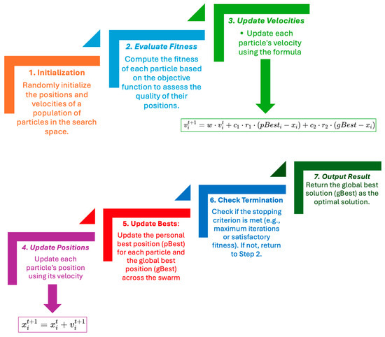
Figure 5.
The steps of the PSO algorithm.
and denote the position and velocity of the particles, respectively. shows the inertia weight, and denotes the cognitive and social coefficients. and are uniform numbers between 0 and 1. This algorithm offers an alternative approach by utilizing a population-based search strategy to explore the parameter space more efficiently. In the literature, control studies using PID-based control for various systems such as DC motors and automatic voltage regulators demonstrate the effectiveness of PSO over traditional tuning methods [49,50].
3.3. Optimization-Based PD Controller
PD controllers are widely used in industrial automation and control systems; however, the performance of these controllers depends on the correct adjustment of the gain parameters (). Traditional methods may be inadequate in determining these parameters or may not produce optimal results. The general equation of PD control is shown in Equation (7).
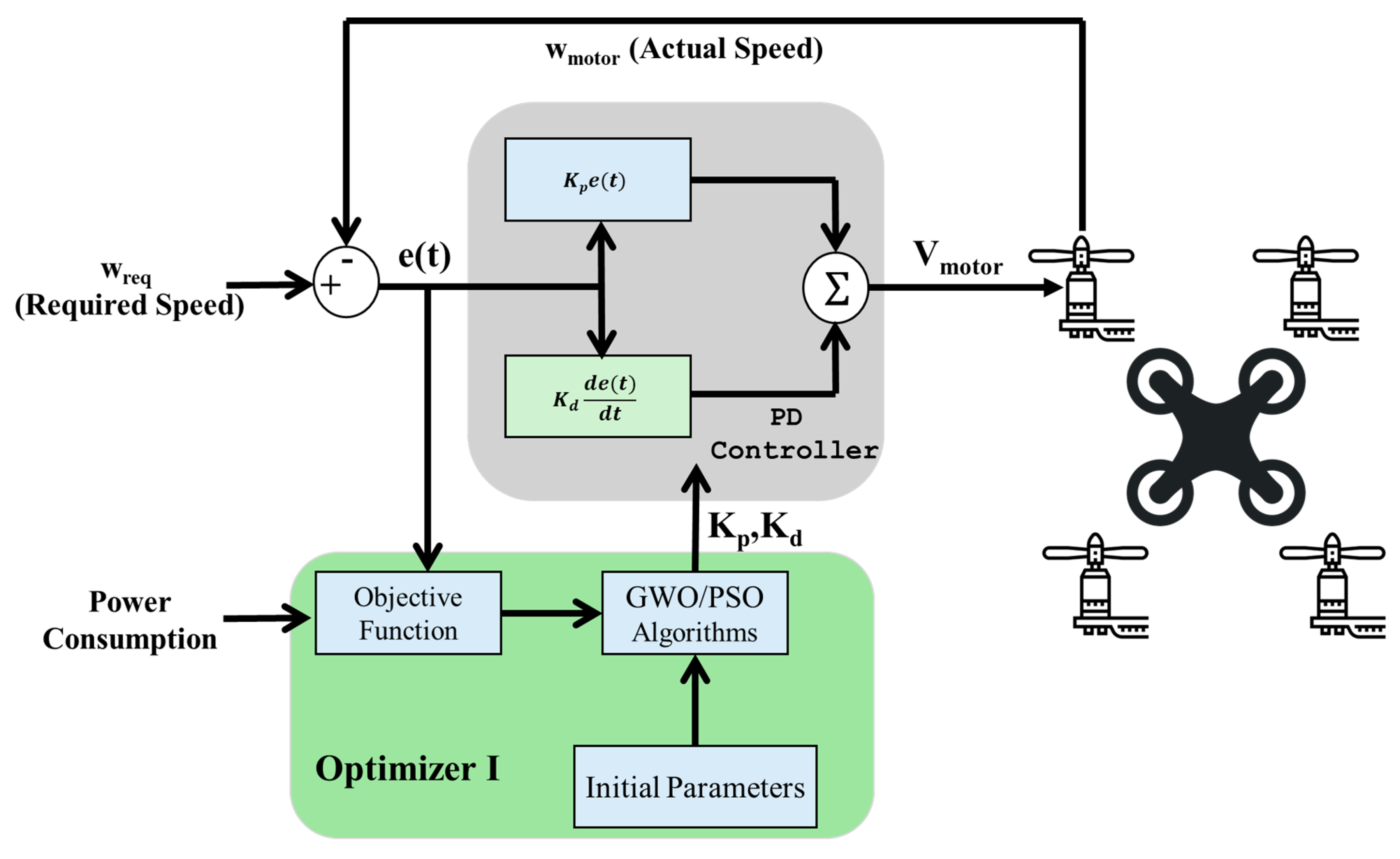
where is the error between the reference value and the actual output value , is the control signal, and are the proportional and derivative gains, respectively. The GWO algorithm provides an effective tool for determining the optimal values of these parameters depending on the attitude/altitude, angular rate (yaw–pitch–roll) values, and the power consumption of the general system. The diagram of the GWO-based PD control of the quadrotor is given in Figure 6.

Figure 6.
The diagram of the GWO/PSO algorithms-based PD controller for each motor.
As shown in the figure, the optimizer is fed by power consumption and the error between the actual speed and the required speed of the motors. The GWO and PSO algorithms decide the optimal values of for minimizing the power consumption and improving the tracking performance of the quadrotor at the same time. The objective function () for minimizing power consumption and the path tracking error is shown in Equation (8). The algorithms iteratively improve these parameters based on a fitness function that evaluates the performances of the controller and converter with the current set of parameters. The algorithm revises its parameters depending on these constraints by using an identified objective function. The integral time absolute error (ITAE) function is used as an objective function because it is one of the most-used criteria to reduce system error and give the best coefficient values for the desired system response requirements. Equation (9) shows the formula for the ITAE function.
where and are weights representing the importance of power consumption and the path tracking error, respectively. and are selected to be 0.5 because both objectives are considered equally important in our problem. denotes the power consumption of the PEM fuel cell. Depending on this method for determining the parameters of the PD controller for each motor, the specific parameters of the GWO and PSO algorithms are given in Table 4 and Table 5.
Table 4.
GWO parameters for optimizing PD controller parameters.
Table 5.
PSO parameters for optimizing PD controller parameters.
The maximum iterations in the optimization algorithms were tested in different ways with values such as 20, 25, 30, and 35. However, as these values increased, the optimization time increased. For smaller iteration numbers, the optimal parameters did not satisfy the successful performance criteria, and since there was no improvement in the results, the number of iterations was decided to be 20.
3.4. Optimization-Based DC/DC Converter Design
Similarly to the PD controller design in the previous section, another aim of this study is to design DC/DC buck converters with maximum energy efficiency and maximum voltage-tracking performance by using GWO and PSO algorithms.
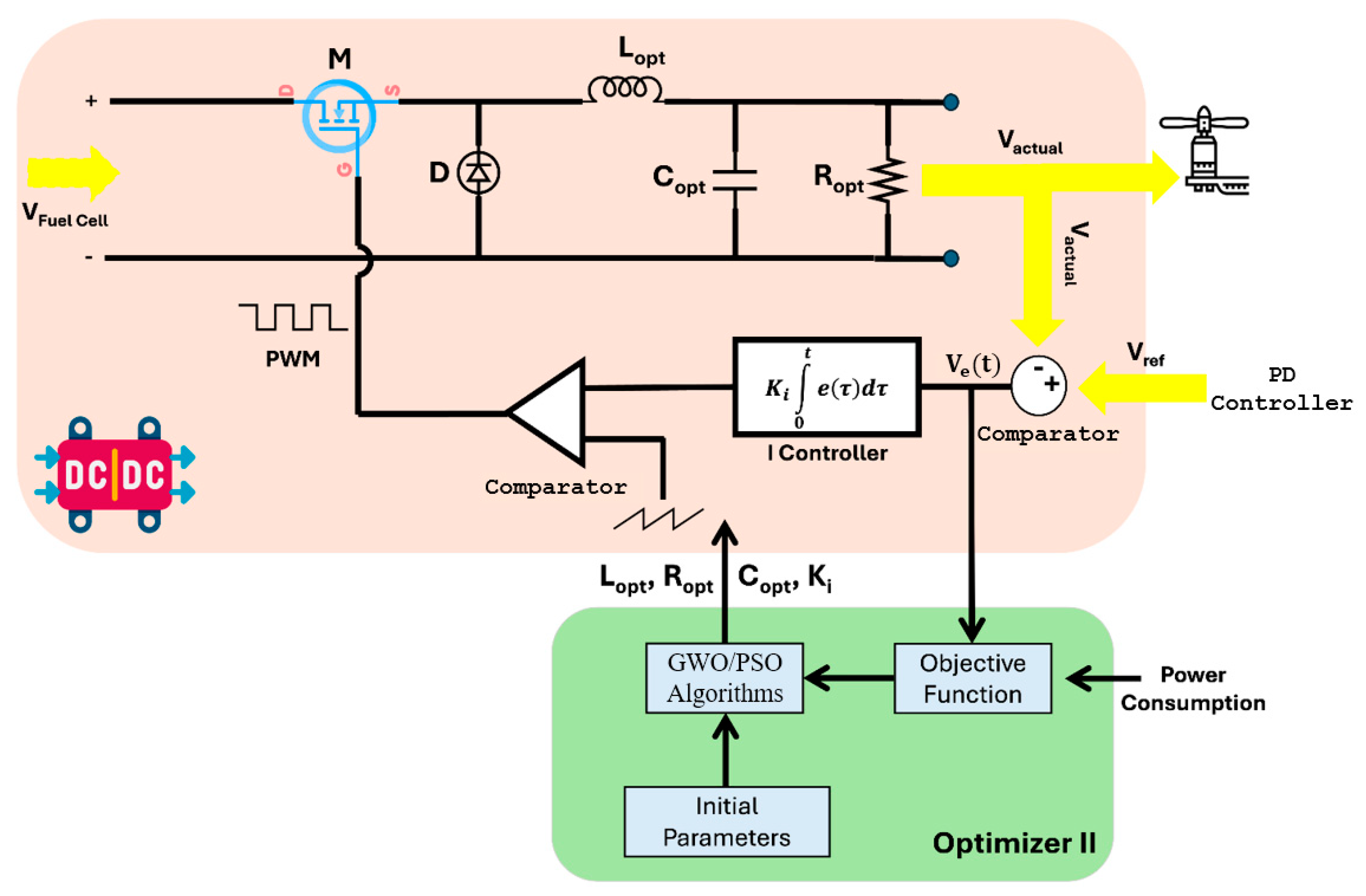
The scheme of the algorithm established for this purpose and its application on the DC/DC converter are shown in Figure 7. It is shown in Figure 6 that the fuel cell feeds the voltage to the DC/DC converter. Then, the DC/DC buck converter reduces these high-voltage values to the required voltage of the quadrotor’s motors. As mentioned before, DC motors operate at a maximum voltage of 12 and provide a torque and angular velocity output according to this voltage input. The required angular velocity output and the voltage value related to it are calculated. This voltage value is fed to the DC/DC converter as a reference voltage, as seen in the figure. This voltage value is compared with the actual voltage value at the output of the converter, and the error is revealed. The resulting error and the amount of power consumed are fed to Optimizer II. The I (Integrator) controller is designed for PWM control. With the designed optimization algorithms, the optimum and values that minimize both the error and the power consumed are determined for each DC/DC converter. The objective function of DC/DC converter design () for minimizing power consumption and the reference/output voltage error, , is shown in Equation (10).
where is the weight, which denotes the importance of the voltage-tracking error at the input and output of the converter, and the is selected to be 0.5. Similarly, the ITAE function in Equation (11) is used as an objective function for this optimizer. GWO and PSO parameters and their optimization intervals for the DC/DC buck converter of each motor are given in Table 6 and Table 7, respectively. Moreover, the switching frequency of the converters is arranged as 10,000 Hz (). This value is good for low-power systems.
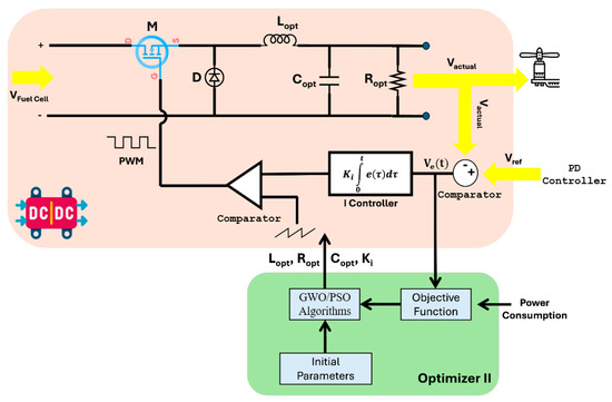
Figure 7.
The diagram of GWO/PDO-based DC/DC buck converter design.
Table 6.
GWO parameters for tuning DC/DC buck converter design parameters.
Table 7.
PSO parameters for tuning DC/DC buck converter design parameters.
4. Simulation Results and Discussion
In this study, the system dynamics for trajectory control is considered as the control of translational, rotational, and angular velocities. The altitude (z) and roll, pitch, and yaw motions (, ) are controlled by the thrust force () and the torques (), respectively. Therefore, the parameters of the four PID controllers, one for the control of the motion at Z axes, three for the control of the roll/pitch/yaw rotations, are adjusted to ensure minimum error and minimum energy consumption by using the GWO and PSO algorithms. The model parameters and their values for the quadrotor are shown in Table 8.
Table 8.
The parameters of the quadrotor.
Firstly, the optimal values for the controllers and DC/DC converters are determined for different paths. The optimizers are tested for different combinations of x, y, and z trajectories and the average values of the PD parameters and the DC/DC converter parameters are used for other test scenarios. By using this test procedure, the optimal values for the PD controllers by using GWO and PSO algorithms are shown in Table 9 and Table 10, respectively.
Table 9.
The determined and values by GWO-based Optimizer I for each altitude and angular rate controller.
Table 10.
The determined and values by PSO-based Optimizer I for each altitude and angular rate controllers.
After applying these algorithms, the values in the table were obtained for the minimum trajectory tracking error and minimum energy consumption. Similarly, the obtained DC/DC converter design and controller parameters are given in Table 11 and Table 12 for GWO- and PSO-based Optimizer II. Especially for electronic equipment, since it is difficult to find resistance, inductance, and capacitance at the values determined, equipment close to these values should be selected in order to minimize the trajectory tracking error, voltage-tracking error, and power consumption. For example, when the table is examined, the circuit design can be made by selecting 60 as the resistance closest to the 58.5593 value given for the first converter. In addition, the equipment can be used in series and parallel connection circumstances to find elements close to these values. These circumstances are valid for R, L, and C equipment.
Table 11.
The determined optimal , , , and values by using GWO-based Optimizer II for each DC/DC buck converter and I controller.
Table 12.
The determined optimal , , and values by using PSO-based Optimizer II for each DC/DC buck converter and I controller.
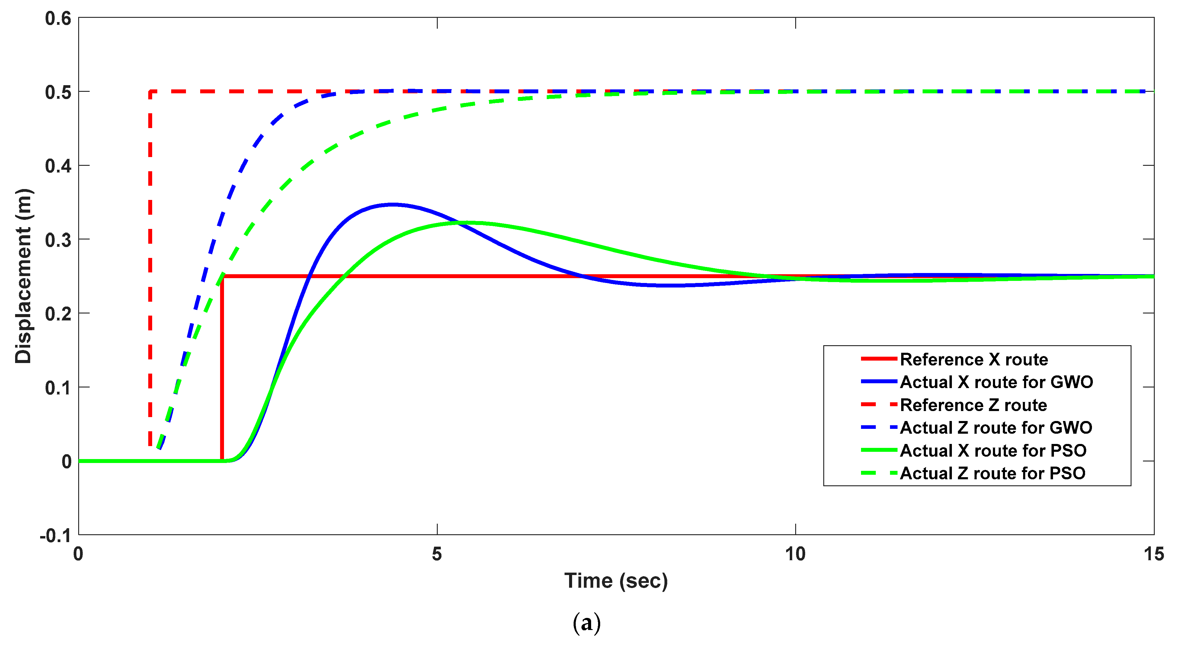
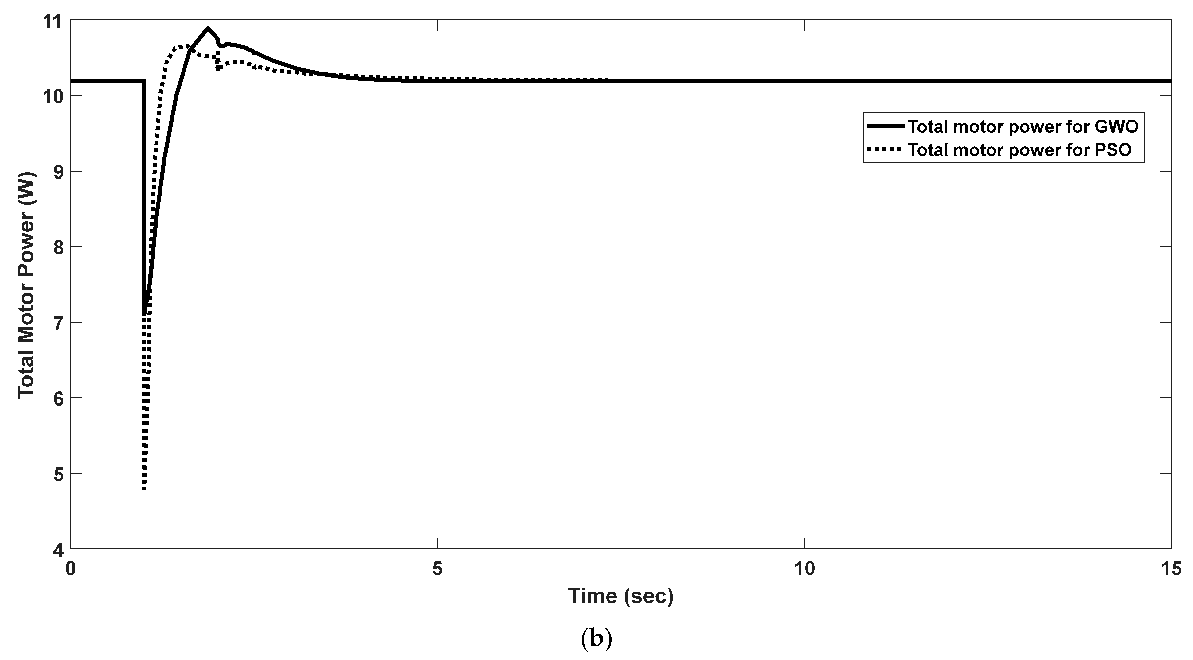
One of the test trajectories used to obtain the data determined by Optimizer I and Optimizer II using the GWO and PSO algorithms is given in Figure 8a. Step reference inputs were applied for the X and Z axes at certain amplitudes in a 15 s simulation. The results show that our quadrotor reaches the desired X and Z values at the end of 15 s successfully. The PSO-based algorithm reaches the desired value later than the GWO-based algorithm. On the other hand, the PSO-based algorithm has a smaller overshoot than the other one. The time domain criteria of the used algorithms during this motion are given in Table 13. It can be observed that the rise time, settling time, and peak time are shorter for GWO-based optimization for both X and Z axis motion. The results show that the values of the parameters do not allow the overshoot at the Z-axis motion, but they lead to overshoot at the X-axis. The GWO algorithm has 24.707% more overshoot than the PSO algorithm. In addition, the total power consumption obtained for this movement is given in Figure 8b. The total power consumptions by motors for this motion at the X and Z axes are 150.4600 W/s and 168.8411 W/s for GWO and PSO, respectively. It can be seen that the power consumption of the motors is smaller when the parameters of the controllers and converters are determined by the GWO algorithm. The GWO algorithm shows 10.8866% less energy consumption than the PSO algorithm for this motion. This means that the algorithms affect the energy and power consumptions of the motors significantly.
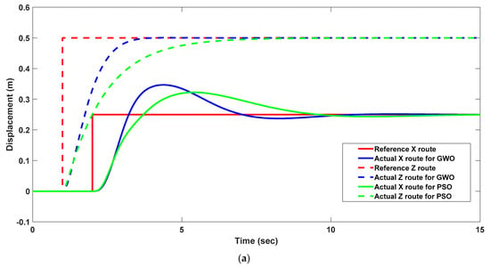
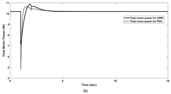
Figure 8.
(a) The X and Z trajectories tracking the performance of the quadrotor. (b) The total power consumption of the motors.
Table 13.
The comparison of time domain criteria for GWO- and PSO-based X and Z trajectory tracking performance.
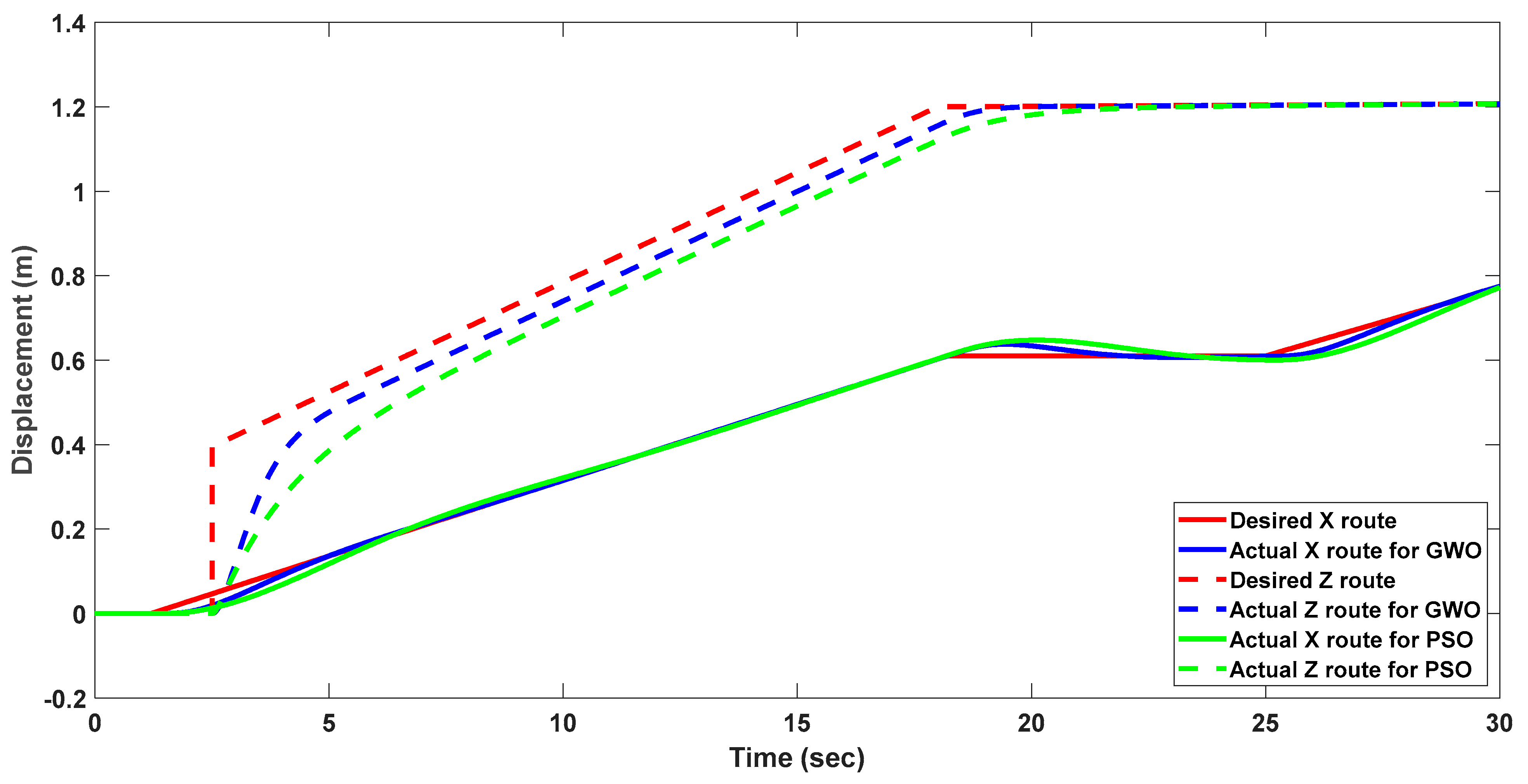
The mean total power consumptions by the motors for this basic motion in Figure 9 are 217.1902 W/s and 264.8288 W/s for GWO and PSO algorithms, respectively. It can be seen that the power consumption of the motors is smaller for the GWO algorithm-based design and control for this motion. This shows that energy saving is approximately 18% for the controller and design values obtained with GWO. It can be seen from both routes that the energy saving performances of these optimization techniques-based controller and converter designs vary depending on the route.
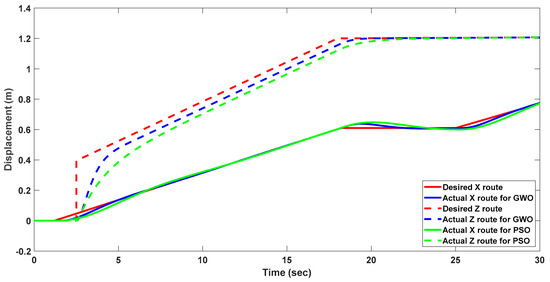
Figure 9.
The X and Z trajectories tracking the performance of the quadrotor for different routes.
Testing Scenario
The performance of the quadrotor was observed for a new test scenario. As a result of this scenario, the tracking performance of the quadcopter is shown after the performance of the controllers and the DC/DC converters by optimizing with Optimizer I and Optimizer II for different trajectories. The energy consumption performances of the fuel cell and the voltage-tracking performances of the DC/DC converters were analyzed during this motion. The new testing scenario is shown in Figure 10.

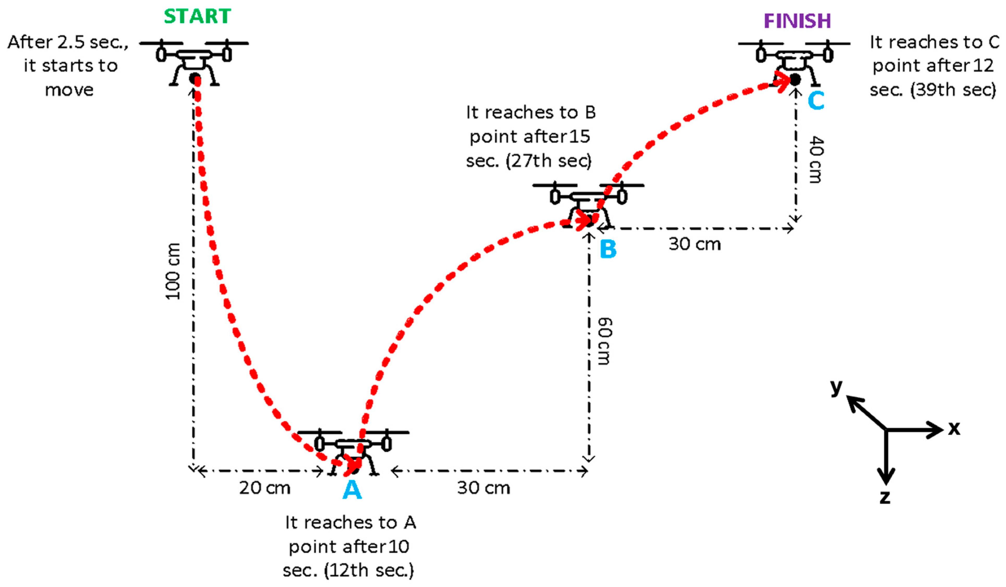
Figure 10.
Testing scenario trajectory at x-y-z coordinates.
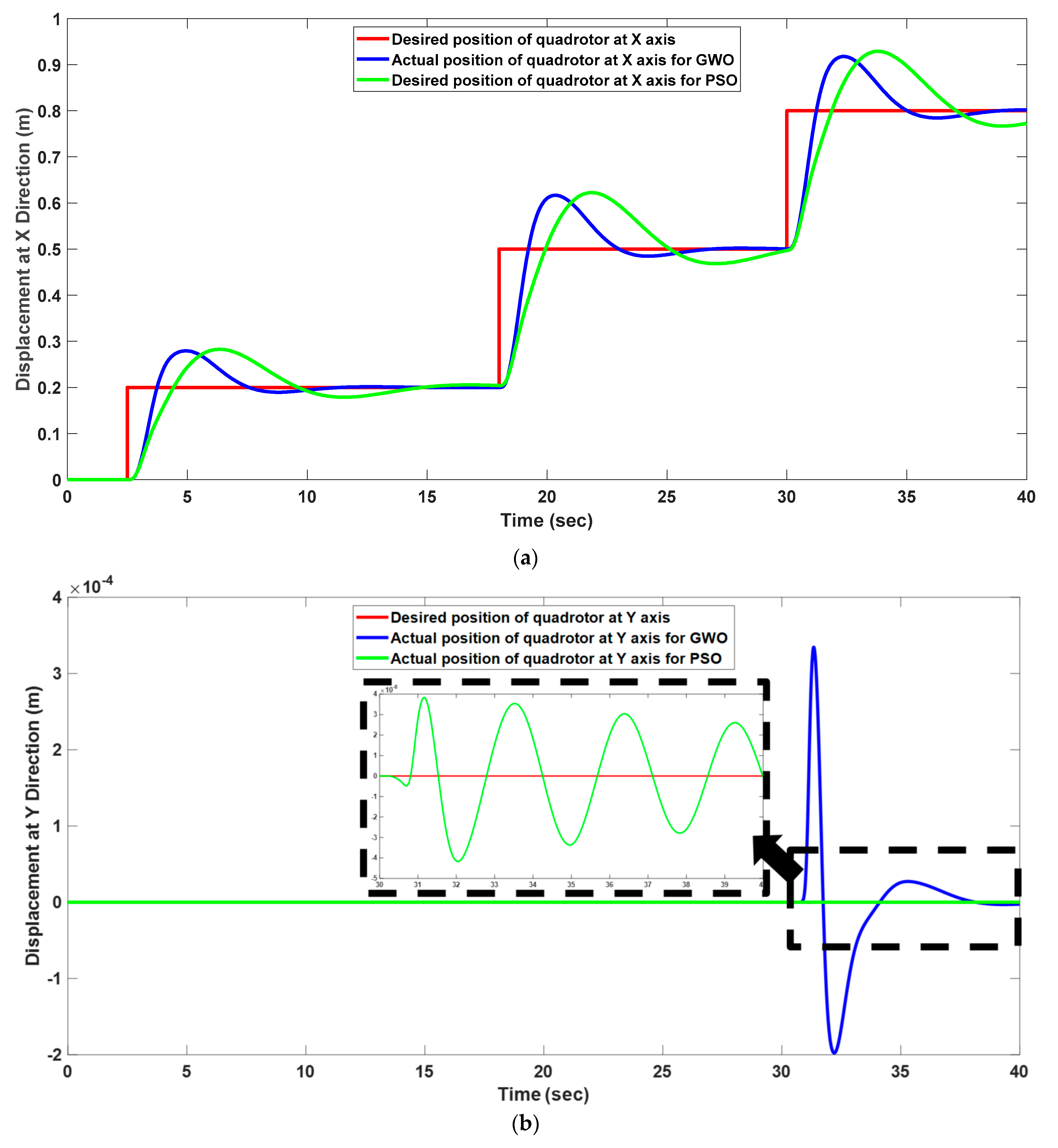
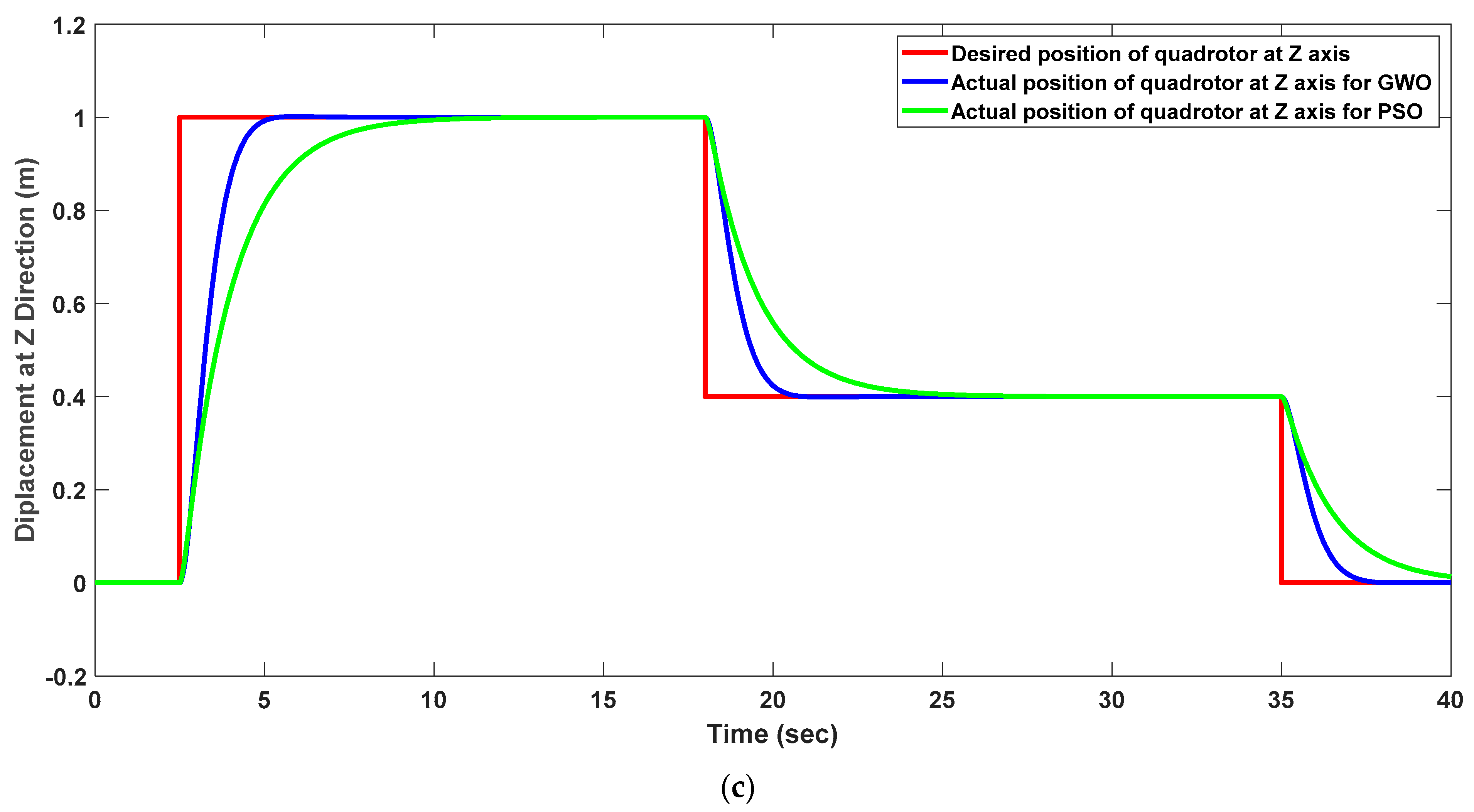
The drone starts to motion at 2.5th seconds, and it tries to reach point A, firstly. Then, it changes its z direction and goes to point B. The drone is at point B approximately 25 s after starting the motion. Then, similar to the previous motion, the drone reaches point C at the end of the motion. The duration of the total motion is 39 s, and the quadrotor moves from A to C during this period. During this scenario, the quadrotor changes its position on the and axes, and the axis motion is always zero. Firstly, the movements of the quadrotor at the , , and axes are analyzed. The tracking performances at these coordinates are shown in Figure 11. Before analyzing the results, it can be mentioned that the quadrotor starts its motion at a 1 m altitude in the direction. The motion in Figure 11c shows that the variation at the axis is positive. This means that the positive motion of the quadrotor is denoted by its downward movement of it.
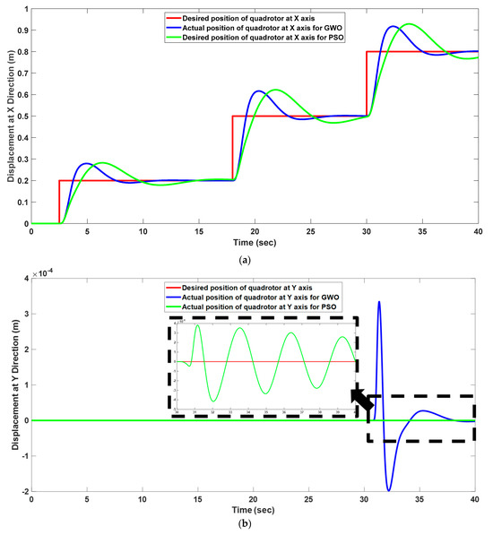
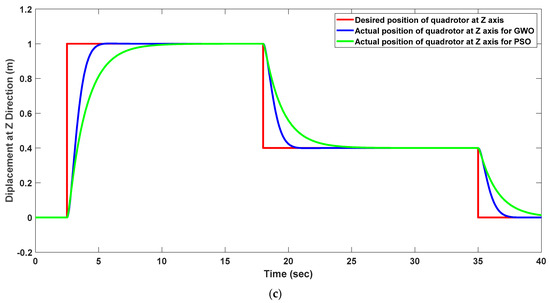
Figure 11.
The tracking performance of the quadrotor at (a) axes, (b) axes, and (c) axes.
It can be seen that the designed optimization-based control strategy shows very successful performances in both frames. The intelligent controller with optimized control coefficients shows better performance in the direction than the direction because it is observed that reaching the reference value in the direction needs more time, and it has an overshoot. We need to allow this overshoot because the other important point for us is energy consumption performance. By using these values, the drone has some overshoots in the x direction, but the energy consumption of the drones is minimized. The total power consumptions during this motion are calculated as 168.0015 W/s and 179.9070 W/s for the GWO and PSO algorithms, respectively. It can be seen that the system with the GWO algorithm-based Optimizer I and Optimizer II shows better energy efficiency and route-tracking performances. The energy consumption of the system becomes 7.0865% less for the GWO-based optimized system than the PSO-based optimized system. This means that a more efficient and stable system is obtained when the GWO algorithm is used.
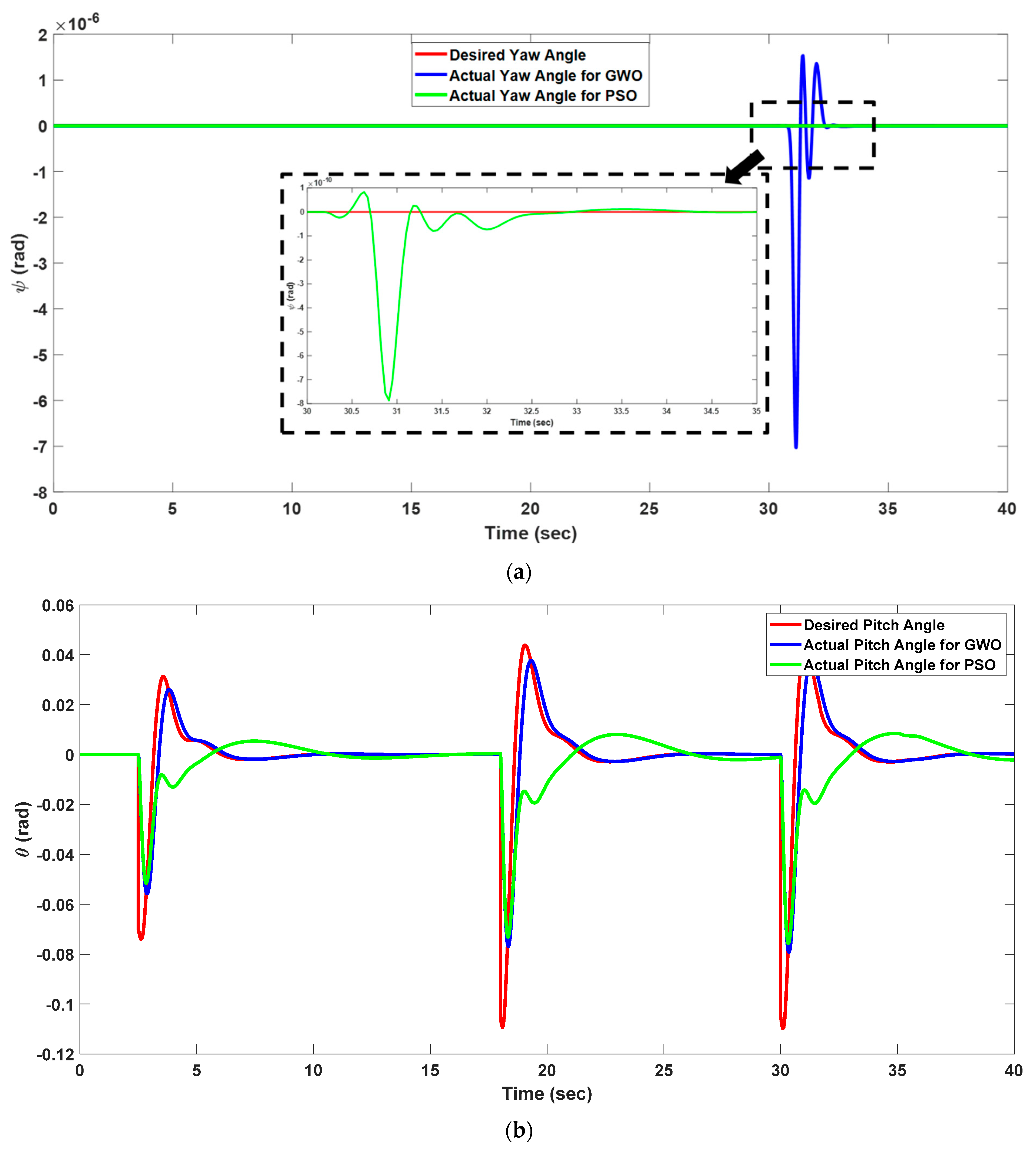
In addition, the angular movements of the quadrotor, such as yaw, pitch, and roll, are of great importance during the movement made. For this route, the quadrotor was given a reference to keep all the angular movement angles at zero. In the quadrotor system, where the altitude, yaw, pitch, and roll angles are generally tried to be kept constant, it is also very important for the system to follow these inputs throughout its movement. The yaw, pitch, and roll movements of the quadrotor are shown in Figure 12.

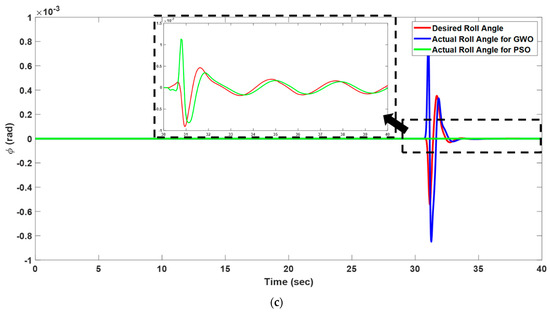
Figure 12.
The angular rates of the quadrotor’s (a) yaw, (b) pitch, and (c) roll.
As seen in the figure, the variations are observed in the angular rates when the quadrotor changes direction in the and directions along its route between different points. Figure 12a shows the yaw motion of the quadrotor, and the reference value of the yaw angle is 0° during this motion. The results show that the yaw angle, , varies at very small angles. Its value changes between rad and rad. This means that the system shows very good performance for controlling the yaw motion. The reference values of the pitch and yaw angle are determined depending on the motion at the and axes. The variation in the pitch angle is shown in Figure 12b. The pitch motion shows a similarly good tracking performance, but the magnitude of the motion along the axis is greater than the other angular motions of the quadrotor. The pitch angle varies between −0.12 rad and 0.06 rad during the motion. The results of the GWO-based optimized system show very good performance for tracking the desired pitch angle. It is seen that the PSO algorithm has difficulty in tracking the reference signal after the decrease in the angle, and the settling time becomes longer in comparison with the GWO algorithm. However, a similar performance was obtained in tracking the roll angle compared to the yaw angle. The overshoot for the PSO algorithm was higher than for GWO. This shows that PSO is more successful in reducing the oscillation along the axis. The sufficient tracking performances between the desired and actual values in both the translational and rotational motion of the quadrotor show the success of the developed optimization-based design of the PEMFC-powered quadrotor system.
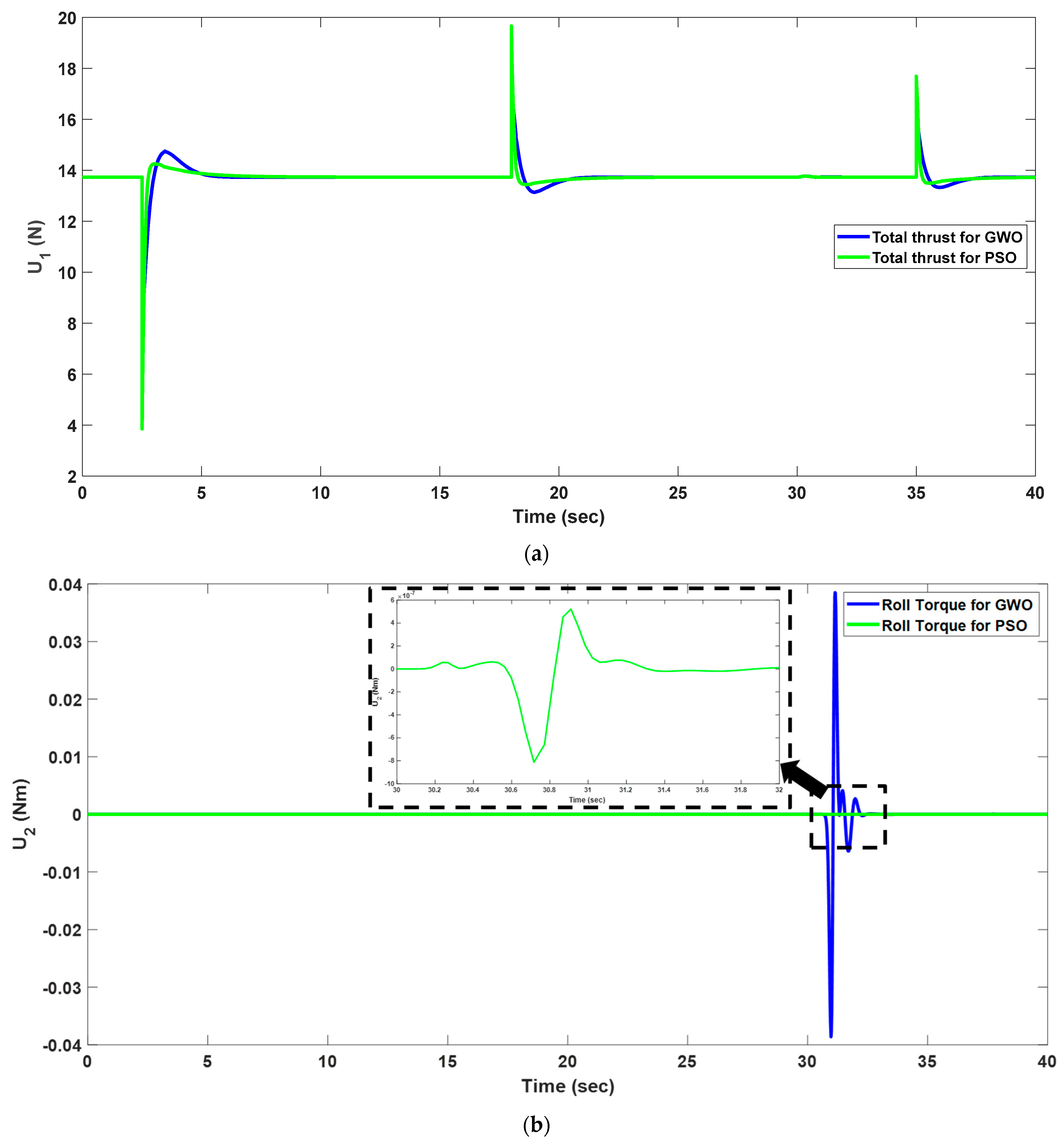
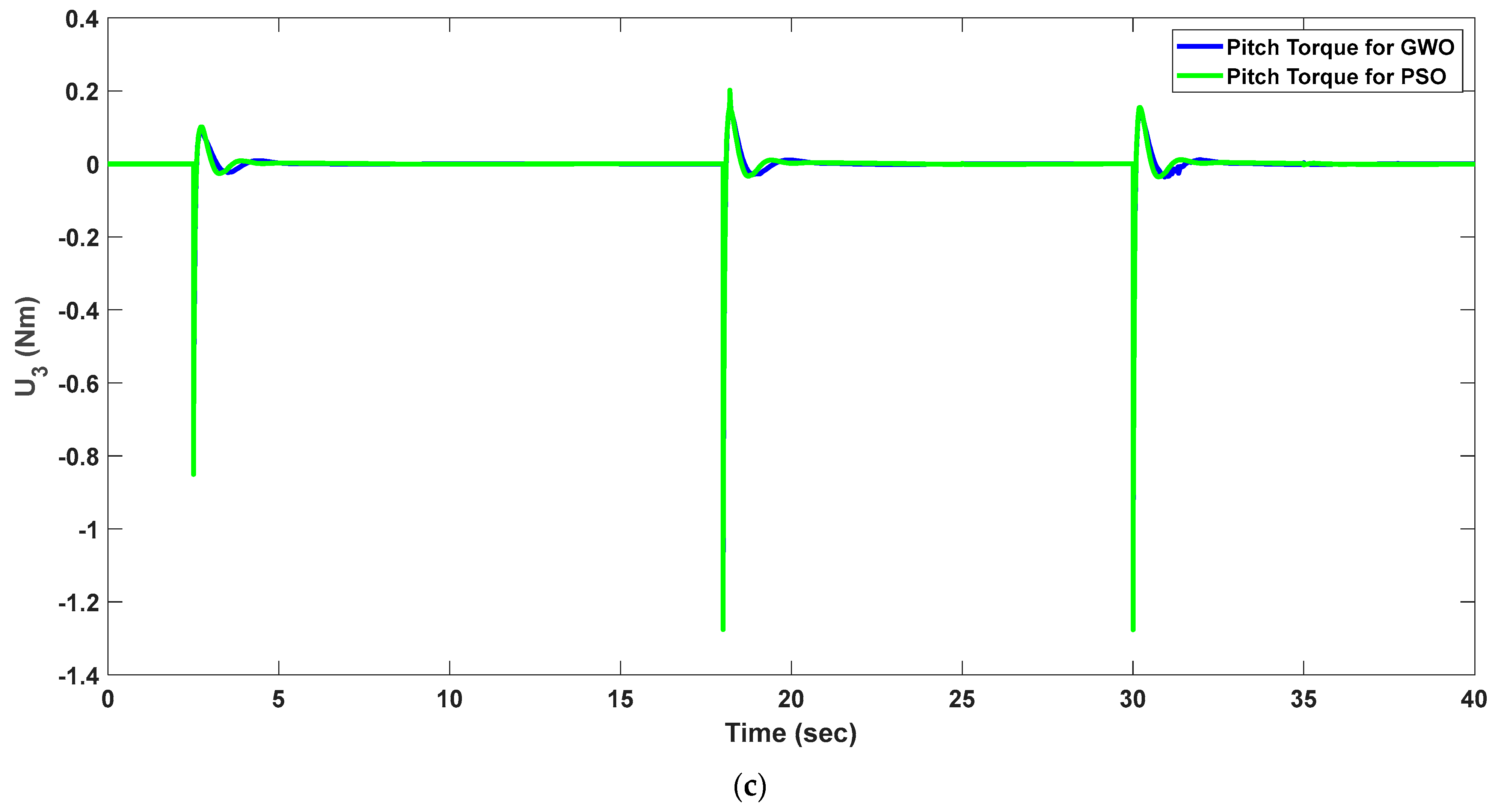
Figure 13 shows the desired thrust force and torques during the motion of the quadrotor. The GWO- and PSO-based optimizers are compared depending on the desired force and torque because these forces and torques ensure that the quadrotor makes the right movements along the specified path. The trust force, which controls the take-off and landing movements along the Z axis, is analyzed in Figure 13a. The results show that the thrust forces are very close to each other for both techniques. However, the GWO-based optimized system has more oscillation after each pick in the total thrust, and PSO shows more stable behavior for the thrust force. Figure 13b shows the variation in the roll torque, , as a function of time for this route for GWO- and PSO-based optimized systems. The comparison shows that the roll torque for the GWO-based optimized system is greater than the PSO-based optimized system. changes between −0.04 Nm and 0.04 Nm for the GWO-based system, but it varies between and for the PSO-based system. This means that the necessary torque is very small in comparison with the first system, and the roll motion is performed with less energy by using the PSO-based optimized system. Similarly, the variation in the pitch torque, , is presented in Figure 13c. It changes between −1.2 Nm and 0.2 Nm during the motion. Similarly to thrust force variation, the picks are observed at certain times, when changes in direction start to begin. The results show that the pitch torques are very close to each other for both optimization techniques.
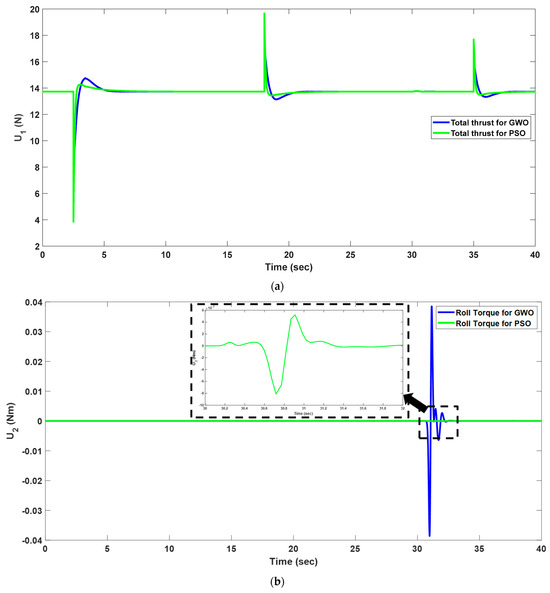
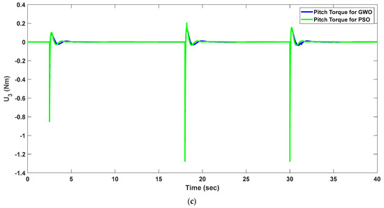
Figure 13.
The comparison of the force and torques for the GWO- and PSO-based optimized systems’ (a) thrust force, (b) control torque of roll motion, and (c) control torque of roll motion.
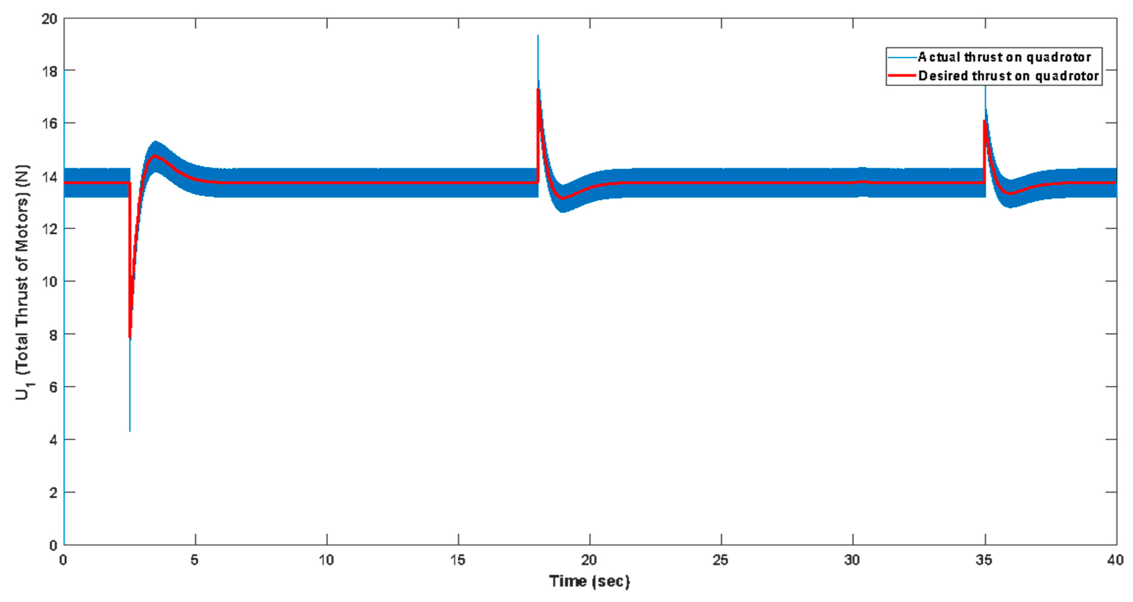
After calculating the required force and torque to obtain the desired movements, the voltages that will create these forces and torques must be fed to the motors. These forces and torques are converted into voltage and fed to the DC/DC buck converters as a reference input by the PD controller. The DC voltage fed from the fuel cell is reduced to the desired voltages by the DC/DC buck converters and fed to the motors to create the necessary thrust force and torques. As mentioned in the above sections, the switching process is performed in the DC/DC buck converter. In this study, the switching frequency is selected as 10,000 Hz (10 KHz). As a result of this switching process, a signal with high oscillation is formed at the converter output, which causes oscillations in the relevant forces and torques. For this reason, it is of great importance to reduce the voltage coming from the fuel cell and reduce it correctly to the level required by the motors. If the required voltages are fed to the motors, then the motors create the required control inputs such as total thrust and other rotational forces.
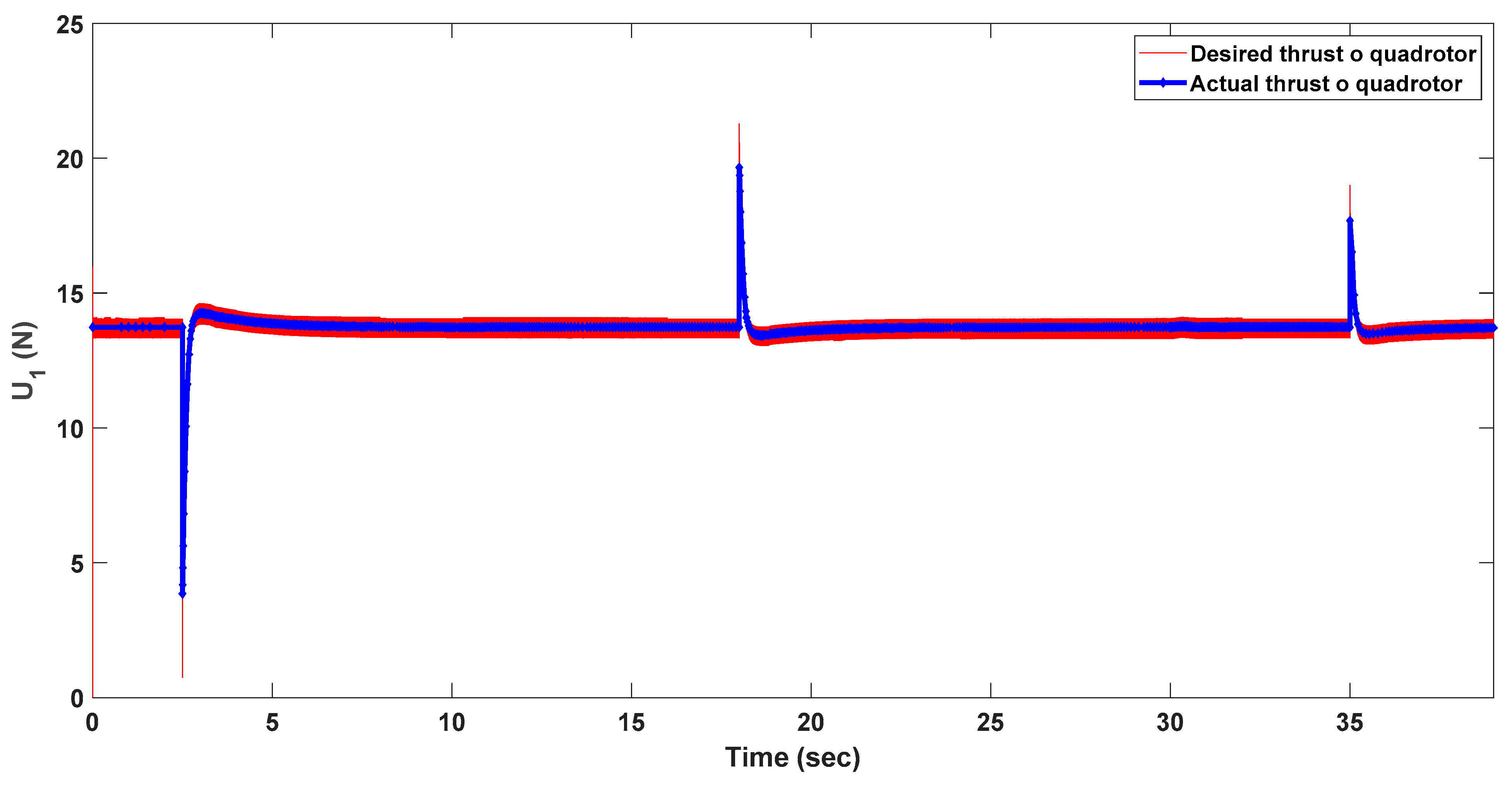
Figure 14 shows the tracking performance between applied desired and actual thrust forces on the quadrotor for the GWO-based optimized system. The results show that the error is less than 1%, and it shows that the GWO-based optimized system shows great performance for tracking the voltage and thrust force. The thrust force required by the motors for the quadrotor is successfully applied with this satisfactory tracking performance.
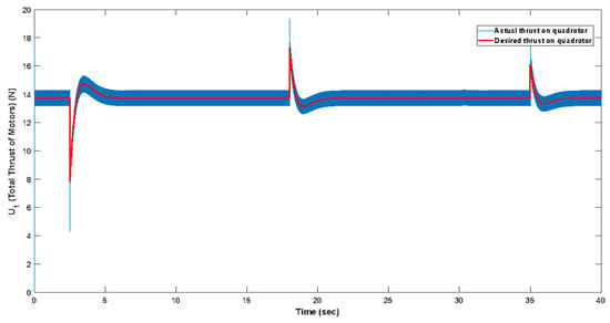
Figure 14.
The comparison of the desired and actual thrust force of the quadrotor for the GWO-based design and control of the DC/DC converter.
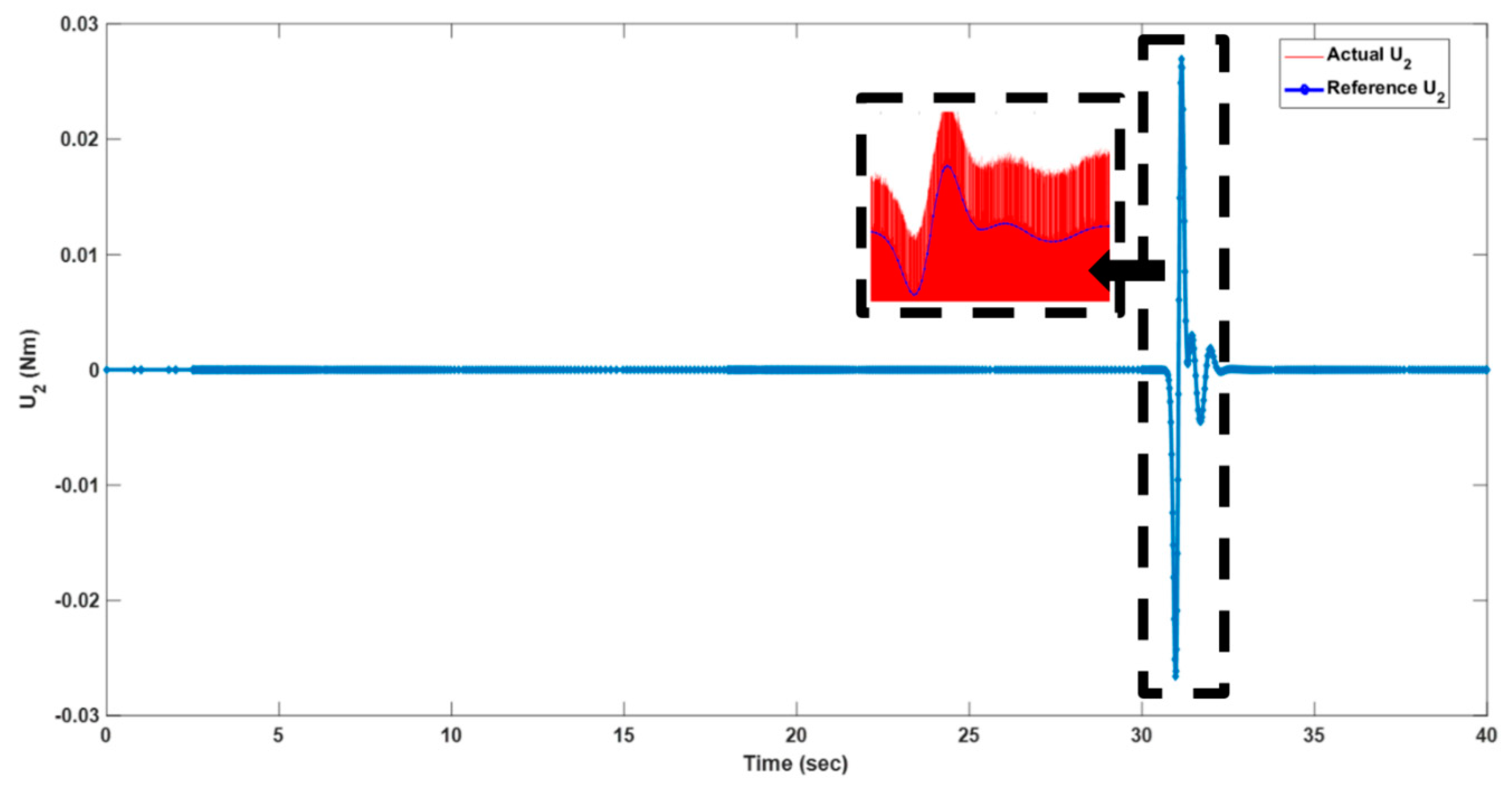
Figure 15 and Figure 16 show the variations in the desired/actual roll and pitch torques as a function of time, respectively. When the tracking performances in both figures are compared, it is seen that the roll and pitch torques are also successfully tracked for the GWO-based optimized system. Similar performance is observed for the yaw torque, but it is not given graphically because its change over time is similar to the roll torque. Accordingly, the GWO-based optimized system exhibits good performance in terms of calculating the necessary forces and torques for maximum route-tracking performance with minimum energy and applying these torques to the quadrotor. The GWO technique has made a very successful determination, while the Optimizer I PD controller calculates the necessary forces and torques, and the Optimizer II DC/DC converters calculate the voltages that will create the necessary forces and torques after determining the I controller and component values.

Figure 15.
The variation in the desired and actual output torques for the GWO-based design and control of the DC/DC converter during the roll motion of the quadrotor.
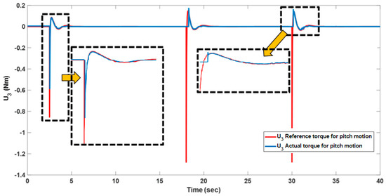
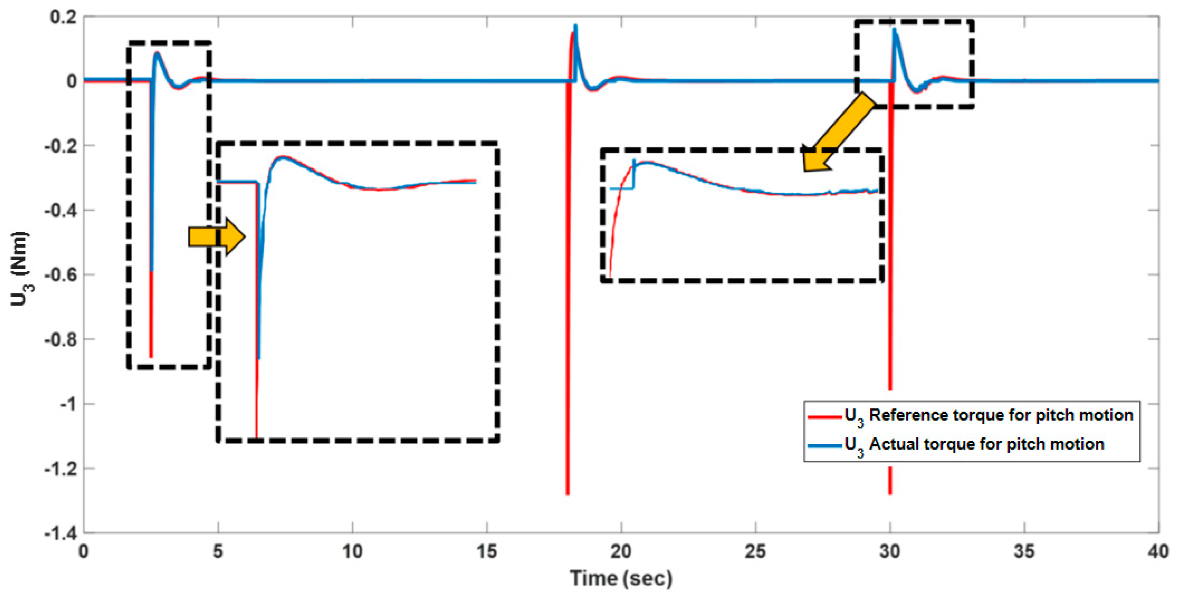
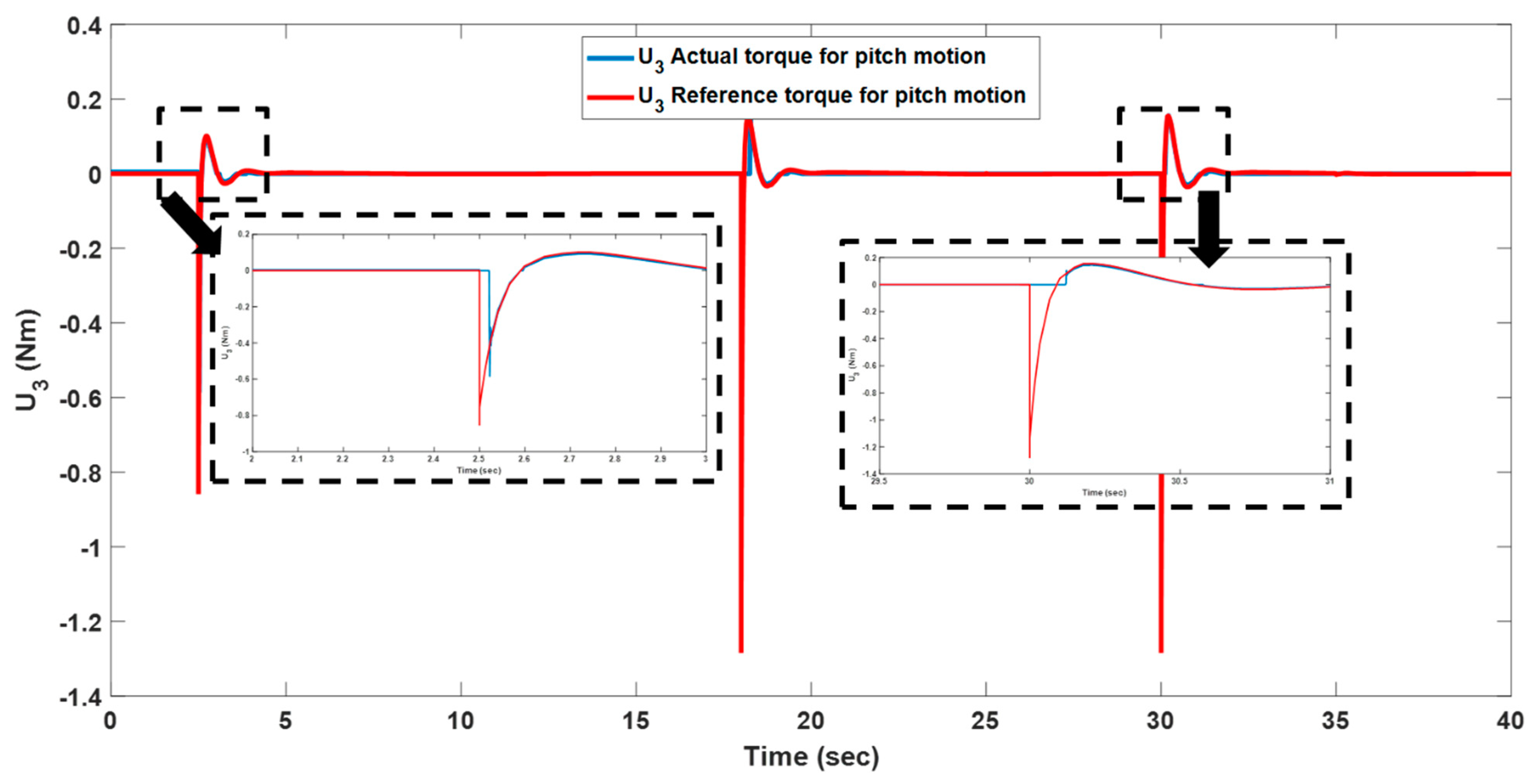
Figure 16.
The variation in the desired and actual output torques for the GWO-based design and control of the DC/DC converter during the pitch motion of the quadrotor.
After that, the thrust force- and torque-tracking performances are investigated for the PSO-based optimized system. Figure 17 and Figure 18 show the thrust force variation and pitch torque variation for the desired and actual values. Only thrust force and pitch torque graphs are given for the PSO-based optimized system because similar tracking performance was achieved with the GWO-based optimized systems. This shows that Optimizer I and Optimizer II in the PSO-based optimized system successfully tuned the controller parameters and the DC/DC converter component values, such as in the GWO-based optimized system. With this successful determination process, maximum route tracking was achieved with minimum energy consumption by the PSO algorithm-based optimizers.
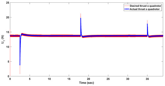
Figure 17.
The comparison of the desired and actual thrust force of the quadrotor for the PSO-based design and control of the DC/DC converter.
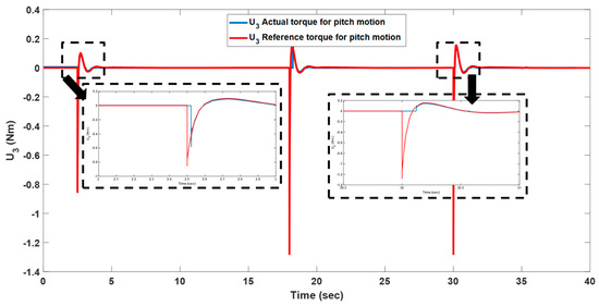
Figure 18.
The variation in the desired and actual output torques for the PSO-based design and control of the DC/DC converter during the pitch motion of the quadrotor.
5. Conclusions
In recent years, the use of alternative energy sources has increased in aviation and in all sectors. The use of hydrogen as fuel, which is one of the sources with cleaner emissions and high-energy efficiency, has become a necessity for air vehicles as well as land and sea vehicles. Vehicles such as drones used in aviation can also be supported by alternative energy sources due to cost, environmental, and time advantages in order to travel longer distances in a cleaner way. In this study, GWO and PSO algorithms-based designs are developed for optimizing the energy efficiency and route-tracking performances of the PEMFC-powered quadrotor simultaneously. This paper extends the work of the other papers by considering voltage transmitting into FC, DC/DC converter, and quadrotor systems and using metaheuristic techniques for optimizing the designs of the controllers and system components. Two optimizers are designed for the full system, which consists of the PEM FC, DC/DC buck converter, and quadrotor system. Optimizer I is used for optimizing the PD controller to minimize the route-tracking error, and Optimizer II is used for controlling the DC/DC buck converter’s controller parameters and the values of its components. Both optimizers work together in the system and try to minimize tracking errors and power consumption simultaneously. Tests were performed for different routes and energy consumption, route-following performance, errors for translational–rotational movements, thrust force, and torque errors produced by the engines were analyzed for the GWO-based optimized system and the PSO-based optimized system. Each subsystem output was analyzed, and the desired output effect was compared with the current output effect. At the end of this study, the following conclusions were reached.
- The use of metaheuristic techniques to design controllers and DC/DC converters with high energy efficiency and route-tracking performance gives successful results.
- The GWO-based optimized system generally provides more power savings for all routes.
- It is observed that the GWO-based optimized system provides 10% to 25% more energy savings for the three different routes tested. It is observed that this energy saving performance varies according to the complexity of the route.
- The overshoot is less for the parameters in the PSO-based optimized system. However, it is observed that time domain criteria such as the rise time, settling time, and peak time are longer compared to the system optimized with the other algorithm.
- It is seen that the desired X, Y, and Z and yaw, pitch, and roll movements for successful route tracking are successfully followed by using the values obtained with both optimizers simultaneously. After the error analysis, it is seen that tracking errors between 0% and 10% occur for GWO and PSO in translation and rotation movement tracking depending on the given routes. For routes that require smoother movements, this error value approaches 0%.
- It is observed that the errors between the actual and desired values of the thrust force and torques required to be generated by the engines in both systems are very small. This error has been observed as a maximum of 4% under some conditions. This shows that both optimizers perform sufficiently with necessary voltage regulation success.
According to these results, it is seen that the hydrogen-fueled quadrotor designed with the developed controllers is suitable for longer operations with high energy efficiency and high route-tracking performance in sectors such as transportation, cargo, and defense. In future studies, the results of this simulation study can be proven with experimental tests for the FCQuadrotor system, and discussions can be made on the effect of the optimization results using different optimization algorithms.
Funding
This research received no external funding.
Data Availability Statement
The dataset is available on request from the authors.
Conflicts of Interest
The author declares no conflict of interest.
References
- İnci, M.; Büyük, M.; Demir, M.H.; İlbey, G. A review and research on fuel cell electric vehicles: Topologies, power electronic converters, energy management methods, technical challenges, marketing and future aspects. Renew. Sustain. Energy Rev. 2021, 137, 110648. [Google Scholar] [CrossRef]
- Necula, S. Assessing the Potential of Artificial Intelligence in Advancing Clean Energy Technologies in Europe: A Systematic Review. Energies 2023, 16, 7633. [Google Scholar] [CrossRef]
- Anselma, P.G.; Belingardi, G. Fuel cell electrified propulsion systems for long-haul heavy-duty trucks: Present and future cost-oriented sizing. Appl. Energy 2022, 321, 119354. [Google Scholar] [CrossRef]
- Demir, M.H.; Demirok, M. Designs of Particle-Swarm-Optimization-Based Intelligent PID Controllers and DC/DC Buck Converters for PEM Fuel-Cell-Powered Four-Wheeled Automated Guided Vehicle. Appl. Sci. 2023, 13, 2919. [Google Scholar] [CrossRef]
- Gallo, M.; Mario, M. The Impact of Fuel Cell Electric Freight Vehicles on Fuel Consumption and CO2 Emissions: The Case of Italy. Sustainability 2022, 14, 13455. [Google Scholar] [CrossRef]
- Mu, Z.; Fuquan, Z.; Fanlong, B.; Zongwei, L.; Han, H. Evaluating Fuel Cell vs. Battery Electric Trucks: Economic Perspectives in Alignment with China’s Carbon Neutrality Target. Sustainability 2024, 16, 2427. [Google Scholar] [CrossRef]
- Rahman, T.; Miah, M.S.; Karim, T.F.; Hossain Lipu, M.S.; Fuad, A.M.; Islam, Z.U.; Ali MM, N.; Shakib, M.N.; Sahrani, S.; Sarker, M.R. Empowering Fuel Cell Electric Vehicles Towards Sustainable Transportation: An Analytical Assessment, Emerging Energy Management, Key Issues, and Future Research Opportunities. World Electr. Veh. J. 2024, 15, 484. [Google Scholar] [CrossRef]
- Huang, X.; Song, K.; Huang, L.; Feng, Y.; Wang, Z. Performance Analysis of Fuel Cells for High Altitude Long Flight Multi-rotor Drones; SAE Technical Papers; SAE International: Warrendale, PA, USA, 2024. [Google Scholar] [CrossRef]
- Boukoberine, M.N.; Donateo, T.; Benbouzid, M. Optimized Energy Management Strategy for Hybrid Fuel Cell Powered Drones in Persistent Missions Using Real Flight Test Data. IEEE Trans. Energy Convers. 2022, 37, 2080–2091. [Google Scholar] [CrossRef]
- Kim, Y.; Kang, S. Development of optimal energy management strategy for proton exchange membrane fuel cell-battery hybrid system for drone propulsion. Appl. Therm. Eng. 2025, 258, 124646. [Google Scholar] [CrossRef]
- Alzyod, M.N.; Al-Awami, A.T.; Jeong, Y.; Kim, S. A Multi-Phase Energy Management System for Hybrid Fuel Cell Drones. In Proceedings of the 2024 IEEE Transportation Electrification Conference and Expo, ITEC 2024, Chicago, IL, USA, 19–21 June 2024. [Google Scholar] [CrossRef]
- Gavrilovic, N.; Leng, Y.; Moschetta, J.-M. Thermal control of a hydrogen-powered uncrewed aerial vehicle for crossing the Atlantic Ocean. Aerosp. Sci. Technol. 2024, 155, 109667. [Google Scholar] [CrossRef]
- MarquÃs, R.; Montero, Ã.; SÃnchez-Diaz, C.; Quintanilla, I. Design methodology and simulation analysis of hybrid fuel cell and battery systems for powering unmanned aircraft systems. Energy Convers. Manag. 2024, 306, 118303. [Google Scholar] [CrossRef]
- Zakhvatkin, L.; Schechter, A.; Buri, E.; Avrahami, I. Edge Cooling of a Fuel Cell during Aerial Missions by Ambient Air. Micromachines 2021, 12, 1432. [Google Scholar] [CrossRef]
- Hassan, A.A.; El Habrouk, M.; Deghedie, S. Renewable Energy for Robots and Robots for Renewable Energy—A Review. Robotica 2020, 38, 1576–1604. [Google Scholar] [CrossRef]
- Belmonte, N.; Staulo, S.; Fiorot, S.; Luetto, C.; Rizzi, P.; Baricco, M. Fuel cell powered octocopter for inspection of mobile cranes: Design, cost analysis and environmental impacts. Appl. Energy 2018, 215, 556–565. [Google Scholar] [CrossRef]
- Zakhvatkin, L.; Schechter, A.; Avrahami, I. Water Recuperation from Hydrogen Fuel Cell during Aerial Mission. Energies 2022, 15, 6848. [Google Scholar] [CrossRef]
- Sood, K.; Mahto, R.; Shah, H.; Murrell, A. Power Management of Autonomous Drones using Machine Learning. In Proceedings of the 2021 IEEE Conference on Technologies for Sustainability, SusTech 2021, Virtual, 22–24 April 2021; p. 9467475. [Google Scholar] [CrossRef]
- Prajapati, S.; Charulatha, S. Design of a PEM fuel cell powered autonomous quadcopter. Int. J.Model. Identif. Control 2023, 42, 271–286. [Google Scholar] [CrossRef]
- Ren, X.; Fan, H.; Ma, M.; Fan, H.; Yue, L. Time-dependent hydrogen fuel cell vehicle routing problem with drones and variable drone speeds. Comput. Ind. Eng. 2024, 193, 110330. [Google Scholar] [CrossRef]
- Oh, J.; Hyun, D.; Park, S.; Han, J. PEMFC Response Characteristics of Drones for Pesticide Spraying Using a Dynamic Model. Trans. Korean Soc. Mech.Eng. B 2023, 47, 339–346. [Google Scholar] [CrossRef]
- Apeland, J.; Pavlou, D.G.; Hemmingsen, T. Sensitivity Study of Design Parameters for a Fuel Cell Powered Multirotor Drone. J. Intell. Robot.Syst. Theory Appl. 2021, 102, 6. [Google Scholar] [CrossRef]
- Hyun, D.; Han, J.; Hong, S. Development of hybrid-powered, sustainable multi-purpose drone system: An analysis model. Int. J. Hydrogen Energy 2024, 61, 762–773. [Google Scholar] [CrossRef]
- Hyun, D.; Han, J.; Hong, S. Power Management Strategy of Hybrid Fuel Cell Drones for Flight Performance Improvement Based on Various Algorithms. Energies 2023, 16, 8001. [Google Scholar] [CrossRef]
- Apeland, J.; Pavlou, D.; Hemmingsen, T. Suitability analysis of implementing a fuel cell on a multirotor drone. J. Aerosp. Technol. Manag. 2020, 12, e3220. [Google Scholar] [CrossRef]
- Chia, A.F.Y.; Min, K.M. Design and Performance Analysis of a Fuel Cell Powered Heavy-Lift Multirotor Drone. Lect. Notes Electr. Eng. 2023, 912, 269–282. [Google Scholar] [CrossRef]
- Kim, D.H.; Lim, J.-H.; Lim, J.-Y.; Lee, B.K. Active Current Sharing and Source Management Methods on Fuel Cell/Battery Hybrid System for Drones with High Power Density. In Proceedings of the Conference Proceedings—IEEE Applied Power Electronics Conference and Exposition—APEC 2024, Long Beach, CA, USA, 25–29 February 2024; pp. 256–259. [Google Scholar] [CrossRef]
- Boukoberine, M.N.; Zia, M.F.; Benbouzid, M.; Zhou, Z.; Donateo, T. Hybrid fuel cell powered drones energy management strategy improvement and hydrogen saving using real flight test data. Energy Convers. Manag. 2021, 236, 113987. [Google Scholar] [CrossRef]
- Wang, J.; Jia, R.; Liang, J.; She, C.; Xu, Y.-P. Evaluation of a small drone performance using fuel cell and battery; Constraint and mission analyzes. Energy Rep. 2021, 7, 9108–9121. [Google Scholar] [CrossRef]
- Shen, Z.; Liu, S.; Zhu, W.; Ren, D.; Xu, Q.; Feng, Y. A Review on Key Technologies and Developments of Hydrogen Fuel Cell Multi-Rotor Drones. Energies 2024, 17, 4193. [Google Scholar] [CrossRef]
- Day, B.; Pourmovahe, A. Review of latest developments in pem fuel cell research with application to hydrogen powered drones. Renew. Energy Power Qual. J. 2021, 19, 7–11. [Google Scholar] [CrossRef]
- Dube, A.; Patil, O.; Singh, G.; Gopalan, N.; Vrudhula, S. Hardware-software co-design for path planning by drones. In Proceedings of the 2024 IEEE/RSJ International Conference on Intelligent Robots and Systems (IROS), Abu Dhabi, United Arab Emirates, 14–18 October 2024; pp. 8141–8146. [Google Scholar] [CrossRef]
- Saeed, R.A.; Omri, M.; Abdel-Khalek, S.; Ali, E.S.; Alotaibi, M.F. Optimal path planning for drones based on swarm intelligence algorithm. Neural Comput. Applic 2022, 34, 10133–10155. [Google Scholar] [CrossRef]
- Pasha, J.; Elmi, Z.; Purkayastha, S.; Fathollahi-Fard, A.M.; Ge, Y.; Lau, Y. The drone scheduling problem: A systematic state-of-the-art review. IEEE Trans. Intell. Transp. Syst. 2022, 23, 14224–14247. [Google Scholar] [CrossRef]
- Benotsmane, R.; Vásárhelyi, J. Towards optimization of energy consumption of tello quad-rotor with mpc model im-plementation. Energies 2022, 15, 9207. [Google Scholar] [CrossRef]
- Lin, L.; Wang, Z.; Tian, L.; Wu, J.; Wu, W. A PSO-based energy-efficient data collection optimization algorithm for UAV mission planning. PLoS ONE 2024, 19, e0297066. [Google Scholar] [CrossRef] [PubMed]
- Trihinas, D.; Agathocleous, M.; Avogian, K.; Katakis, I. FlockAI: A testing suite for ml-driven drone applications. Future Internet 2021, 13, 317. [Google Scholar] [CrossRef]
- Bousbaine, A.; Wu, M.H.; Poyi, G.T. Modeling and Simulation of a Quad-Rotor Helicopter; University of Derby: Derby, UK, 2014. [Google Scholar]
- Iyer, A.; Bansal, H.O. Modelling, Simulation, and Implementation of PID Controller on Quadrotors. In Proceedings of the 2021 International Conference on Computer Communication and Informatics (ICCCI), Coimbatore, India, 27–29 January 2021; pp. 1–7. [Google Scholar]
- Islam, M.; Okasha, M.; Idres, M.M. Dynamics and Control Of Quadcopter Using Linear Model Predictive Control Approach. IOP Conf.Ser. Mater. Sci. Eng. 2017, 270, 012007. [Google Scholar] [CrossRef]
- Gomez, V.; Gomez, N.; Rodas, J.; Paiva, E.; Saad, M.; Gregor, R. Pareto Optimal PID Tuning for Px4-Based Unmanned Aerial Vehicles by Using a Multi-Objective Particle Swarm Optimization Algorithm. Aerospace 2020, 7, 71. [Google Scholar] [CrossRef]
- Mathworks Fuel Cell Model. Available online: https://www.mathworks.com/discovery/fuel-cell-model.html (accessed on 27 February 2025).
- Constarmotors 38mm Outer Rotor Brushless DC Motor. Available online: http://www.constarmotor.com/productinfo/5419.html (accessed on 27 February 2025).
- Mirjalili, S.; Mirjalili, S.M.; Lewis, A. Grey Wolf Optimizer. Adv. Engl. Softw. 2014, 69, 46–61. [Google Scholar] [CrossRef]
- Al-Ibraheemi, Z.; Al-Janabi, S. Sustainable Energy: Advancing Wind Power Forecasting with Grey Wolf Optimization and GRU Models. Results Eng. 2024, 24, 102930. [Google Scholar] [CrossRef]
- Eren, B.; Demir, M.H. Design of Intelligence-Based Optimized Adaptive Fuzzy PID Controllers for a Two Chamber Microbial Fuel Cell. Asia-Pasific J. Chem. Eng. 2023, 18, e2867. [Google Scholar] [CrossRef]
- Al-Antaki, A.M.; Golubchik, T.V.; Al-Furaiji, M.A.; Mohammed, H.J. Control of hybrid DC/AC microgrid system employing fuel cell and solar photovoltaic sources using grey wolf optimization. Clean Energy 2022, 6, 659–670. [Google Scholar] [CrossRef]
- Marini, F.; Walczak, B. Particle swarm optimization (PSO). A tutorial. Chemom. Intell. Lab. Syst. 2015, 149, 153–165. [Google Scholar] [CrossRef]
- Ibrahim, H.E.A.; Hassan, F.N.; Shomer, A.O. Optimal PID control of a brushless DC motor using PSO and BF techniques. Ain Shams Eng. J. 2014, 5, 391–398. [Google Scholar] [CrossRef]
- Panda, S.; Sahu, B.K.; Mohanty, P.K. Design and performance analysis of PID controller for an automatic voltage regulator system using simplified particle swarm optimization. J. Frankl. Inst. 2012, 349, 2609–2625. [Google Scholar] [CrossRef]


Disclaimer/Publisher’s Note: The statements, opinions and data contained in all publications are solely those of the individual author(s) and contributor(s) and not of MDPI and/or the editor(s). MDPI and/or the editor(s) disclaim responsibility for any injury to people or property resulting from any ideas, methods, instructions or products referred to in the content. |
© 2025 by the author. Licensee MDPI, Basel, Switzerland. This article is an open access article distributed under the terms and conditions of the Creative Commons Attribution (CC BY) license (https://creativecommons.org/licenses/by/4.0/).