Abstract
With the global increase in maritime activities, the frequency of maritime accidents has risen, underscoring the urgent need for faster and more efficient search and rescue (SAR) solutions. This study presents an intelligent unmanned aerial vehicle (UAV)-based maritime rescue system that combines GPS-driven dynamic path planning with vision-based dual-target detection and tracking. Developed within the Gazebo simulation environment and based on modular ROS architecture, the system supports stable takeoff and smooth transitions between multi-rotor and fixed-wing flight modes. An external command module enables real-time waypoint updates. This study proposes three path-planning schemes based on the characteristics of drones. Comparative experiments have demonstrated that the triangular path is the optimal route. Compared with the other schemes, this path reduces the flight distance by 30–40%. Robust target recognition is achieved using a darknet-ROS implementation of the YOLOv4 model, enhanced with data augmentation to improve performance in complex maritime conditions. A monocular vision-based ranging algorithm ensures accurate distance estimation and continuous tracking of rescue vessels. Furthermore, a dual-target-tracking algorithm—integrating motion prediction with color-based landing zone recognition—achieves a 96% success rate in precision landings under dynamic conditions. Experimental results show a 4% increase in the overall mission success rate compared to traditional SAR methods, along with significant gains in responsiveness and reliability. This research delivers a technically innovative and cost-effective UAV solution, offering strong potential for real-world maritime emergency response applications.
1. Introduction
In recent years, the frequency of maritime activities has increased significantly, resulting in a growing number of maritime safety incidents. Globally, thousands of casualties are reported annually due to maritime accidents [1]. The harsh ocean environment—characterized by turbulent waves, vast coverage areas, and the small visual profile of human targets—makes visual search tasks both difficult and urgent. Traditional maritime search and rescue (SAR) methods, such as dispatching vessels or helicopters, often suffer from long response times, limited coverage, and high operational costs. Furthermore, their performance is frequently constrained by adverse marine conditions, including drifting currents, inclement weather, and low visibility [2,3].
Unmanned aerial vehicles (UAVs) offer a cost-effective solution to enhance the efficiency and safety of search and rescue (SAR) operations by providing rapid aerial coverage [4]. Equipped with high-resolution cameras and deep learning algorithms, UAVs are capable of surveying dangerous or remote areas without endangering human operators. For example, an autonomous UAV launched from a ship or coastal base can rapidly scout hundreds of square kilometers of ocean, pinpointing targets and vectoring rescue craft toward them. By complementing (or even substituting) manned aircraft and boats, UAVs can dramatically improve search speed and effectiveness, reducing time to discovery and increasing overall mission success [5].
Recent studies have demonstrated that UAVs equipped with visual recognition algorithms possess significant potential for target search and localization. For example, the YOLO (You Only Look Once) series of object detection algorithms has demonstrated high efficiency in identifying small targets in aerial imagery, making it especially suitable for locating individuals on the sea surface [6,7,8]. However, in complex maritime environments, challenges such as occlusion, wave interference, and fluctuating lighting still hinder the performance of single-target recognition systems.
To address these challenges and improve both robustness and coverage efficiency, path-planning algorithms have been extensively explored [9]. By carefully designing flight paths and GPS waypoints, UAVs can conduct systematic searches, minimize redundant coverage, and reduce response time. For instance, Trong et al. [10] applied GPS-based navigation strategies, Suresh [11] combined GPS with inertial navigation systems (INSs), and Wang [12] introduced vision-based navigation to enhance precision and robustness. Additionally, the development of multi-target-tracking technologies offers new opportunities for maintaining continuous identification and tracking of targets in maritime scenes [13], especially under real-world conditions where temporary target loss or blurred imagery frequently occurs.
In this study, we propose an integrated maritime UAV rescue system that combines vision-based detection, GPS path optimization, and dual-target tracking. The system employs YOLOv4 (https://github.com/AlexeyAB/darknet) as the core visual module for real-time detection of humans or objects at sea. An improved GPS-based path-planning algorithm guides the UAV to efficiently cover designated maritime search zones. To further enhance detection continuity and accuracy in scenarios involving occlusion or temporary loss, we introduce a dual-target-tracking strategy that simultaneously follows a primary target and a secondary reference. The system is validated in realistic maritime scenarios using the Gazebo simulation platform, which enables performance evaluation under various environmental conditions.
The main contributions of this paper are as follows:
- A UAV-based visual navigation SAR framework integrating YOLOv4 with optimized flight path planning;
- A dual-target-tracking mechanism designed to improve continuous tracking robustness under occlusion or detection dropout;
- A realistic Gazebo-based maritime simulation environment constructed for system testing and evaluation.
2. Related Work
In the related field of research, the UAV rescue operation is decomposed into three dimensions: UAV flight path planning, rescue target image recognition, dynamic tracking, and landing.
UAV flight path planning. Research on path planning for maritime search and rescue UAVs has evolved from simple geometric coverage to complex decision-making that combines probabilistic models and environmental dynamics. Huang et al. [14] proposed a trajectory refinement method that considers the UAV dynamics model, determining the optimal linear velocity and angular velocity to enable the UAV to reach the target point with the shortest trajectory length. To cope with the complex environment of wind disturbance, ref. [15] proposed a 3D path-planning technique based on the Artificial Potential Field (APF). This study significantly enhanced the sensitivity of UAVs to wind speed and direction changes by introducing a new modified attraction function. Wen et al. [16] proposed an innovation probability model that combines cellular automata, convolution calculation, and Dempster–Shafer theory, and designed RTMPSS and MSPVSS search algorithms based on this model to improve the efficiency of UAV rescue path planning. In this study, ROS-Gazebo is used as the core test environment to achieve high-fidelity flight path simulation, and existing research provides an important reference for this direction. For example, Silva et al. [17] used ROS-Gazebo to construct a quadrotor model that considered wind disturbances, providing an important basis for simulating UAV systems. In addition, Li [18] et al. proposed an automatic landing algorithm based on super spiral second-order sliding mode control, which can achieve accurate landing of quadrotor UAVs in the presence of external disturbances. Wang [19] et al. proposed a dynamic model of a quadrotor based on ROS-Gazebo and integrated it with a hierarchical navigation system to achieve high-fidelity autonomous navigation for complex test tasks. These studies provide a crucial foundation for this study to optimize the path planning of fixed-wing unmanned aerial vehicles (UAVs). In this study, a real-time waypoint update mechanism is introduced to enable path planning for dynamically avoiding disaster areas, thereby improving the adaptability and safety of the UAV.
Rescue target image recognition. In terms of rescue target image recognition, object detection algorithms have been rapidly developed for UAV vision systems in recent years, providing key technical support for maritime rescue missions. The classical R-CNN series algorithms enhance the accuracy of target recognition by utilizing region proposals and Convolutional Neural Networks (CNNs). For example, the Faster R-CNN significantly improves detection efficiency by introducing a Region Proposal Network (RPN) [20]. At the same time, single-stage detection algorithms such as the YOLO series achieve a balance between speed and quality by eliminating the independent region proposal step [21]. Xu et al. proposed an improved YOLOv5-based algorithm (YoloOW), which optimizes the detection ability of small objects for maritime rescue missions and adapts to the needs of dynamic Marine environments [22]. In addition, Li et al.’s occlusion-guided Multi-Task Network, combined with the occlusion guidance mechanism, further improves the detection performance in complex scenes of UAV images [23]. As a mature scheme, the YOLO series has garnered widespread attention since its initial proposal, boasting high efficiency and high-quality detection performance. YOLOv8 further improves detection accuracy and real-time performance by introducing an attention mechanism and better feature fusion technology [24]. However, in maritime rescue missions, the complexity of the marine environment (such as changes in illumination and wave interference) makes it difficult for simulated UAVs to provide sufficient training data. To this end, this study utilizes data augmentation technology to expand the scale of the training set by rotating, reversing, scaling, and translating images, thereby improving the model’s generalization ability under limited data conditions and ensuring the reliability of the maritime rescue mission.
Dynamic tracking and landing. During the UAV landing process, traditional methods primarily rely on GPS signals to guide the aircraft’s descent and landing. For example, a study [25] proposed a GPS-based landing system to realize UAV positioning and landing through signal transmission, and a similar method was also reflected in the literature [26,27,28]. However, the particularities of the marine environment (e.g., signal interference, dynamic target movement) pose challenges for the GPS-based solution. In recent years, vision-based landing technology has become a growing research focus. Polvara et al. proposed a monocular vision system for a micro aerial vehicle (MAV) to achieve autonomous landing on a marker-based fixed pad, verifying its feasibility through experiments in takeoff, hovering, and landing tasks [29]. Li et al. extended the vision algorithm to moving target landing by combining deep learning and motion estimation, successfully achieving landing on a slowly moving platform (at a speed of approximately 0.2 m/s) [30]. Yang et al. developed a UAV system capable of landing on a moving platform (at a speed of 0.25 m/s) by fusing the extended Kalman filter (EKF) and the AprilTag vision algorithm. They ensured landing accuracy through PID control [31]. Based on this, this study proposes a dual-identification dynamic tracking algorithm that significantly enhances the landing performance of UAVs in simulated environments by combining target trajectory prediction and landing point image recognition. Experiments demonstrate that the proposed method can achieve a higher landing success rate and accuracy in dynamic target scenarios, making it particularly suitable for complex conditions in ocean rescue missions.
3. Methods
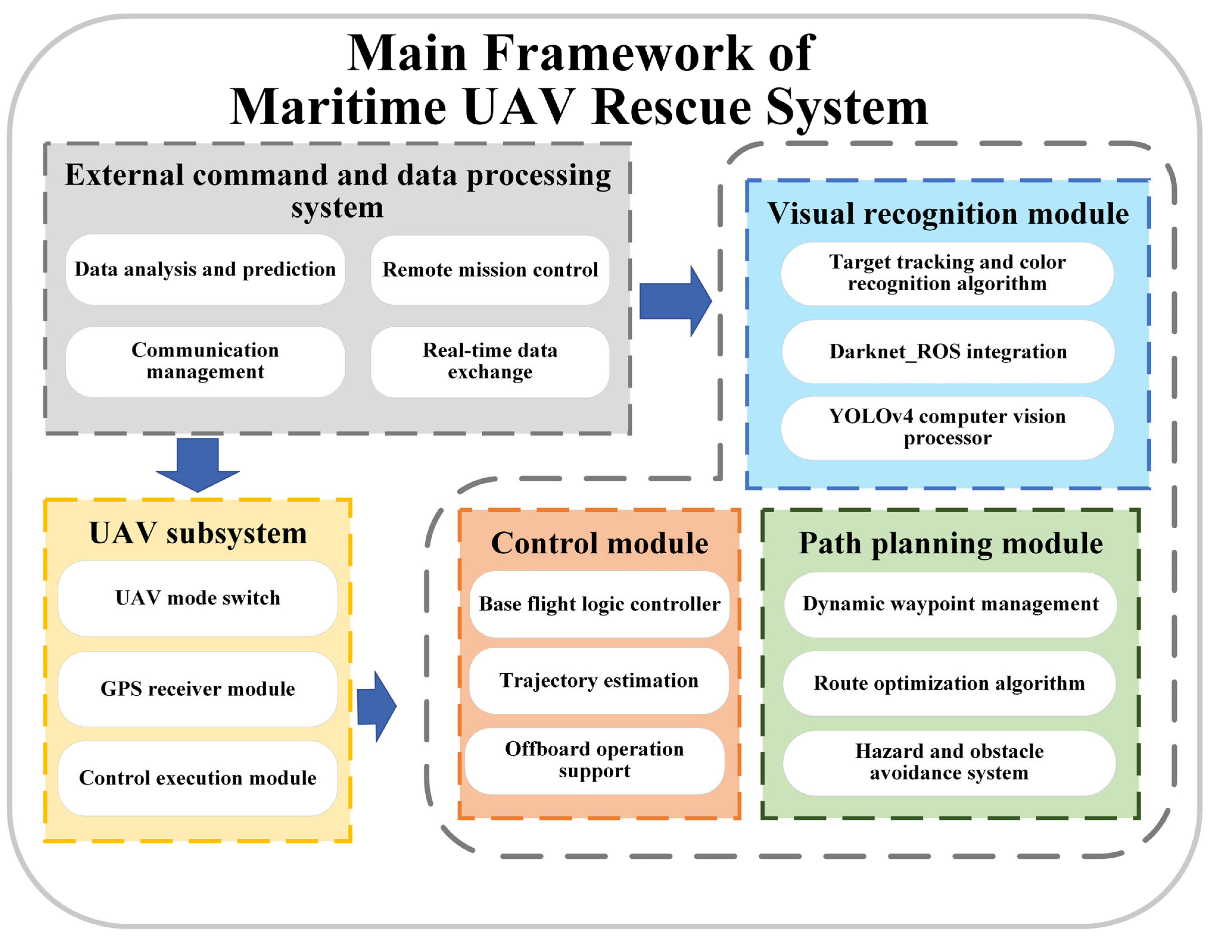
The maritime UAV rescue system proposed in this study comprises five key modules: the UAV subsystem, path-planning module, visual recognition module, control module, and an external command and data processing unit. These components are integrated to ensure efficient system coordination and successful mission execution. The overall system framework is shown in Figure 1.

Figure 1.
Main framework of maritime UAV rescue system.
A comprehensive technical pipeline has been developed for the autonomous navigation and precision landing of UAVs, encompassing all phases from mission initialization to final touchdown. The system leverages a multi-sensor fusion-based autonomous navigation algorithm, along with advanced target recognition techniques, to address challenges such as low positioning accuracy, limited target-tracking capabilities, and reduced landing precision in complex maritime environments. To further enhance performance during the final approach phase, an innovative landing scheme is introduced, as shown in Figure 2.
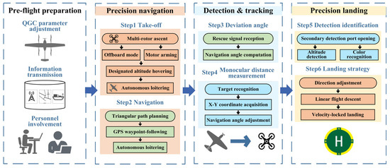
Figure 2.
Technology roadmap.
The following section outlines the sequential operational procedure of the UAV, detailing its transitions from takeoff to landing.
Specifically, after reaching the designated altitude, the UAV hovers in multi-rotor mode before switching to fixed-wing mode, maintaining its position over the takeoff point. Upon receiving the GPS guidance signal, the UAV plans an optimized flight path and hovers again at the waypoint. It then proceeds toward the true target, guided by the rescue signal, and uses its on-board vision system to distinguish between real and decoy targets. Once the true target is locked, the UAV adjusts its heading angle based on the calculated deviation and distance to the target.
The landing strategy employs a dual-target-tracking algorithm that integrates both distance detection and color-based recognition. As soon as a green landing zone is identified and the UAV descends to a predefined height threshold, the system immediately locks its propellers to perform precision landing.
3.1. UAV Autonomous Takeoff and Route Planning
Before the start of the mission, the distressed vessel transmits GPS-based coordinates for the rescue signal. Upon receiving this information, the simulated UAV takes off from the launch platform and navigates toward the designated GPS guidance point, confirming arrival upon reaching the vicinity. After takeoff, the UAV quickly transitions from multi-rotor to fixed-wing mode to minimize response time.
Given the presence of maritime hazards such as thunderstorms and typhoons, the UAV must maintain a safe distance from these zones during navigation to prevent loss of control or damage. To achieve precise maneuvering and real-time responsiveness, this study employs low-level control logic in offboard mode, allowing the UAV to be externally controlled via an autonomous command system. Relying on the modular ROS architecture and dynamic path-planning algorithms, unmanned aerial vehicles can frequently correct their flight trajectories by receiving GPS signals in real time and combining inertial navigation data, thereby reducing the impact of sea conditions on endurance. The flight control scheme is designed as follows: once the UAV attains a minimum threshold speed, it enters offboard mode and unlocks its motors. The UAV continuously monitors its position and altitude. Upon reaching the specified altitude, it hovers and switches to fixed-wing mode, stabilizing above the takeoff point. During the flight along the preplanned route, the system continuously calculates the distance between the UAV’s current position and the target waypoint. A Boolean flag is returned to indicate whether the waypoint has been reached.
The core navigation process consists of three modular functions: takeoff, reach, and check. The check function nests the reach function to verify whether the fixed-wing UAV has reached the designated GPS guidance point, at which time an arrival signal is transmitted. This modular design ensures efficient invocation and flexibility in system calls during autonomous operation.
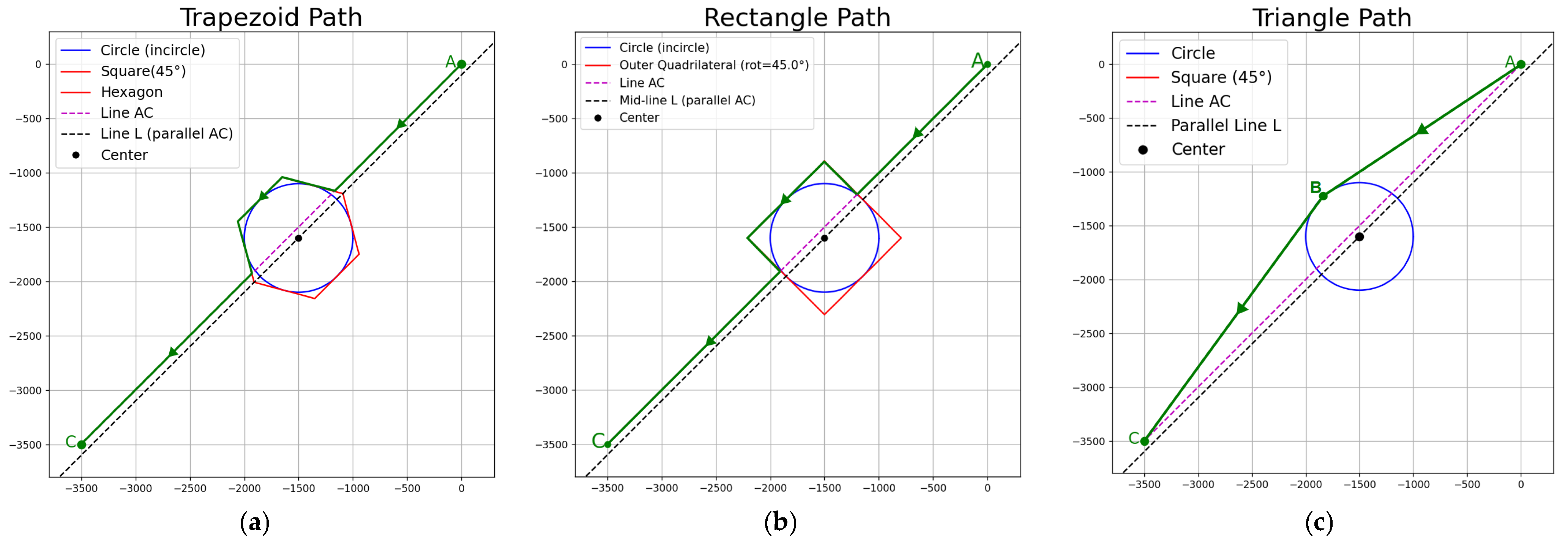
To enable rapid arrival at the target ship, the system must compute a flight route that balances safety and time efficiency. In this study, three alternative flight paths were considered—triangular, rectangular, and trapezoidal—each designed to circumvent circular disaster zones, as illustrated in Figure 3.
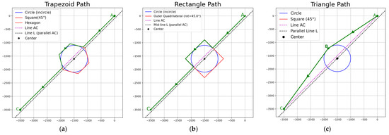
Figure 3.
Three types of path-planning schemes used for UAV rescue: (a) trapezoidal route, (b) rectangular route, and (c) triangular route.
The triangular path constructs a trajectory where the UAV departs from the starting point and flies tangentially around the perimeter of the circular hazard. Upon reaching an intermediate waypoint, the UAV adjusts its heading and proceeds directly toward the target along another tangential path. This configuration minimizes both flight distance and maneuver complexity. The rectangular path offers another viable strategy by guiding the UAV in a straight line followed by two precise 90° turns to circumnavigate the hazard zone. The UAV flies along three edges of a rectangular detour before resuming its course to the target. The trapezoidal path is geometrically similar to the rectangular configuration but utilizes segments derived from a circumscribed regular hexagon around the hazard. The UAV makes a 60° heading adjustment at each waypoint. Through the analysis of the ideal trajectories of the three paths, it is evident that the triangular path, with its simple structure and smaller turning angles, is superior to the rectangular and trapezoidal paths in terms of path complexity and turning difficulty.
3.2. Visual Detection with YOLOv4 and Distance Estimation
When the UAV successfully reaches the GPS guidance point, due to factors such as waves, wind direction, and other reasons, the position of the true target will continue to change. Ships exhibit specific movement patterns: within a certain period of time, the hull shows a tendency to move in a straight line. However, at some random moments, the ship will suddenly change its direction of movement. The deviation angle of the true target is obtained through the rescue signal issued by the ship to be rescued, and the next waypoint is calculated. At the same time, the visual recognition system is turned on. Once the true target is identified, the distance between the target and the target ship is measured.
The current direction (yaw angle) is expressed in , set for the offset angle, while the target direction is
Then, calculate the locations of waypoints. The relationship between this waypoint (,) and the UAV position (,) is as follows:
is the straight-line distance between the UAV and the waypoint.
This study conducted target recognition by compiling darknet-ROS. Before training the YOLOv4 model, a supervised data augmentation strategy was adopted to address the issue of insufficient dataset samples. The data augmentation was implemented based on OpenCV, following preset transformation rules, to expand the training dataset from the original images. The specific augmentation methods included geometric transformation operations such as image rotation, flipping, shifting, cropping, warping, and scaling. The original dataset contained 558 target images, which were manually labeled. Through the augmentation process, 5022 expanded image samples were generated for training the YOLOv4 model, enhancing the detection robustness of small targets in complex marine scenarios. The trained model demonstrated higher recognition accuracy in Gazebo simulation tests, ensuring the stability of subsequent trajectory tracking and landing tasks.
YOLO is activated, waiting for the image. Upon receiving the input image, the YOLO algorithm, integrated with the PX4 outdoor scene simulation module, commences the execution of object detection tasks. After the real target is successfully identified, the monocular camera ranging method based on the principle of similar triangles is adopted. Given the internal parameters, such as the camera’s focal length, the pixel size during shooting, and the target’s imaging size in the image, the actual distance between the UAV and the target can be calculated by establishing a mathematical model.
where is the height of the UAV, is the position change in the target pixel, and is the focal length of the camera.
Among them, the target pixel position change is directly related to the focal length of the camera.
These two distance components are combined, and the Pythagorean theorem can calculate the straight-line distance between the UAV and the target.
Following the determination of the distance between the goal and the UAV and the calculation of the angle of deviation from the true target information, the course angle is adjusted to the true target. The UAV is flown to the true target beyond the point of recognition, at which point the course angle is adjusted to align with the goal. The UAV then flies to the true target vessels, and the rotor mode is switched on during the mission.
3.3. Dual-Target Dynamic Tracking and Landing Algorithm
Dynamic tracking and precision landing on a moving vessel are critical phases in maritime UAV rescue missions. This study evaluates several landing strategies and ultimately identifies an effective method for recognizing and landing on dynamic targets at sea.
The core concept is as follows: after ascending to a designated altitude, the UAV maintains multi-rotor mode to hover and obtain a wide field of view. Within this view, the UAV detects the target vessel using on-board vision algorithms. The system calculates the distance to the target in real time via a monocular ranking algorithm. Simultaneously, the heading angle is derived from the difference between the UAV’s flight direction and the direction of the incoming rescue signal. Combining the UAV’s coordinates, heading angle, and estimated distance, the predicted trajectory of the moving vessel is established. Given that the vessel’s motion is approximately linear over short intervals, the UAV can forecast its position and preemptively navigate to the predicted point on the trajectory. Once the vessel enters the UAV’s line of sight, the UAV initiates a descent toward the vessel’s center to complete the landing task.
To ensure real-time trajectory prediction, the UAV updates these calculations every 2 s. This interval allows the system to capture a sequence of vessel positions and adjust its approach accordingly. However, due to inherent inaccuracies in monocular distance estimation, initial prediction failures may lead to cumulative trajectory errors. Furthermore, to observe the vessel’s movement, the UAV must ascend to approximately 50 m and then descend to around 5 m within 2 s—this requires a descent speed exceeding 20 m/s, which surpasses the operational capability of a multi-rotor UAV.
Therefore, although the prediction method is conceptually effective, it faces multiple challenges in practical applications, which eventually leads to its abandonment. First of all, the inherent inaccuracy of the monocular vision ranging algorithm is a primary reason. Due to the lack of depth information in monocular cameras, the distance can only be estimated based on the principle of similar triangles. This method is prone to be affected by waves, changes in illumination, and variations in target size in dynamic marine environments, resulting in the accumulation of distance estimation errors. For instance, when a drone makes an initial prediction at an altitude of 50 m, even minor angular or pixel measurement errors will be magnified in subsequent trajectory calculations, ultimately leading to the drone’s inability to accurately lock onto the target position. Secondly, the limitations of hardware performance are also a factor that cannot be ignored. The prediction method requires the unmanned aerial vehicle (UAV) to rapidly descend from a height of 50 m to 5 m within a short period (such as within 2 s), which means a descent speed of more than 20 m per second is needed, far exceeding the conventional operational capability of multi-rotor UAVs (typically the maximum descent speed is 3–5 m per second). This extreme maneuvering not only puts pressure on the structure of the unmanned aerial vehicle but also may trigger the risk of losing control or crashing.
Furthermore, the complexity of the dynamic marine environment further intensifies the difficulty of prediction. The drift motion of the target vessel is often nonlinear, especially in the case of large wind and waves. The assumption of linear motion over a short period is difficult to maintain, resulting in a significant deviation between the predicted and actual trajectories. Finally, the requirements of calculation delay and real-time performance also limit the feasibility of the prediction method. Unmanned aerial vehicles (UAVs) require updating their predictions every two seconds during flight, which poses extremely high demands for the real-time processing capabilities of on-board computing resources. Especially under low-power consumption conditions, it is challenging to simultaneously meet the demands of high precision and low latency.
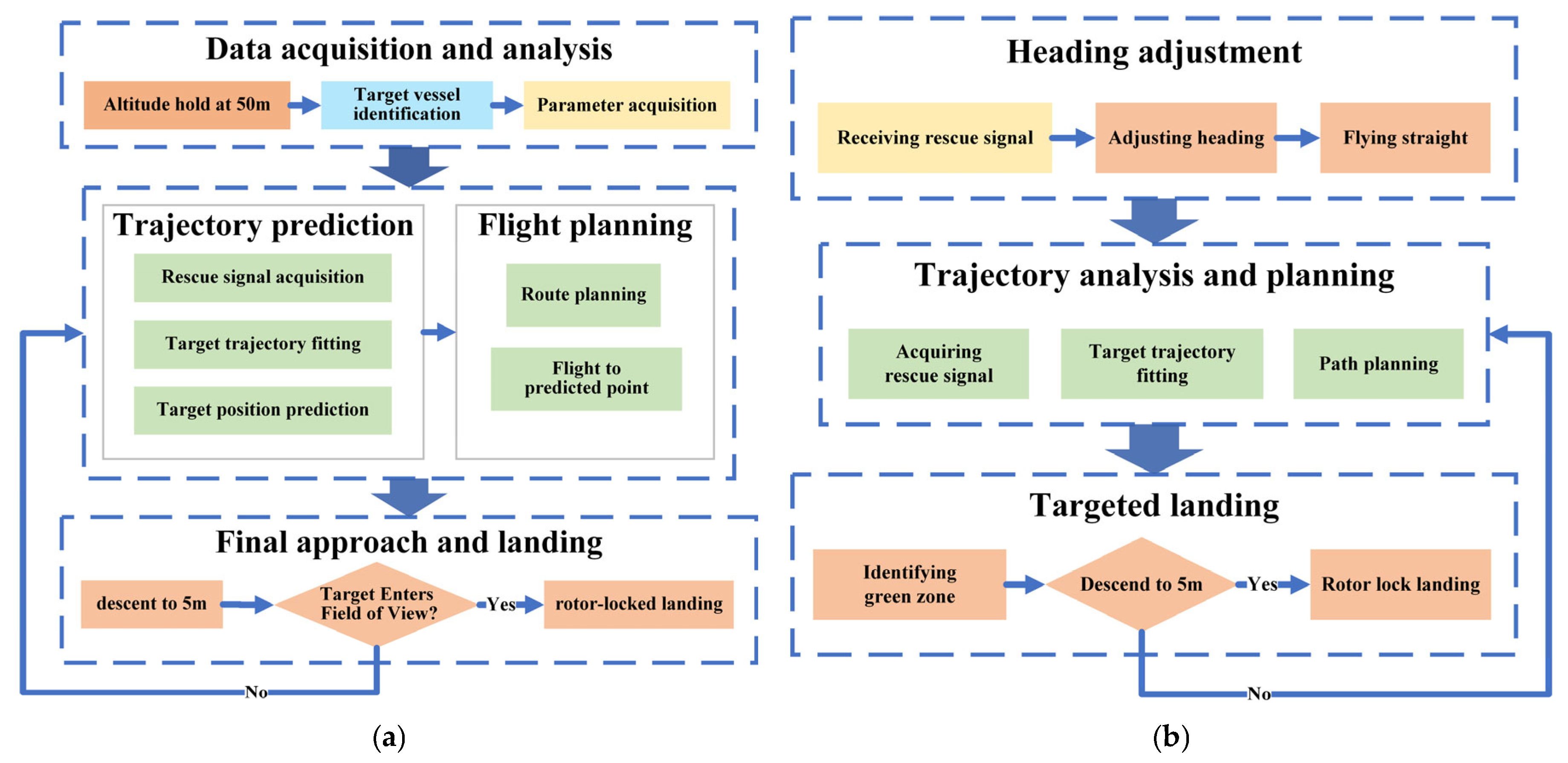
The failure of the prediction method directly prompted the research to shift to a more reliable dual-object recognition scheme. Multiple improvements were integrated into the final design to address the original defects, as shown in Figure 4.
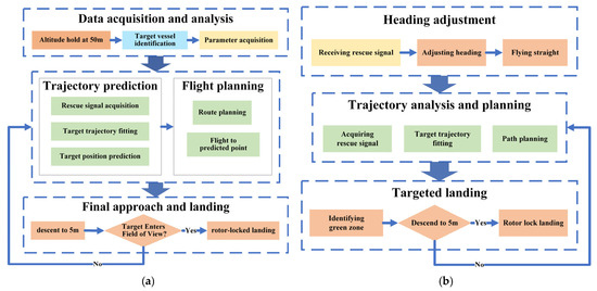
Figure 4.
Landing strategies: (a) schematic diagram of the prediction algorithm landing scheme and (b) schematic diagram of the dual target recognition landing scheme.
Firstly, the dual-object recognition method eliminates reliance on motion trajectories and instead utilizes static features (such as the green landing area) as the primary reference, thereby avoiding the issue of error accumulation in dynamic prediction. This design choice significantly enhances the system’s robustness. Especially when the target is briefly occluded, or the image is blurred, the unmanned aerial vehicle can still lock onto the landing site through color features. Secondly, the final method optimizes the height control strategy. It no longer relies on extreme descent speeds. Still, it approaches the target in stages (such as hovering first and then descending slowly), thereby better matching the performance limitations of multi-rotor unmanned aerial vehicles.
Furthermore, the dual-target recognition framework implements a hierarchical verification mechanism by combining the long-range target detection and short-range color recognition capabilities of YOLOv4. The first-layer detection window ensures the accuracy of the initial target positioning, and the second-layer window further confirms the target through a color threshold before landing, effectively reducing the risk of misjudgment. This hierarchical design not only compensates for the deficiency of single-eye distance measurement but also enhances the system’s fault tolerance ability through multimodal data fusion. These improvements collectively enabled the final method to achieve a landing success rate of 96% in the experiment.
4. Results
4.1. Experimental Environment
This study was conducted using the Gazebo simulation environment, which offers a robust platform for evaluating maritime UAV rescue systems. With its high-fidelity physics engine, extensive model library, and flexible plug-in architecture, Gazebo can realistically replicate various elements of maritime environments—including wave dynamics, airflow turbulence, and visibility variation [32]. These features ensure that the UAV’s simulated flight behavior closely mirrors real-world conditions, lending credibility to the experimental results.
The UAV’s takeoff platform was designated as the starting point, located at coordinates (2300, 2300). The GPS guidance point, representing the approximate location of the distressed target or the rescue zone, was set at coordinates (–1200, –1200). To simulate environmental hazards, we defined a circular thunderstorm area with a radius of 500. Meanwhile, to simulate the randomness of the marine environment, the center of the thunderstorm circle is randomly generated within a square area with (600, 600) as its center and a side length of 200 units. The simulated turbulence and low visibility in the thunderstorm area pose significant challenges to the flight stability, sensor accuracy, and communication reliability of UAVs. This setting effectively simulates extreme maritime conditions and can serve as a reliable benchmark for testing disaster avoidance capabilities.
At the start of the simulation, the UAV is stationed at the takeoff platform. Upon receiving the start command, it initiates vertical ascent in multi-rotor mode, reaches a predefined altitude, transmits its coordinates, and subsequently switches to fixed-wing mode under autonomous program control.
Once the GPS guidance point is received, the UAV utilizes its on-board intelligent path-planning algorithm, considering terrain, simulated weather conditions, and other environmental data, to generate an optimal flight trajectory. This trajectory is based on the triangular path-planning strategy proposed in this study. As the UAV follows this trajectory, it successfully avoids simulated obstacles such as thunderstorms and hazardous regions. Through real-time processing of virtual sensor inputs, the UAV dynamically adjusts its attitude and heading, ensuring a safe and efficient arrival at the guidance point.
Upon reaching the GPS guidance location, the UAV transitions to the target recognition phase. The on-board YOLOv4 model is activated, and the simulated camera continuously captures the surrounding environment. The UAV then rapidly identifies and locks onto the real distressed ship.
As the distance between the UAV and the target vessel decreases, the UAV switches back to multi-rotor mode at the appropriate moment to prepare for landing. Once it enters the designated landing zone above the moving vessel, the UAV engages the custom-designed dual-target recognition and motion tracking algorithm to execute a stable and precise landing.
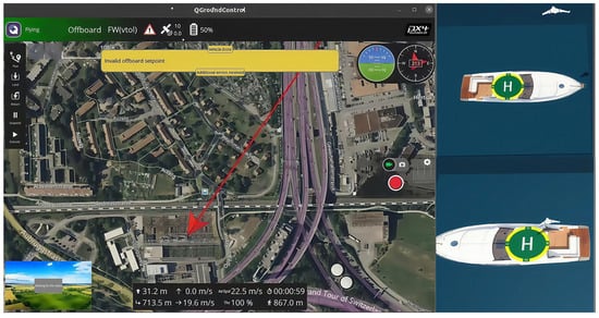
Figure 5.
Ground station interface (left). The UAV recognizes and approaches the target (top right). The UAV successfully lands (lower right).
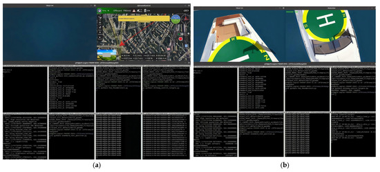
Figure 6.
Program control interface: (a) UAV flight process and (b) UAV landing.
To minimize the error of this experiment, it was repeated 50 times in total, with each repetition consisting of a group of 10 trials. To ensure the reliability of the data and prevent system overload, we waited for a certain period after the completion of each group of experiments for the next set of experiments, as shown in Table 1.

Table 1.
UAV mission performance under triangular path planning (N = 10).
It was calculated that the average time for the maritime rescue UAV to complete the mission was 8 min and 29 s, and the average route length was 6888.9 m.
The Supplementary File of the article is an MP4 format video, which can be obtained online. The Supplementary Video S1 shows the process of the experimental operation in this study. When the video image is still, it indicates the end of the task. Figure 5 and Figure 6 are both clips of the process shown in the video, and Table 1 shows the data recorded after the video process was repeated 50 times.
4.2. The Determination of the Shortest Voyage
The experiment aims to investigate the impact of various planning paths on the navigation of maritime rescue UAVs when avoiding disaster areas. In an experimental environment simulating a real sea scene, the UAV’s starting position is located at a safe distance outside the boundary area, and the GPS needs to bypass the disaster area in order to guide the point. To demonstrate the superiority of the triangular path adopted in this study, the study compared the three paths through mathematical calculations and conducted control experiments.
The three paths were analyzed using the graph, and the total length of the route was calculated mathematically based on the coordinates of each important point, with measurements taken using the drawing software’s measurement tools.
The coordinates of the experimental points are transformed according to the coordinate system in Figure 3. The center of the circular thunderstorm area is (xce, yce), where xce ∈ [−1800, −1600] and yce ∈ [−1800, −1600]. Through an analysis of the triangular path, the longer the distance from the center of the circle to the AC line, the shorter the path length. The farther the center of the circle is from the vertical bisector of AC, the longer the path length. Since the square area is symmetrical about AC, only the area where x > y needs to be considered. When the coordinates of the center of the circle are (−1600, 1600), the distance between the center of the circle and AC is 0, and it is farthest from the perpendicular bisector of AC. The path of the triangle is the longest, with a length of 5054.794 m. When the path is the shortest, the center of the circle is on the edge of the square area. The point (−1600, −1800) is the farthest from AC, and the distance between the point (−1700, −1800) and the perpendicular bisector of AC is 0. Therefore, on the line segment formed by connecting these two points, there exists a special point that makes the path of the triangle the shortest. Let the center of the circle be O(a, −1800), and a ∈ [−1700,−1600]; The functions of paths AB and CB are, respectively, y = k1x and y = k2x + 3500(k2−1), where k1 < 1 and k2 > 1. The coordinates of intersection point B are (,).
According to the distance formula,
Since kd = 500, substituting the coordinates of point O and the path function yields k1 and k2. Based on the coordinates of A, B, and C, the path length function is calculated as F(a). When a ∈ [−1700, −1600], its derivative f(a) < 0. Therefore, when the center of the circle is (−1600, −1800), the path of the triangle is the shortest, and the shortest path is 5003.031 m. To sum up, the length range of the triangular path is [5003.031, 5054.194] m. An analysis of the rectangular path and the trapezoidal path reveals that when the center of the circle moves along the AC direction, the path configuration remains unchanged, and the path length remains constant. The path is the longest when the center of the circle falls exactly on AC. The path is the longest when the center of the circle is located at two points: (−1800, −1600) and (−1600, −1800). After measurement, the range of the rectangular path is [5666.905, 5949.747] m; the trapezoidal path range is [5363.798, 5527.096] m.
This study sets up comparison experiments of three paths to ensure the accurate acquisition of flight trajectory and flight distance data. Each path experiment was repeated 20 times to eliminate accidental errors, and the average value was taken as the final result. The data is shown in Table 2 and Figure 7.
Table 2.
Comparison of average path lengths across three different planning methods.
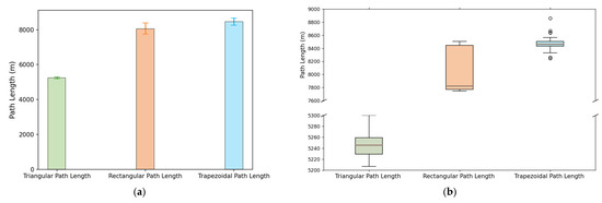
Figure 7.
Three methods of path length: (a) comparison of mean and standard deviation and (b) distribution.
According to the experimental data, the triangular path yields the shortest route for the UAV. In contrast, the rectangular path is 53.8% longer, and the trapezoidal path is 61.4% longer. When using rectangular or trapezoidal paths, fixed-wing UAVs must circle at each waypoint before proceeding, increasing both flight time and path-planning complexity.
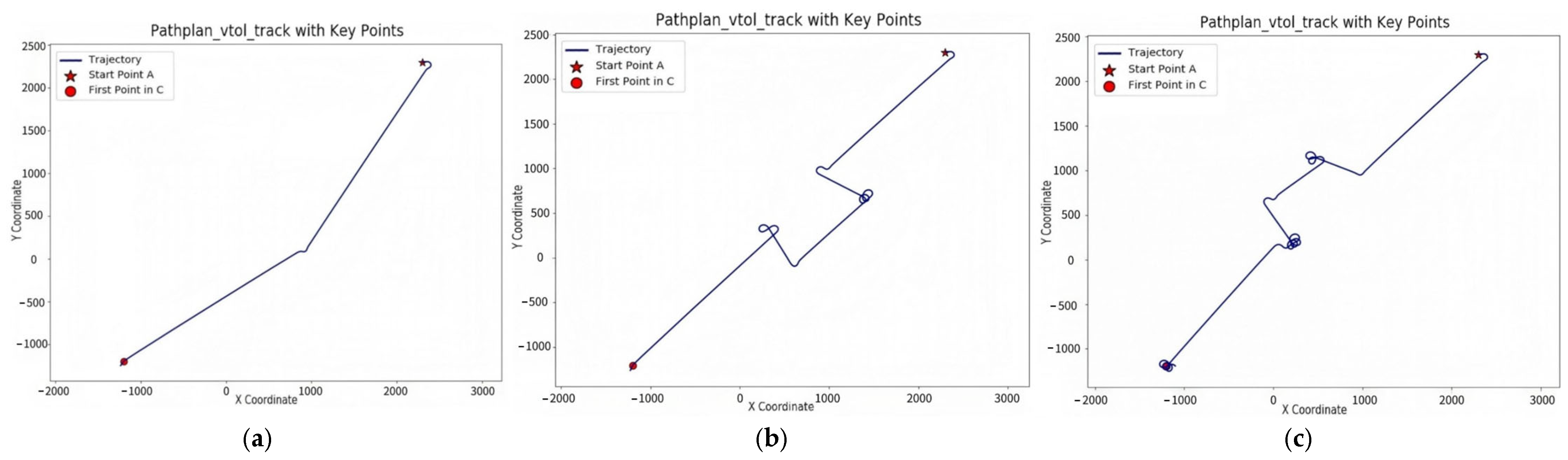
An analysis of Figure 8 reveals that, since the unmanned aerial vehicle is in offboard mode when it reaches the waypoint, it must send the arrival signal and then begin circling to await the ground station’s transmission of the next waypoint’s position. In the triangular path, when the unmanned aerial vehicle (UAV) reaches the first waypoint, it begins to circle it. The next waypoint has been determined, namely the GPS guidance point. The ground station immediately sends the coordinates, and the UAV begins to sail. In trapezoidal and rectangular paths, when the unmanned aerial vehicle (UAV) reaches the intermediate waypoint, the position of the next waypoint must be calculated using a specific algorithm and then transmitted by the ground station. The continuous hovering of the UAV at this stage leads to an increase in flight time and distance. Furthermore, the coefficient of variation (CV) of the triangular path is only 4.7 × 10⁻³, indicating that the path length is not significantly affected by internal system factors and operates stably. The results demonstrate that the triangular path is both effective and scientifically sound for UAV rescue missions.
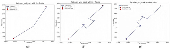
Figure 8.
Three types of path trajectory diagrams: (a) triangular route, (b) rectangular route, and (c) trapezoidal route.
4.3. Advantages of Motion Tracking Algorithm for Dual Target Recognition
The dual-target motion tracking algorithm developed in this study enhances the accuracy and stability of UAV landings. During descent, the UAV continuously adjusts its heading based on real-time rescue signals from the true target. Once aligned, it proceeds with a stable vertical descent. This delay in descent initiation improves flight stability and landing precision.
The true target is marked with a distinctive green area for color recognition. When the UAV detects this green region and reaches the appropriate altitude, it immediately locks its propellers and initiates landing, achieving an accurate touchdown. The UAV autonomously determines its distance from the target. When the green area occupies at least 95% of the detection window and the target ship’s width ranges between 2 and 5 m, the calculated UAV-to-target distance ranges from approximately 1.93 to 3.42 m. This satisfies the optimal range for reliable color-based recognition.
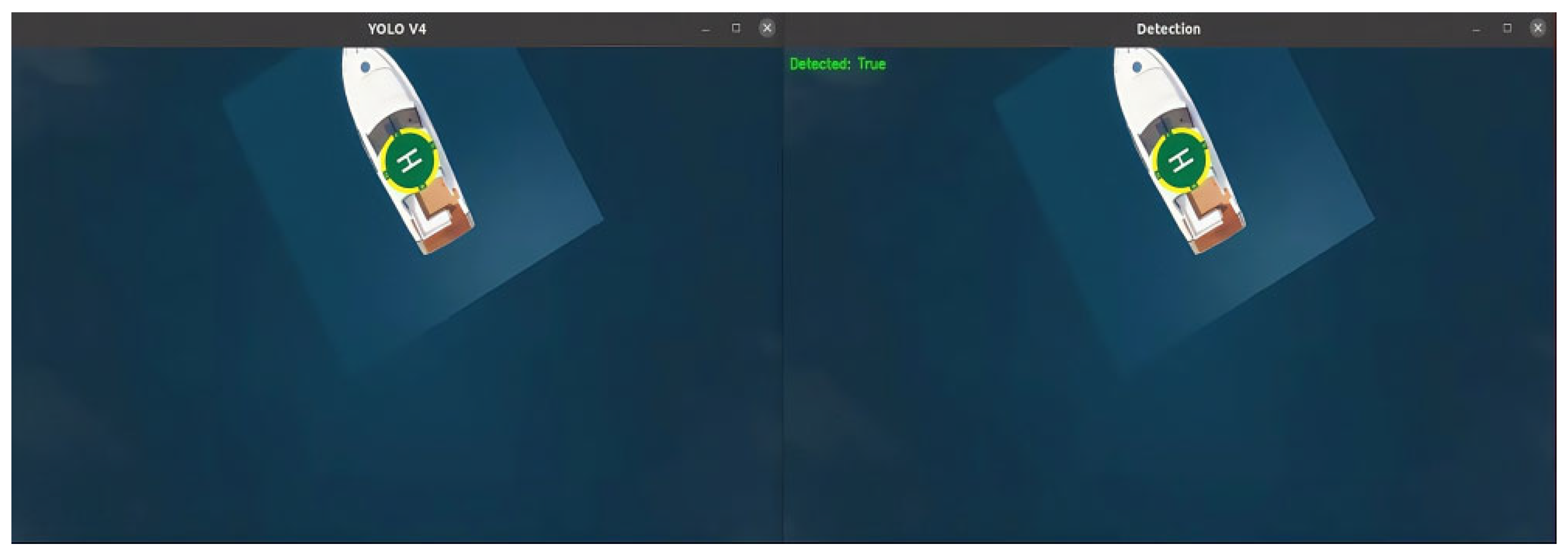
Figure 9 illustrates the dual recognition framework:
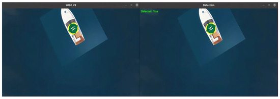
Figure 9.
YOLO v4 window (left) and landing detection window (right).
- The first detection window, using the YOLOv4 model, identifies the real target from a distance.
- The second detection window activates during landing. If image conditions meet preset thresholds (e.g., green area coverage), the UAV locks its OARS and lands.
In addition to color recognition, a monocular-based distance estimation algorithm was implemented. This method outputs image parameters to estimate the UAV’s distance to the target and determine whether it is within the acceptable landing range.
A set of comparative experiments was conducted to evaluate the landing efficiency of both methods. The results are presented in Table 3.
Table 3.
Experimental results of distance-based vs. dual-target landing methods.
According to an analysis of the experimental data, the important factors that cause the difference between the results of any two experiments are
- The center of the disaster area is randomly generated, resulting in different flight distances.
- The target detection efficiency is low, which can lead to a failure to land after approaching, and it is necessary to approach again before detection is possible.
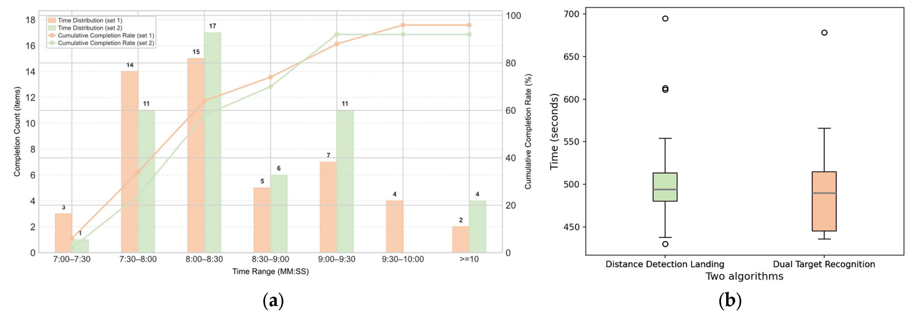
Given that the length of the triangular path ranges from 5003.031 m to 5054.194 m, the variation in length is approximately 50 m. Additionally, the UAV operates in fixed-wing mode, so factor 1 can be disregarded. Therefore, the primary reason for the different completion times of the maritime rescue mission is the varying target detection efficiency of the UAV during landing. In this study, a landing time exceeding 10 min is defined as a failure. The comparison of the distance detection algorithm (set 1) and the dual-target recognition and motion tracking algorithm (set 2) is shown in Figure 10.
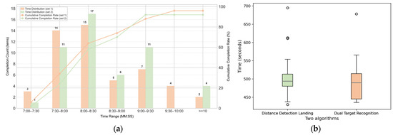
Figure 10.
The effects of two tracking landing strategies: (a) comparison of time distribution and completion rate and (b) distribution of the required time.
As shown in the figure, the average landing time of the dual-target recognition motion tracking algorithm is 8 min and 29 s, with a success rate of 96%. The average landing time of the distance detection algorithm is 8 min and 37 s, with a success rate of 92%. The new landing algorithm designed in this study has reduced the time required for the task by 1.41% and increased the success rate by 4%, thereby improving landing efficiency.
5. Discussion
In this study, we developed an intelligent UAV-based rescue system leveraging multimodal heterogeneous data fusion to address the challenges of search and rescue (SAR) operations in complex maritime environments. By integrating GPS-based dynamic path planning, YOLOv4-enhanced visual recognition, and a dual-modal tracking algorithm, the system tackles critical limitations in traditional rescue strategies—namely, redundant path planning, inconsistent target acquisition, and low-accuracy dynamic landings. Experimental results in a high-fidelity Gazebo simulation demonstrate a landing success rate of 96% and an average flight distance of 6888.9 m, representing a 4% performance improvement over conventional approaches. This validates the proposed architecture as a technically feasible and efficient solution for the deployment of maritime UAVs.
The simulation experiments in this study were established based on real marine environments, and the results demonstrate that the drone exhibits good adaptability to the actual maritime environment. In the simulation experiments, the range of GPS waypoints, in conjunction with visual technology, mitigates the impact of GPS drift on route planning and navigation, thereby enhancing the navigation reliability of the drone. When encountering low-visibility weather conditions such as dense fog or heavy rain, the YOLOv4 model, after being trained on images with adjusted color schemes, can adapt to complex lighting conditions and successfully complete rescue missions. Additionally, the experiments simulated random changes in the motion direction of ships under the influence of waves. With the combination of a dual-target-tracking algorithm and a motion prediction mechanism, the drone maintains a high success rate for landing in dynamic scenarios.
From a practical standpoint, the system demonstrates three notable deployment advantages:
- Adaptability to congested maritime environments: The triangular path-planning algorithm ensures safe UAV navigation in port channels by enabling real-time disaster avoidance and mitigation.
- Robustness in occluded target conditions: The dual-target-tracking mechanism supports reliable identification and locking in complex nearshore aquaculture environments where visual occlusions are common.
- Lightweight and low-latency visual inference: The monocular ranging module achieves a positioning error of less than 0.35 m within a 30 m radius, offering a viable solution for emergency supply delivery on offshore drilling platforms.
Despite these advances, several limitations remain:
- Simulation-to-reality gap: The simulated environment cannot fully replicate the stochastic nature of real-world sea states.
- Limited scalability for multi-UAV coordination: The current system architecture lacks support for multi-agent cooperative rescue tasks.
- Real-time processing constraints: On-board computation under low-power conditions introduces latency bottlenecks for inference and control.
- The strong dependence on the setting of the green area for damaged ships limits the application scenarios: The landing conditions of unmanned aerial vehicles are bound to the size judgment of the green area of the hull in the visual camera. However, in actual disaster scenarios, damage to ships may cause the green area to be covered, damaged, or deformed, and even old or non-standard ships without this identification cannot meet the landing conditions.
- The contradiction between the static environment assumption and the reality of dynamic maritime scenarios: The research assumes that the disaster area remains stationary during the flight of unmanned aerial vehicles (UAVs) without fully considering the dynamic change characteristics of the maritime environment, such as moving storms or the drift of burning ships, resulting in poor adaptability of existing algorithms in dynamic scenarios.
To address these issues, future work will focus on the following directions:
- Construction of a multi-source heterogeneous dataset: We aim to build a cross-modal dataset that incorporates remote sensing imagery, shipborne AIS signals, and UAV-acquired multispectral images from challenging conditions, such as typhoons, night operations, and oil spills. This will support domain-adaptive few-shot learning.
- Software–hardware co-optimization: A compact on-board computing unit based on NVIDIA Jetson Orin will be developed. Through operator fusion, YOLOv4 inference latency is reduced to 23 ms. Additionally, a foldable, salt-resistant airframe structure will be designed to ensure durability in sea-state level 6 conditions.
- Edge-aware intelligent deployment: Techniques such as model quantization and knowledge distillation will be explored to compress the detection network to under 2 MB. The final system will support TensorRT acceleration and enable real-time operation on edge devices with a power consumption of under 15 W, allowing for autonomous rescue stations within 50 nautical miles offshore.
- The research and development of target feature learning and dynamic matching algo-rithms: Utilizing deep learning technology to construct a feature library of target ves-sels, by collecting visual features of hulls of different ship types and in various dam-aged states, training a neural network model with transfer learning capabilities. This enables the unmanned aerial vehicle to learn the dynamic features of the target vessel in real time during flight, combining the judgment of the size of the green area with the matching of the overall structural features of the hull, enhancing robustness in non-standard vessels and damaged scenarios.
- Develop a dynamic environmental perception system: Relying on the offboard mode characteristics of the unmanned aerial vehicle (UAV), the motion parameters of the target vessel and the surrounding environment are obtained in real-time from the ground station. Dynamic tracking algorithms, such as Kalman filtering, are used to predict the target trajectory, enabling the UAV to dynamically adjust its flight path according to real-time perceived environmental changes.
Through these advances in theory and technology, this work contributes to the paradigm shift from single-UAV intelligence to collaborative UAV networks, laying a foundational framework for future integrated “air–sea–shore” maritime emergency rescue systems.
6. Conclusions
In the face of increasingly severe ocean rescue problems, this paper proposes a maritime rescue UAV system based on GPS path-planning fusion vision, which realizes the accurate rescue of the target ship in the complex ocean environment and can determine the optimal path through the scheme obtained by our comparison in the event of marine disasters to improve the rescue efficiency. The effectiveness of the system in handling related tasks has also been verified through experiments.
Supplementary Materials
The following supporting information can be downloaded at: https://www.mdpi.com/article/10.3390/drones9070502/s1, Video S1: manuscript-supplementary.mp4.
Author Contributions
Conceptualization, S.W. and Y.Z.; data curation, C.Z., Z.J. and T.P.; methodology, C.Z.; project administration, C.S.; software, S.W.; supervision, S.W. and Y.Z.; validation, Y.Z., C.Z. and X.M.; visualization, S.W. and X.L.; writing—original draft, S.W.; writing—review and editing, Y.Z., C.Z. and Z.Z. All authors have read and agreed to the published version of the manuscript.
Funding
This paper is supported by the Open Project of the State Key Laboratory of Rotorcraft Dynamics, with the project number JZX7Y201911SY004001.
Institutional Review Board Statement
Not applicable.
Informed Consent Statement
Informed consent was obtained from all subjects involved in the study.
Data Availability Statement
The original contributions presented in this study are included in the article. Further inquiries can be directed to the corresponding author(s).
Conflicts of Interest
The authors declare no conflicts of interest.
References
- Zhang, Y.; Tao, Q.; Yin, Y. A Lightweight Man-Overboard Detection and Tracking Model Using Aerial Images for Maritime Search and Rescue. Remote Sens. 2024, 16, 165. [Google Scholar] [CrossRef]
- Rodin, C.; Dahlin, L.; Netto de Lima, L.; de Alcantara Andrade, F.A.; Barreto Haddad, D.; Johansen, T.A.; Storvold, R. Object Classification in Thermal Images Using Convolutional Neural Networks for Search and Rescue Missions with Unmanned Aerial Systems. In Proceedings of the 2018 International Joint Conference on Neural Networks (IJCNN), Rio de Janeiro, Brazil, 8–13 July 2018. [Google Scholar] [CrossRef]
- Liu, K.; Qi, Y.; Xu, G.; Li, J. Yolov5s Maritime Distress Target Detection Method Based on Swin Transformer. IET Image Process. 2024, 18, 1258–1267. [Google Scholar] [CrossRef]
- Du, L.; Fan, Y.; Gui, M.; Zhao, D. A Multi-Regional Path-Planning Method for Rescue UAVs with Priority Constraints. Drones 2023, 7, 692. [Google Scholar] [CrossRef]
- Li, Y.; Chen, W.; Fu, B.; Wu, Z.; Hao, L. A Global Coverage Path Planning Method for Multi-UAV Maritime Surveillance in Complex Obstacle Environments. Drones 2024, 8, 764. [Google Scholar] [CrossRef]
- Ferreira, D.; Basiri, M. Dynamic Target Tracking and Following with UAVs Using Multi-Target Information: Leveraging YOLOv8 and MOT Algorithms. Drones 2024, 8, 488. [Google Scholar] [CrossRef]
- Luo, Z.; Xu, H.; Xing, Y.; Zhu, C.; Jiao, Z.; Cui, C. YOLO-UFS: A Novel Detection Model for UAVs to Detect Early Forest Fires. Forests 2025, 16, 743. [Google Scholar] [CrossRef]
- Chen, D.; Chen, D.; Zhong, C.; Zhan, F. NSC-YOLOv8: A Small Target Detection Method for UAV-Acquired Images Based on Self-Adaptive Embedding. Electronics 2025, 14, 1548. [Google Scholar] [CrossRef]
- Miao, F.; Li, H.; Mei, X. Three-Dimensional Path Planning of UAVs for Offshore Rescue Based on a Modified Coati Optimization Algorithm. J. Mar. Sci. Eng. 2024, 12, 1676. [Google Scholar] [CrossRef]
- Do Trong, T.; Tran Hai, Q.; Tran Duc, N.; Thanh, H.T. A Novelty Approach to Emulate Field Data Captured by Unmanned Aerial Vehicles for Training Deep Learning Algorithms Used for Search-and-Rescue Activities at Sea. In Proceedings of the 2020 IEEE Eighth International Conference on Communications and Electronics (ICCE), Phu Quoc Island, Vietnam, 13–15 January 2021. [Google Scholar] [CrossRef]
- Suresh, M.; Swar, S.C.; Shyam, S. Autonomous Cooperative Guidance Strategies for Unmanned Aerial Vehicles During On-Board Emergency. J. Aerospace Inf. Syst. 2023, 20, 102–113. [Google Scholar] [CrossRef]
- Wang, Y.; Liu, W.; Liu, J.; Sun, C. Cooperative USV–UAV Marine Search and Rescue with Visual Navigation and Reinforcement Learning-Based Control. ISA Trans. 2023, 137, 222–235. [Google Scholar] [CrossRef]
- Chen, C.; Ma, F.; Wang, K.-L.; Liu, H.-H.; Zeng, D.-H.; Lu, P. ShipMOT: A Robust and Reliable CNN-NSA Filter Framework for Marine Radar Target Tracking. Electronics 2025, 14, 1492. [Google Scholar] [CrossRef]
- Huang, H.; Savkin, A.V.; Ni, W. Online UAV Trajectory Planning for Covert Video Surveillance of Mobile Targets. IEEE Trans. Autom. Sci. Eng. 2021, 19, 735–746. [Google Scholar] [CrossRef]
- Jayaweera, H.M.P.C.; Hanoun, S. Path Planning of Unmanned Aerial Vehicles (UAVs) in Windy Environments. UAVs 2022, 6, 101. [Google Scholar] [CrossRef]
- Wen, H.; Shi, Y.; Wang, S.; Chen, T.; Di, P.; Yang, L. Route Planning for UAVs Maritime Search and Rescue Considering the Targets Moving Situation. Ocean Eng. 2024, 310, 118623. [Google Scholar] [CrossRef]
- Meyer, J.; Sendobry, A.; Kohlbrecher, S.; Klingauf, U.; Von Stryk, O. Comprehensive Simulation of Quadrotor UAVs Using ROS and Gazebo. In Proceedings of the the Simulation, Modeling, and Programming for Autonomous Robots: Third International Conference, SIMPAR 2012, Tsukuba, Japan, 5–8 November 2012. [Google Scholar] [CrossRef]
- Smith, S.; Pan, Y.-J. Adaptive Observer-Based Super-Twisting Sliding Mode Control for Low Altitude Quadcopter Grasping. IEEE/ASME Trans. Mechatronics 2024, 30, 587–598. [Google Scholar] [CrossRef]
- Zhang, M.; Qin, H.; Lan, M.; Lin, J.; Wang, S.; Liu, K.; Lin, F.; Chen, B.M. A High Fidelity Simulator for a Quadrotor UAV Using ROS and Gazebo. In Proceedings of the IECON 2015-41st Annual Conference of the IEEE Industrial Electronics Society, Yokohama, Japan, 9–12 November 2015. [Google Scholar] [CrossRef]
- Ren, S.; He, K.; Girshick, R.; Sun, J. Faster R-CNN: Towards Real-Time Object Detection with Region Proposal Networks. Adv. Neural Inf. Process. Syst. 2015, 28, 1137–1149. [Google Scholar] [CrossRef]
- Redmon, J.; Divvala, S.; Girshick, R.; Farhadi, A. You Only Look Once: Unified, Real-Time Object Detection. In Proceedings of the IEEE Conference on Computer Vision and Pattern Recognition, Las Vegas, NV, USA, 27–30 June 2016. [Google Scholar] [CrossRef]
- Xu, J.; Fan, X.; Jian, H.; Xu, C.; Bei, W.; Ge, Q.; Zhao, T. YOLOOW: A Spatial Scale Adaptive Real-Time Object Detection Neural Network for Open Water Search and Rescue from UAV Aerial Imagery. IEEE Trans. Geosci. Remote Sens. 2024, 62, 5623115. [Google Scholar] [CrossRef]
- Li, X.; Diao, W.; Mao, Y.; Gao, P.; Mao, X.; Li, X.; Sun, X.; Ren, L. OGMN: Occlusion-Guided Multi-Task Network for Object Detection in UAV Images. ISPRS J. Photogramm. Remote Sens. 2023, 199, 242–257. [Google Scholar] [CrossRef]
- Hermens, F. Automatic Object Detection for Behavioral Research Using YOLOv8. Behav. Res. Methods 2024, 56, 7307–7315. [Google Scholar] [CrossRef]
- Priambodo, A.S.; Arifin, F.; Nasuha, A.; Winursito, A. A Vision and GPS-Based System for Autonomous Precision Vertical Landing of UAV Quadcopter. J. Phys. Conf. Ser. 2022, 2406, 012004. [Google Scholar] [CrossRef]
- Khyasudeen, M.F.; Buniyamin, N.; Razalli Azzuhri, S.; Noor, M.B.M.; Abu Bakar, M.H.; Abd Rahman, M.F.; Kamel, N.I.; Shariffuddin, A.; Sadegh, I. The Development of a GPS-Based Autonomous Quadcopter Towards Precision Landing on Moving Platform. Int. J. Veh. Auton. Syst. 2022, 16, 108–126. [Google Scholar] [CrossRef]
- Feng, B.; Yang, X.; Wang, R.; Yan, X.; She, H.; Shan, L. Design and Implementation of Autonomous Takeoff and Landing UAV System for USV Platform. In Proceedings of the the 2022 International Conference on Cyber-Physical Social Intelligence (ICCSI), Nanjing, China, 18–21 November 2022. [Google Scholar] [CrossRef]
- Sathitwattanasan, E.; Thipyopas, C. Development of Deep Stall Landing System for Fixed-Wing Aircraft Using Image Processing. E3S Web Conf. 2024, 477, 13. [Google Scholar] [CrossRef]
- Xing, B.-Y.; Pan, F.; Feng, X.-X.; Li, W.-X.; Gao, Q. Autonomous Landing of a Micro Aerial Vehicle on a Moving Platform Using a Composite Landmark. Int. J. Aerospace Eng. 2019, 2019, 4723869. [Google Scholar] [CrossRef]
- Yu, L.; Luo, C.; Yu, X.; Jiang, X.; Yang, E.; Luo, C.; Ren, P. Deep Learning for Vision-Based Micro Aerial Vehicle Autonomous Landing. Int. J. Micro Air Veh. 2018, 10, 171–185. [Google Scholar] [CrossRef]
- Ling, K. Precision Landing of a Quadrotor UAV on a Moving Target Using Low-Cost Sensors. University of Waterloo. 2014. Available online: https://uwspace.uwaterloo.ca/items/a60fcc1b-6e6a-48f3-a60f-564b39dffd23 (accessed on 7 March 2025).
- Bingham, B.; Agüero, C.; McCarrin, M.; Klamo, J.; Malia, J.; Allen, K.; Lum, T.; Rawson, M.; Waqar, R. Toward Maritime Robotic Simulation in Gazebo. In Proceedings of the OCEANS 2019 MTS/IEEE SEATTLE, Seattle, WA, USA, 27–31 October 2019. [Google Scholar] [CrossRef]


Disclaimer/Publisher’s Note: The statements, opinions and data contained in all publications are solely those of the individual author(s) and contributor(s) and not of MDPI and/or the editor(s). MDPI and/or the editor(s) disclaim responsibility for any injury to people or property resulting from any ideas, methods, instructions or products referred to in the content. |
© 2025 by the authors. Licensee MDPI, Basel, Switzerland. This article is an open access article distributed under the terms and conditions of the Creative Commons Attribution (CC BY) license (https://creativecommons.org/licenses/by/4.0/).