Figure 1.
Progress in development of small antennas. (a) Small Antennas Gain; (b) Small Antennas bandwidth.
Figure 1.
Progress in development of small antennas. (a) Small Antennas Gain; (b) Small Antennas bandwidth.
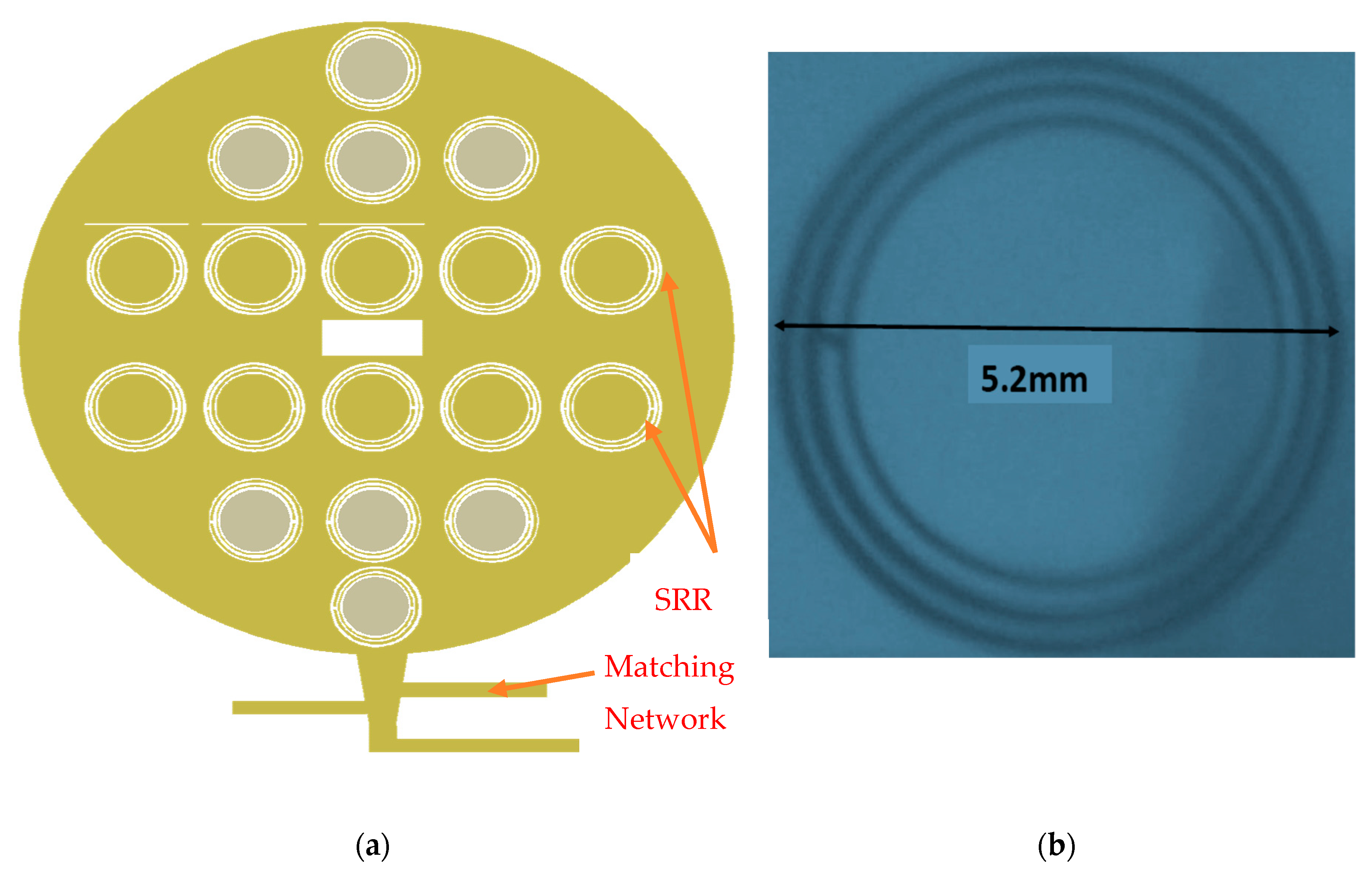
Figure 2.
(a) Circular microstrip antenna with Circular Split-Ring Resonators (CSRR); (b) Photo of a single CSRR.
Figure 2.
(a) Circular microstrip antenna with Circular Split-Ring Resonators (CSRR); (b) Photo of a single CSRR.
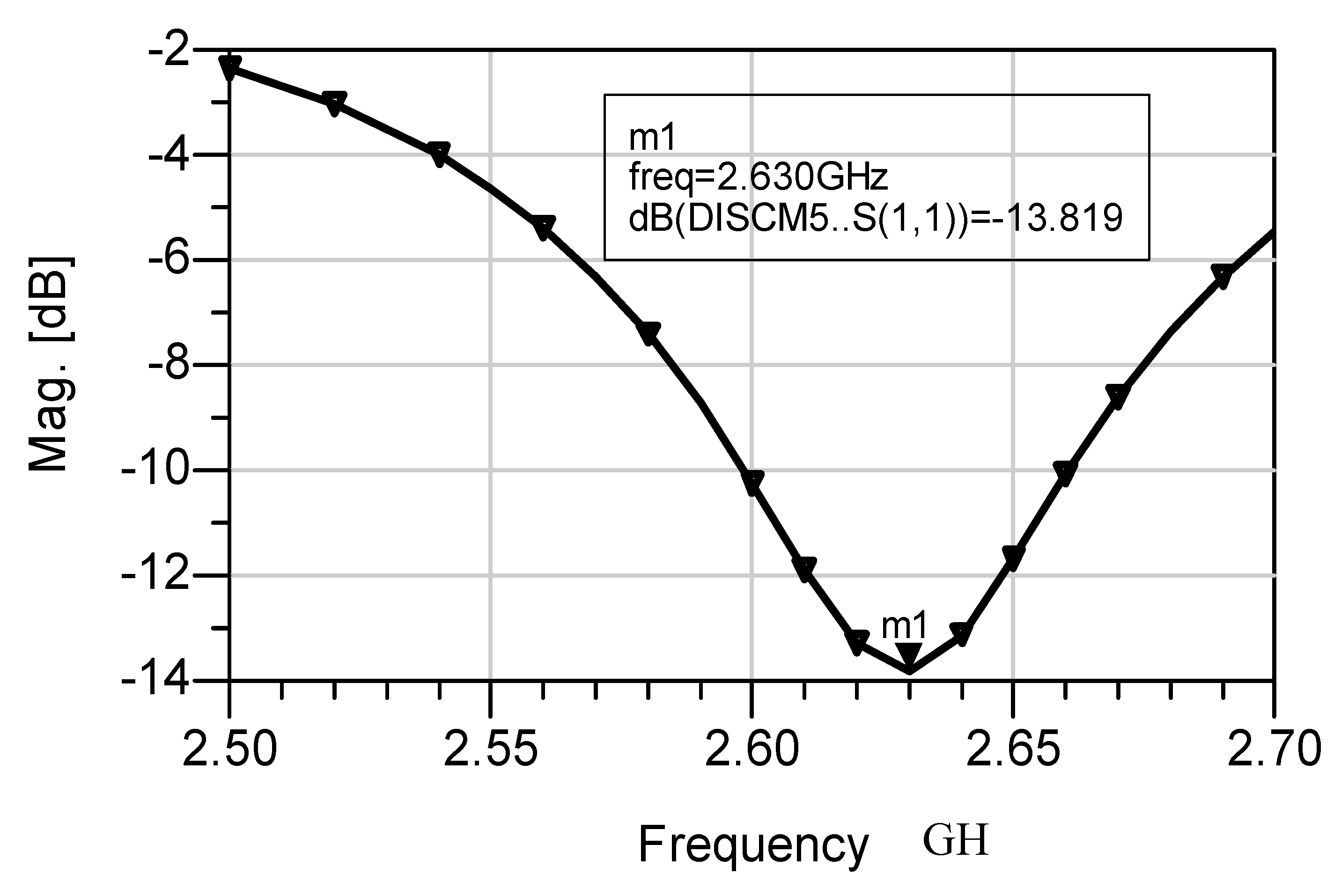
Figure 3.
S11 of the wearable circular microstrip antenna with CSRR.
Figure 3.
S11 of the wearable circular microstrip antenna with CSRR.
Figure 4.
Radiation pattern of the 2.6 GHz circular microstrip antenna with CSRR.
Figure 4.
Radiation pattern of the 2.6 GHz circular microstrip antenna with CSRR.
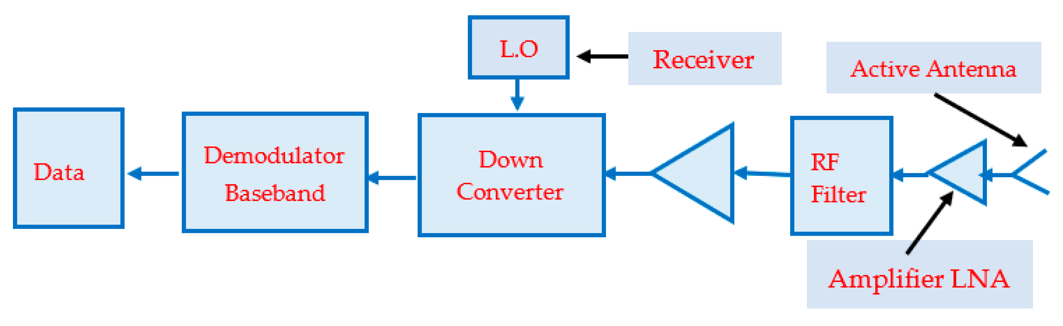
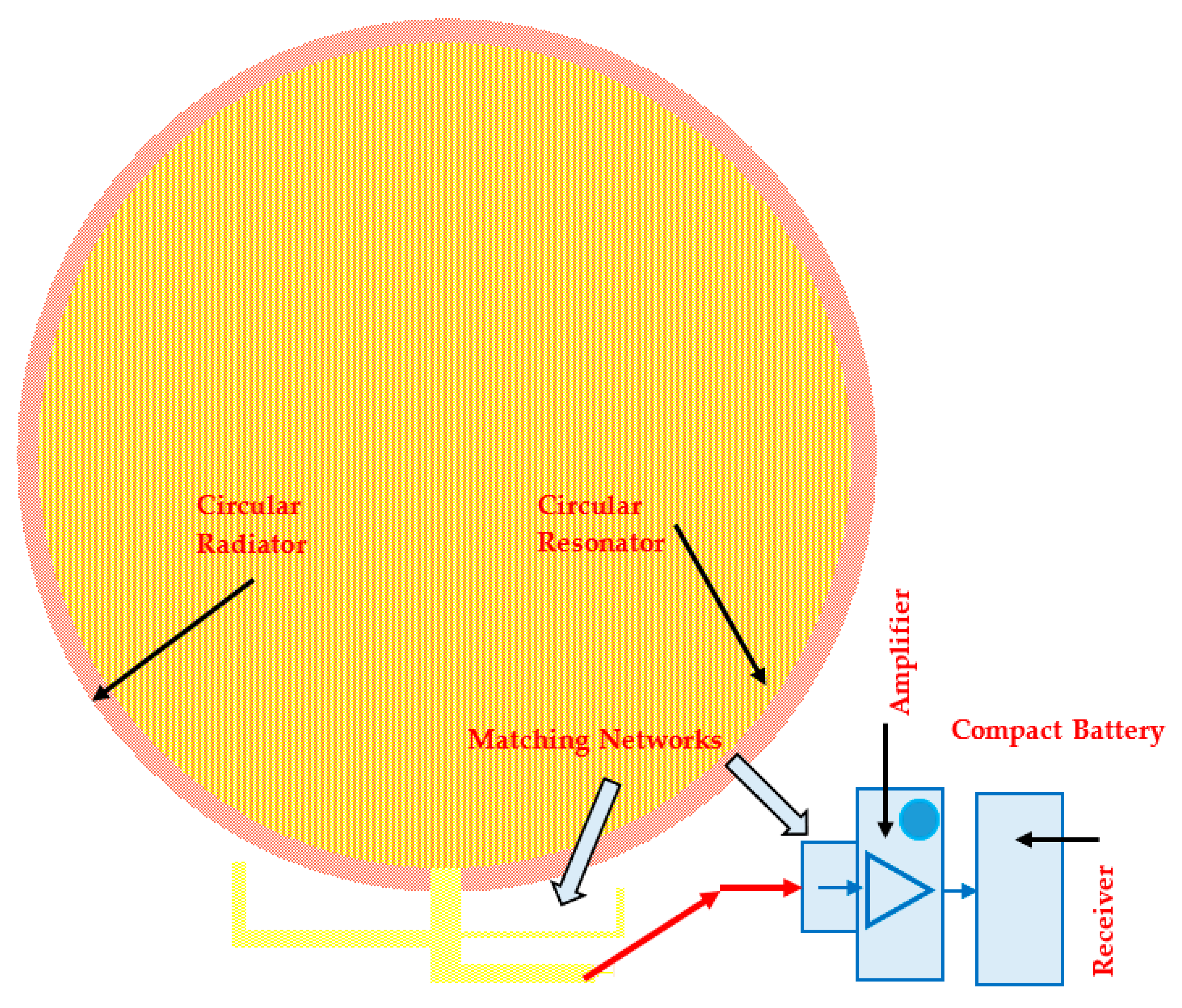
Figure 5.
Receiver block diagram with wearable active antenna.
Figure 5.
Receiver block diagram with wearable active antenna.
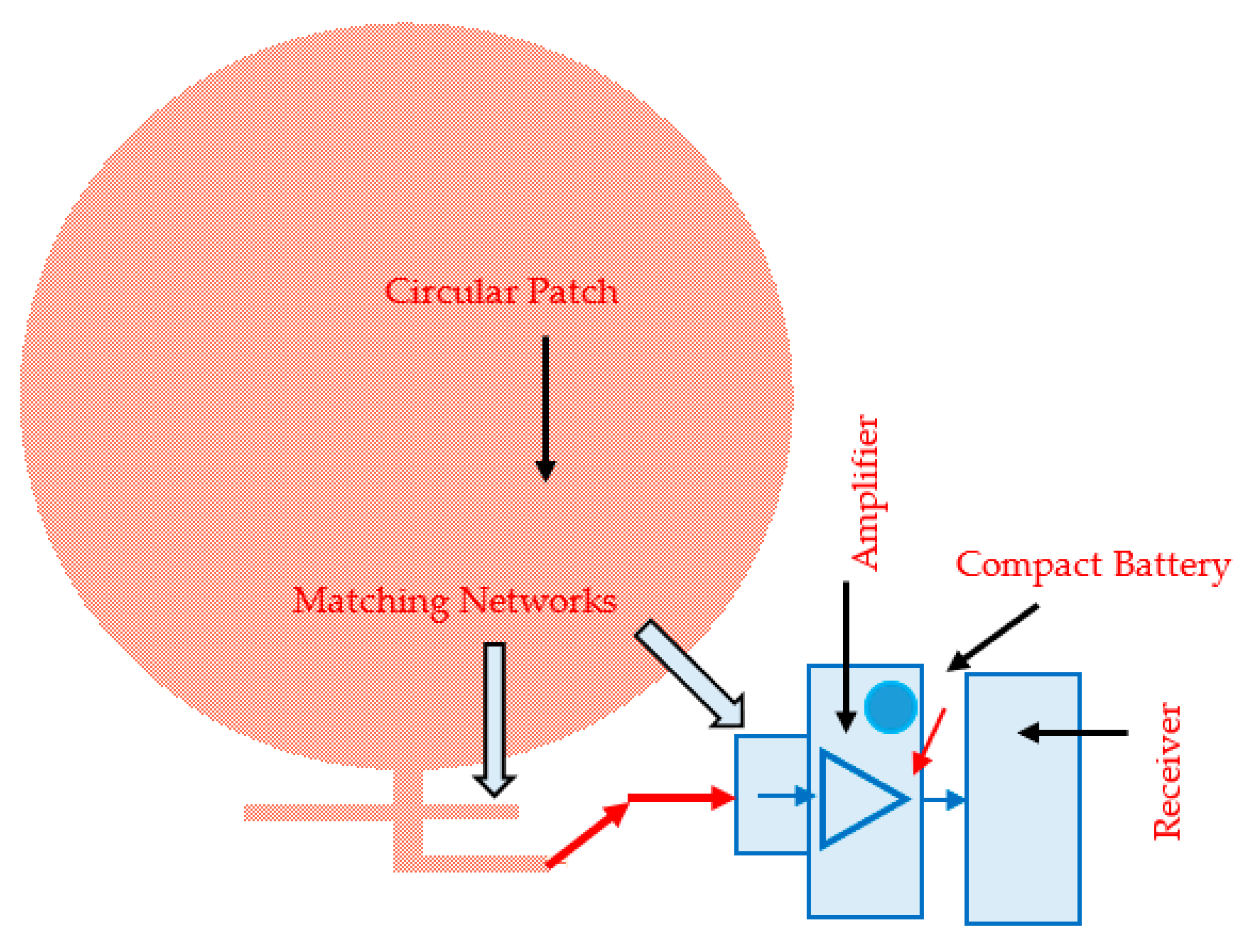
Figure 6.
Circular Wearable Active Receiving Patch antenna for Medical and 5G Applications.
Figure 6.
Circular Wearable Active Receiving Patch antenna for Medical and 5G Applications.
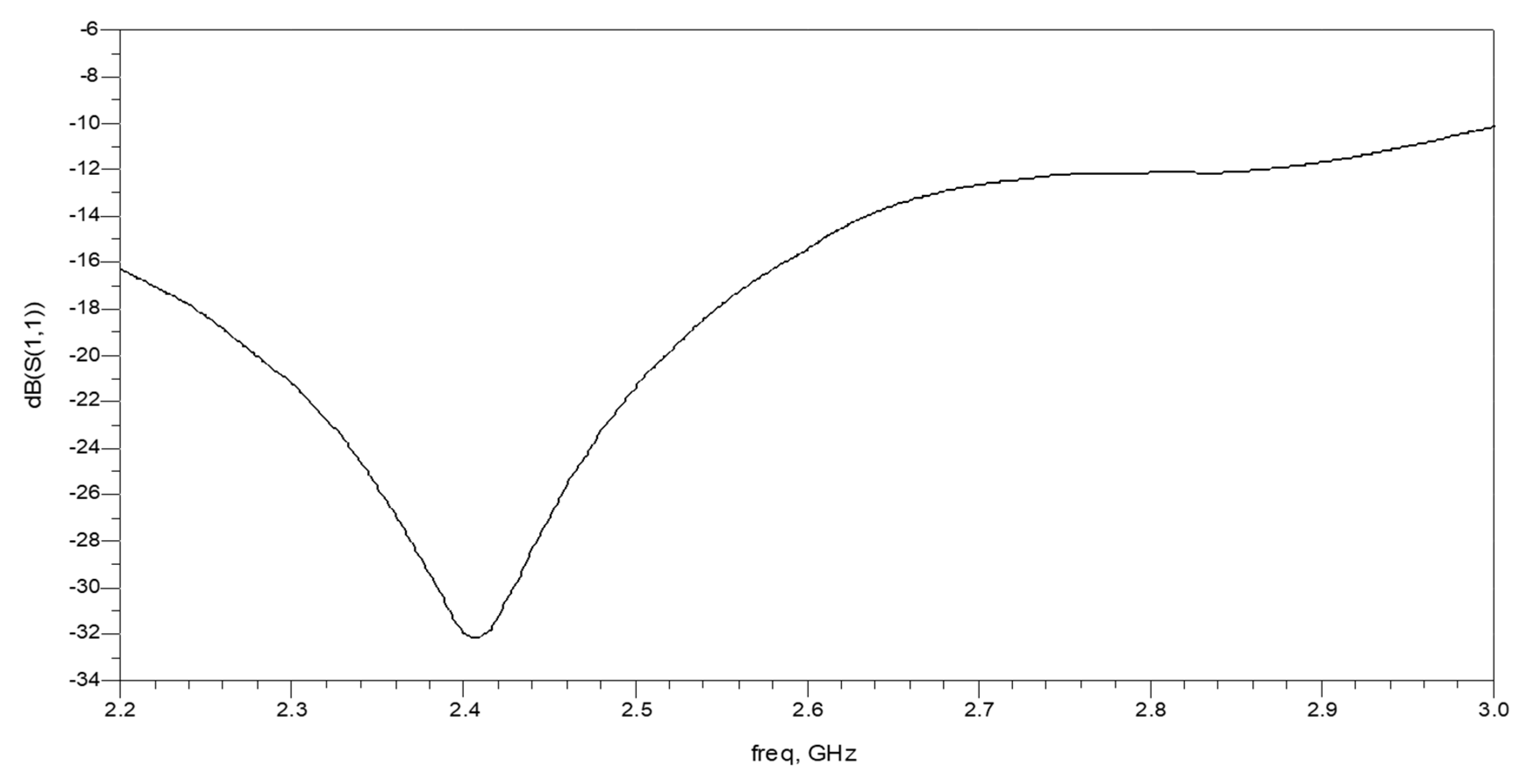
Figure 7.
S11 of the Circular patch receiving antenna.
Figure 7.
S11 of the Circular patch receiving antenna.
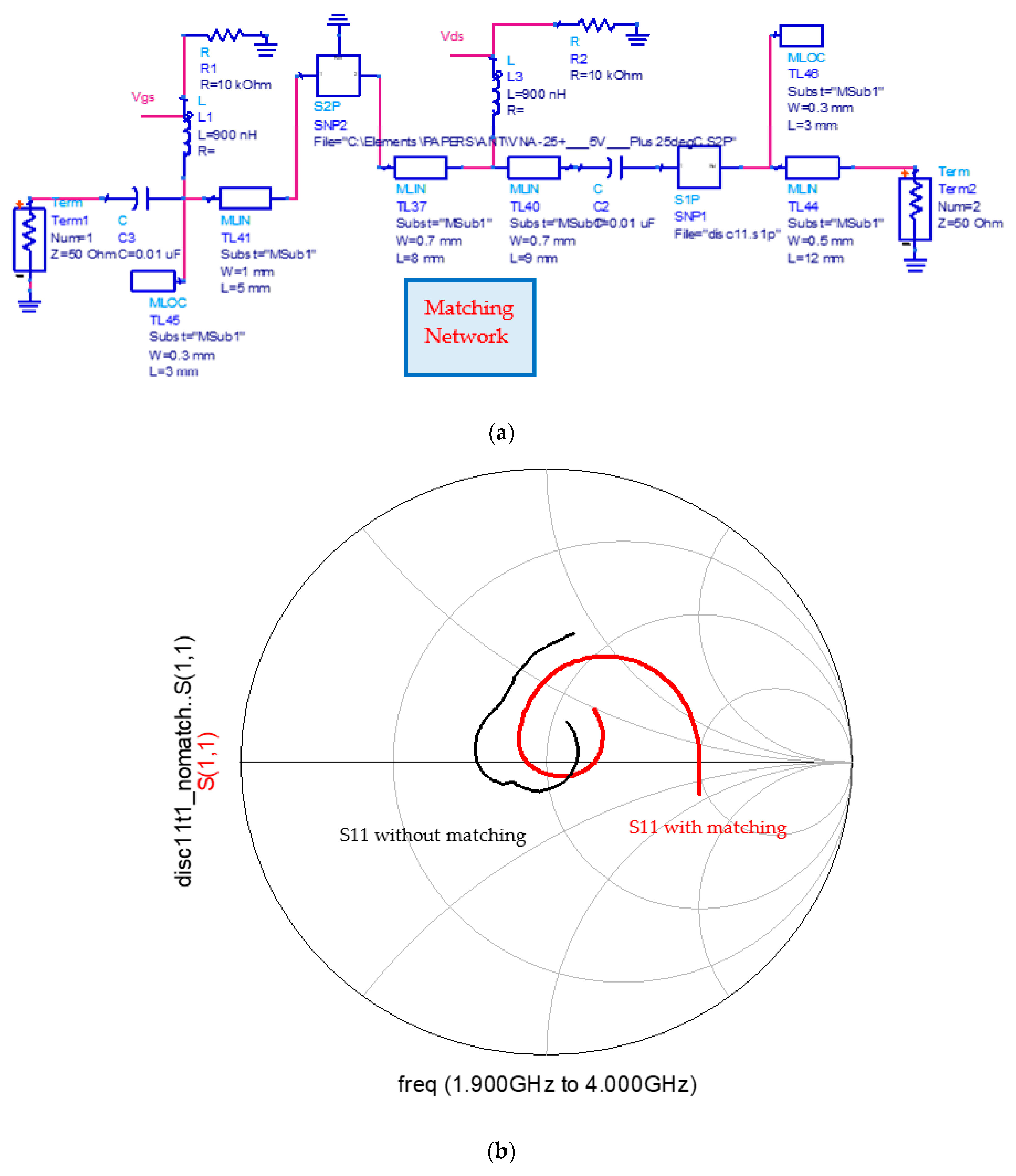
Figure 8.
Circular patch active receiving antenna. (a) Smith chart, S11; (b) Matching network.
Figure 8.
Circular patch active receiving antenna. (a) Smith chart, S11; (b) Matching network.
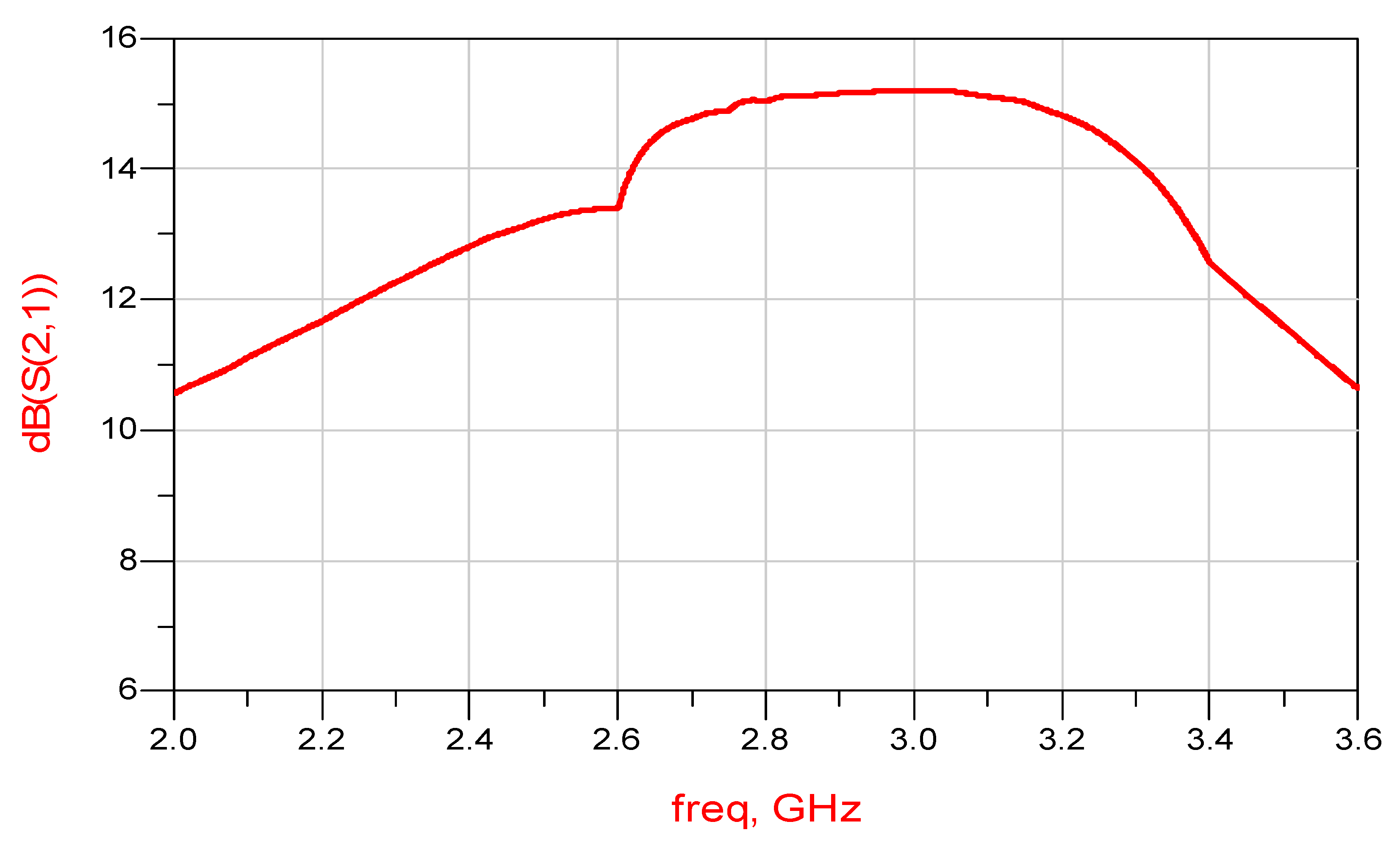
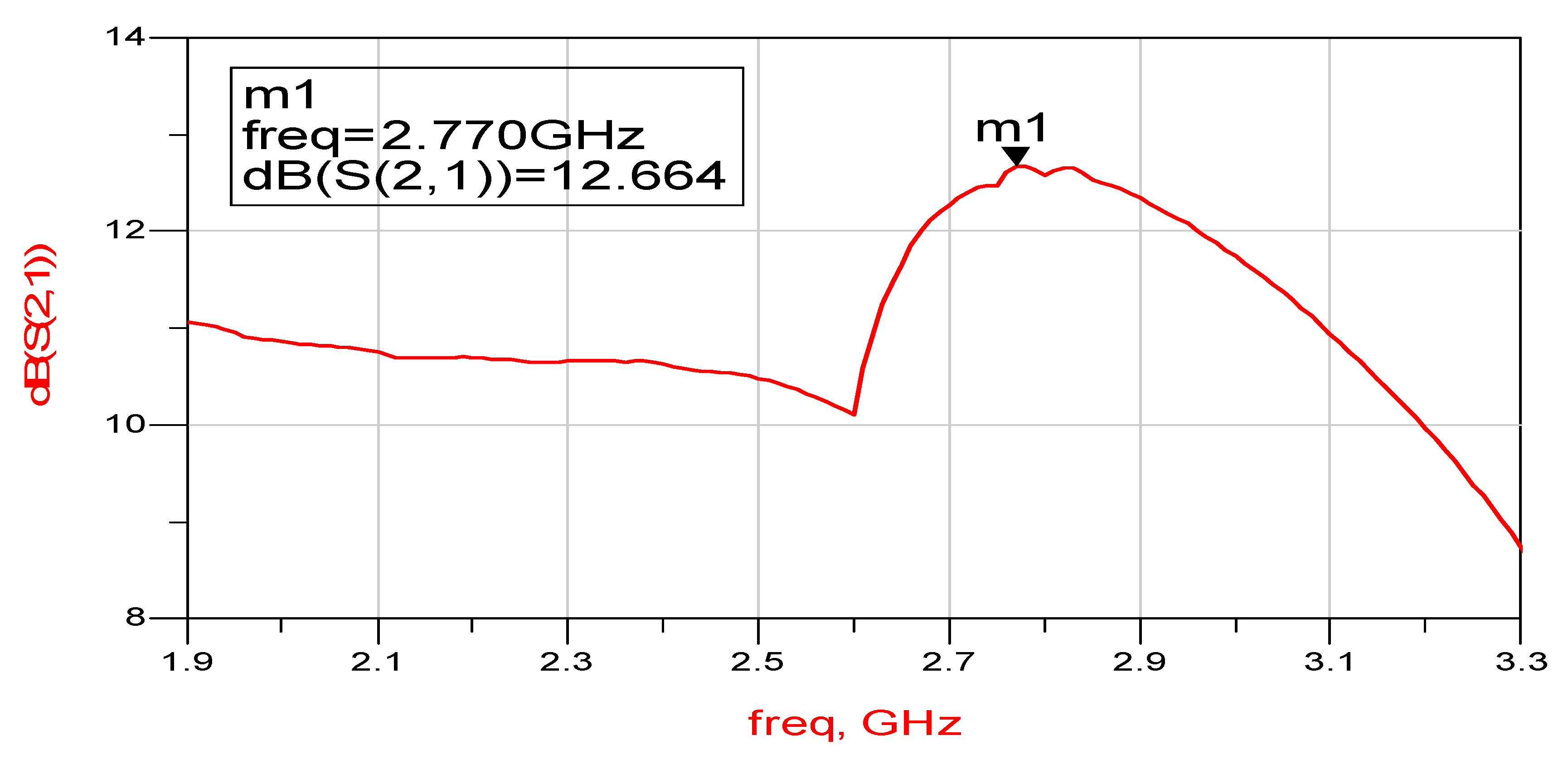
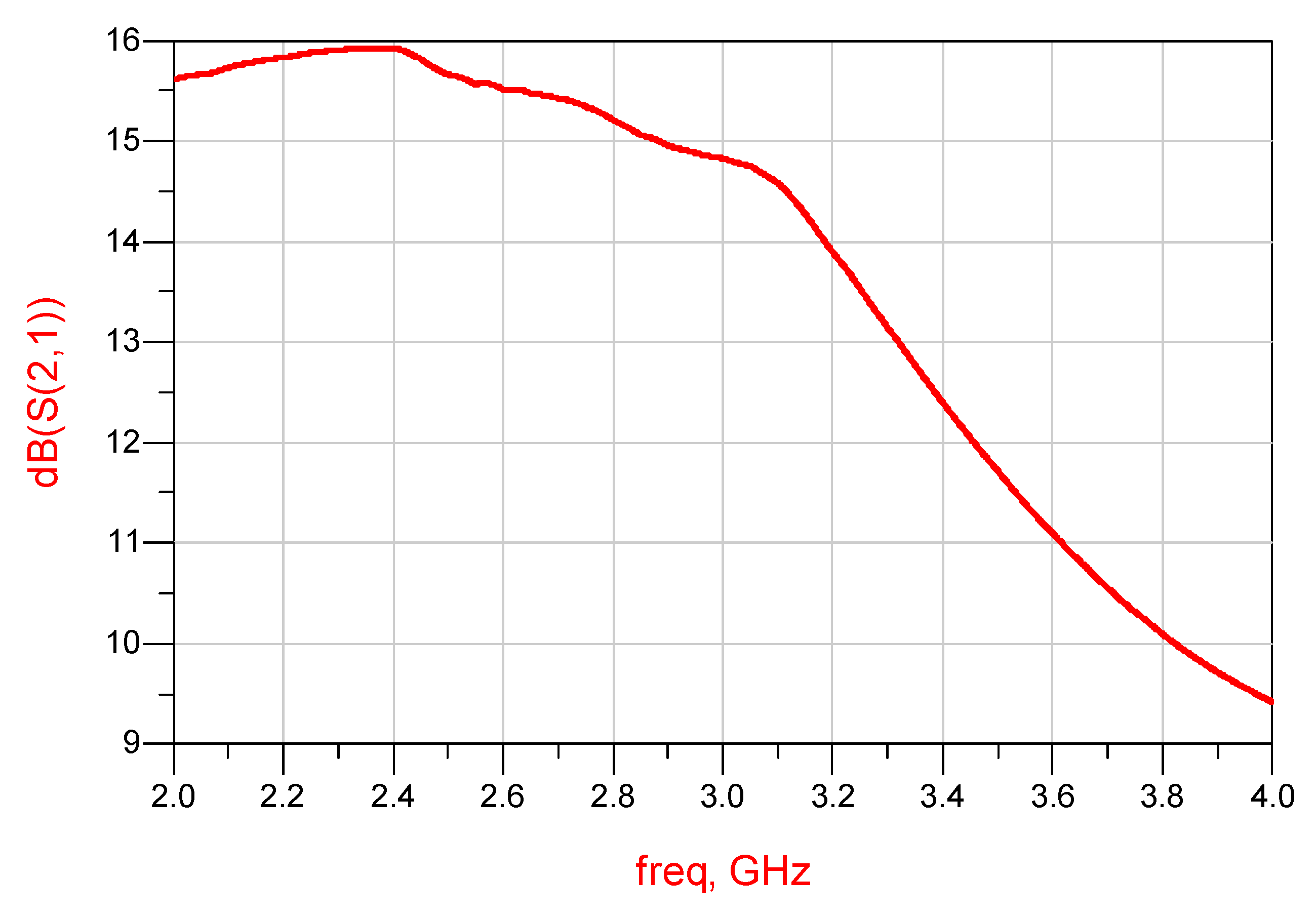
Figure 9.
S21 of an Active Circular Receiving Patch antenna.
Figure 9.
S21 of an Active Circular Receiving Patch antenna.
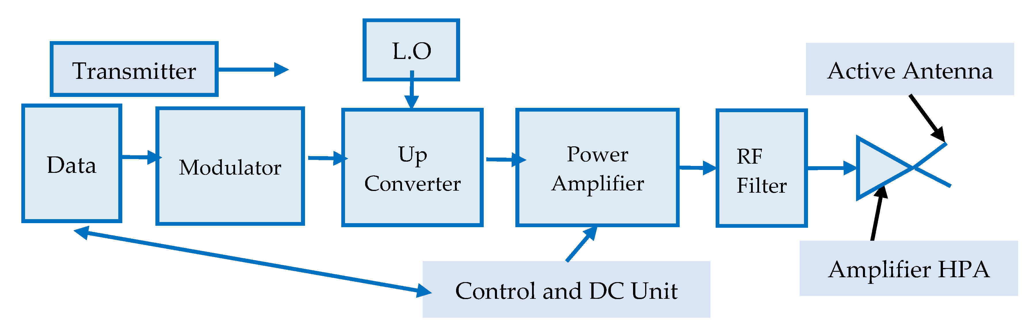
Figure 10.
Transmitter block diagram with an integral wearable active transmitting antenna.
Figure 10.
Transmitter block diagram with an integral wearable active transmitting antenna.
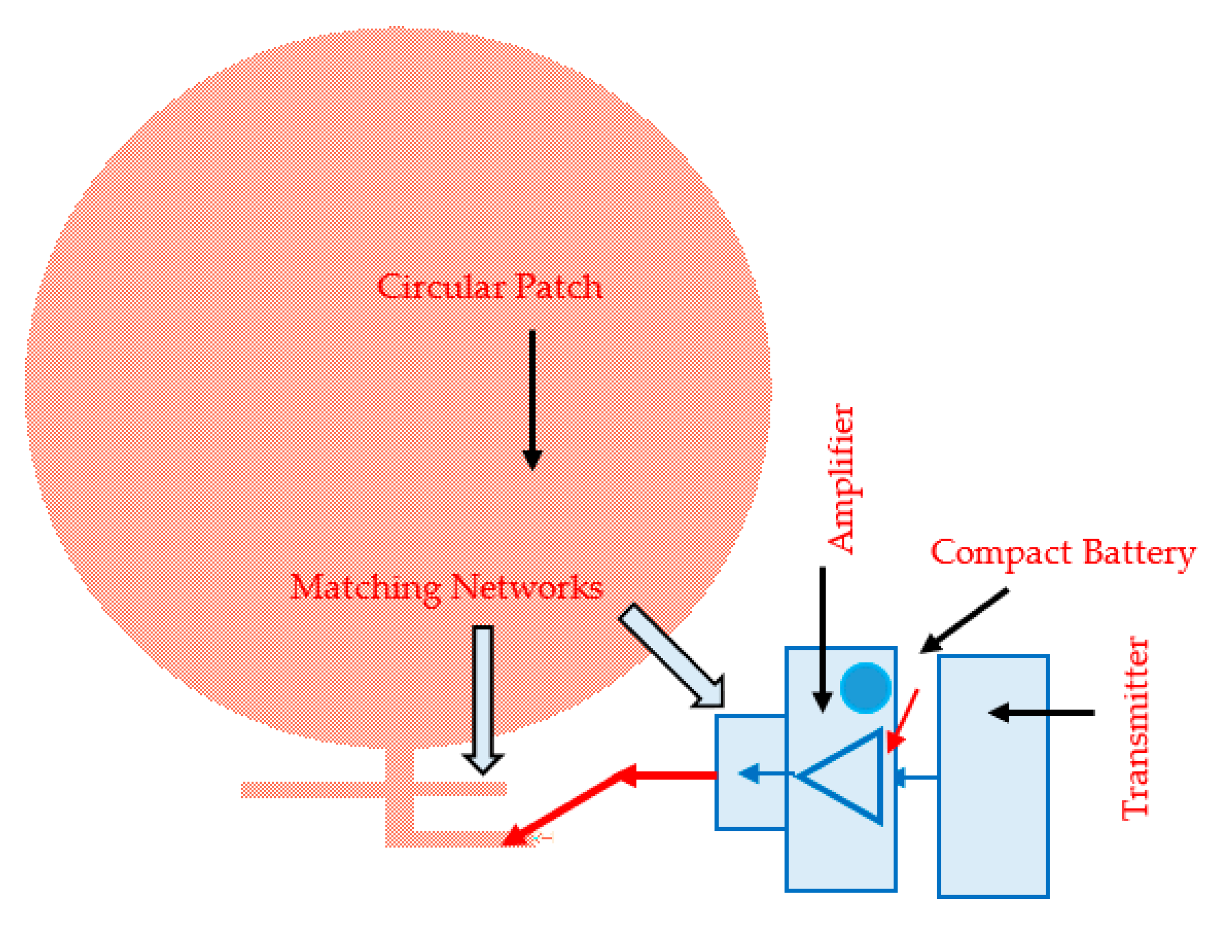
Figure 11.
Active Circular Transmitting Patch antenna for Internet of Things (IoT) and 5G Applications.
Figure 11.
Active Circular Transmitting Patch antenna for Internet of Things (IoT) and 5G Applications.
Figure 12.
S11 of Transmitting Circular Patch antenna.
Figure 12.
S11 of Transmitting Circular Patch antenna.
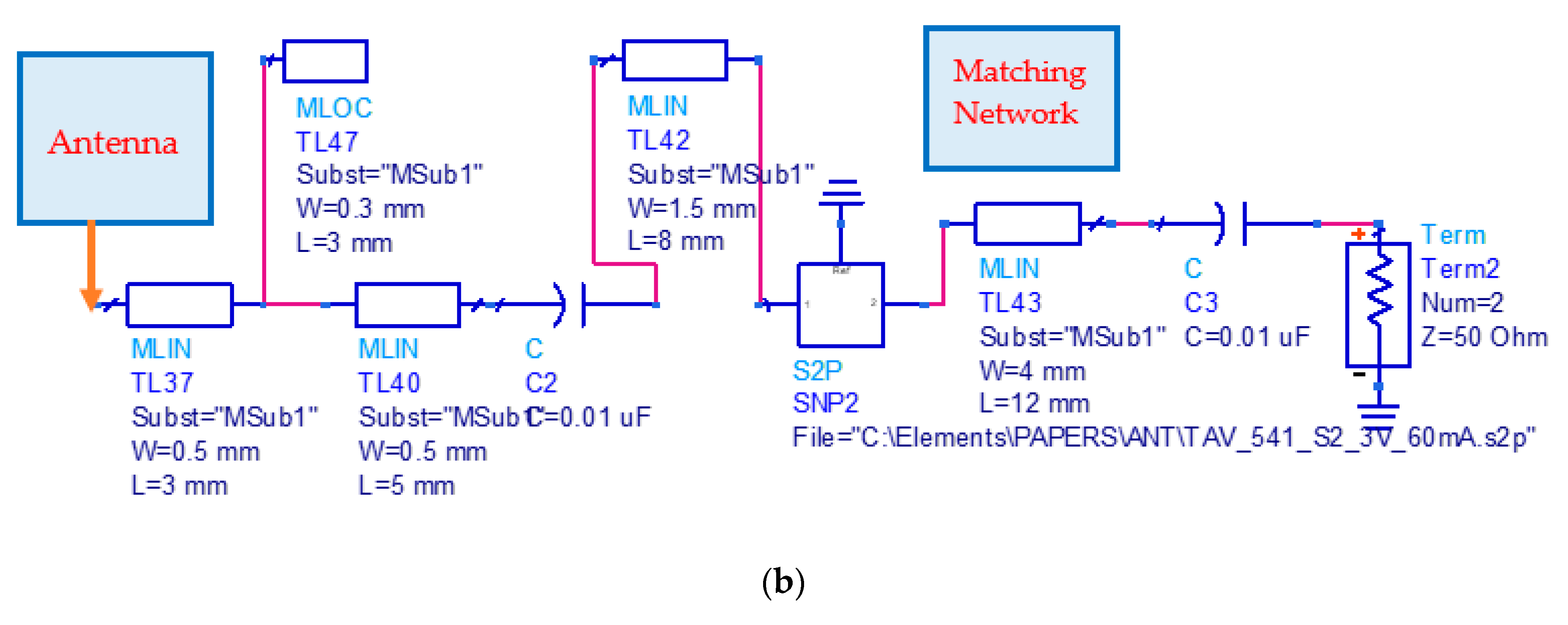
Figure 13.
Transmitting Circular Patch antenna: (a) Matching network; (b) S11 of the active antenna.
Figure 13.
Transmitting Circular Patch antenna: (a) Matching network; (b) S11 of the active antenna.
Figure 14.
S21 of an Active Transmitting Circular Receiving Patch antenna.
Figure 14.
S21 of an Active Transmitting Circular Receiving Patch antenna.
Figure 15.
Active Receiving Compact Double Layer Circular Patch Antennas.
Figure 15.
Active Receiving Compact Double Layer Circular Patch Antennas.
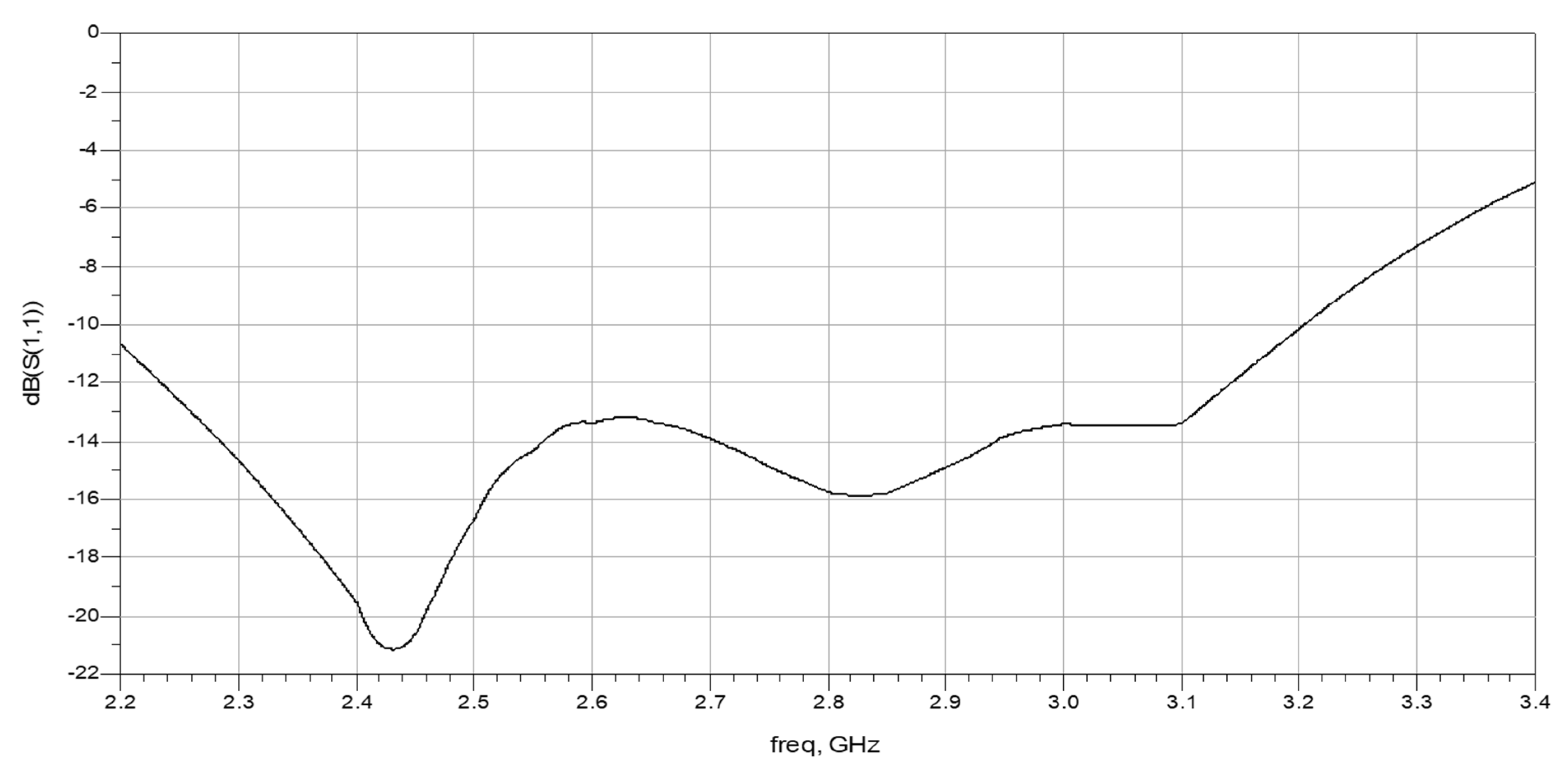
Figure 16.
Double layer active circular patch antenna S11 parameter on a human body.
Figure 16.
Double layer active circular patch antenna S11 parameter on a human body.
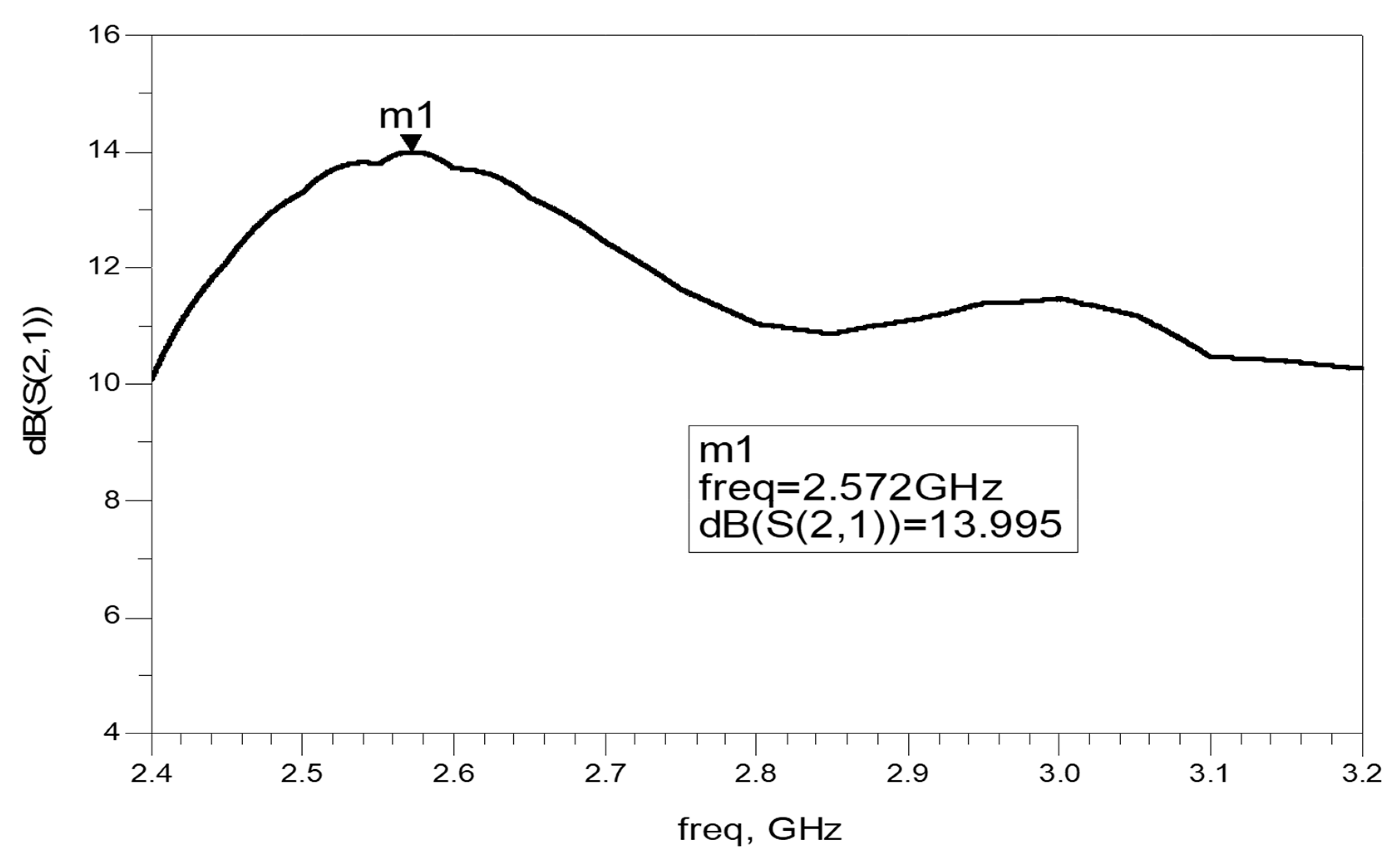
Figure 17.
S21 parameter on a human body of the Double Layer Active Circular Patch Antenna.
Figure 17.
S21 parameter on a human body of the Double Layer Active Circular Patch Antenna.
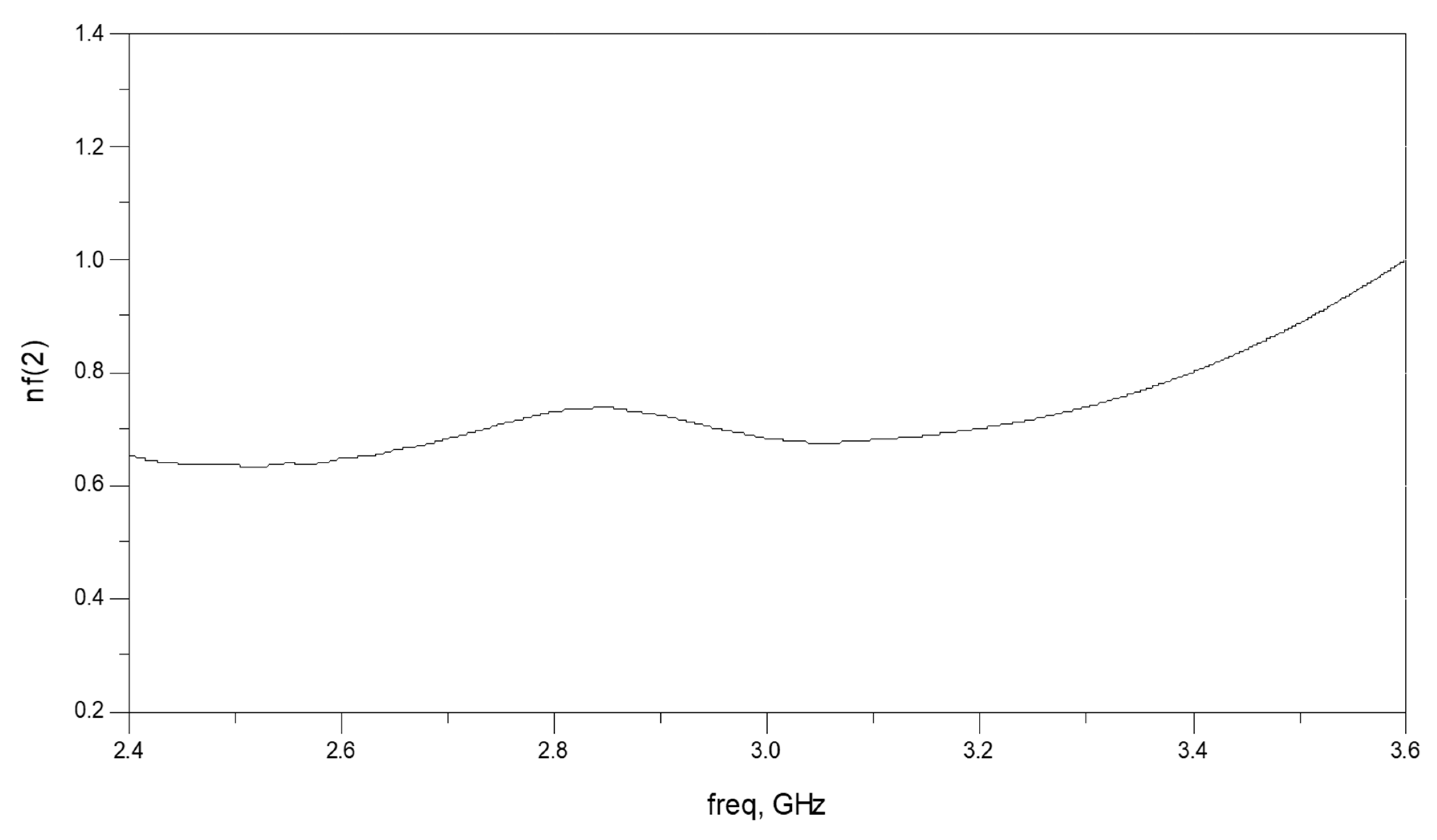
Figure 18.
Noise Figure of the Double Layer Active Circular Patch.
Figure 18.
Noise Figure of the Double Layer Active Circular Patch.
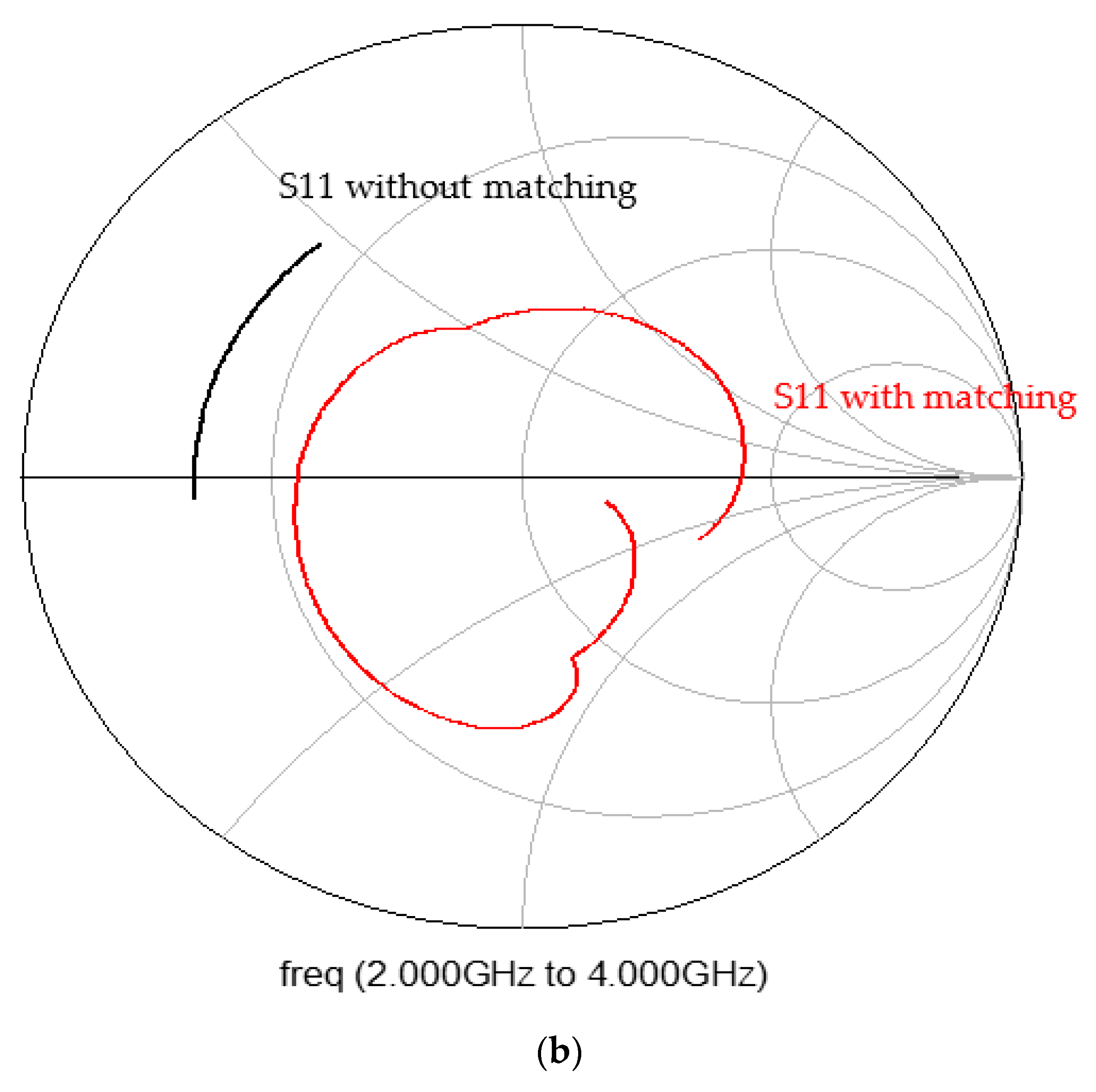
Figure 19.
Receiving Circular Patch antenna: (a) Matching network; (b) S11 of the active antenna.
Figure 19.
Receiving Circular Patch antenna: (a) Matching network; (b) S11 of the active antenna.
Figure 20.
S21 of an Active Stacked Circular Receiving Patch antenna.
Figure 20.
S21 of an Active Stacked Circular Receiving Patch antenna.
Figure 21.
Metamaterial Wearable Double Layer Circular Patch Antennas (a) Resonator; (b) Metamaterial Radiator; (c) Metamaterial Wearable Double Layer Circular Patch; (d) CSRRs Photo.
Figure 21.
Metamaterial Wearable Double Layer Circular Patch Antennas (a) Resonator; (b) Metamaterial Radiator; (c) Metamaterial Wearable Double Layer Circular Patch; (d) CSRRs Photo.
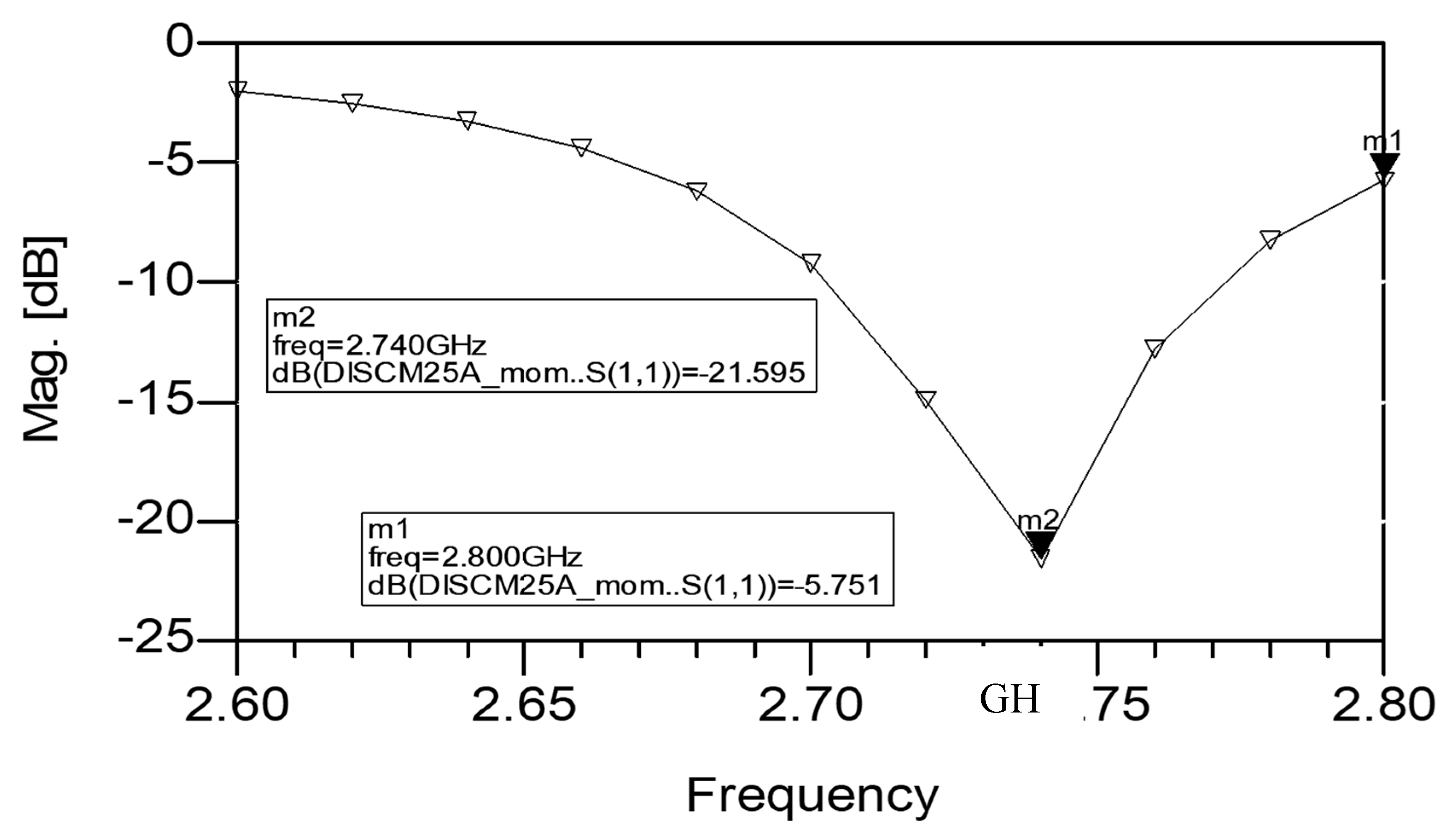
Figure 22.
S11 parameter on a human body of the Double Layer Circular Patch Antenna with CSRRs.
Figure 22.
S11 parameter on a human body of the Double Layer Circular Patch Antenna with CSRRs.
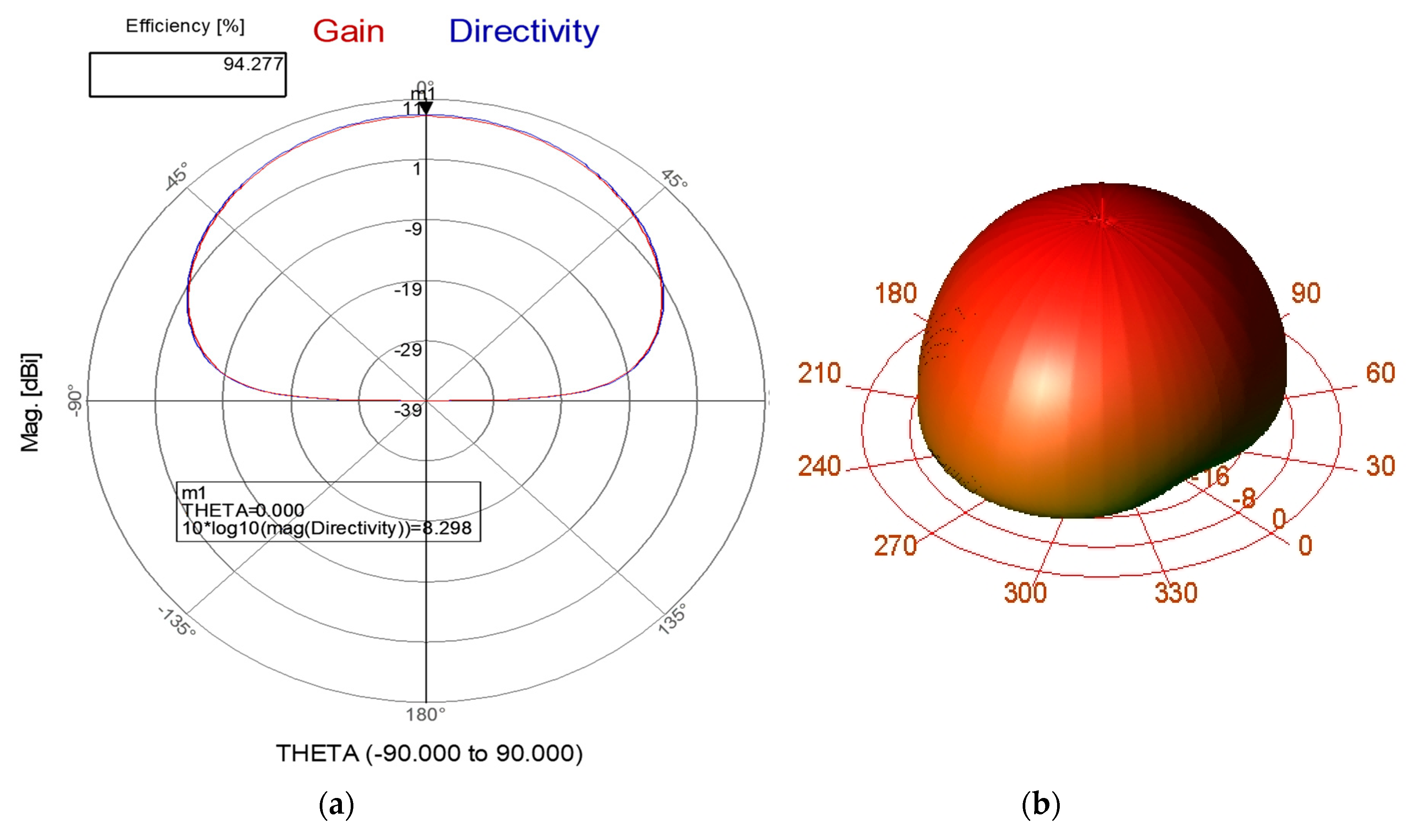
Figure 23.
(a) Radiation pattern of the Double Layer Circular microstrip antenna with CSRR at 2.7 GHz. (b) 3D radiation pattern of the Double Layer Circular patch antenna with CSRR.
Figure 23.
(a) Radiation pattern of the Double Layer Circular microstrip antenna with CSRR at 2.7 GHz. (b) 3D radiation pattern of the Double Layer Circular patch antenna with CSRR.
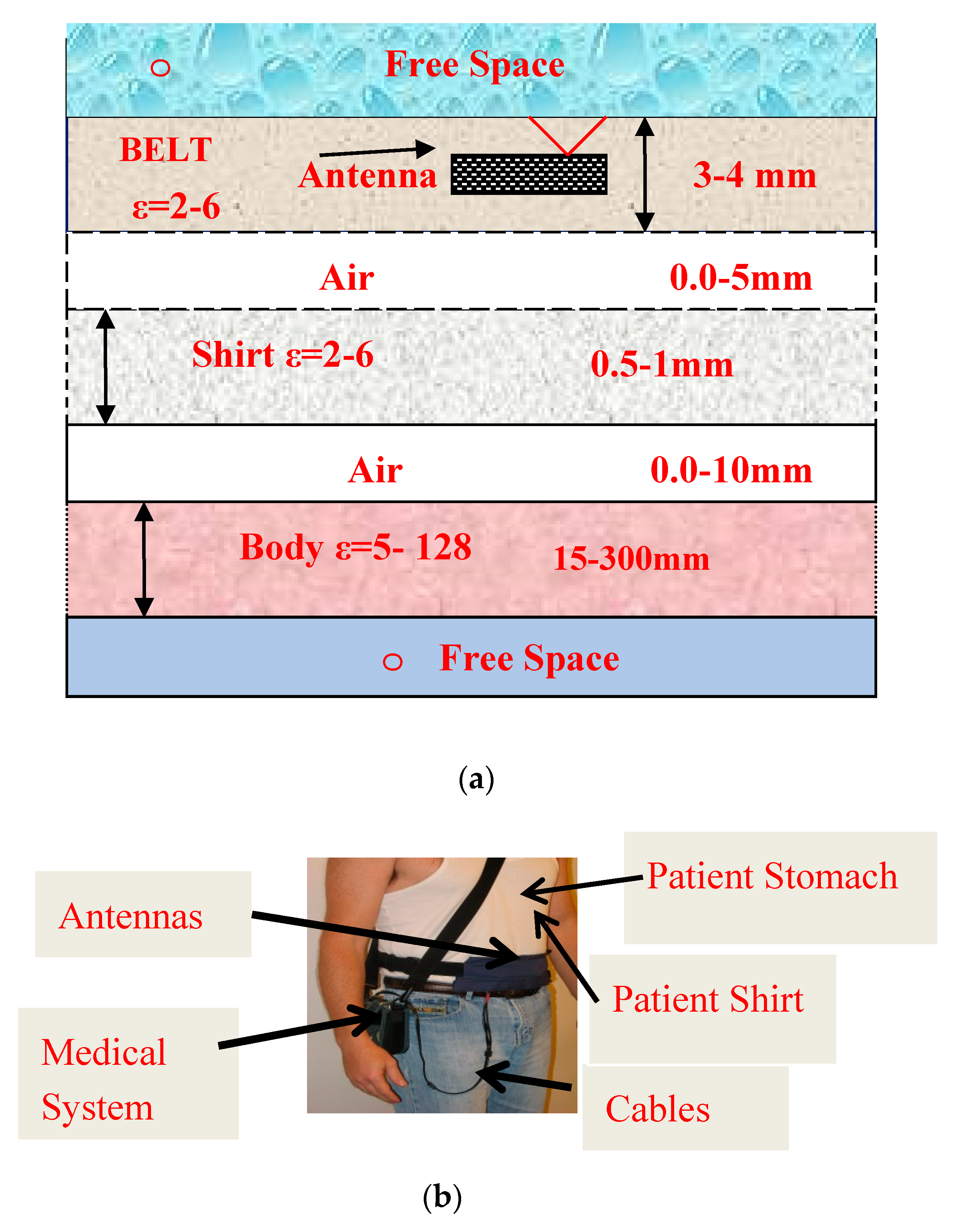
Figure 24.
(a) Wearable Antenna environment; (b) Wearable Medical System.
Figure 24.
(a) Wearable Antenna environment; (b) Wearable Medical System.
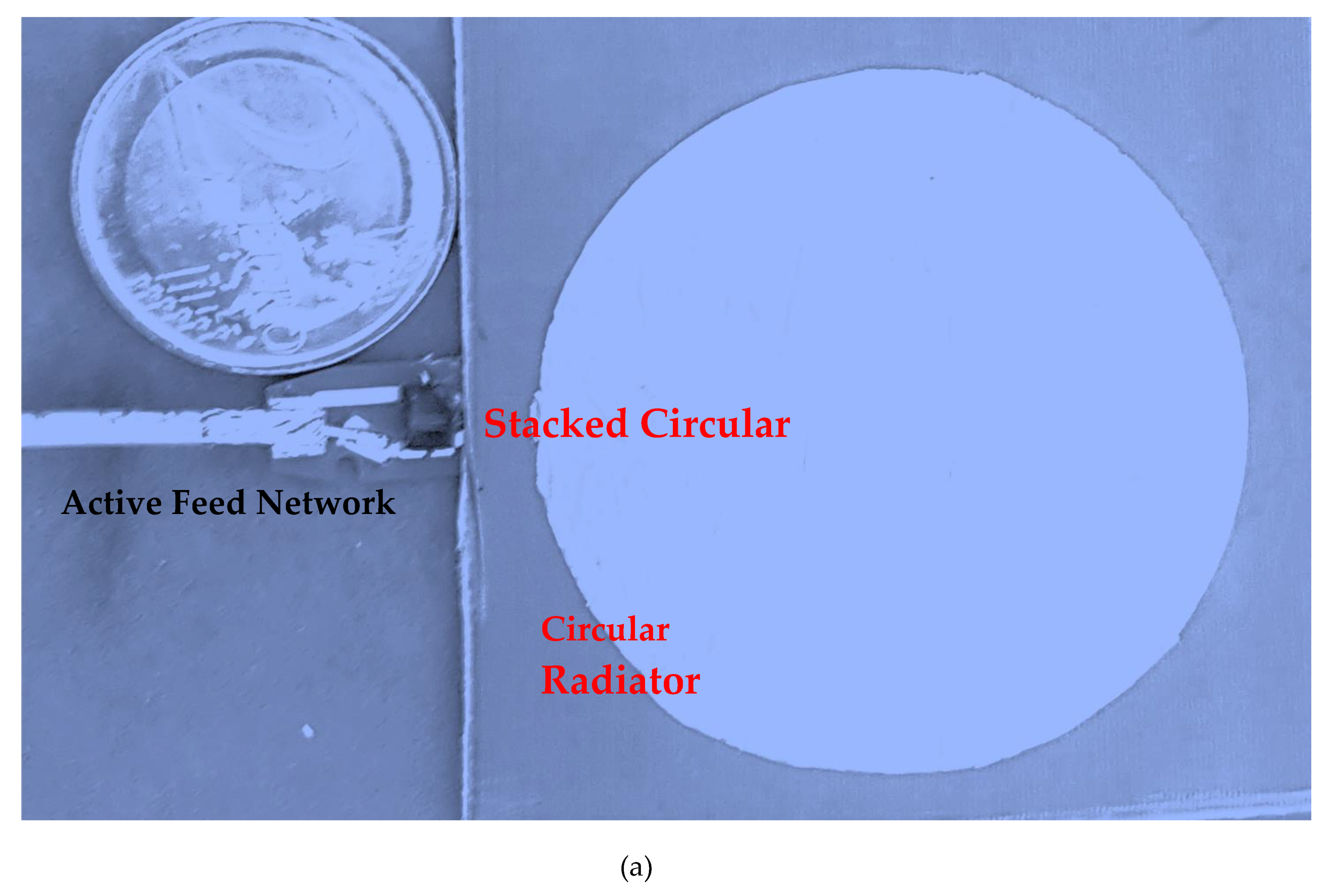
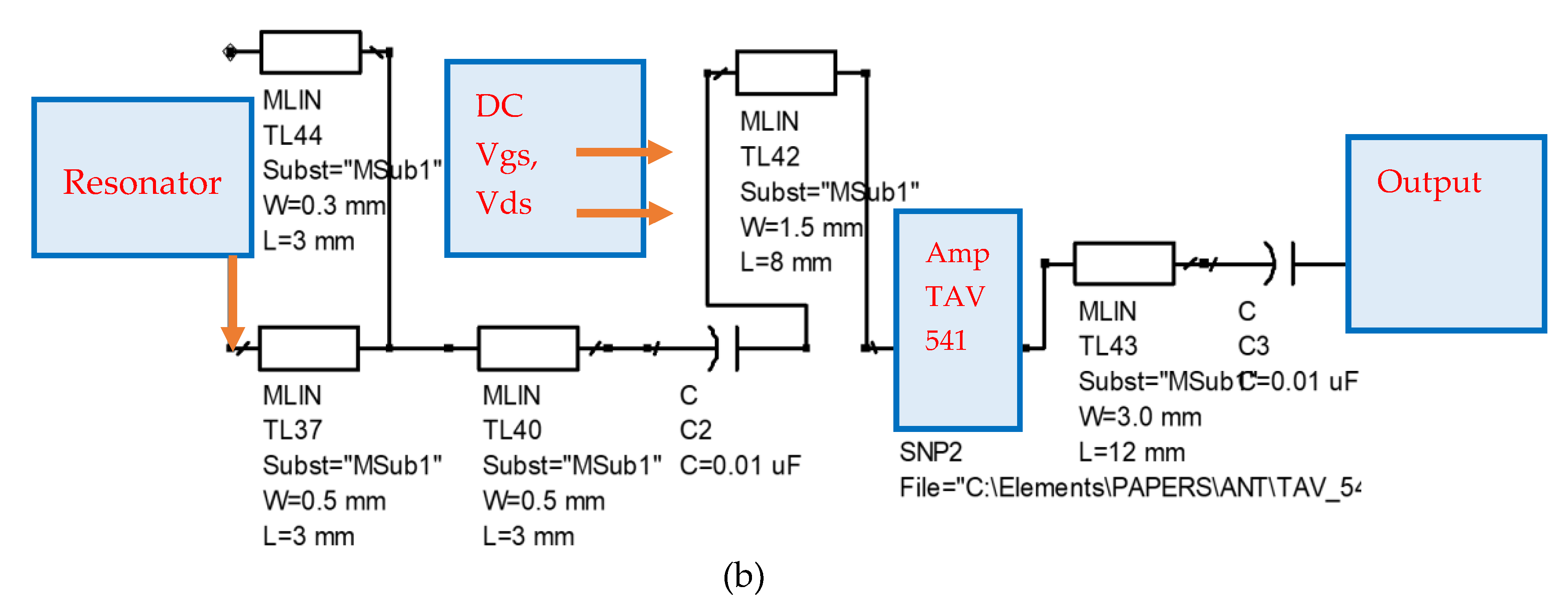
Figure 25.
(a) A photo of a prototype of the Active Stacked Circular Patch; (b) Antenna layout.
Figure 25.
(a) A photo of a prototype of the Active Stacked Circular Patch; (b) Antenna layout.
Figure 26.
Global Medical monitoring health system with WBAN and BAN Systems.
Figure 26.
Global Medical monitoring health system with WBAN and BAN Systems.
Table 1.
Low noise amplifier (LNA) specification at S band.
Table 1.
Low noise amplifier (LNA) specification at S band.
| Parameter | Specification | Remarks |
|---|
| Frequency range | 0.4–3 GHz | |
| Gain | 18 dB @2 GHz | Vds = 3 V; Ids = 60 mA |
| N.F | 0.5 dB @2 GHz | |
| P1dB | 19.1 dBm @2 GHz | |
| OIP3 | 33.6 dBm @2 GHz | |
| Max Input power | 17dBm | |
| Vgs | 0.48 V | |
| Vds | 3 V | |
| Ids | 60 mA | |
| Supply voltage | ±5 V | |
| Package | Surface Mount | |
| Operating Temperature | −40 °C–80 °C | |
Table 2.
LNA S parameters and noise parameters at the S band.
Table 2.
LNA S parameters and noise parameters at the S band.
| F-GHz | S11 | S11° | S21 | S21° | S12 | S12° | S22 | S22° |
|---|
| 1.04 | 0.74 | −126.2 | 12.74 | 100.13 | 0.05 | 33.69 | 0.29 | −94.96 |
| 1.21 | 0.71 | −137.6 | 11.25 | 92.91 | 0.051 | 30.05 | 0.26 | −104 |
| 1.53 | 0.687 | −154.2 | 9.30 | 82.06 | 0.055 | 26.08 | 0.22 | −119 |
| 1.75 | 0.67 | −164.1 | 8.24 | 75.31 | 0.06 | 23.14 | 0.20 | −128.4 |
| 2.02 | 0.67 | −174.6 | 7.30 | 67.82 | 0.06 | 20.88 | 0.18 | −138.8 |
| Noise Parameters |
| F-GHz | N. FMIN | N11X | N11Y | rn |
| 1 | 0.16 | 0.3424 | 52.98 | 0.042 |
| 1.9 | 0.30 | 0.368 | 100.93 | 0.03 |
| 2 | 0.32 | 0.371 | 106.01 | 0.03 |
| 2.4 | 0.39 | 0.383 | 125.79 | 0.03 |
| 3 | 0.48 | 0.400 | 153.93 | 0.036 |
| 3.9 | 0.63 | 0.430 | −167.3 | 0.06 |
| 5 | 0.81 | 0.465 | −125.53 | 0.11 |
Table 3.
High-power amplifier (HPA) specification at S band.
Table 3.
High-power amplifier (HPA) specification at S band.
| Parameter | Specification | Remarks |
|---|
| Frequency range | 0.4–2.5 GHz | |
| Gain | 17.8 dB @2 GHz | Vds = 5 V; Ids = 85 mA |
| N.F | 5.5 dB @2 GHz | |
| P1dB | 18.0 dBm @2 GHz | |
| OIP3 | 29 dBm @2 GHz | |
| Max. Input power | 10dBm | |
| Vgs | 0.48 V | |
| Vds | 5 V | |
| Ids | 85 mA | |
| Supply voltage | ±5 V | |
| Package | Surface Mount | |
| Operating Temperature | −40 °C–80 °C | |
Table 4.
High-power amplifier S parameters at the S band.
Table 4.
High-power amplifier S parameters at the S band.
| F-GHz | S11 dB | S11° | S21 dB | S21° | S12 dB | S12° | S22 dB | S22° |
|---|
| 1.6 | −12.8 | 134.3 | 18.3 | 123.3 | −44.2 | −93.4 | −18.9 | 113.7 |
| 1.8 | −14.3 | 101.2 | 17.9 | 83 | −43 | −86.3 | −22 | 69.5 |
| 2 | −16.5 | 61.8 | 17.3 | 43.5 | −40.4 | 94.6 | −27 | 6.42 |
| 2.16 | −18.5 | 22.1 | 16.8 | 12.9 | −38 | −105.5 | −27.8 | −70.2 |
| 2.4 | −19.4 | −53.9 | 15.7 | −31.8 | −36 | −128 | −22.2 | −147.2 |
| 2.56 | −17.7 | 99.7 | 15 | −60 | −34.6 | −145.6 | −19.3 | −179.4 |
| 2.7 | −15.7 | 131 | 14.3 | −84.3 | −33.8 | −160.3 | −17.5 | 158.1 |
| 2.86 | −13.7 | 159 | 13.5 | −111.1 | −33 | −177.7 | −16 | 134.7 |
| 3 | −12.2 | 179.1 | 12.7 | −134.1 | −32.4 | 167.4 | 15.2 | 116.3 |
Table 5.
Electrical properties of body tissues [
16,
17].
Table 5.
Electrical properties of body tissues [
16,
17].
| Tissue | Property | 430 MHz | 600 MHz | 1 GHz | 1.2 GHz |
|---|
| Small intestine | σ | 1.74 | 1.74 | 1.74 | 1.74 |
| ε | 128.1 | 128.1 | 128.1 | 128.1 |
| Fat tissues | σ | 0.045 | 0.05 | 0.054 | 0.058 |
| ε | 5.00 | 5 | 4.72 | 4.57 |
| Stomach tissues | σ | 0.67 | 0.75 | 0.96 | 0.97 |
| ε | 42.9 | 41.40 | 39.66 | 39.05 |
| Blood | σ | 1.72 | 1.78 | 1.91 | 1.98 |
| ε | 57.3 | 56.5 | 55.40 | 55.00 |
| Colon | σ | 1.00 | 1.05 | 1.30 | 1.44 |
| ε | 63.6 | 61.9 | 60.00 | 59.40 |
| Skin | σ | 0.57 | 0.6 | 0.63 | 0.76 |
| ε | 41.6 | 40.45 | 40.25 | 39.65 |
| Lung tissues | σ | 0.27 | 0.27 | 0.27 | 0.27 |
| ε | 38.4 | 38.4 | 38.4 | 38.4 |
| Kidney tissues | σ | 0.90 | 0.90 | 0.90 | 0.90 |
| ε | 117.45 | 117.45 | 117.45 | 117.45 |
Table 6.
Comparison between printed antennas with and without CSRR.
Table 6.
Comparison between printed antennas with and without CSRR.
| Antenna | Frequency (MHz) | BW % | Computed Gain dBi | Measured Gain dBi | Length.
(cm) | Efficiency % |
|---|
| Circular patch with CSRR | 2630 | 8 | 7.5 | 7.8 | 3.6 | 85 |
| Circular patch without CSRR | 2630 | 1.5 | 4.5 | 4.3 | 4.8 | 85 |
| Printed dipole with CSRR | 350 | 10 | 5.5 | 5.7 | 19.8 | 95 |
| Dipole without CSRR | 400 | 10 | 2.5 | 2.5 | 21 | 90 |
| Stacked circular patch with CSRR | 2700 | 8 | 8.5 | 8.4 | 4 | 95 |
| Stacked circular patch without CSRR | 2700 | 8 | 5.5 | 5.3 | 4.8 | 90 |
Table 7.
Comparison of electrical characteristics of wearable antennas [
1,
2].
Table 7.
Comparison of electrical characteristics of wearable antennas [
1,
2].
| Antenna | Frequency (GHz) | Bandwidth % | VSWR | Computed Gain dBi | Measured Gain dBi |
|---|
| Circular patch with CSRR | 2.63 | 8 | 2:1 | 75 | 7.8 |
| Active Circular Receiving Patch | 2.5 | 25 | 2:1 | 13.5 | 14.0 |
| Stacked circular patch with CSRR | 2.7 | 8 | 2:1 | 8.5 | 8.4 |
| Printed dipole [2] | 0.43 | 5–10 | 2:1 | 2–3 | 2–3 |
| Dipole with CSRR | 0.4 | 8–12 | 2:1 | 5–7 | 5–7 |
| Dipole (CSRR and strips) [2] | 0.35 | 50 | 2.5:1 | 5–7.5 | 5–7.5 |
| Loop [2] | 0.43 | 5–10 | 4:1 | 0 | 0 |
| Patch [2] | 2.2 | 1–3 | 2:1 | 2–3 | 2–3 |
| Stacked Patch [2] | 2.2 | 10–15 | 2:1 | 4–5 | 4–5 |
| Slot [2] | 2.5 | 50 | 2:1 | 3 | 3 |
| T shape slot [2] | 2.5 | 60 | 2:1 | 3 | 3 |
| Active slot | 2.5 | 40 | 3:1 | 12–20 | 12–21 |
| Active T slot | 2.5 | 50 | 3:1 | 12–20 | 12–21 |
| Active slot with CSRR [2] | 2.5 | 50 | 2.5:1 | 10–16 | 11–16 |
| Active Stacked Circular Patch | 2.5 | 25 | 2:1 | 12–14 | 11–15 |


