Abstract
In this article, experiments are realized in the flexible manufacturing system ICIM 3000 (FESTO, Germany), and its assembly system, located at the Institute of production technologies, Faculty of Material Sciences and Technologies, Slovak University of Technology. The assembly system is the final product assembled, and this process consists of five components. Unwanted inaccuracies in the assembly process of the elements, such as the insertion of thermometers and hygrometers into the base plate, usually arise. Based on these inaccuracies, we realize some experiments by the camera system SBOC-Q-R3-WB. This deals with the method of image processing. The camera system parameters are set-up. At the end of this contribution, a base of evaluated results is suggested and some minor design changes are realized in the assembly station. The goal of these changes is the higher reliability of the assembly process.
1. Introduction
Systems used for handling and transporting materials and products provide equipment transportation from one point to another. At the same time, they are a platform for automated data collection. Due to real-time information, producers can optimize energy and material consumption, labor, planning, maintenance, and other essential production indicators to be able to produce the right number of high-quality products and minimize unexpected costs.
Nowadays, CCTV systems are becoming part of flexible manufacturing systems often operated by industrial robots. Such next-generation manufacturing systems are often called intelligent manufacturing systems. They earned this name because they use some aspects of machine intelligence (perceive the surroundings, can adapt to some extent to changes in the external and internal environment, they can learn to some extent, and so on).
All these production trends create the need for the application of CCTV systems in scanning, sensing, and processing the images from the real world, which help solve the ever-increasing variety of industrial processes, monitoring, and delivery of goods while reducing costs [1]. CCTV scanning and image processing systems can be classified into a scientific discipline called “machine vision”. Machine vision is a new field of sensor technology that combines modern means of scanning and image digitizing with the processing realized by the effective computing technique. These scanning and image processing systems are produced in smaller sizes, but their performance, functionality, and undemanding use have increased [2]. In many cases, it is unnecessary to have specialized professional training for their setup and operation [1]. The main reason for the new trend in mentioned systems is the replacement of the traditional, discrete sensor systems for monitoring and scanning. In practice, it is not unique to see a combination of infrared 3D scanners with 2D cameras, which are used, for example, in the scanning of the box sizes, bad packing shape, and agriculture product quality [3,4,5]. In that way, it is very close to the evaluation of the reality that exists in human vision, such as what can be seen, controlled, measured, and evaluated. Nowadays, the application count of machine vision is continuously growing. The main reason for this growth is that machine vision applications can reduce business costs. Most customers require the delivery of products of high overall quality. It is awarded a fine for a defective part where the statistical assumption is not enough for the total control of quality. The only option is to control every item of the product. Very often, in practice, the only effective way to do this is to use the machine vision system. As has been mentioned in this article, automating visual inspection-based quality control processes are highly desirable for manufacturing companies as it significantly reduces manufacturing and can provide for greater accuracy in the monitoring of their manufacturing processes for different products [5,6,7,8].
1.1. Problem Description
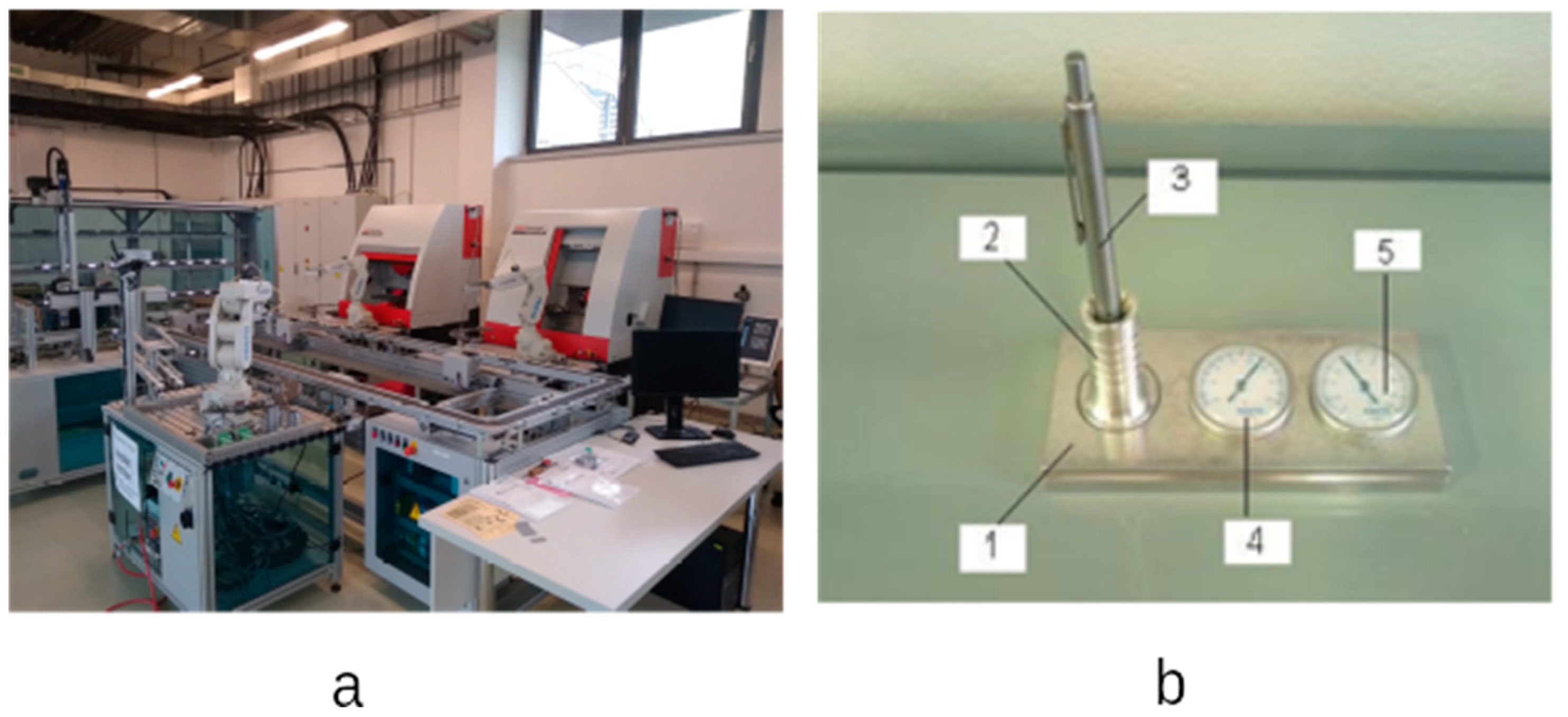
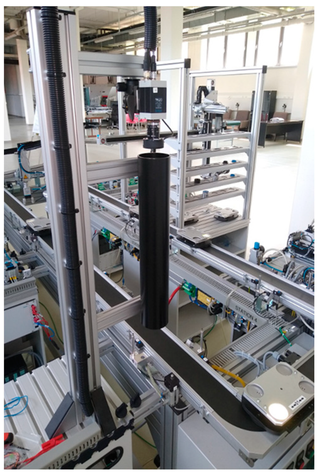
In our laboratory of Flexible Production Systems (Figure 1a), incorrectly assembled products (incorrectly rotated thermometer and hygrometer) are very common during robotic assembly. The camera system oversees the correct positioning of these two components. Each time the camera system is set-up, this problem does not occur for several hours, but the camera system needs to be set-up again after a few hours.
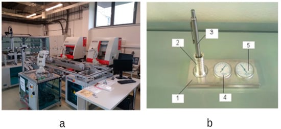
Figure 1.
Flexible production system and product. (a) Manufacturing assembly system ICIM 3000. (b) Parts of the final assembly composition: 1—a base plate, 2—a pen holder, 3—a pen, 4—thermometer, 5—hydrometer.
We assume that this problem is caused by inconsistent light from the surroundings, which changes during the day (morning, afternoon, evening) and according to the weather (sunny, cloudy).
1.2. Literature Review
The authors in [3] introduced the prototype of the machine vision station developed for quality grading of the star-shaped and rich-golden-color carambola fruits. A Fourier-based shape separation method was developed for shape grading, whereas color recognition was established using multivariate discriminant analysis. The Wilks’ lambda analysis was invoked to transform and compress the dataset comprising many interconnected variates to a reduced set of variates. A robust scaling normalization was introduced to achieve invariant geometrical transformations.
This study’s detailed image analysis and processing consisted of three groups: low-level processing, intermediate processing, and high-level processing. The first group includes image acquisition and preprocessing, such as image enhancement, extraction, and restoration. The second group is concerned with image transformation, such as RGB-to-HSI transformation, segmentation, and filtering. Finally, the third group involves recognition and interpretation.
The machine vision system inspected starfruit samples, and the results were compared to human judgment. Overall, the vision system correctly classified 100% of the starfruits for shape and 92% for color.
The other fruit quality control system based on machine vision was introduced [4]. They developed a robotic system for the automatic, nondestructive inspection and handling of fruit. The authors reported on the machine vision techniques developed at the Instituto Valenciano de Investigaciones Agrarias for the online estimation of the quality of oranges, peaches, and apples and to evaluate the efficiency of these techniques regarding the following quality attributes: size, color, stem location, and detection of external blemishes. Based on Bayesian discriminant analysis, the segmentation procedure allowed fruits to be precisely distinguished from the background. Thus, the determination of size was solved correctly. The colors of the fruits estimated by the system were well correlated with the colorimetric index values currently used as standards.
The image analysis was performed by a specific software application developed at IVIA. The system required previous off-line training. Using recorded images of fruit, an expert selected the different regions on the images and assigned all the pixels in every area to one of the pre-determined classes: background, primary color, secondary color, general damage type 1, general damage type 2, a specific feature, stem, and calyx. The classes were chosen to be used for all kinds of fruit used. The secondary color class was not used to train the system to segment those fruits with a single homogeneous color. The use of two classes for the general damage was justified because, for each fruit species, defects had different colors that could be separated as light and dark blemishes. Another pre-defined class was employed for detecting specific features of fruits, such as “russeting” for Golden delicious apples.
Good results were obtained in the location of the stem and the detection of blemishes. The classification system was tested online, with apples obtaining a good performance when classifying the fruit in batches and repeatability in blemish detection and size estimation of 86 and 93%, respectively.
In [9], the authors described the printed board inspection. It utilized an elimination-subtraction method that directly subtracted the template image from the inspected image and then conducted an elimination procedure to locate defects in the PCB. Each detected defect was subsequently classified into one of the seven defect types by three indices: the type of object detected, the difference in object numbers, and background numbers between the inspected image and the template.
The PCB automated inspection algorithm was tested using an actual PCB pattern on a PC/AT with a PCVISION-plus frame grabber. Polarized filters were used both in the lighting device and the camera lens to facilitate the quality of the images [9].
An actual PCB pattern was tested by the proposed method. All the defects were correctly detected.
The method is considered efficient for speed performance because only simple features are used to classify the defects. In addition, operations such as subtraction/elimination and counting the numbers of the objects (or backgrounds) in the inspected image and the template can be implemented by parallel processing, reducing the processing time substantially. Further, the PCB alignment problem can be solved by using an external mechanical fixture to aid positioning. Overall, the proposed automated PCB inspection method, independent of the size and composition of the inspected PCB pattern, is straightforward and effective [9].
In [10], the authors described production monitoring and control of the biscuit quality where the authors were dealing with the testing of the commercial biscuits by the machine vision system. Automation of visual quality control of the cookies and biscuits is essential for the companies that produce them. The financial matters are significantly reduced, higher accuracy is secured, and quality control is at a higher level. Physical properties, quality, and failures in baking the cookies are possible to detect by machine vision systems.
The metal ball surface error detection device was introduced by [11]. The proposed system can inspect the entire surface of a ball by capturing multiple greyscale images with two advanced CCD cameras as the ball rolls on an inclined rail. The specular reflectance of the metal surface is lessened by installing a shade around the ball. Defects are detected by comparing each captured image with its corresponding reference image.
Unlike the case of a flat metal surface, the reflectance by the spherical shape of a ball is nonuniform, which exacerbates the difficulty. The use of well-arranged illumination can effectively tackle this problem. For example, ring light illumination is used, and images are taken at varying distances between the light source and a metal ball. Any ball surface defect can be easily detected from a corresponding anomaly in the ring light image. One problem most existing systems possess is that it is difficult to satisfy the industry’s high-speed processing because some parts of the measurement systems usually need to be moved around a stationary ball for inspection [11].
Edge detection is a fundamental tool in image processing, machine vision, and computer vision, particularly in feature detection and feature extraction. It is also used in our case, and it is one of the crucial parts of object recognition, as can be seen in this paper. The authors of [12] studied and detected the edges using the vast difference in Gaussian filters applied on many different images with different sizes, and then measured the quality of images using the PSNR, MSE, and NAE.
Edge detection is the first stage in recouping data from images. Because of its importance, edge detection is a dynamic research region, producing a set of continuous curves that indicate the boundaries of objects when an edge detector is applied to a group of images. This situation is called ideal surface boundaries and curves corresponding to surface orientation interruptions. Data may be significantly reduced when using an edge detection algorithm on an image because it purifies important information and ignores less critical data. Still, it preserves the structural characteristics of the picture. Clarification of the original image’s information contents may be simplified if the edge detection step is successful [12].
The author in [13] spoke about the industrial application of an automated inspection system that aims to enhance the efficiency and flexibility of a computer-integrated manufacturing system (CIMS). A machine-vision-based approach was adopted to utilize its advantages of measurement flexibility, high resolution, and nondestruction. With a closed-loop feedback control architecture, the inspection procedures are fully integrated with the production process to detect and recover abnormal operations in a real-time mode.
In [14], the authors dealt with the general state of the art in machine vision. The authors presented the principle of image processing, the components of the system, and possible applications of machine vision in the present.
Despite the authors’ efforts, it was not possible to find an occurrence of a problem similar to our laboratory in the studied literature. Based on the mentioned literature, it is possible to compile general requirements that must be met for the successful use of a camera system for shape and color recognition.
Based on the knowledge from [3], multi-stage image processing and a suitable source of diffuse light are needed. The speed of image processing depends on the hardware used. These conditions at our workplace are met.
The findings of [4,11] confirm the previous claims. In addition, it can be seen from Figure 1 that the camera’s sensing space is closed to outside light. This condition is not met at our workplace (Figure 4), nor can it be, because the staff must have constant access to the work area (learning activities).
In [9,10], the authors emphasized the “training” of shape and color recognition software. We have dealt with this area repeatedly and thoroughly with each new camera setup at our workplace.
In the paper [11], two cameras were used simultaneously to eliminate unwanted light phenomena, and in addition, the entire area was covered. This solution is unsuitable for us.
Edge detection technology and multi-stage image processing are being developed in several studied literature sources ([3,12]). We use these technologies in our workplace, as shown in Figure 7.
Many study articles deal with various algorithms for image recognition, color, or edge detection ([15,16,17,18,19,20,21,22,23]) and their various modified variants. We decided to use standard algorithms built into our camera and which our software cooperating with the camera can solve reliably.
2. Materials and Methods
There is a production assembly system, ICIM 3000, in the laboratories of the Institute of Production Technologies at The faculty of Material Science and Technology at Slovak University of Technology. Within the assembly workstation of this production system, there is a camera system that enables the correct assembly (Figure 1a). At this workplace, the individual parts assemble into the final product (Figure 1b).
The ICIM 3000 is of the latest relevant solutions proposed by Festo Didactic for the training of students and the research center’s scientific needs in terms of manufacturing research. It is assumed to play an important role in illustrating complex topics such as production logistics and sequence planning in flexible manufacturing systems (FMS), as well as, at the same time, the material supply and disposal, and the planning algorithms for automated production lines.
There are a few reasons to believe the system is a step in advance of other similar ones in modularity, flexibility, and open ideas. Some of these are:
- Distributed intelligence is based on the concept of distributed control. All stations have their industrial controllers and can be operated stand-alone in the whole system network;
- Standard interfaces and communication. Most industrial-level components and subsystems such as CNC, robots, vision systems, and PLC are compatible;
- World-class CELL/LINE control concept.
It uses the most powerful factory integration software available, i.e., Casimir Control. This includes all SCADA features and more. A high-level process plan language makes it easy to define several processes at a time in a real multitasking operating system. The robust set of communication drivers makes it easy to integrate into most automation equipment brands.
Related to this, ICIM 3000 gives the user the chance to use either isolated modules or all of them simultaneously, being possible to incorporate modules as may be needed.
The system consists of two CNC processing centers, CONCEPT TURN 105 and CONCEPT MILL 105. It also includes a Flexible Robot Assembly Cell (FAC), two flexible robot feeders that carry out CNC-related loading/unloading operations, a quality station QH 200 with a pallet handling device where baseplates are checked for the diameter of the holes milled, a pallet conveyor system, and an Automatic Storage/Retrieval System (AS/RS).
Another possibility to create different desk sets is to assemble, for example, only one or no instrument or no pen. Thus, the several hundred variations are enough to perform experiments related to logistics, flexible assembly, and manufacturing.
The detailed description of this flexible manufacturing system (FMS) is in [24,25,26,27].
Despite being a new system, a few problems have been identified that are subject to be improved and worthy of in-depth analysis.
Simple changes in the environmental illumination affect the correct positioning and color identification of the objects (thermometer and hygrometer) in the baseplate. Thus, the camera software should often be manually adjusted, i.e., the exposure time to the available light conditions in the Checkkon software (Festo CheckKon Rel. 02 en 4.2) and new repositionings using the CheckOpti software [24].
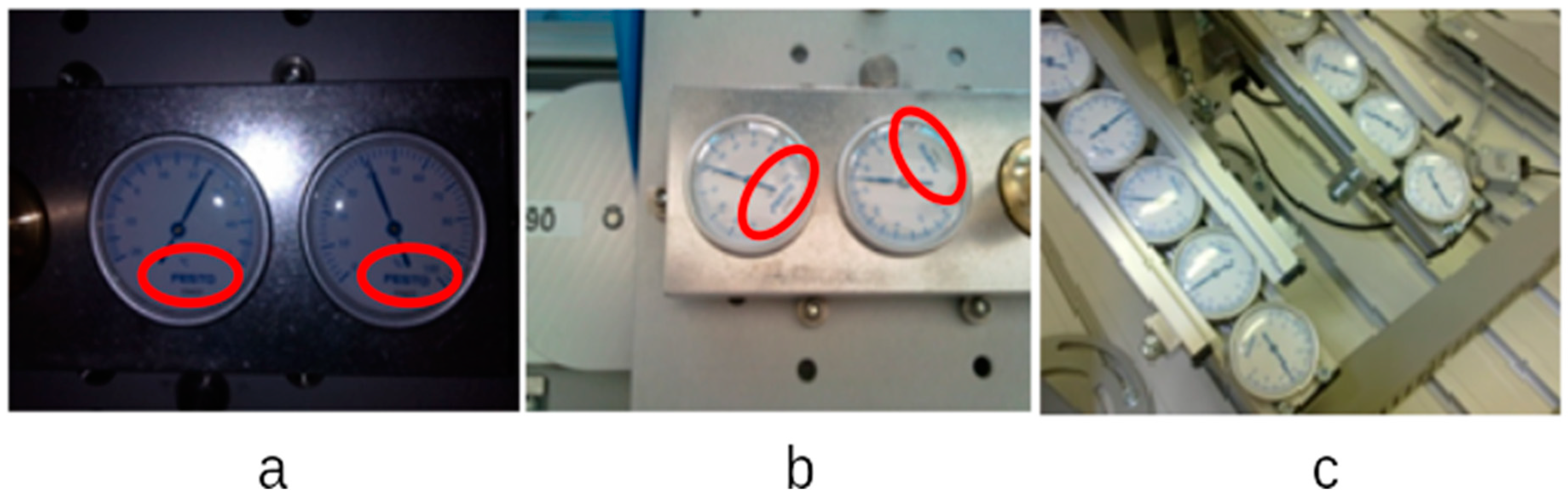
During assembling, the thermometer (Figure 1(b4)) and the hygrometer (Figure 1(b5)) should rotate, so that the inscription “FESTO” is aligned with the bottom edge of the base plate (Figure 1(b1) and Figure 5a). A closer look at these components is shown in Figure 2. These two components are almost identical.
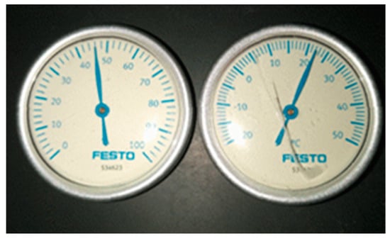
Figure 2.
Because of the hygrometer and thermometer, the inscription “FESTO” is the element to align with the edge of the base plate. These two parts are almost identical.
These components remain stored in two containers, Figure 5c, and their rotation is random. In the assembly process, the robot picks these parts from the magazine and places them in a jig under the camera, and the camera captures the rotation of the part (a smooth “FESTO” sign on the scanned image).
It evaluates the angular rotation of the piece and rotates the robot’s gripper according to this rotation as it takes a part from the jig under the camera and places it in the assembly [26,27].
Figure 3 shows the robotic assembly station and the camera detail. This assembly station can assemble numerous variants of the desk set product. The slightest alternative consists of two components (base plate, pen holder), while the maximum modification consists of 5 parts (+hygrometer, thermometer, pen). There are even more variants, as we have 22 options for the penholder and four modifications for the base plate. The robotic assembly station can assemble everything between these two extreme variants.
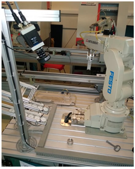
Figure 3.
Assembly station with camera.
From our point of view, only the maximum variant is interesting because, in this variant, the image recognition and the evaluation of the part rotation are used twice. Furthermore, when assembling this variant, there were problems with the orientation of components (thermometer, hygrometer).
Based on image recognition, the system determines the angle of actual rotation of the part, based on which the robot rotates its gripper at this angle and picks up the part. When the robot rotates its gripper with the picked-up part, the part is correctly positioned and inserted into the base. When image recognition fails, the robot does not rotate its gripper for the first or second time and inserts the part in the position it was picked up. Thus, the robot rotates its gripper to rotate the part to the correct position for assembly based on image recognition.
The assembly procedure is shown in a flowchart in Figure 4. In Figure 4a, we can see the whole assembly process flowchart. This flowchart represents the maximal assembly process. The robot puts together the maximal product and contains all five components. In the case of the simplest product that contains a smaller number of components, some of the operations are not realized.
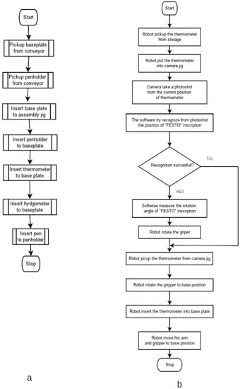
Figure 4.
The assembly process flowchart. (a) Assembly process, the problematic steps of “Insert thermometer” and “Insert hygrometer”. (b) The “Insert thermometer” process flowchart. In this flowchart, we can see that when object recognition is not successful, the robot does not rotate the gripper and puts the thermometer in the wrong position on the baseplate.
In Figure 4b, we can see a flowchart of the “Insert thermometer” procedure. This procedure must cooperate with the camera, object recognition software, and an industrial robot.
The part orientation at the storage is random (Figure 5c). When the robot places the part (thermometer) into the camera jig, this part rotation is random. The camera takes a photo shot from this part, and object recognition software tries to find the inscription “FESTO” in this picture and measure the rotation angle. If this task is finished successfully, the robot rotates the gripper and picks up the part from the camera jig, and after picking it up, the robot rotates the gripper to the base position. The part is rotated to the proper position for inserting into the baseplate (Figure 5a).
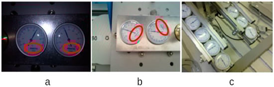
Figure 5.
(a) The location of the thermometer and hygrometer is in the correct position in the base plate. (b) Wrong rotation from the inserted thermometer and hygrometer to the base plate. (c) Thermometer and hygrometer stored in the buffers.
Suppose this object recognition task is finished unsuccessfully. In that case, the robot does not rotate the gripper before picking up the part from the camera jig and inserting that part in the wrong position into the baseplate (Figure 5b).
As mentioned in the assembly of a product containing thermometer and hygrometer components, in some cases, problems arose. Individually, these components were not rotated in the desired direction; the word “FESTO” was not aligned with the longer edge of the baseplate.
There have been frequent cases where up to 100% of assembled products were significantly defective (Figure 5b). We found that the camera needed to reset in this case, and after that, the rotation error was reset. However, after some time (the camera was set-up in the afternoon; the error rate was 100% the following day), the setting had to be repeated.
This is unacceptable for an intelligent manufacturing system operated by industrial robots. Among other solutions to this problem was a proposal to purchase another, higher-quality CCD camera. However, this proposal was cancelled partly for financial reasons and partly because no one could guarantee that this problem would not recur with another camera.
The research aimed to find out the cause of the assembly failure and propose a solution that will prevent the further occurrence of this problem.
Based on our previous experience [8,28,29], we assumed that the problem would be the inconsistency of the ambient lighting.
We decided to experimentally prove or disprove the assumption that inconsistency causes this problem in lighting conditions. We developed a preliminary plan to test various camera system settings under different lighting conditions. The realization of all planned experiments took a long time, as it was necessary to consider the natural light conditions. We always performed only two sets of measurements (current lighting conditions + camera set to previous lighting conditions and current lighting conditions + camera set to current lighting conditions). We chose the following reference conditions:
- (1)
- Present direct sunlight;
- (2)
- Afternoon shade, sunny day;
- (3)
- Daylight during a cloudy day;
- (4)
- Afternoon shade during a cloudy day;
- (5)
- Artificial lighting of the laboratory.
Our study also realized the quality evaluation experiments in the assembly process. This was realized by the same binary and highlighted edges method used in scanning hygrometers and thermometers inserted into the baseplate. It was necessary to set-up the CCTV systems SBOC-Q-R3-WB to eliminate inaccuracies in scanning. The procedure of individual steps used in the ICIM system is also described in this paper.
2.1. Description of the Used CCTV System
The aforementioned intelligent CCTV systems provide reliable results for a wide range of applications such as the orientation control of small parts, measuring rotating parts, fine positioning of drives, or localization of objects in the control of handling devices. This CCTV system is an ideal tool for measuring quality due to its compact design and light weight. These CCTV systems are characterized by simple integration and simple parameterization during commissioning. Up to 256 photo shots can be stored in the memory of CCTV systems, which provides maximal flexibility.
Excluding a sensor system for image detecting and processing, the complete electronic evaluation unit with interfaces (Ethernet/CANopen) for communication with a higher-level controller and programmable memory is built in these CCTV systems. The CCTV systems have a high sensitivity to light and a short exposure time. We adjusted and set the desired process realized through the software CheckKon and CheckOpti. The basic parameters of the CCTV systems can be seen in Table 1.

Table 1.
Parameters of CCTV systems SBOC-Q-R3-WB.
By using the CheckKon software, it is possible to monitor and edit all processes in CCTV systems (from image capture to input and output parameters):
- Selection of evaluation mode;
- Image capture and adjustment of the system parameters;
- Evaluation image of the last controlled parts;
- Image and registration of part test frames and derived test signs;
- Recording of new test programs;
- Documentation of the system.
In the program CheckOpti, after taking a model part, the user defines test characteristics that are chosen from the list and then places them on a model piece. There can be up to 64 properties in one test program that are optimized when taking the test parts.
Examples of test characteristics through the program CheckOpti:
- Vertical and vertical length;
- Measuring;
- Angle measurement, counting the events;
- Measuring of contours of the test piece;
- Determining the area;
- Calculation of greyscale or color deviations.
2.2. The CCTV Systems Setup Process
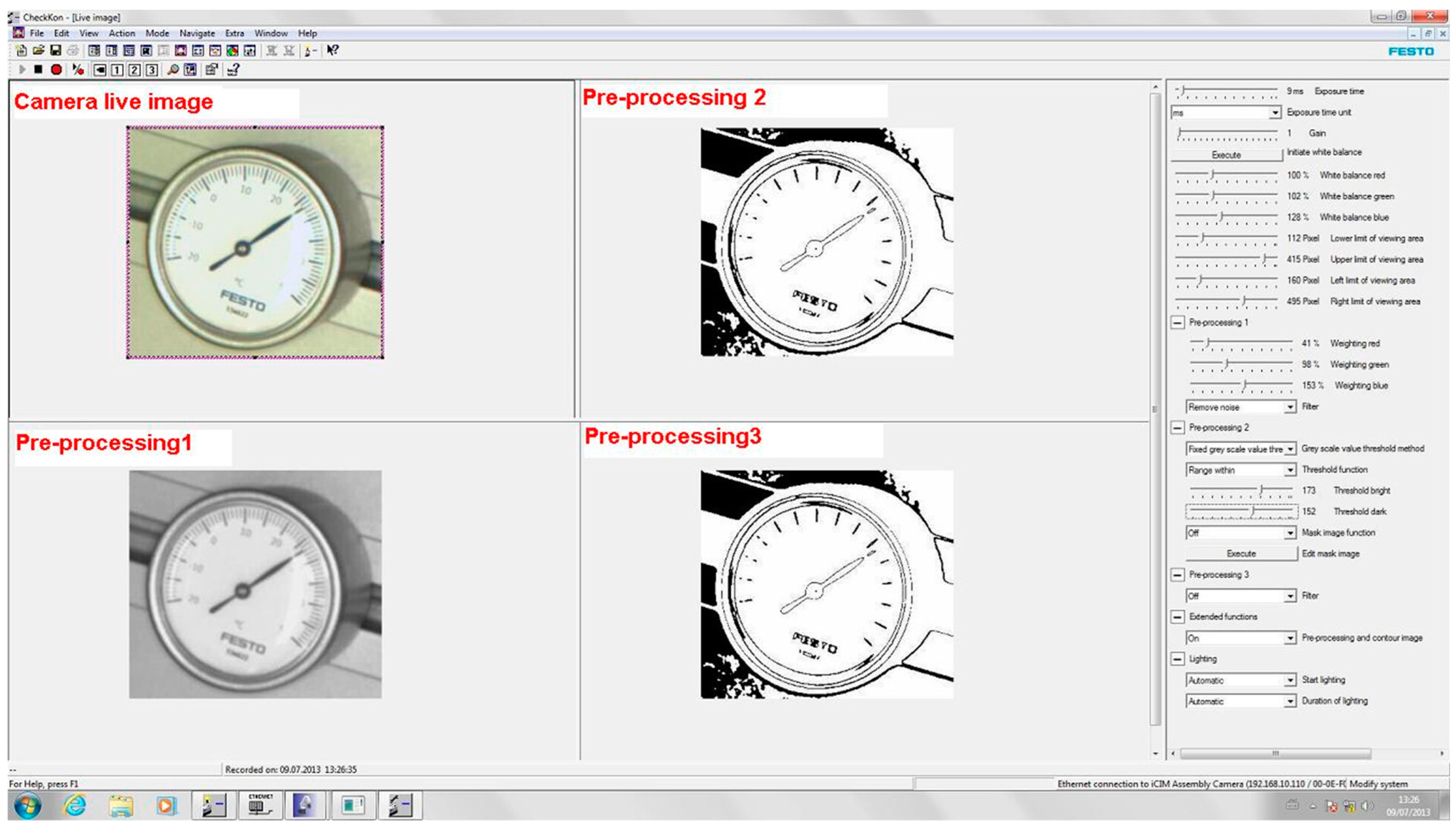
The live camera image of the model parts (thermometer, hygrometer) in the CCTV systems was re-scanned and then processed by software CheckKon. After, the CCTV systems must compare the scanned model part with the other test parts. In Figure 6, we can see the setting-up window for the software.
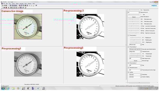
Figure 6.
General framework for the live image of the camera system.
The software gives not only live images from the CCTV systems but also other possibilities, so-called preprocessing 1, 2, 3 (as are shown in Figure 6):
- Preprocessing 1—live image converted to the shades of grey;
- Preprocessing 2, 3—grey shades image converted to white and black colors.
Experiments of similar types of themes have also been solved in the articles [12,26]. The CCTV system parameters were adjusted so that the requested object edges were highlighted mainly. This method of image processing substantially achieved image focusing. The edges were defined as the border between two areas of the image with different properties (in this case—brightness) [30].
After creating various pre-processings, the live image was stored in the software CheckKon. It was necessary to care about the inscription “FESTO”, placed on the thermometer and hygrometer, to be maximally highlighted in the digital image process of the model parts. The next step was to export the saved image from the camera to the software CheckOpti. The settings necessary for a given rotation of test parts by the assembly robot proceeded subsequently.
After all this, the following steps were followed:
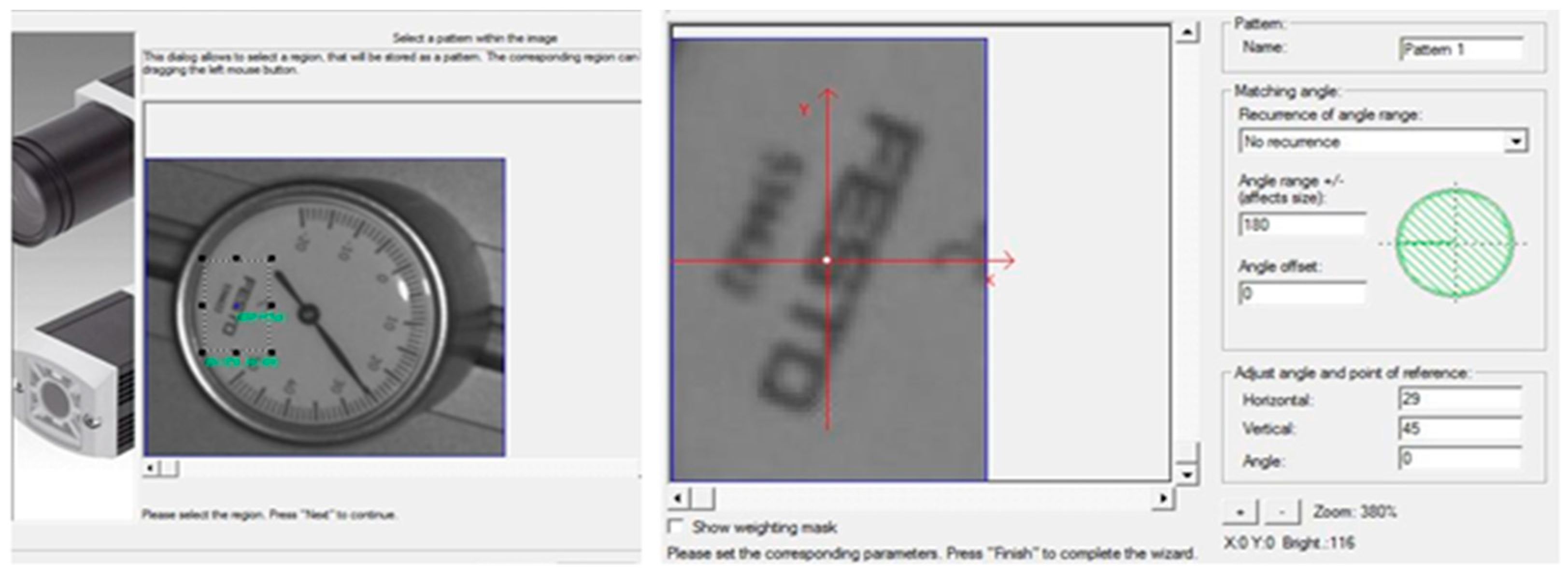
- It was necessary to choose an element on the model part according to which the CCTV systems would orientate in the control and scanning process. The main request was that test parts be inserted in the same way where the inscription would rotate in the same direction. That is why the inscription “FESTO” was used to compare, as shown in Figure 7.
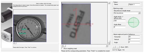 Figure 7. Example of the selection of an appropriate element on the model part for the comparing of the test parts by the camera system; an example of the area settings in search of the selected comparative element.
 - The next step was to set the area where the CCTV systems would look for comparative elements.
Thermometers and hygrometers are oriented in different ways in the buffers. At the same time, CCTV systems must look for mentioned elements (inscription “FESTO” on their entire surface) during comparison with the model part. Therefore, it was the reason to choose the whole test part surface area. After this, the robot receives a signal for correct rotation and insertion of test parts to the base plate. The shaded area of the whole circle depicts a surface of thermometers and hygrometers, as shown in Figure 7. After setting the required parameters of the CCTV systems and realizing the necessary steps, it is able to upload a model part with new parameters to the CCTV systems.
2.3. Experiment Preparation
Ambient light changed very intensely over time (the morning sun shines through the windows into the workspace, the afternoon is shaded there, and the artificial light in the evening). We assumed that these significant fluctuations in lighting conditions could cause the camera not to detect the image.
The essence of the expert was to set the camera according to the current lighting conditions and then mount 30 pieces of desk sets and record the success/correct rotation of the monitored components.
Subsequently, we assembled another set (30 pcs) of desk sets at another time (different lighting conditions), and again, we observed the correct orientation of the components.
We repeated this process under different conditions and at various camera settings.
As we mentioned earlier, the following reference conditions were chosen:
- (1)
- Present direct sunlight;
- (2)
- Afternoon shade, sunny day;
- (3)
- Daylight during a cloudy day;
- (4)
- Afternoon shade during a cloudy day;
- (5)
- Artificial lighting of the laboratory.
3. Results and Discussion
Using the software CheckOpti, ten new model parts were uploaded—thermometers 5× and hydrometers 5× under the same conditions (Software training).
In Table 2, we can see the experimental results. The rows represent different lighting conditions, and the columns represent camera system settings for given lighting conditions. The numerical designation of lighting conditions is in the previous chapter.
Table 2.
Experimental results.
The cells of the table show the number of correctly assembled pieces from the 30-piece batch for a given combination of lighting conditions and camera settings for specific lighting conditions.
As shown in the table, the product’s assembly can only be considered successful if the actual lighting conditions and camera settings match each other. Even then, in the case of artificial lighting, the assembly was not 100% successful.
The use of the light built into the camera did not affect the result.
The obtained results fully supported our assumptions about the reason for unsuccessful mounting at different times and the need to constantly reset the camera. Such an operation of the CCTV system during assembly is unacceptable in industrial practice.
The solution to the problem is to ensure sufficiently consistent lighting conditions in the workplace, regardless of the ambient lighting conditions.
In the first step, we solved this task by thoroughly covering all the laboratory windows and using only artificial lighting. The results of assembly success improved considerably but still did not reach the required 100% for a batch of 30 pieces.
Another possibility we considered was to completely cover the camera workstation and use the lighting built into the camera, possibly in combination with some kind of artificial light. In the case of industrial practice, this would be a possible solution, but in our case, this solution cannot be applied. Students must have access to the camera and see the system’s work. Covering the workplace is out of the question for us.
We chose the final solution to install the PVC pipe in front of the camera lens and use the built-in lighting. The upper end of this tube overlaps the edge of the lens, and the lower end is only a few millimeters at the top corner of the sensed component. In this way, only a minimum of disturbing sidelight reaches into the camera lens.
In this way, the assembly success rate increased to about 99%. This means that from a 30-piece batch, usually, 30 are good, which is sufficient for our purposes.
4. Conclusions
The presented paper solved the problems about the wrong positioning in the robotic assembly process, which arose in the final assembly in the assembly workspace with the camera control. These failures were found and observed in the product and insertion of thermometers and hygrometers into the base plate.
In the laboratory of intelligent manufacturing systems, a simple assembly of the desk set product was realized. These were a maximum of 5 parts that the robot must correctly assemble into one another. Two (hygrometer and thermometer) of the five components rotate and must be oriented correctly. The correct orientation of these components was ensured by a camera system that detects the current direction of the element and accordingly turns the robot’s gripper to insert the component into the assembly correctly.
There was a large part of the problem with incorrect assembly because these parts were not oriented correctly in the final product. Based on previous experience, we assumed that this would be due to inconsistent lighting conditions during the day in the laboratory. The lighting conditions in the laboratory during different parts of the day were so different that they prevented the camera system from working correctly.
Based on their previous experience, the authors had a theory that the cause could be unstable lighting at the beginning of the research. This theory was experimentally confirmed. Subsequently, the author proposed a solution to this problem and confirmed this solution experimentally again.
Experiments found by the tests confirmed this hypothesis, and based on this knowledge, we implemented measures to ensure sufficiently consistent conditions during assembly.
After the realization of individual proposals/designs, the improper part positioning of the system was eliminated, and the deviations in final assembly composition did not exist anymore.
The proposed solution’s improvement was also confirmed by the fact that the FMS manufacturer made changes to its equipment with camera systems based on this study and has been supplying them in the new models with the proposed solution since then (Figure 8).
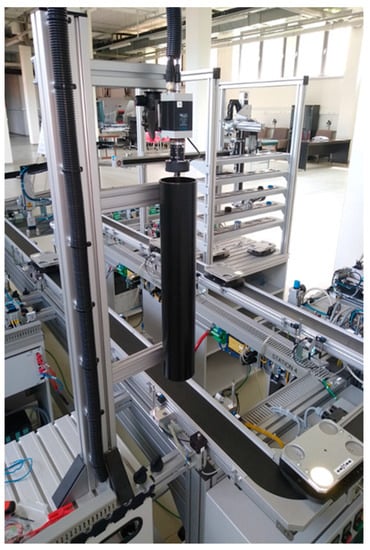
Figure 8.
The new device with proposed changes.
The authors’ contribution to knowledge is mainly in developing a basic and straightforward methodology for testing camera systems under different lighting conditions. This methodology examines the success/failure of image recognition under different lighting conditions and at various camera settings.
The systems of machine vision have a wide field of action from the control of size, shape, position, control of the complexity of parts in the assembly process, and identification of human faces. Therefore, intelligent CCTV systems are used; it is possible to exclude a person from the different parts of the production process, thus enhancing the work performance and the quality.
An urgent technical issue has been successfully resolved. In the future, we plan to focus on the field of vision systems on the measurement of geometric quantities using a CCD camera.
Author Contributions
Conceptualization, P.K. and S.-D.S.; methodology, V.P. and S.V.; software, V.P.; validation, P.K., S.-D.S. and S.V.; formal analysis, S.-D.S.; investigation, V.P.; resources, S.V.; data curation, S.-D.S. and S.V.; writing—original draft preparation, P.K.; writing—review and editing, P.K.; visualization, S.V.; supervision, P.K.; project administration, V.P.; funding acquisition, V.P. All authors have read and agreed to the published version of the manuscript.
Funding
This research was funded by KEGA 001STU-4/2022 “Support of the distance form of education in the form of online access for selected subjects of computer-aided study programs”.
Institutional Review Board Statement
Not applicable.
Informed Consent Statement
Not applicable.
Data Availability Statement
Not applicable.
Conflicts of Interest
The authors declare no conflict of interest.
References
- Sonka, M.; Hlava, V.; Boyle, R. Image Processing, Analysis and Machine Vision; Cengage Learning: Boston, MA, USA, 2014. [Google Scholar]
- Labudzki, R.; Legutko, S.; Raos, P. The essence and applications of machine vision. Teh. Vjesn. 2014, 21, 903–909. [Google Scholar]
- Abdullah, M.Z.; Fathinul-Syahir, A.S.; Mohd-Azemi, B.M.N. Automated inspection system for colour and shape grading of starfruit (Averrhoa carambola L.) using machine vision sensor. Trans. Inst. Meas. Control 2005, 27, 65–87. [Google Scholar] [CrossRef]
- Blasco, J.; Alexios, N.; Moltó, E. Machine Vision System for Automatic Quality Grading of Fruit. Biosyst. Eng. 2003, 85, 415–423. [Google Scholar] [CrossRef]
- Coulthard, M.A. Image processing for automatic surface defect detection. In Proceedings of the Third International Conference on Image Processing and Its Applications, Warwick, UK, 18–20 July 1989; IET: London, UK, 1989; pp. 192–196. [Google Scholar]
- Al-Kindi, G.A.; Baul, R.M.; Gill, K.F. An application of machine vision in the automated inspection of engineering surfaces. Int. J. Prod. Res. 1992, 30, 241–253. [Google Scholar] [CrossRef]
- Brosnan, T.; Sun, D.-W. Inspection and grading of agricultural and food products by computer vision systems—A review. Comput. Electron. Agric. 2002, 36, 193–213. [Google Scholar] [CrossRef]
- Danišová, N.; Zvolenskỳ, R.; Velíšek, K. Design additional check station with intelligent camera system. In Annals of DAAAM and Proceedings of DAAAM Symposium; DAAAM International: Vienna, Austria, 2008; ISSN 17269679. [Google Scholar]
- Wu, W.-Y.; Wang, M.-J.J.; Liu, C.-M. Automated inspection of printed circuit boards through machine vision. Comput. Ind. 1996, 28, 103–111. [Google Scholar] [CrossRef]
- Srivastava, S.; Boyat, S.; Sadistap, S. A Robust Machine Vision Algorithm Development for Quality Parameters Extraction of Circular Biscuits and Cookies Digital Images. J. Food Process. 2014, 2014, 376360. [Google Scholar] [CrossRef] [Green Version]
- Do, Y.; Lee, S.; Kim, Y. Vision-based surface defect inspection of metal balls. Meas. Sci. Technol. 2011, 22, 107001. [Google Scholar] [CrossRef]
- El-Sennary, H.A.E.-F.; Hussien, M.E.; Ali, A.E.-M.A. Edge Detection of an Image-Based on Extended Difference of Gaussian. Am. J. Comput. Sci. Technol. 2019, 2, 35–47. [Google Scholar] [CrossRef]
- Chen, F.L.; Su, C.T. Vision-based automated inspection system in computer integrated manufacturing. Int. J. Adv. Manuf. Technol. 1996, 11, 206–213. [Google Scholar] [CrossRef]
- Labudzki, R. The state of development of machine vision. Teh. Glas. 2011, 5, 109–114. [Google Scholar]
- Hassan, M.; Shaikh, M.S.; Jatoi, M.A. Image quality measurement-based comparative analysis of illumination compensation methods for face image normalization. Multimed. Syst. 2022, 28, 511–520. [Google Scholar] [CrossRef]
- You, H.; Tian, S.; Yu, L.; Lv, Y. Pixel-Level Remote Sensing Image Recognition Based on Bidirectional Word Vectors. IEEE Trans. Geosci. Remote Sens. 2020, 58, 1281–1293. [Google Scholar] [CrossRef]
- Xu, J.; He, X.; Ji, W. Mechanical System and Template-Matching-Based Position-Measuring Method for Automatic Spool Positioning and Loading in Welding Wire Winding. Appl. Sci. 2020, 10, 3762. [Google Scholar] [CrossRef]
- Sheryl, V.M. Error correction due to background subtraction in ratiometric calcium measurements with CCD camera. Heliyon 2020, 6, e04180. [Google Scholar] [CrossRef]
- Shi, Y.; Wang, S.; Zhou, S.; Kamruzzaman, M.M. Study on Modeling Method of Forest Tree Image Recognition Based on CCD and Theodolite. IEEE Access 2020, 8, 159067–159076. [Google Scholar] [CrossRef]
- Zou, Q.; Ni, L.; Wang, Q.; Li, Q.; Wang, S. Robust Gait Recognition by Integrating Inertial and RGBD Sensors. IEEE Trans. Cybern. 2018, 48, 1136–1150. [Google Scholar] [CrossRef] [Green Version]
- Yu, J.; Li, G.; Wang, S.; Lin, L. Employment of the appropriate range of sawtooth-shaped-function illumination intensity to improve the image quality. Optik 2018, 175, 189–196. [Google Scholar] [CrossRef]
- Zhang, W.; Zhao, Y.; Breckon, T.P.; Chen, L. Noise robust image edge detection based upon the automatic anisotropic Gaussian kernels. Pattern Recognit. 2017, 63, 193–205. [Google Scholar] [CrossRef] [Green Version]
- Rajathilagam, B.; Rangarajan, M. Edge detection using G-lets based on matrix factorization by group representations. Pattern Recognit. 2017, 67, 1–15. [Google Scholar] [CrossRef]
- Sobrino, D.R.D.; Košťál, P.; Vavruška, J. On the Analysis and Customization of an iCIM 3000 System: A Take on the Material Flow, Its Complexity and a Few General Issues to Improve. Appl. Mech. Mater. 2014, 474, 42–48. [Google Scholar] [CrossRef]
- Holubek, R.; Ružarovskỳ, R.; Velíšek, K. The Possibilities of the Communication Methods of iCIM 3000 System and Their Main Functions. Appl. Mech. Mater. 2013, 421, 585–590. [Google Scholar] [CrossRef]
- Koštál, P.; Mudriková, A. Laboratory for Drawingless Manufacturing. Res. Pap. Fac. Mater. Sci. Technol. Slovak Univ. Technol. 2018, 26, 145–149. [Google Scholar] [CrossRef] [Green Version]
- Košťál, P.; Delgado Sobrino, D.R.; Holubek, R.; Ružarovský, R. Laboratory of Flexible Manufacturing System for Drawingless Manufacturing. Appl. Mech. Mater. 2014, 693, 3–8. [Google Scholar] [CrossRef]
- Denisova, N.; Ruzarovsky, R.; Velisek, K. Design of Camera System Location at the Station for Loading and Orientation. Appl. Mech. Mater. 2013, 309, 27–34. [Google Scholar] [CrossRef]
- Danišová, N. Digital Image Processing in the Camera System of Assembly Systems ICIM. Appl. Mech. Mater. 2014, 474, 173–178. [Google Scholar] [CrossRef]
- Labudzki, R. The Use of Machine Vision to Recognize Objects. In Proceedings of the 34th International Conference on Production Engineering, Niš, Serbia, 28–30 September 2011. [Google Scholar]


Publisher’s Note: MDPI stays neutral with regard to jurisdictional claims in published maps and institutional affiliations. |
© 2022 by the authors. Licensee MDPI, Basel, Switzerland. This article is an open access article distributed under the terms and conditions of the Creative Commons Attribution (CC BY) license (https://creativecommons.org/licenses/by/4.0/).