
Design of A New Electromagnetic Launcher Based on the Magnetic Reluctance Control for the Propulsion of Aircraft-Mounted Microsatellites

 ,
,  ,
,
Abstract
:1. Introduction
- The launcher’s low efficiency is a challenging drawback, requiring effort to enhance the launcher’s efficiency.
- Many stages must be used to accelerate the projectile to ultra-high speed, making the launcher extremely long. For instance, Sandia researchers [4] designed very long barrels and solenoids to increase the projectile’s velocity. They built a 960 m long launcher that launched a package carrying a 600 kg satellite and a 1,220 kg boost rocket for orbital insertion with 2000 gees. And in [6], a NASA Langley coil cannon was created to accelerate massive beams to hypervelocity.
- Moreover, this kind of launcher cannot direct propel non-magnetic metals. In [17], a four-stage coil gun was developed to propel non-magnetic materials. They had to rapidly push the projectile before accelerating it with the developed gun.
- High magnetic reluctance which limits the number of flux lines and makes the user increase the current passes through the coil to achieve a certain number of flux lines.
- The current that passes through the coil is extremely high which requires high-power expensive electronic devices.
- Low saturation flux density of all ferromagnetic materials used for projectile manufacturing is a huge challenge.
- Launcher coil electrical resistance which consumes a considerable amount of energy.
- Eddy current is produced inside the projectile due to the presence of changing flux which will generate a backward force.
- Suck-back force limits the launcher efficiency, and it is a costly challenge.
- Launcher coil: this part generates the needed magnetic flux lines and has many parameters to control the number of these flux lines.
- Capacitor bank: this component stores a large amount of energy to discharge in the launcher coil to generate a time-changing current.
- Launching circuit: this circuit controls the current that passes from the capacitor to the launching coil by using a high-current thyristor and its firing circuit.
- Control circuit: this circuit is responsible for managing the charging time and firing signal to the thyristor and measuring the exit velocity.
- Launching a satellite from a flying launchpad may reduce many stresses on the satellite while launching. In addition, less money is required compared to building a massive launchpad on the ground to launch the satellites with the escape velocity of the Earth. Moreover, safety is ensured because the flying launchpad can safely launch satellites from anywhere. Finally, the percentage of success increases with the flying launchpad because it is near the low Earth orbit.
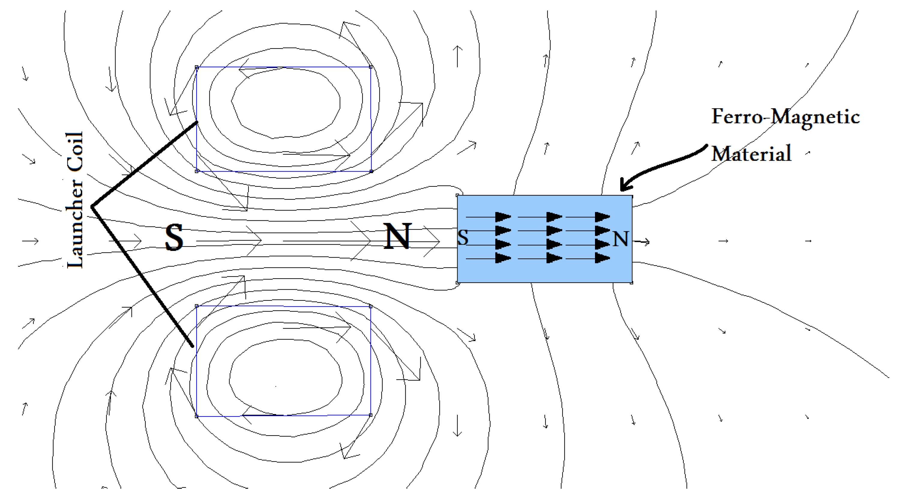
- Magnetic flux lines are strengthened, resulting in an increased number of aligned magnetic dipole moments. The increasing number of aligned magnetic dipole moments results in a higher attractive force.
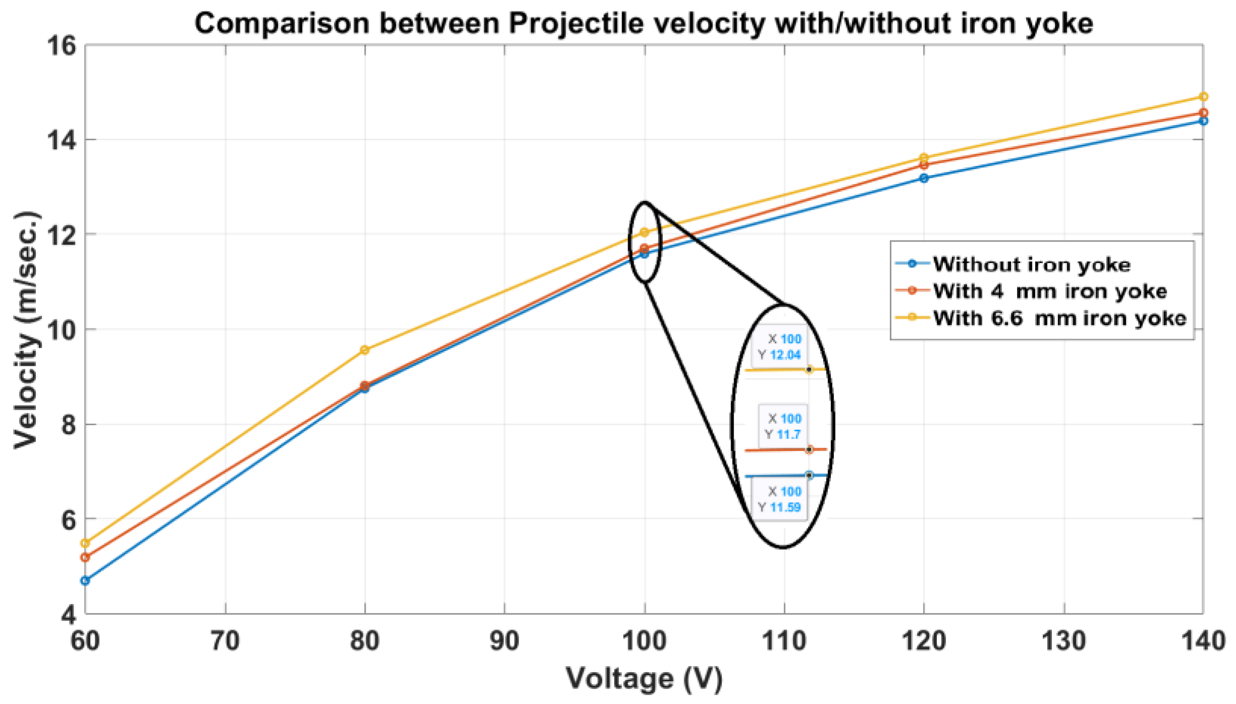
- The operating voltage required to achieve a pre-defined velocity is reduced. In other words, the voltage an ordinary launcher uses for the same speed is higher than the voltage a modified launcher needs. This may lead to a reduction of the required rated voltage of launching devices and lower the cost.
- Adding an iron yoke makes the magnetic path defined. The magnetic path length directly affects the coil inductance. Consequently, the deduction of a mathematical model for the system becomes smoother than before.
- Increase in the launcher weight.
- A velocity limitation due to low saturation flux density in the case of poor-permeability ferromagnetic materials.
- Energy loss due to eddy currents produced in the case of high-conductivity ferromagnetic materials.
2. A Microsatellite Launcher Fixed on Top of an Aircraft
3. Description of the Launcher System Modules
3.1. Launcher Coil
3.2. Power Circuit
3.3. Launching Circuit
3.4. Velocity-Measuring Module (Speedometer)
3.5. Voltage-Measuring Module
3.6. Control Panel
4. Theory of the Launcher System Design
4.1. Launcher Coil Modeling
4.2. Calculation of the Magnetic Force and Magnetic Circuit Reluctance
5. Description of the Operation Algorithm of the Launcher
6. Experimental Work
6.1. Verification of the Magnetic Dipoles Model
6.2. Examination of the New Design Performance
7. Discussion of the Results
7.1. Verification of the Magnetic Dipole Model
7.2. Examination of the New Design Performance
- Use a double twisted wire coil instead of a single wire coil.
- The projectile length set to the same value as the launcher coil length.
- A longitudinal laminated iron yoke added around the launcher coil with an area at least the same as the projectile cross-section area.
8. Future Work
- The authors of [25] deciphered the projectile material and shape issues. They found that a projectile made of radially laminated silicon steel sheets reduces the eddy current induced in the projectile. Therefore, this enhancement may give better efficiency if mixed with the proposed iron yoke launcher.
- The authors of [26] reduced the suck-back force by improving the discharge circuit of the launcher coil. Therefore, the combination of the modified iron yoke launcher and the improved discharge circuit deserves to be investigated.
- The authors of [24] reduced the suck-back force by using a conical-shapedcoil instead of the ordinary straight coil. Therefore, the design of a conical-shaped coil with an iron yoke is recommended to be examined.
9. Conclusions
Author Contributions
Funding
Data Availability Statement
Conflicts of Interest
Nomenclature
| Coil self-inductance (H) | |
| Coil internal resistance (0.125 Ω) | |
| External measuring resistance (0.07 Ω) | |
| Capacitor bank capacitance (F) | |
| The initial voltage of the capacitor bank (v) | |
| The reluctance of the magnetic circuit around the coil | |
| Length of the magnetic path | |
| The effective cross-section area of the coil | |
| Permeability of air | |
| Relative permeability of the material | |
| Number of turns of the coil | |
| Projectile acceleration | |
| v | Projectile velocity |
| Projectile mass | |
| b | Viscous coefficient |
| The kinetic energy of the projectile (J) | |
| Electrical energy stored in the capacitor bank | |
| Muzzle velocity |
References
- Hasirci, U.; Balikci, A. Design of an Electromagnetic Launcher for Earth-to-Orbit (ETO) microsatellite systems. In Proceedings of the 2009 4th International Conference on Recent Advances in Space Technologies, Istanbul, Turkey, 11–13 June 2009; pp. 233–236. [Google Scholar] [CrossRef]
- Lipinski, R.J. An electromagnetic induction launcher for Navy applications. Present. Hypervelocity Weapons Nav. Appl. Crit. Rev. Induction Launcher Technol. Meet. Albuquerque 1991, 26–27. [Google Scholar]
- Kaye, R.J.; Turman, B.N.; Shope, S.L. Applications of coilgun electromagnetic propulsion technology. In Proceedings of the Conference Record of the Twenty-Fifth International Power Modulator Symposium, 2002 and 2002 High-Voltage Workshop, Hollywood, CA, USA, 30 June–3 July 2002; pp. 703–707. [Google Scholar] [CrossRef]
- Lipinski, R.J.; Beard, S.; Boyes, J.; Cnare, E.C.; Cowan, M.; Duggin, B.W.; Kaye, R.J.; Morgan, R.M.; Outka, D.; Potter, D.; et al. Space applications for contactless coilguns. IEEE Trans. Magn. 1993, 29, 691–695. [Google Scholar] [CrossRef]
- Kaye, R.J.; Shokair, I.R.; Wavrik, R.W.; Dempsey, J.F.; Honey, W.E.; Shimp, K.J.; Douglas, G.M. Design and Evaluation of Coils for a 50 mm Diameter Induction Coilgun Launcher. IEEE Trans. Magn. 1995, 31, 478–483. [Google Scholar] [CrossRef]
- Schroeder, J.M.; Gully, J.H.; Driga, M.D. Electromagnetic launchers for space applications. IEEE Trans. Magn. 1989, 25, 504–507. [Google Scholar] [CrossRef]
- Orbach, Y.; Oren, M.; Golan, A.; Einat, M. Reluctance Launcher Coil-Gun Simulations and Experiment. IEEE Trans. Plasma Sci. 2019, 47, 1358–1363. [Google Scholar] [CrossRef]
- Kaye, R.J. Operational requirements and issues for coilgun electromagnetic launchers. IEEE Trans. Magn. 2005, 41, 194–199. [Google Scholar] [CrossRef]
- Mohamed, H.M.; Abdalla, M.A.; Mitkees, A.; Sabery, W. Overlapped Electromagnetic Coilgun for Low Speed Projectiles. J. Magn. 2015, 20, 322–329. [Google Scholar] [CrossRef]
- Abdo, T.M.; Elrefai, A.L.; Adly, A.A.; Mahgoub, O.A. Performance analysis of coil-gun electromagnetic launcher using a finite element coupled model. In Proceedings of the 2016 Eighteenth International Middle East Power Systems Conference (MEPCON), Cairo, Egypt, 27–29 December 2016; pp. 506–511. [Google Scholar] [CrossRef]
- Winarno, B.; Putra, R.G.; Yuwono, I.; Gunawan, A.I.; Sumantri, B. Control of Velocity Projectile on Multistage Coil gun. In Proceedings of the 2018 International Conference on Applied Science and Technology (iCAST), Manado, Indonesia, 26–27 October 2018; pp. 24–29. [Google Scholar] [CrossRef]
- Coramik, M.; Citak, H.; Bicakci, S.; Gunes, H.; Aydin, Y.; Ege, Y. Studies to Increase Barrel Exit Velocity for Four-Stage Coil-Gun. IEEE Trans. Plasma Sci. 2020, 48, 2618–2627. [Google Scholar] [CrossRef]
- Barandes, J.A. Can Magnetic Forces Do Work? arXiv 2019, arXiv:1911.08890. [Google Scholar]
- Wright, M.R.; Kuznetsov, S.B.; Kloesel, K.J. A lunar electromagnetic launch system for in situ resource utilization. IEEE Trans. Plasma Sci. 2011, 39, 521–528. [Google Scholar] [CrossRef]
- Mascolo, L.; Stoica, A. Electro-Magnetic Launchers on the Moon: A Feasibility Study. In Proceedings of the 2018 NASA/ESA Conference on Adaptive Hardware and Systems (AHS), Edinburgh, UK, 6–9 August 2018; pp. 37–42. [Google Scholar] [CrossRef]
- Einat, M.; Orbach, Y. A multi-stage 130 m/s reluctance linear electromagnetic launcher. Sci. Rep. 2023, 13, 218. [Google Scholar] [CrossRef] [PubMed]
- Cos, I. Optimization of parameters acting on a projectile velocity within a four stage induction coil-gun. Measurement 2010, 43, 1656–1660. [Google Scholar] [CrossRef]
- Barandes, J.A. On Magnetic Forces and Work. Found. Phys. 2021, 51, 79. [Google Scholar] [CrossRef]
- Liu, S.; Ruan, J.; Huang, D.; Wan, Z. Analysis of Inductive Coil Gun Performance Based on Field Coupling Circuit Method. In Proceedings of the 2009 IEEE 6th International Power Electronics and Motion Control Conference, Wuhan, China, 17–20 May 2009; Volume 3, pp. 845–849. [Google Scholar]
- Yadong, Z.; Ying, W.; Jiangjun, R. Capacitor-driven coil-gun scaling relationships. IEEE Trans. Plasma Sci. 2011, 39, 220–224. [Google Scholar] [CrossRef]
- Lee, S.J.; Kim, J.H.; Kim, S.H. Design and experiments of multi-stage coil gun system. J. Vibroengineering 2016, 18, 2053–2060. [Google Scholar] [CrossRef]
- Daldaban, F.; Sari, V. Design and implementation of a three-coil linear reluctance launcher. In Proceedings of the 2014 16th International Power Electronics and Motion Control Conference and Exposition, Antalya, Turkey, 21–24 September 2014; pp. 1084–1088. [Google Scholar] [CrossRef]
- Naseradinmousavi, P.; Nataraj, C. Nonlinear mathematical modeling of butterfly valves driven by solenoid actuators. Appl. Math. Model. 2011, 35, 2324–2335. [Google Scholar] [CrossRef]
- Abdo, M.M.; Fanni, M.; Miyashita, T.; Ahmed, S.M. The Effect of Coil Geometry and Winding Method on the Electromagnetic Launcher Performance. In Proceedings of the IECON 2022—48th Annual Conference of the IEEE Industrial Electronics Society, Brussels, Belgium, 17–20 October 2022; pp. 1–5. [Google Scholar]
- Deng, H.; Wang, Y.; Yan, Z.M. Study on the influence of armature on the efficiency of reluctance accelerator. Def. Technol. 2021, 18. [Google Scholar] [CrossRef]
- Deng, H.; Wang, Y.; Lu, F.; Yan, Z. Optimization of reluctance accelerator efficiency by an improved discharging circuit. Def. Technol. 2020, 16, 662–667. [Google Scholar] [CrossRef]
- Zandi, S.; Seresht, M.J.; Khan, A.; Gorji, N.E. Simulation of heat loss in Cu2ZnSn4SxSe4−x thin film solar cells: A coupled optical-electrical-thermal modeling. Renew. Energy 2022, 181, 320–328. [Google Scholar] [CrossRef]
- Available online: https://www.nasa.gov/feature/cygnss-microsatellites-prepared-for-air-launch-aboard-pegasus-xl-rocket (accessed on 7 August 2017).


| Coil Parameters | Values |
|---|---|
| Coil length | 20 mm |
| Number of turns | 100 turns |
| Inner diameter | 15 mm |
| Wire diameter | 2 × 0.8 mm |
| Resistance of the coil | 0.125 Ω |
| Input Voltage | 12 VDC |
| Output voltages | 350 VDC |
| 5 VDC | |
| 12 VDC | |
| 12 VDC | |
| 6 VDC | |
| Capacitor bank | 5000 μF/450 VDC |
| Temp. | Voltage | Capacitor | Coil Length | Projectile Length |
|---|---|---|---|---|
| 20 C | 100 V | 5 mF | 20 mm | 20 mm |
| Projectile Material | Velocity (m/s) |
|---|---|
| Iron (medium carbon) | 11.59 |
| Copper | Near zero |
| Aluminum | Near zero |
| Temp. | Capacitor | Coil Length | Projectile Mass | Projectile Length |
|---|---|---|---|---|
| 20 °C | 5 mF | 20 mm | 12.3 gm | 20 mm |
| Cap. Voltage | Velocity (m/s) | |||||
|---|---|---|---|---|---|---|
| without Iron Yoke | 4 mm Iron Yoke | 6.6 mm Iron Yoke | without Iron Yoke | 6.6 mm Iron Yoke | ||
| 60 v | 4.7 | 5.19 | 5.49 | 1.509 | 2.06 | 36.5 |
| 80 v | 8.75 | 8.81 | 9.56 | 2.942 | 3.512 | 19.37 |
| 100 v | 11.59 | 11.7 | 12.04 | 3.3 | 3.566 | 8 |
| 120 v | 13.18 | 13.46 | 13.61 | 2.967 | 3.164 | 6.63 |
| 140 v | 14.39 | 14.56 | 14.9 | 2.6 | 2.78 | 6.92 |
| Capacitor Voltage | ||
|---|---|---|
| 60 v | 4.7 | - |
| 80 v | 8.75 | 0.2025 |
| 100 v | 11.59 | 0.142 |
| 120 v | 13.18 | 0.0795 |
| 140 v | 14.39 | 0.0605 |
Disclaimer/Publisher’s Note: The statements, opinions and data contained in all publications are solely those of the individual author(s) and contributor(s) and not of MDPI and/or the editor(s). MDPI and/or the editor(s) disclaim responsibility for any injury to people or property resulting from any ideas, methods, instructions or products referred to in the content. |
© 2023 by the authors. Licensee MDPI, Basel, Switzerland. This article is an open access article distributed under the terms and conditions of the Creative Commons Attribution (CC BY) license (https://creativecommons.org/licenses/by/4.0/).
Share and Cite
Abdo, M.M.M.; El-Hussieny, H.; Miyashita, T.; Ahmed, S.M. Design of A New Electromagnetic Launcher Based on the Magnetic Reluctance Control for the Propulsion of Aircraft-Mounted Microsatellites. Appl. Syst. Innov. 2023, 6, 81. https://doi.org/10.3390/asi6050081
Abdo MMM, El-Hussieny H, Miyashita T, Ahmed SM. Design of A New Electromagnetic Launcher Based on the Magnetic Reluctance Control for the Propulsion of Aircraft-Mounted Microsatellites. Applied System Innovation. 2023; 6(5):81. https://doi.org/10.3390/asi6050081
Chicago/Turabian StyleAbdo, Mohamed Magdy Mohamed, Haitham El-Hussieny, Tomoyuki Miyashita, and Sabah M. Ahmed. 2023. "Design of A New Electromagnetic Launcher Based on the Magnetic Reluctance Control for the Propulsion of Aircraft-Mounted Microsatellites" Applied System Innovation 6, no. 5: 81. https://doi.org/10.3390/asi6050081
APA StyleAbdo, M. M. M., El-Hussieny, H., Miyashita, T., & Ahmed, S. M. (2023). Design of A New Electromagnetic Launcher Based on the Magnetic Reluctance Control for the Propulsion of Aircraft-Mounted Microsatellites. Applied System Innovation, 6(5), 81. https://doi.org/10.3390/asi6050081