Article

Design of A New Electromagnetic Launcher Based on the Magnetic Reluctance Control for the Propulsion of Aircraft-Mounted Microsatellites

by
Mohamed Magdy Mohamed Abdo
1,*,
Haitham El-Hussieny
1,*,
Tomoyuki Miyashita
2 and
Sabah M. Ahmed
1
1
Department of Mechatronics and Robotics Engineering, School of Innovative Design Engineering, Egypt-Japan University of Science and Technology, Alexandria 21934, Egypt
2
Department of Modern Mechanical Engineering, Faculty of Science and Engineering, Waseda University, Tokyo 169-8050, Japan
*
Authors to whom correspondence should be addressed.
Appl. Syst. Innov. 2023, 6(5), 81; https://doi.org/10.3390/asi6050081
Submission received: 22 July 2023 / Revised: 21 August 2023 / Accepted: 31 August 2023 / Published: 11 September 2023

Abstract

:
Recent developments in electromagnetic launchers have created potential applications in transportation, space, and defense systems. However, the total efficiency of these launchers has yet to be fully realized and optimized. Therefore, this paper introduces a new design idea based on increasing the magnetic flux lines that facilitate high output velocity without adding any excess energy. This design facilitates obtaining a mathematical equation for the launcher inductance which is difficult to analytically represent. This modification raises the launcher efficiency to 36% higher than that of the ordinary launcher at low operating voltage. The proposed design has proven its superiority to traditional launchers, which are limited in their ability to accelerate microsatellites from the ground to low Earth orbit due to altitude and velocity constraints. Therefore, an aircraft is used as a flying launchpad to carry the launcher and bring it to the required height to launch. Meanwhile, it is demonstrated experimentally that magnetic dipoles in the projectile material allow the launcher coil’s magnetic field to accelerate the projectile. This system consists of the launcher coil that must be triggered with a high amplitude current from the high DC voltage capacitor bank. In addition, a microcontroller unit controls all processes, including the capacitor bank charging, triggering, and velocity measurement.

1. Introduction

Nowadays, electromagnetism is a vital science in generating mechanical forces and torques to propel vehicles and satellites to space and transportation on Earth. It rapidly accelerates ferromagnetic projectiles using electrical energy converted to kinetic energy. Electromagnetic science has contributed to many applications, such as Earth-to-orbit (ETO) microsatellite systems [1]; powerful launchers that can propel small satellites to settle at low Earth orbit [2]; low-speed and high-speed trains, high-speed, long-range fire support naval guns, and direct satellite launch to space [3]; launch of lunar liquid oxygen (LLOX) from the Moon to the stationary Lagrangian point L2 [4]; and electromagnetic guns [5,6,7,8,9,10,11,12].
A coil-gun launcher is an obvious application for electromagnetic systems. Such an application is used to launch a ferromagnetic projectile with very high velocities for long distances, as described in [13]. For coil guns only, accelerating stages can be cascaded to boost the projectile speed more and more. A distinctive advantage of the coil gun over other launchers is it can electromagnetically stop and recover the projectile before leaving the barrel. Moreover, the launching process results in no damage, therefore the equipment lasts for an endless time. In addition, the cost of this kind of gun is relatively low compared to traditional rockets as it is recyclable, never causes environmental pollution, and has low electricity consumption.
Space exploration, especially Moon exploration, requires improvement of launching capabilities. The Moon’s soil is rich in oxygen and metals used for refueling space rockets in space. To launch things (including extracted oxygen and metals) from the Moon to space, solar-based electromagnetic launchers may be the most appropriate solution [14,15]. This demand requires analysis and innovation of electromagnetic launchers (EMLs) which will be utilized for rocket launching from the Moon without fuel. In addition to Moon exploration, launching nanosatellites (CubeSat) from space vehicles is an important part of modern space exploration. Therefore, electromagnetic launcher development attracts great interest to meet space requirements. Even though the electromagnetic launcher has no restriction on the speed limit, experimental studies are performed with low launching speeds for security. Experiments demonstrated that the launching mass and energy are extendable [16].
There are some drawbacks to this kind of launcher.
  • The launcher’s low efficiency is a challenging drawback, requiring effort to enhance the launcher’s efficiency.
  • Many stages must be used to accelerate the projectile to ultra-high speed, making the launcher extremely long. For instance, Sandia researchers [4] designed very long barrels and solenoids to increase the projectile’s velocity. They built a 960 m long launcher that launched a package carrying a 600 kg satellite and a 1,220 kg boost rocket for orbital insertion with 2000 gees. And in [6], a NASA Langley coil cannon was created to accelerate massive beams to hypervelocity.
  • Moreover, this kind of launcher cannot direct propel non-magnetic metals. In [17], a four-stage coil gun was developed to propel non-magnetic materials. They had to rapidly push the projectile before accelerating it with the developed gun.
There are some limitations to achieve 100% efficiency:
  • High magnetic reluctance which limits the number of flux lines and makes the user increase the current passes through the coil to achieve a certain number of flux lines.
  • The current that passes through the coil is extremely high which requires high-power expensive electronic devices.
  • Low saturation flux density of all ferromagnetic materials used for projectile manufacturing is a huge challenge.
  • Launcher coil electrical resistance which consumes a considerable amount of energy.
  • Eddy current is produced inside the projectile due to the presence of changing flux which will generate a backward force.
  • Suck-back force limits the launcher efficiency, and it is a costly challenge.
This work deals with the first four challenges. It introduces a new design based on adding an iron yoke around the launcher coil to reduce the launcher’s magnetic reluctance to increase the number of flux lines at a lower current. This modification will lower the required rating of used electronic devices and save money. This iron yoke is manufactured from thin laminated silicon steel to reduce the eddy current and gain high saturation flux density.
The magnetic field, the main product of any coil, can only operate in the presence of magnetic dipoles, as in the case of ferromagnetic materials. The ferromagnetic material has a massive array of magnetic dipoles or any material of higher magnetic susceptibility. The authors of [13,18] demonstrated that magnetic forces could theoretically work according to classical electromagnetism on specific types of materials consisting of intrinsic and permanent primary dipole moments. Here, this theoretical claim has been proven experimentally in the proposed work. This theory and the experiments confirm that the projectile must be made of ferromagnetic materials that contain many magnetic dipoles to provide higher velocity and even motion, in contrast to diamagnetic and paramagnetic materials. Many researchers, as in [8,19,20], assumed that the effect of mutual inductance between the solenoid and the projectile, which is considered a one-turn coil according to their theoretical claim, is the reason for the projectile propulsion. The latter claim may come true under some circumstances but not in the case of a solid cylindrical projectile.
The proposed research considers the single-coil gun as a building block for a substantial electromagnetic launcher. So, this work focuses on enhancing a single-coil gun to reach an optimal design. A launcher with an exit velocity of 54.3 m/s and efficiency of 0.32% was developed in [7]. In [21], a 2000-joule two-coil launcher was modified to accelerate a 5-g projectile to 54.84 m/s with an efficiency of about 0.375%. In [16], seven cascaded coils are used to reach 130 m/sec exit speed with an efficiency of 1.32% without focusing on the enhancement of a single-coil launcher before cascading many coils. And in [22], a three-winding launcher was developed to accelerate a 7 cm long projectile to 15.66 m/s with efficiency of 2.04%.
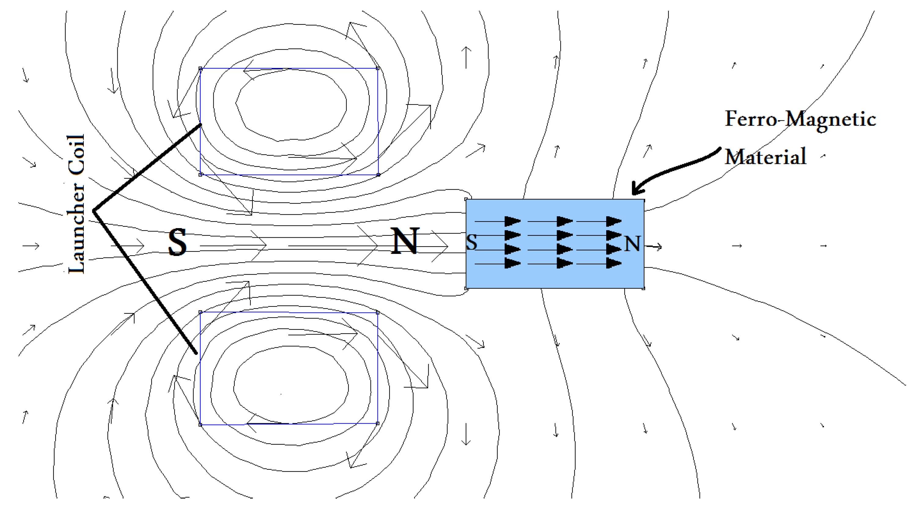
As the magnetic force is highly related to the magnetic circuit reluctance, as shown in [23], we theoretically and experimentally study the effect of decreasing the magnetic circuit reluctance on the projectile velocity by introducing a new design with a soft iron laminated yoke around the coil. The design depends on decreasing the air gap between the two ends of the projectile. This produces higher magnetic flux density and boosts the number of flux lines. This may cause saturation of the iron yoke earlier than usual, therefore high saturation flux density material is used to avoid that. The presence of an iron yoke around the coil makes a huge change in its inductance according to the armature position which results in an enormous force according to Equation (1). This equation shows that the force is directly proportional to the ratio between the change in the inductance to the change in position. And because the change in position is approximately constant, the force increases as the change in inductance increases. Moreover, referring to previous work [24], the coil is wound in a double circuit to reduce copper losses and increase the efficiency compared to the case of using a single wire. In addition, this configuration extends the launcher voltage range.
F x = d d x ( 1 2 L x i L 2 x , t )
Researchers in [25] concluded that the armature (projectile) material should be have high saturation flux density as an essential requirement. They also demonstrated the eddy current problem, which negatively affects the device’s efficiency because it consumes a significant amount of energy. The resistivity of the ejected material is instrumental in reducing the eddy current. Researchers in [25] changed the projectile’s shape and material to drop the projectile conductivity because lower resistance would result in higher eddy currents and more significant Lorentz force. As a result, highly conductive materials will reduce the resultant propulsion force. This problem has been restricted by the laminating method. In this paper, the projectile is solid and made of medium carbon steel material, to preserve the projectile strength while hitting the obstacles. However, the saturation of this material is a problem that led to a poor increase in the projectile velocity at higher voltages. The iron yoke developed in this work is made of laminated soft iron sheets.
The authors of [26] found that improving the discharge circuit of the launcher coil leads to a reduction in the suck-back force. The suck-back force is a reverse force that appears when the projectile crosses the coil’s first half. They used an IGBT switch to control the turning on and turning off time. Suck-back force is the leading cause of magnetic projectile damping when the projectile centerline coincides with the launcher coil centerline. There is a challenge in introducing new discharging circuits. In [24], a previous work of the same authors of this work, the effect of suck-back force was addressed by decreasing the number of magnetic flux lines that pass through the projectile after reaching the second half of the coil by changing the shape of the coil into a conical shape.
The application targeted by this work is micro- and nanosatellite launching. But this kind of launcher is limited in its efficiency which may force an increase in the number of stages to achieve the Earth escape velocity as in the case of the Sandia launcher [4]. A flying launchpad could be used to use the merits of this launcher and decrease the number of stages. The flying launchpad transmits the launcher to the required height to reduce the needed energy to propel the satellite with its available capabilities. The velocity of the launcher introduced in this paper is extendable to any required velocity. But to prove the concept of improving the launcher by adding an iron yoke and verifying security and safety constraints, the speed in all experiments was limited as in this work. Heat generated through the launching process can be estimated by the analysis that was performed in [27].
All mentioned references use higher input voltage or the number of stages to raise the output velocity which requires much energy. In addition, these methods do not contribute to increasing efficiency further. But no one has used the same input voltage and tried to decrease the magnetic reluctance (by adding an iron yoke) and save a huge amount of energy.
The research work in this paper mainly contributes to a new design idea for the launcher. To demonstrate this idea, the main parts of the launcher must be illustrated. This launcher consists of four main parts:
  • Launcher coil: this part generates the needed magnetic flux lines and has many parameters to control the number of these flux lines.
  • Capacitor bank: this component stores a large amount of energy to discharge in the launcher coil to generate a time-changing current.
  • Launching circuit: this circuit controls the current that passes from the capacitor to the launching coil by using a high-current thyristor and its firing circuit.
  • Control circuit: this circuit is responsible for managing the charging time and firing signal to the thyristor and measuring the exit velocity.
The modifications are to add an iron yoke around the launcher coil and carry this launcher on a flying launchpad. This design idea mainly contributes to:
  • Launching a satellite from a flying launchpad may reduce many stresses on the satellite while launching. In addition, less money is required compared to building a massive launchpad on the ground to launch the satellites with the escape velocity of the Earth. Moreover, safety is ensured because the flying launchpad can safely launch satellites from anywhere. Finally, the percentage of success increases with the flying launchpad because it is near the low Earth orbit.
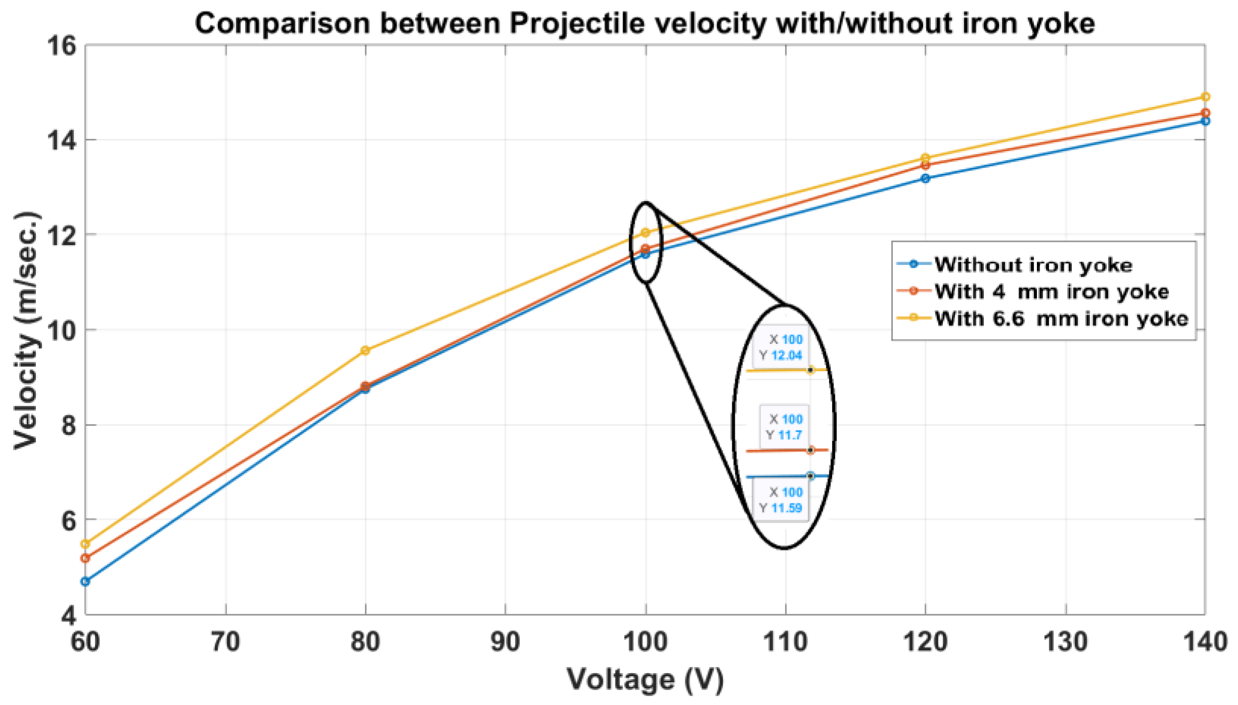
  • Adding an iron yoke significantly increases the number of magnetic flux lines by reducing the magnetic reluctance of the launcher coil which was achieved by adding a laminated iron yoke around the launcher coil instead of increasing the input voltage of the single stage as in [7,12,16,17,26].
  • Magnetic flux lines are strengthened, resulting in an increased number of aligned magnetic dipole moments. The increasing number of aligned magnetic dipole moments results in a higher attractive force.
  • The operating voltage required to achieve a pre-defined velocity is reduced. In other words, the voltage an ordinary launcher uses for the same speed is higher than the voltage a modified launcher needs. This may lead to a reduction of the required rated voltage of launching devices and lower the cost.
  • Adding an iron yoke makes the magnetic path defined. The magnetic path length directly affects the coil inductance. Consequently, the deduction of a mathematical model for the system becomes smoother than before.
There are some limitations that could potentially limit the use of an iron yoke:
  • Increase in the launcher weight.
  • A velocity limitation due to low saturation flux density in the case of poor-permeability ferromagnetic materials.
  • Energy loss due to eddy currents produced in the case of high-conductivity ferromagnetic materials.
The rest of the paper is organized as follows: Section 2 shows the application of the developed launcher. Section 3 describes a detailed explanation of the design of the launcher system modules. Section 4 gives the modified system equations. Section 5 describes the operation algorithm of the launcher. Then, the experimental work is carried out and a discussion of the results is presented by comparing the modified launcher with the system used in the literature [7,16] in Section 6. Future work suggestions are presented in Section 8. Finally, Section 9 concludes this paper.

2. A Microsatellite Launcher Fixed on Top of an Aircraft

Electromagnetic launchers are still in the modification phase and the exit velocity of these launchers does not reach the escape velocity of the Earth. Therefore, a multi-stage electromagnetic launcher is not used alone to launch microsatellites and nanosatellites into low Earth orbit. For instance, in [4], Sandia researchers built a 9000-coil launcher to accelerate a 600 kg armature at 6 km/sec. But this velocity is not enough to reach to low Earth orbit, therefore they added a boost rocket to circularize the orbit of the satellite and complete the journey to low Earth orbit. To gain the advantage of the launcher’s merits, in addition to achieving the goal of propelling satellites to low Earth orbit without adding a boost rocket, an aircraft is used to reduce the distance between the launchpad and the low Earth orbit. The launcher is fixed on top of an aircraft as shown in Figure 1. This solution will allow the launcher to be used with its available capabilities. Launching satellites from high-altitude pads has many advantages. Some of these advantages are that the atmosphere at high altitudes is thinner, which means less friction and energy consumption, and the airplane or the aircraft can move the launchpad anywhere. For instance, NASA used the same technique to launch Orbital ATK’s Pegasus rocket (manufactured by NASA) as in [28]. The Pegasus rocket got eight microsatellites into space. The Pegasus rocket is conventional but air-launched instead of lifting off from the ground. The Pegasus rocket started its trip from a flying launchpad at about 39,000 feet.

3. Description of the Launcher System Modules

The system modules are the launcher coil, power circuit, control circuit, voltage-measuring circuit, and velocity-measuring circuit (speedometer). Each module is described in detail in the following subsections.

3.1. Launcher Coil

This unit is the central part of this system. It is responsible for generating the magnetic field that exerts a magnetic force to accelerate the projectile. The launcher coil consists of several windings of a double-circuited coil wrapped around a hollow dielectric tube. This reduces the overall resistance and extends the coil’s frequency range. To illustrate the idea of this work, a launcher with an iron yoke as shown in Figure 2 and an ordinary launcher without an iron yoke as shown in Figure 2 are manufactured. To demonstrate the effect of the iron yoke’s cross-section area on the performance, two designs of the iron yoke as shown in Figure 3 are manufactured, one with a larger cross-section area than the other. The terminals of the coil are connected to the terminals of a capacitor bank through a power thyristor. The coil parameters are listed in Table 1. The efficiency peaks when the projectile and the launcher’s coil have the same length as examined in [24].

3.2. Power Circuit

The power circuit is the power source for the launcher system. It generates five isolated DC sources to energize the control circuit with all needed supplies and to provide a high-voltage direct current to charge the capacitor bank, as illustrated in Figure 4. The voltage level can be changed by using a multi-output high-frequency transformer. The power circuit is based on the principle of energy exchange between a primary coil of the high-frequency transformer and a capacitor to generate a high-frequency alternating current. This process is controlled by two high-frequency high-current MOSFETs and some diodes. Then, four step-down coils and a step-up coil are wrapped around the same high-frequency transformer core and, finally, these output sources are rectified as listed in Table 2.

3.3. Launching Circuit

This circuit controls the current that passes from the capacitor to the launching coil. The capacitor bank consists of two high-voltage capacitors, each 2500 µF–450 V as shown in Figure 5. The circuit consists of a high-current thyristor, its driving circuit, and the freewheel diode to discharge the launching coil energy after launching.

3.4. Velocity-Measuring Module (Speedometer)

This module is designed to measure the speed of the projectile. Its idea is based on measuring the time between two light interrupters with a known distance (10 mm) as shown in Figure 6 and the processor of the microcontroller uses Equation (2) to calculate the speed after measuring the time between two light interrupters.
v = Δ x Δ t    

3.5. Voltage-Measuring Module

Measuring the capacitor bank voltage and reporting it without direct contact with the microcontroller are a challenge. Therefore, the circuit diagram shown in Figure 7 is modified to measure voltage and convert it to a period. This circuit is very convenient for measuring high DC voltage. It completely isolates the high-voltage and low-voltage sides (control circuits). This module comprises three optoisolators, comparators, capacitors, and voltage regulators. In detail, a calibrated capacitor is charged through a calibrated resistor by the measured voltage. As the estimated voltage increases, the capacitor is charged faster. During the charging process, the voltage across the capacitor is compared with a reference voltage to obtain the time pulse as shown in Figure 7. As demonstrated, this circuit converts any input voltage into a time pulse with a different duration according to the input voltage’s level.

3.6. Control Panel

The control circuit is designed to set, control, and monitor the voltage of the capacitor, handle the firing process, and measure the projectile’s exit velocity at the barrel’s end. This board consists of a microcontroller (PIC16f877A) that imported from China, LCD 16 × 2 screen, IGBT switch, and some connectors as shown in Figure 8. The microcontroller receives and transmits the signal from and to other modules to handle all the functions required. The IGBT switch is an electronic switch used to control the charging cycle time through the microcontroller. This microcontroller is coded with Mikroc Pro for PIC.
The experimental setup includes the modified launcher, power circuit board, velocity-measuring module, and capacitor bank which are illustrated in Figure 9.

4. Theory of the Launcher System Design

4.1. Launcher Coil Modeling

The proposed launcher system is designed with a coil (inductor and resistor), capacitor, and power thyristor (2 N1599), as shown in Figure 10. Therefore, it can be simplified to an RLC circuit of the internal resistor R = 0.125   Ω . A flyback diode (D2) is connected in parallel to protect the switch from the backward current of the launcher coil. Resistor R1 of 0.07 Ω is used in series with the launcher coil to help measure the current. Kirchhoff’s voltage law (KVL) for the circuit while switching on can be written as in Equations (3) and (4). In this circuit, the inductance varies with the projectile’s position ( x ) and the position is a function of time, therefore the inductance is a function of time as well. In addition, launching the capacitor is the source of this circuit, therefore it is modeled as a DC battery and all component voltages are subtracted from it. The current waveform is divided into two parts. The first part follows the waveform of Equation (4), while the second part is a freewheel process through the shunt diode. The current starts to flow through the diode when the coil voltage equals the capacitor voltage.
V C = V R + V R 1 + V L
V C o 1 C i   d t = R   i L t + R 1   i L t + L x   d i L t d t + i L t d L x d t

4.2. Calculation of the Magnetic Force and Magnetic Circuit Reluctance

The mathematical equation for magnetic circuit reluctance is difficult to deduce because of the fringing effect that might make the area of the air gap difficult to estimate. Accordingly, adding an iron yoke around the launcher coil might be essential to attract most of the flux lines to a known area medium. In addition, this makes the magnetic flux path through the iron yoke defined. As displayed in Figure 11, the launcher coil generates magnetomotive force, letting the magnetic lines pass through two paths. The first path is the surrounding air and the second is through the iron yoke. Equation (5) is used to calculate each path’s reluctance. Equation (6) illustrates the resultant reluctance of the launcher coil. Then, the inductance of the launcher coil can be calculated through Equation (7). It is noticed that adding the iron yoke increases the inductance values compared to the ordinary launcher which leads to a higher derivative of the launcher coil inductance with respect to the projectile position ( d L x d x ) because the coil inductance is inversely proportional to the magnetic reluctance as in Equation (7). The force, as shown in Equations (1) and (8), is in direct proportion to the derivative of the launcher coil inductance with respect to the projectile position. There is a viscous friction force due to the air resistance inside the launcher barrel with a coefficient of b as shown in Equation (9). The air resistance coefficient depends on many factors such as the face area of the projectile, however, this value is initialized and will differ when experimentally determined. The projectile’s motion is rectilinear so Equation (10) is used to evaluate the velocity equation. Equation (8) is divided by the projectile mass to obtain the acceleration equation of the projectile, as displayed in Equation (10).
= l μ r μ o A
where:
R = reluctance of magnetic circuit around the coil.
l = length of the magnetic path.
A = effective cross-section area of the coil.
μ o = permeability of air.
μ r = relative permeability of the material.
t o t a l x = p r o j e c t i l e + 1 1 2 a i r g a p + v a r i a b l e   a i r g a p x + y o k e + 1 s u r r o u n d i n g   a i r
L x = N 2 total x = N 2 projectile + 1 1 2 a i r g a p + v a r i a b l e   a i r g a p x + y o k e + 1 s u r r o u n d i n g   a i r
where:
N = number of turns of the coil.
F x = x M a g n e t i c   E n e r g y = x 0 t v = 0 V L i L   d t = x 0 t v = 0 L x d   i L x , t d t   i L x , t d t = 1 2 i 2 d L x d x
F x = m a x + b   v x
a x = F x b   v x m = v x d v x d x
where:
a x = projectile acceleration.
v x = projectile velocity.
m = projectile mass.

5. Description of the Operation Algorithm of the Launcher

The proposed system has been constructed from different blocks (modules), as shown in Figure 12. These modules are explained in detail in Section 3. Figure 13 shows a flowchart describing the process flow for the entire launcher system. First, the capacitor is charged through a high-voltage DC charging circuit. Second, a control panel controls the charging process. The control panel manages the voltage set point and the firing process and measures the projectile’s velocity. In the firing process, current pulses travel through the solenoid winding via a high-current-controlled thyristor (SCR). A PIC16F877A microcontroller is utilized to handle all the control panel tasks. The magnetic dipoles inside the ferromagnetic projectile begin to orient and arrange in the direction of the magnetic flux lines, which makes the projectile inside this tube move due to the presence of an attractive force between the coil and the ferromagnetic dipoles and this is the reason for the existence of magnetic force as proven in [13,18]; this has been verified experimentally in this work in Section 6.1. Finally, the speedometer panel enables the microcontroller to measure the speed.

6. Experimental Work

6.1. Verification of the Magnetic Dipoles Model

In this work, several experiments have been conducted to prove that the projectile is composed of a massive number of magnetic dipoles and to verify the theory in [13,18] experimentally. Three different materials (iron (medium carbon), copper, and aluminum) are examined as examples of ferromagnetic and paramagnetic materials. The conditions for the experiment are mentioned in Table 3. The velocity of each projectile is measured and listed in Table 4.

6.2. Examination of the New Design Performance

In this experiment, three launcher configurations are examined. The first configuration is the same launcher type used by the authors of [7,16,22,24,25,26]. The second and third configurations are soft iron laminated yoke launchers. Two different-width yokes have been examined, one is 4 mm wide and the second is 6.6 mm wide as shown in Figure 3. Table 5 shows the settings for experiment parameters. The experiment results are listed in Table 6 and the efficiencies are calculated using Equation (11).
η = E k . E E l e . = 1 2 m   v 2 1 2 C   V C o 2

7. Discussion of the Results

7.1. Verification of the Magnetic Dipole Model

This experiment falsifies the claim in [8,19,20] about thinking beyond projectile propulsion. It is claimed that the mutual induction between the launcher coil and the slug (as a single-turn coil) is the cause of the motion because it induced an opposite current in the projectile, producing an opposite pole that caused an attraction force. In that case, copper and aluminum should be the ideal materials for propulsion because they have a lower resistivity in comparison with iron. But copper and aluminum projectiles move just a few millimeters without reaching the velocity measuring point. This experiment has shown that magnetic dipoles allow the magnetic field to exert an attractive force on the ferromagnetic material as proved theoretically in [13,18]. FEMM 4.2 software was used to plot Figure 14 to show that domains in ferromagnetic material become magnetized in the direction of the external magnetic field. This magnetization will produce an opposite magnetic pole in the ferromagnetic material to the pole which is nearest to it. Therefore, the developed opposite pole will be attracted to the magnetic field. But mutual induction between the launcher coil and the slug causes energy loss through the projectile’s electrical resistance even in the ferromagnetic material.

7.2. Examination of the New Design Performance

The soft iron laminated yoke launcher is an innovative design that reduces the magnetic circuit reluctance by shortening the air gap path for the lines of magnetic flux through the iron yoke. And due to the low reluctance of the iron yoke, the overall reluctance drops as mentioned in Equation (5). Consequently, the inductance of the coil is significantly changed between the initial and plugged positions of the projectile which develops higher force than usual as in Equation (1). Two launchers of the same dimensions are built. These two launchers are identical, but one has an iron yoke and the other does not. A comparison has been carried out between them as they have the same design aspects for a controlled experiment, and this illustrates the superiority of adding an iron yoke. According to the experimental results shown in Table 6 and Figure 15, a significant improvement in the velocity of the projectile reaches 17% compared to the launcher without an iron yoke. Moreover, the efficiency in Table 6 is calculated using Equation (11) in the case of with/without iron yoke to highlight the improvement that rises by 36% over the ordinary launcher’s efficiency. In addition, it is proven through Figure 15 and Figure 16 that higher velocities can be achieved by the same voltages by adding an iron yoke. To check the device’s eligibility for voltage increase, the ratio between the change in velocity and the voltage change was calculated, as shown in Table 7, and is plotted in Figure 16 in the case of a 6.6 mm iron yoke. This table shows that at high voltages the ratio drops due to the suck-back effect, the saturation of the projectile, and the eddy current effect. when a massive number of magnetic flux lines flow inside the ferromagnetic slug.
To investigate the influence of the iron yoke on the magnetic flux lines, FEMM 4.2 software was used to plot the magnetic flux lines of the launcher coil in the presence and absence of the iron yoke as shown in Figure 17. Figure 17 shows four cases for the launcher, two of them when the projectile is at the start with/without an iron yoke while the other two are when the projectile is plugged into the launcher with/without an iron yoke. To achieve fair judgment, the four cases are simulated at the same time and, consequently, the legend is valid for all of them. Figure 17b,d show the distribution of the magnetic flux lines in the case of the iron yoke where the magnetic flux density is approximately three times higher than in the case of the absence of the iron yoke as is the case in Figure 17a,c. In general, Figure 18 shows the superiority of the proposed design as it boosts the magnetic flux line number without consuming excess energy.
There are many design aspects considered in this work. To compare between the different design aspects of launchers, the efficiency must be calculated for each. The superiority of the proposed design compared to three different recent research works [7,16,22] is illustrated in Table 8. The efficiency increased by more than two times compared to [16], more than 18 times compared to [7], and about 136% compared to [22] as illustrated in Figure 18. A comparison with more references is carried out to illustrate the effect of combining many design aspects in one launcher including the following:
  • Use a double twisted wire coil instead of a single wire coil.
  • The projectile length set to the same value as the launcher coil length.
  • A longitudinal laminated iron yoke added around the launcher coil with an area at least the same as the projectile cross-section area.

8. Future Work

As shown in this paper, the iron yoke increases the efficiency of the launcher. However, at higher voltages, the efficiency drops for many reasons. The main reason is the suck-back force. This force is generated when the current still flows in the coil and the projectile enters the second half of the coil. The next challenge is the hysteresis force generated from the current induced in the projectile due to Faraday’s law. Therefore, the future work ideas are summarized as follows:
  • The authors of [25] deciphered the projectile material and shape issues. They found that a projectile made of radially laminated silicon steel sheets reduces the eddy current induced in the projectile. Therefore, this enhancement may give better efficiency if mixed with the proposed iron yoke launcher.
  • The authors of [26] reduced the suck-back force by improving the discharge circuit of the launcher coil. Therefore, the combination of the modified iron yoke launcher and the improved discharge circuit deserves to be investigated.
  • The authors of [24] reduced the suck-back force by using a conical-shapedcoil instead of the ordinary straight coil. Therefore, the design of a conical-shaped coil with an iron yoke is recommended to be examined.

9. Conclusions

This study investigated the magnetic forces produced in an electromagnetic launcher and the impact of an iron yoke on its performance. Results from experimental testing confirm that magnetic dipole moments are the primary source of magnetic force, and the installation of an iron yoke improves the launcher’s performance by reducing magnetic reluctance during propulsion. Suck-back force is a force developed when the current continues to pass while the projectile passes the second half of the launcher. Consequently, the study also found that the efficiency decreases at higher operating voltages due to an increase in the suck-back force, which is further amplified by adding the iron yoke. Thus, to fully benefit from the installation of an iron yoke, the suck-back force should be reduced. Overall, this research provides valuable insights into designing effective electromagnetic launchers and serves as a reference for future studies in this area.

Author Contributions

Conceptualization, M.M.M.A., S.M.A. and H.E.-H.; methodology, M.M.M.A.; software, M.M.M.A.; validation, M.M.M.A., S.M.A. and H.E.-H.; formal analysis, M.M.M.A., S.M.A. and H.E.-H.; investigation, M.M.M.A.; resources, M.M.M.A.; data curation, M.M.M.A.; writing—original draft preparation, M.M.M.A.; writing—review and editing, M.M.M.A., S.M.A. and H.E.-H.; visualization, M.M.M.A., S.M.A. and H.E.-H.; supervision, S.M.A., H.E.-H. and T.M.; project administration, S.M.A. and H.E.-H.; funding acquisition, M.M.M.A. All authors have read and agreed to the published version of the manuscript.

Funding

This research received no external funding.

Data Availability Statement

Data is unavailable due to privacy or ethical restrictions.

Conflicts of Interest

The authors declare no conflict of interest.

Nomenclature

L x Coil self-inductance (H)
R Coil internal resistance (0.125 Ω)
R 1 External measuring resistance (0.07 Ω)
C Capacitor bank capacitance (F)
V C o The initial voltage of the capacitor bank (v)
R The reluctance of the magnetic circuit around the coil
l Length of the magnetic path
A The effective cross-section area of the coil
μ o Permeability of air
μ r Relative permeability of the material
N Number of turns of the coil
a x Projectile acceleration
v x Projectile velocity
m Projectile mass
bViscous coefficient
E k . The kinetic energy of the projectile (J)
E E l e . Electrical energy stored in the capacitor bank
v Muzzle velocity

References

  1. Hasirci, U.; Balikci, A. Design of an Electromagnetic Launcher for Earth-to-Orbit (ETO) microsatellite systems. In Proceedings of the 2009 4th International Conference on Recent Advances in Space Technologies, Istanbul, Turkey, 11–13 June 2009; pp. 233–236. [Google Scholar] [CrossRef]
  2. Lipinski, R.J. An electromagnetic induction launcher for Navy applications. Present. Hypervelocity Weapons Nav. Appl. Crit. Rev. Induction Launcher Technol. Meet. Albuquerque 1991, 26–27. [Google Scholar]
  3. Kaye, R.J.; Turman, B.N.; Shope, S.L. Applications of coilgun electromagnetic propulsion technology. In Proceedings of the Conference Record of the Twenty-Fifth International Power Modulator Symposium, 2002 and 2002 High-Voltage Workshop, Hollywood, CA, USA, 30 June–3 July 2002; pp. 703–707. [Google Scholar] [CrossRef]
  4. Lipinski, R.J.; Beard, S.; Boyes, J.; Cnare, E.C.; Cowan, M.; Duggin, B.W.; Kaye, R.J.; Morgan, R.M.; Outka, D.; Potter, D.; et al. Space applications for contactless coilguns. IEEE Trans. Magn. 1993, 29, 691–695. [Google Scholar] [CrossRef]
  5. Kaye, R.J.; Shokair, I.R.; Wavrik, R.W.; Dempsey, J.F.; Honey, W.E.; Shimp, K.J.; Douglas, G.M. Design and Evaluation of Coils for a 50 mm Diameter Induction Coilgun Launcher. IEEE Trans. Magn. 1995, 31, 478–483. [Google Scholar] [CrossRef]
  6. Schroeder, J.M.; Gully, J.H.; Driga, M.D. Electromagnetic launchers for space applications. IEEE Trans. Magn. 1989, 25, 504–507. [Google Scholar] [CrossRef]
  7. Orbach, Y.; Oren, M.; Golan, A.; Einat, M. Reluctance Launcher Coil-Gun Simulations and Experiment. IEEE Trans. Plasma Sci. 2019, 47, 1358–1363. [Google Scholar] [CrossRef]
  8. Kaye, R.J. Operational requirements and issues for coilgun electromagnetic launchers. IEEE Trans. Magn. 2005, 41, 194–199. [Google Scholar] [CrossRef]
  9. Mohamed, H.M.; Abdalla, M.A.; Mitkees, A.; Sabery, W. Overlapped Electromagnetic Coilgun for Low Speed Projectiles. J. Magn. 2015, 20, 322–329. [Google Scholar] [CrossRef]
  10. Abdo, T.M.; Elrefai, A.L.; Adly, A.A.; Mahgoub, O.A. Performance analysis of coil-gun electromagnetic launcher using a finite element coupled model. In Proceedings of the 2016 Eighteenth International Middle East Power Systems Conference (MEPCON), Cairo, Egypt, 27–29 December 2016; pp. 506–511. [Google Scholar] [CrossRef]
  11. Winarno, B.; Putra, R.G.; Yuwono, I.; Gunawan, A.I.; Sumantri, B. Control of Velocity Projectile on Multistage Coil gun. In Proceedings of the 2018 International Conference on Applied Science and Technology (iCAST), Manado, Indonesia, 26–27 October 2018; pp. 24–29. [Google Scholar] [CrossRef]
  12. Coramik, M.; Citak, H.; Bicakci, S.; Gunes, H.; Aydin, Y.; Ege, Y. Studies to Increase Barrel Exit Velocity for Four-Stage Coil-Gun. IEEE Trans. Plasma Sci. 2020, 48, 2618–2627. [Google Scholar] [CrossRef]
  13. Barandes, J.A. Can Magnetic Forces Do Work? arXiv 2019, arXiv:1911.08890. [Google Scholar]
  14. Wright, M.R.; Kuznetsov, S.B.; Kloesel, K.J. A lunar electromagnetic launch system for in situ resource utilization. IEEE Trans. Plasma Sci. 2011, 39, 521–528. [Google Scholar] [CrossRef]
  15. Mascolo, L.; Stoica, A. Electro-Magnetic Launchers on the Moon: A Feasibility Study. In Proceedings of the 2018 NASA/ESA Conference on Adaptive Hardware and Systems (AHS), Edinburgh, UK, 6–9 August 2018; pp. 37–42. [Google Scholar] [CrossRef]
  16. Einat, M.; Orbach, Y. A multi-stage 130 m/s reluctance linear electromagnetic launcher. Sci. Rep. 2023, 13, 218. [Google Scholar] [CrossRef] [PubMed]
  17. Cos, I. Optimization of parameters acting on a projectile velocity within a four stage induction coil-gun. Measurement 2010, 43, 1656–1660. [Google Scholar] [CrossRef]
  18. Barandes, J.A. On Magnetic Forces and Work. Found. Phys. 2021, 51, 79. [Google Scholar] [CrossRef]
  19. Liu, S.; Ruan, J.; Huang, D.; Wan, Z. Analysis of Inductive Coil Gun Performance Based on Field Coupling Circuit Method. In Proceedings of the 2009 IEEE 6th International Power Electronics and Motion Control Conference, Wuhan, China, 17–20 May 2009; Volume 3, pp. 845–849. [Google Scholar]
  20. Yadong, Z.; Ying, W.; Jiangjun, R. Capacitor-driven coil-gun scaling relationships. IEEE Trans. Plasma Sci. 2011, 39, 220–224. [Google Scholar] [CrossRef]
  21. Lee, S.J.; Kim, J.H.; Kim, S.H. Design and experiments of multi-stage coil gun system. J. Vibroengineering 2016, 18, 2053–2060. [Google Scholar] [CrossRef]
  22. Daldaban, F.; Sari, V. Design and implementation of a three-coil linear reluctance launcher. In Proceedings of the 2014 16th International Power Electronics and Motion Control Conference and Exposition, Antalya, Turkey, 21–24 September 2014; pp. 1084–1088. [Google Scholar] [CrossRef]
  23. Naseradinmousavi, P.; Nataraj, C. Nonlinear mathematical modeling of butterfly valves driven by solenoid actuators. Appl. Math. Model. 2011, 35, 2324–2335. [Google Scholar] [CrossRef]
  24. Abdo, M.M.; Fanni, M.; Miyashita, T.; Ahmed, S.M. The Effect of Coil Geometry and Winding Method on the Electromagnetic Launcher Performance. In Proceedings of the IECON 2022—48th Annual Conference of the IEEE Industrial Electronics Society, Brussels, Belgium, 17–20 October 2022; pp. 1–5. [Google Scholar]
  25. Deng, H.; Wang, Y.; Yan, Z.M. Study on the influence of armature on the efficiency of reluctance accelerator. Def. Technol. 2021, 18. [Google Scholar] [CrossRef]
  26. Deng, H.; Wang, Y.; Lu, F.; Yan, Z. Optimization of reluctance accelerator efficiency by an improved discharging circuit. Def. Technol. 2020, 16, 662–667. [Google Scholar] [CrossRef]
  27. Zandi, S.; Seresht, M.J.; Khan, A.; Gorji, N.E. Simulation of heat loss in Cu2ZnSn4SxSe4−x thin film solar cells: A coupled optical-electrical-thermal modeling. Renew. Energy 2022, 181, 320–328. [Google Scholar] [CrossRef]
  28. Available online: https://www.nasa.gov/feature/cygnss-microsatellites-prepared-for-air-launch-aboard-pegasus-xl-rocket (accessed on 7 August 2017).
Figure 1. Illustration of the launcher on the flying launchpad.
Asi 06 00081 g001
Figure 2. Launcher coil with an iron yoke.
Asi 06 00081 g002
Figure 3. Yoke shape (side and top views).
Asi 06 00081 g003
Figure 4. Power supply board.
Asi 06 00081 g004
Figure 5. Capacitor bank of 5000 μF with a power thyristor.
Asi 06 00081 g005
Figure 6. The velocity measurement module.
Asi 06 00081 g006
Figure 7. Circuit diagram of the voltage-measuring board.
Asi 06 00081 g007
Figure 8. Control circuit board.
Asi 06 00081 g008
Figure 9. The entire electromagnetic launcher system.
Asi 06 00081 g009
Figure 10. The circuit diagram of the launcher.
Asi 06 00081 g010
Figure 11. Equivalent Magnetics circuit of the launcher.
Asi 06 00081 g011
Figure 12. Block diagram of the launcher system.
Asi 06 00081 g012
Figure 13. Flowchart of the entire launcher system.
Asi 06 00081 g013
Figure 14. Magnetic dipole domain direction before and after exposure to launcher magnetic field.
Asi 06 00081 g014
Figure 15. Comparison between the projectile velocities with/without iron yoke.
Asi 06 00081 g015
Figure 16. Comparison between velocity difference percentage for each reading.
Asi 06 00081 g016
Figure 17. Path of Magnetic flux lines with/without iron yoke; (b,d) the projectile is connected. Meanwhile, in (a,c) the projectile starts at the beginning.
Asi 06 00081 g017
Figure 18. Comparison between launcher efficiency of this work and references [7,16,22].
Asi 06 00081 g018
Table 1. Coil Parameters.
Coil ParametersValues
Coil length20 mm
Number of turns100 turns
Inner diameter15 mm
Wire diameter2 × 0.8 mm
Resistance of the coil0.125 Ω
Table 2. The Output Voltages of the Charging Circuit.
Input Voltage12 VDC
Output voltages350 VDC
5 VDC
12 VDC
12 VDC
6 VDC
Capacitor bank5000 μF/450 VDC
Table 3. Conditions for Validation of Magnetic Dipoles.
Temp.VoltageCapacitorCoil LengthProjectile Length
20 C100 V5 mF20 mm20 mm
Table 4. The Projectile Velocity for Different Materials.
Projectile MaterialVelocity (m/s)
Iron (medium carbon)11.59
CopperNear zero
AluminumNear zero
Table 5. Experiment Parameters Settings.
Temp.CapacitorCoil LengthProjectile MassProjectile Length
20 °C5 mF20 mm12.3 gm20 mm
Table 6. Projectile Velocity with/without Iron Yoke.
Cap. VoltageVelocity (m/s) Efficiency   η   % η   Rises   by   %
without Iron
Yoke
4 mm Iron Yoke6.6 mm Iron Yokewithout
Iron Yoke
6.6 mm Iron Yoke
60 v4.75.195.491.5092.0636.5
80 v8.758.819.562.9423.51219.37
100 v11.5911.712.043.33.5668
120 v13.1813.4613.612.9673.1646.63
140 v14.3914.5614.92.62.786.92
Table 7. Ratio Between the Change in Velocity and the Change in Supply Voltage.
Capacitor Voltage Velocity   ( m   s ) Δ v Δ V   m v o l t   ·   s
60 v4.7-
80 v8.750.2025
100 v11.590.142
120 v13.180.0795
140 v14.390.0605
Table 8. A comparison between the efficiency of the launcher of this work with two different references.
Ref. No.Number of StagesUsed Voltage
(Volt)
Vel .   ( m   s e c ) Eff. (%)Year
[16]79001301.322023
[7]11100500.152019
[22]325015.662.042014
This work114014.92.782023
Disclaimer/Publisher’s Note: The statements, opinions and data contained in all publications are solely those of the individual author(s) and contributor(s) and not of MDPI and/or the editor(s). MDPI and/or the editor(s) disclaim responsibility for any injury to people or property resulting from any ideas, methods, instructions or products referred to in the content.

