Review

Pulsed Discharge Plasma in High-Pressure Environment for Water Pollutant Degradation and Nanoparticle Synthesis

1
Department of Materials Process Engineering, Nagoya University, Nagoya 464-8603, Japan
2
Department of Chemical Engineering, Institut Teknologi Sepuluh Nopember, Surabaya 60111, Indonesia
3
School of Chemistry & Chemical Engineering, Shanghai Jiao Tong University, Shanghai 200240, China
*
Author to whom correspondence should be addressed.
Plasma 2021, 4(2), 309-331; https://doi.org/10.3390/plasma4020021
Submission received: 12 April 2021 / Revised: 11 May 2021 / Accepted: 31 May 2021 / Published: 4 June 2021
(This article belongs to the Special Issue Feature Papers in Plasma Sciences)

Abstract

:
The application of high-voltage discharge plasma for water pollutant decomposition and the synthesis of nanoparticles under a high-pressure argon gas environment (~4 MPa) was demonstrated. The experiments were carried out in a batch-type system at room temperature with a pulsed DC power supply (15.4 to 18.6 kV) as a discharge plasma source. The results showed that the electrode materials, the pulsed repetition rates, the applied number of pulses, and the applied voltages had a significant effect on the degradation reactions of organic compounds. Furthermore, carbon solid materials from glycine decomposition were generated during the high-voltage discharge plasma treatment under high-pressure conditions, while Raman spectra and the HRTEM images indicated that titanium dioxide with a brookite structure and titanium carbide nanoparticles were also formed under these conditions. It was concluded that this process is applicable in practice and may lead to advanced organic compound decomposition and metal-based nanoparticle synthesis technologies.

1. Introduction

Plasma is frequently assigned as the fourth state of matter, with the others being gas, liquid, and solid. It consists of negative ions or electrons, positive ions, and neutral particles; hence, in the universe, plasma is the most plentiful form of ordinary matter. In principle, plasma can be formed by supplying energy to a neutral gas, leading to charge carrier formation, where various ways have been applied to neutral gas to provide the required energy for the generation of plasma, i.e., exothermic chemical reaction, gas adiabatic compression, and an energetic beam [1,2,3,4,5].
When an electric discharge is employed to form a plasma in a gas-liquid environment, at least one of the electrodes should be in contact with the liquid phase. The discharge plasma is initiated when the electric field is sufficient to supply more energy to electrons, and eventually, it may induce the breakdown of the gas. Consequently, the discharge plasma is usually produced in the gas phase where the electrical breakdown takes place. Thereafter, this discharge plasma interacts with the liquid medium. When the liquid water acts as a liquid medium for the generation of discharge plasma in the gas-liquid environment, the high reactivity of molecules or radicals might be produced, i.e., hydrogen molecules, oxygen molecules, hydrogen peroxide molecules, and hydroxyl radicals. Hence, discharge plasma in a gas-liquid water environment is considered one of the most promising technologies that can be applied in various fields, i.e., water pollutant removal, biological inactivation, polymer surface modification, chemical synthesis, and nanoparticle synthesis [6,7,8,9,10]. In addition to the chemical effects, the discharge plasma in the gas-liquid water environment also results in physical effects, i.e., ultraviolet radiation and shockwave generation [6,7,11,12,13,14,15,16,17]. Another advantage regarding the use of discharge plasma in the gas-liquid water environment is that the discharge plasma is usually more easily formed in the gas phase than in the liquid state. Hence, less energy is involved to form a plasma in a gas-liquid water system than is involved to form plasma that is applied directly in a liquid water state [8,9]. Furthermore, the operating cost during applying the discharge plasma in the gas-liquid water environments can be minimized.
Here, high-voltage discharge plasma in gas-liquid water environments under atmospheric and high-pressure argon was employed as media for water pollutant removal and nanoparticle synthesis in a batch-type system. Argon was selected as the gas phase due to it being an inert and non-polluting gas and possessing a low breakdown voltage. It is one of the most observed and used chemical elements, and this gas is the gas most often employed in plasma generation processes due to the excellent stability of the electrical discharge. Applying a high-voltage discharge plasma under an argon environment might also provide an intense source of ultraviolet (UV) radiation. Argon has a low critical point (Tc = 150.9 K, Pc = 4.9 MPa) and it seems to possess superior optical transparency due to argon being monatomic [6,7,9,18,19,20,21,22]. Takamatsu et al. observed reactive species generation in a nonequilibrium atmospheric pressure plasma system using various gas species, including argon and helium. The argon gas was relatively convenient to produce plasma compared to helium gas; furthermore, the highest amounts of reactive species especially hydroxyl and hydrogen radicals were obtained when the argon gas was used in the gas phase [19]. Similar results were also reported by Mohades et al. when they investigated reactive species production in a thin film of water using a dielectric barrier discharge with nitrogen, oxygen, air, helium, or argon as the gas phase [21]. Jaiswal and Aguirre deduced that argon gas with an improved atomic oxygen level can be employed as an efficient and cheaper technique for wastewater treatment due to the high energy efficiency and the faster decomposition of the methylene blue dye as a water pollutant after they conducted experiments to decompose methylene blue dye using an atmospheric pressure plasma jet system with argon and helium as the gas phases [22]. It is well known that low-pressure plasma is applied for various applications. However, to create low-pressure conditions, a vacuum system is required, resulting in the operating system being complex and costly. Hence, applying a high-voltage discharge plasma under atmospheric and high-pressure conditions with argon as the gas phase may eliminate the demerits of the low-pressure condition [23,24,25,26,27]. However, new challenges arise due to the high voltage requirement for gas breakdown and the difficulty in sustaining discharge plasma under atmospheric and high-pressure conditions. As a water pollutant model compound, methyl orange dye was dissolved in distilled water. This dye compound is a kind of azo dye that possesses a large number of aromatic rings in its molecular structure. Methyl orange possesses an intense color and is used in some industries for instant printing and textiles [28,29,30]. Various dye wastewater treatment processes, i.e., biological, physical, and chemical treatments, were applied to remove this dye color [9,16,22,31,32,33]. However, these treatment processes are not always suitable options owing to the low efficiency, the high operating cost, and the possibility of secondary pollutant generation. For instance, it is difficult to decompose biologically toxic, recalcitrant, and inhibitory pollutants using a biological treatment. In physical and chemical treatments, the treatment process is generally very costly and may produce a secondary pollutant. Hence, an efficient, cost-effective, and advanced treatment process is needed for dye removal from wastewater. Onga et al. performed experiments for textile dye removal from wastewater using pulsed corona discharges with 1-amino-4-[3-(4,6-dichlorotriazin-2-ylamino)-4-sulfophenylamino] anthraquinone-2-sulfonic acid (RB4) and remazol brilliant blue R, 2-(3-(4-amino-9,10-dihydro-3-sulpho-9,90-dioxoanthracen-4-yl)aminobenzenesulphonyl)vinyl)disodiumsulphate (RB19) as azo dye compounds [31]. They reported that the RB4 and RB19 removal efficiency could approach 90% when the pulsed corona discharges were operated at 200 pulses per second (pps) with 132–133 g kW−1 h−1 of applied energy. Barrera et al. also conducted experiments investigating azo dye carmoisine removal using an electro-oxidation plasma process with an aqueous solution as a medium [32]. They reported that by using this electrochemical advanced oxidation process, the decomposition efficiency of the azo dye carmoisine was 100% with a 60 min reaction time. In the case of nanoparticle generation, electrode erosion could be utilized as a source of material for nanoparticle production [8,34,35,36]. Saito et al. successfully produced nickel nanoparticles in a solution-plasma system under stable power supply conditions [34]. Under glow discharge plasma conditions, they reported that the nickel rod electrode surface partially melted, resulting in a spherical nickel nanoparticle in the aqueous solution medium. Jiang et al. also reported that silver nanoparticles could be produced from a silver rod electrode using a spark discharge and a dielectric barrier discharge system [35]. Thus, the electrode degradation phenomenon shifts from an unfavorable process to the desired process.

2. Materials and Methods

2.1. Materials

Glycine (C2H5NO2; product no. 077-00735), lysine (C6H14N2O2; product no. 123-01461), alanine (C3H7NO2; product no. 011-01055), methyl orange (C14H14N3NaO3S; product no. 131-02862), 2,5-dihydroxybenzoic acid (DHB, C7H6O4; product no. 046-02262), and distilled water (H2O; product no. 049-16787) were bought from FUJIFILM Wako Pure Chemical Industries, Ltd., Osaka, Japan. Threonine (C4H9NO3; product no. 33820-82) and ornithine (C5H12N2O2·HCl; product no. 25718-92) were received from Nacalai Tesque Ltd., Kyoto, Japan. Pyrrole (C4H5N; product no. 131709-25ML) was bought from Sigma-Aldrich, Saint Louis, MI, USA. All chemicals had purities exceeding 98.0% and were used without further purification.

2.2. Sample Preparation

To prepare the synthetic dye wastewater, the methyl orange powder was dissolved in distilled water with a concentration of 1000 mg/L. For the pyrrole polymerization experiments, the pyrrole compound was dissolved in distilled water at a 0.1 mol/L concentration as a starting material. As a medium for titanium dioxide nanoparticle synthesis experiments, the glycine powder was dissolved in distilled water with a concentration of 100 g/L. Similar to the glycine solution preparation, the lysine, threonine, alanine, and ornithine were also dissolved in distilled water with a concentration of 50 g/L when they were employed as media for the synthesis of carbon nanoparticles. All solutions were placed in a bottle with a screw cap and agitated (Rexim, RSH-1DR, AS ONE, Osaka, Japan) for approximately 30 min. The bottles were covered by using aluminum foil to avoid light exposure. The preparation was performed at room temperature, and it was then stored in a desiccator at room temperature.

2.3. Experimental Procedure

Figure 1 shows the apparatus scheme for the high-voltage discharge plasma in a gas-liquid environment in a batch-type system. The main apparatus was the batch reactor (SUS-316, AKICO, Tokyo, Japan) with a volume of 15 mL and a pulsed DC power supply (MPC; Suematsu Electronics MPC2000S, Kumamoto, Japan) to generate an electrical discharge plasma. The experimental procedure was presented elsewhere [37,38,39,40,41,42,43]. To start the experiment, the SUS reactor was manually filled with around 5 to 7 mL of the starting material. It was then purged of air by repeatedly using argon gas (three times). A K-type thermocouple and needle valves were employed to monitor and adjust the reactor temperature and the reactor pressure (~4 MPa), respectively. The distance between the metal rod electrode and the aqueous surface medium was set to around 3 mm. After the desired conditions were achieved, the DC pulsed power supply (15.4 to 18.6 kV) was introduced to the SUS reactor through the metal rod electrode to generate the discharge plasma. By using the high-voltage probe and the current transformer, the breakdown voltage and the current were observed by using a digital oscilloscope. The output voltage, pulse duration, and pulse repetition rate could be controlled during the experiment. After the reaction time had elapsed, the apparatus power button was turned off and the needle valve was opened to release the pressure. Next, the SUS reactor was opened and the solution products were collected and analyzed using a UV-Vis spectrophotometer (UV-Vis V550, JASCO Co., Tokyo, Japan) and matrix-assisted laser desorption/ionization time of flight mass spectroscopy (MALDI-TOF-MS; Bruker Tektronix TDS 504D GmbH Reflex III, Wiesbaden, Germany). The nanoparticle products were characterized using transmission electron microscopy (TEM) (JEM-2100Plus, Japan Electronic Co., Ltd., Tokyo, Japan) with energy-dispersive X-ray spectroscopy (EDS) (JEOL, JED-2300T & Gatan, GIF Quantum ER, Japan Electronic Co., Ltd., Tokyo, Japan) and Raman spectroscopy (NRS-1000, Jasco Corporation, Tokyo, Japan). Note, prior to the analysis, the solution product from the amino acids as starting materials was dialyzed using a dialysis membrane (Spectra/Por3, Spectrum Laboratories Inc., Los Angeles, CA, USA) to separate the unreacted amino acids.

3. Results and Discussion

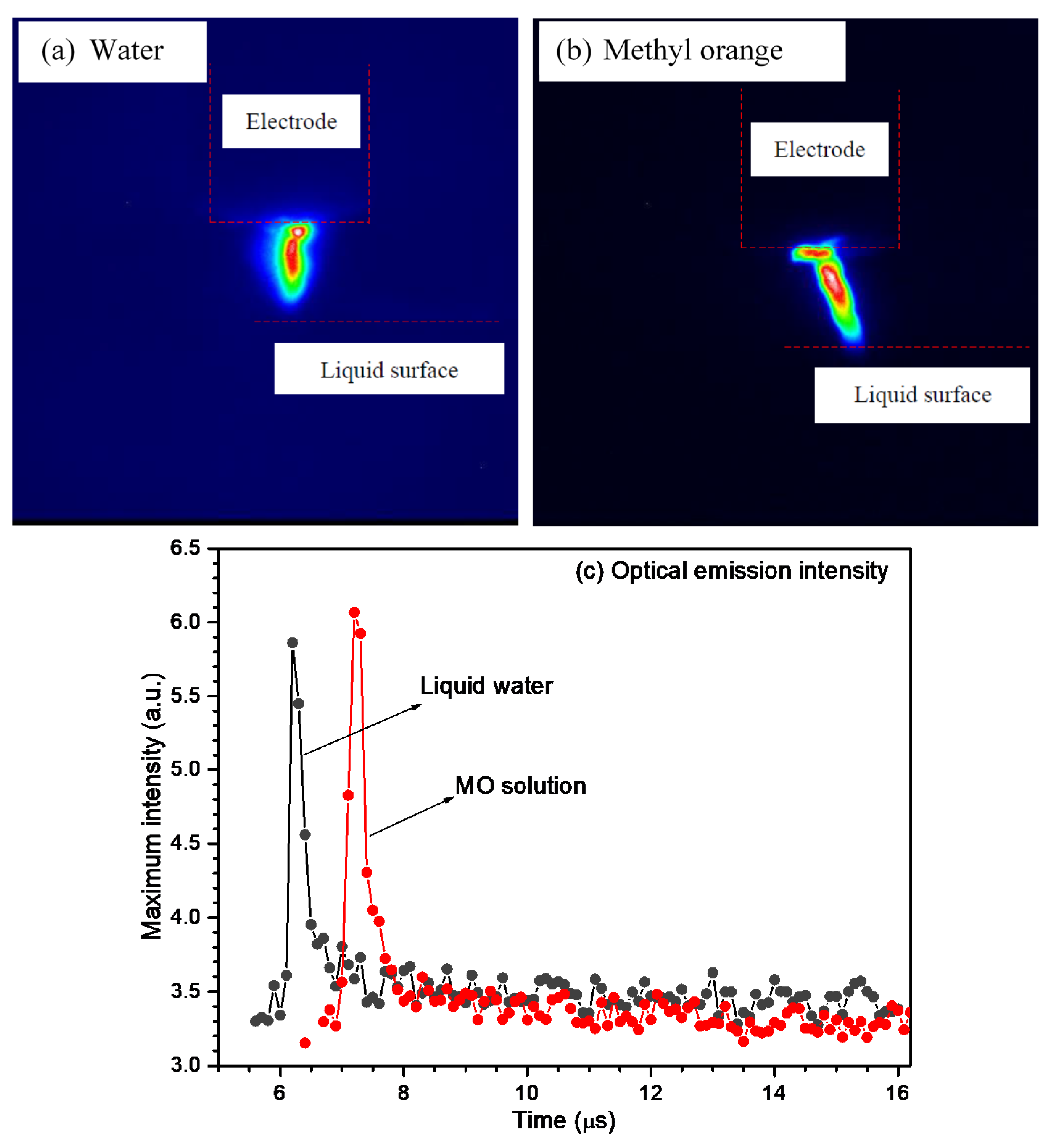
Figure 2 displays images of the arc plasma and its optical emission intensities when the copper rod acted as an electrode. Since the electrode and the surface of the aqueous solution could not be observed clearly without external lighting, the outlines were added in their shadows (see Figure 2a,b). These images were taken in a single discharge while applying high-voltage discharge plasma. It showed that the plasma stream channel quickly grew and propagated toward the surface of the aqueous solution as the cathode. It was found that the dimension and the display of the discharge plasma stream were influenced by the electrode material, discharge current, polarity, and solution content. Nevertheless, here, the form of the discharge plasma stream, including the stream head, that arrived on the liquid water or methyl orange solution surface was not observed. Since the plasma consisted of moving charged species, a certain current might also be involved during the growth and propagation process. Lastly, a voltage failure occurred when the plasma stream channel reached the surface of the liquid water or methyl orange solution. By using an ICCD camera, the optical emission of the discharge plasma stream was quantitatively determined for diverse exposure times [44].
The optical emission intensity was determined from the captured photograph of the discharge plasma stream propagation, which was associated with its optical refractive index. Hence, the maximum emission intensity as a function of the time and the peak position while applying the high-voltage discharge plasma could be observed. Figure 2c shows the optical emission intensity for the high-voltage discharge plasma at the surface of the liquid water or methyl orange solution and the gas phase. The delay time between the trigger signal and the camera opening was found to be around 5.5–6.0 μs; this may have been caused by the use of the gating electronics and cable. The maximum values of the currents were found at approximately 6.15–7.15 μs and 6.4–7.4 μs after the voltage breakdown for the liquid water or methyl orange solution as a medium, respectively. At these times, the maximum light intensities were also achieved; with increasing time, the light intensity seemed to be stable.
Nitrogen is recognized to possess prominent and multiple emission bands for all visible spectral light; hence, the presence of nitrogen molecule that originated from the methyl orange decomposition while applying the high-voltage discharge plasma also significantly contributed to the emitted light generation [45,46,47]. As a result, compared to the liquid water as a medium, it seemed that the high-voltage discharge plasma may have resulted in higher light intensity with the methyl orange solution as a medium. A similar phenomenon was also found when the SUS rod was used as a substitute for the copper rod electrode, where the delay time between the trigger signal and the camera opening occurred during the experiments (see Figure 3). In comparison with the liquid water as a medium, a higher light intensity with the methyl orange solution as a medium was also observed.
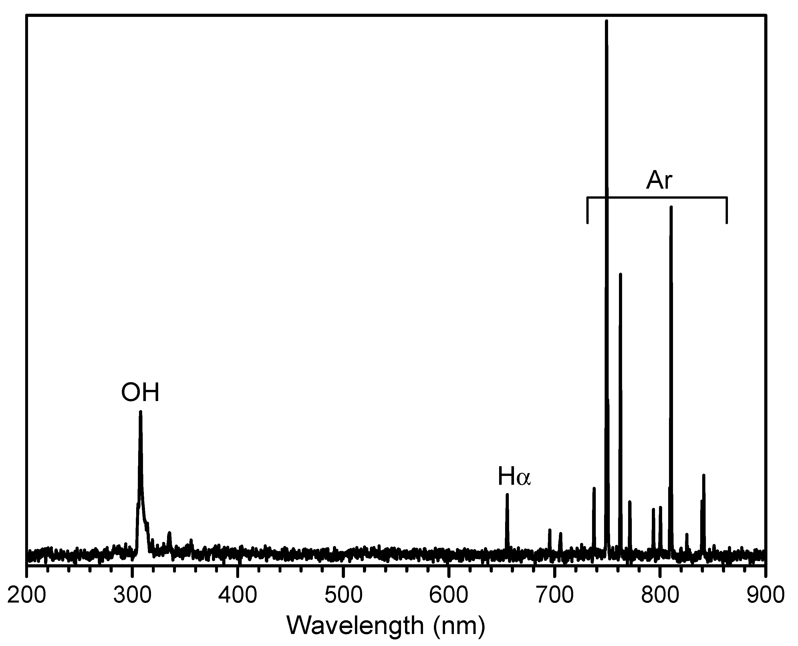
To observe the generated reactive species in the pulsed discharge plasma reactor system, the HR4000 Ocean Optics (Ocean Optics, Inc., Dunedin, FL, USA) equipment was used while applying the high-voltage discharge plasma through an optical fiber device. It is a simple, easy, and cost-effective analytical method. Figure 4 shows the optical emission spectroscopy (OES) spectrum of the pulsed discharge plasma that was introduced to the liquid water surface with the copper rod as an electrode. The spectrum illustrated that the emission of atomic argon was prominently discovered in the infrared zone between 700 to 800 nm. It indicated that the argon gas underwent multiple 4p–4s transition processes to decrease the occupancy of 4p levels during the experiments [22,48,49,50]. In this zone, the peak spectrum for atomic oxygen was discovered at around 777 nm. Based on the OES spectrum presented in this figure, the strong peak spectrum that was attributed to the existence of atomic hydrogen was found in the visible zone at around 656 nm. The OES spectrum also showed that the peak spectral emission at 309 nm, corresponding to the hydroxyl species, was detected with high intensity. This revealed that the hydroxyl species was produced while applying the high-voltage discharge plasma to the liquid water surface [48,51]. Hence, it can be said that applying the high-voltage discharge plasma to the liquid water surface in this reactor system may result in various chemical reactive species [49]. This figure also shows that the copper species were identified by the HR4000 Ocean Optics device that originated from the electrode erosion during the high-voltage discharge plasma treatment [52].
Figure 5 shows the conversion of methyl orange, i.e., the decoloration process, when the copper (CU–111487, 1.0 mm diameter, Nilaco, Tokyo, Japan) or the SUS rod (SUS–304, 751487, 1.0 mm diameter, Nilaco, Tokyo, Japan) was employed as an electrode to generate the discharge plasma. The applied power voltage was 15.4 kV with a pulse repetition rate of 4 pps. Methyl orange is one of the azo dyes that contain a large number of aromatic rings; this dye compound is also a group of chemical compounds that may result in increasing amounts of environmental pollution. Therefore, the removal process for this compound from wastewater has gained great attention [53,54,55,56,57,58,59,60,61,62,63,64]. As shown in Figure 5, the methyl orange compound was successfully decomposed into its derived compounds using the high-voltage discharge plasma treatment with the different types of metal electrodes. The result shows that the methyl orange conversion was around 0.3% and 64% when the experiment was carried out for 1000 pulsed discharges with SUS and copper rod as electrodes, respectively. It seems that the methyl orange conversion with the copper rod as an electrode was higher than that with SUS as an electrode under the same operating conditions. It is already known that copper metal possesses catalytic properties, while SUS metal provides good passivity features [65,66,67,68,69,70]. Gasparik et al. performed experiments for NOx removal by using a positive DC stream corona discharge with copper and SUS wires as electrodes [65]. By using the different types of electrodes that had opposite chemical properties, they observed the NOx removal rate in the water vapor environment. They reported that copper was the better electrode material for decomposing NOx into its derived compounds with water vapor as a medium. They also explained that the copper electrode was active and participated in the NOx removal during the treatment process, while the SUS electrode remained inactive during the treatment process. Similar results were also reported by Morvova when she carried out experiments for carbon dioxide conversion by using a DC corona discharge with diverse electrode materials with water vapor as the medium [66]. A high conversion efficiency of CO2 was obtained when the copper wire was used as an electrode; conversely, a low conversion efficiency of CO2 was discovered when the SUS wire acted as the electrode. Consequently, as displayed in Figure 5, while employing the copper rod as the electrode, the methyl orange decoloration rate could reach higher values than while using the SUS rod as the electrode under the same operating conditions.
As mentioned before, for 1000 pulsed discharges, the methyl orange conversion was around 0.3% and 64% with SUS and copper rod as the electrodes, respectively. However, this conversion could approach 100% when the number of discharge plasma pulses was increased to 20,000 pulses. The pulse repetition rate and increased number of pulses may have resulted in increased energy and an increased number of high-energy electrons, which could improve the reactive species production. The transferred amount of energy probably also proportionally increased the amount of applied discharge plasma. More energetic electrons bombarded the water molecules to increase the reactive species quantity that would interact and react with the methyl orange compound, resulting in the high decoloration rate, and therefore, an improved methyl orange decoloration process. As a result, as shown in Figure 5, the methyl orange decoloration rate increased with increasing the amount of high-voltage discharge plasma [38,39].
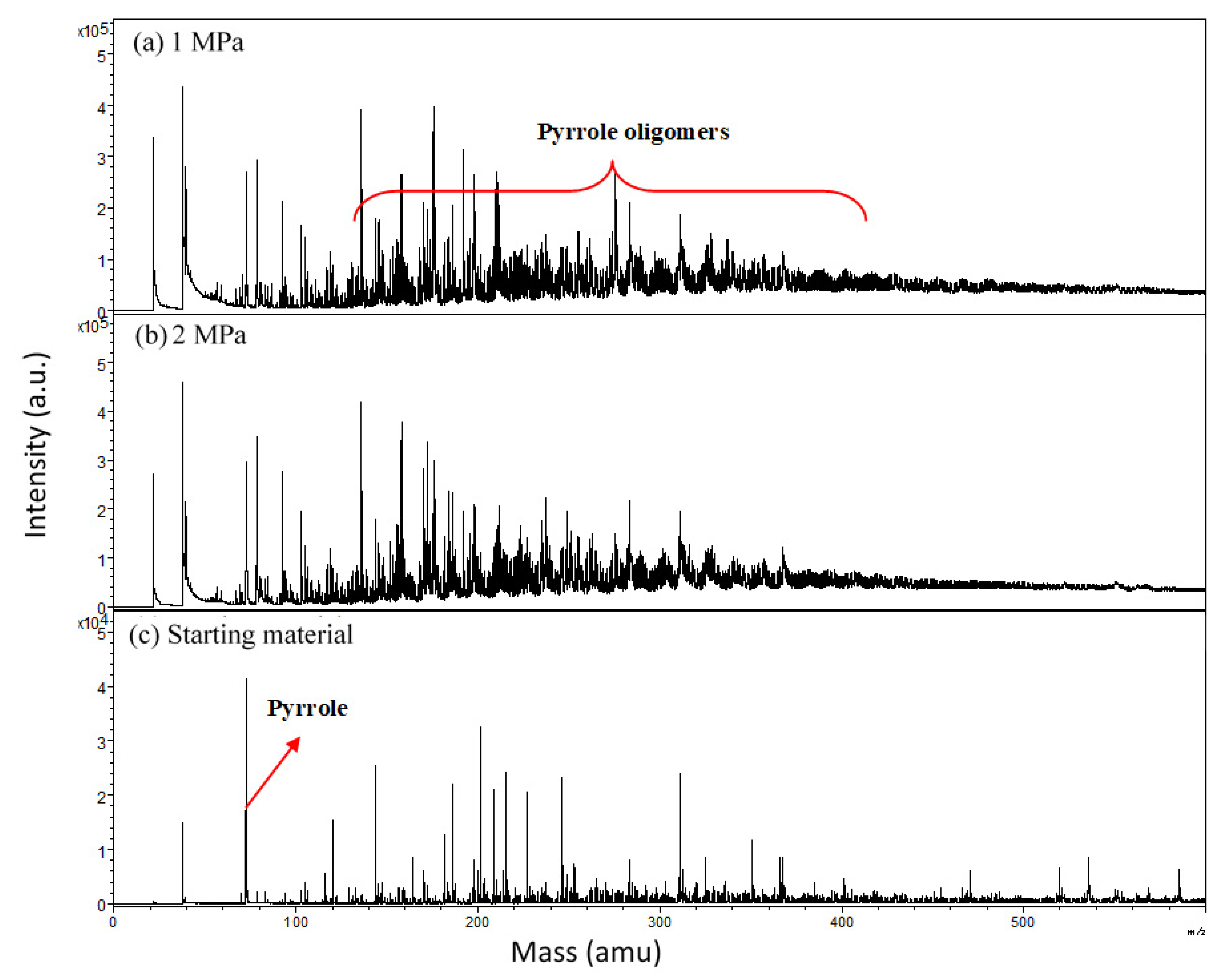
In addition to the methyl orange decoloration, high-voltage discharge plasma in the gas-liquid water environment was also employed to oligomerize the pyrrole compound. Pyrrole is known as one of the important heterocyclic organic compounds. Its formula is C4H4NH, where it consists of a five-membered ring that includes a nitrogen atom. This compound is an electron-rich ring and is easily oxidized [70,71,72]. Figure 6 shows the MALDI-TOF mass spectra of pyrrole after the high-voltage discharge plasma treatment under diverse operating pressures. The MALDI-TOF-MS analysis technique possesses the ability to remove the heat energy produced by rapid laser heating; therefore, the polymer compounds vaporize almost without decomposition and can be easily identified [73,74,75].
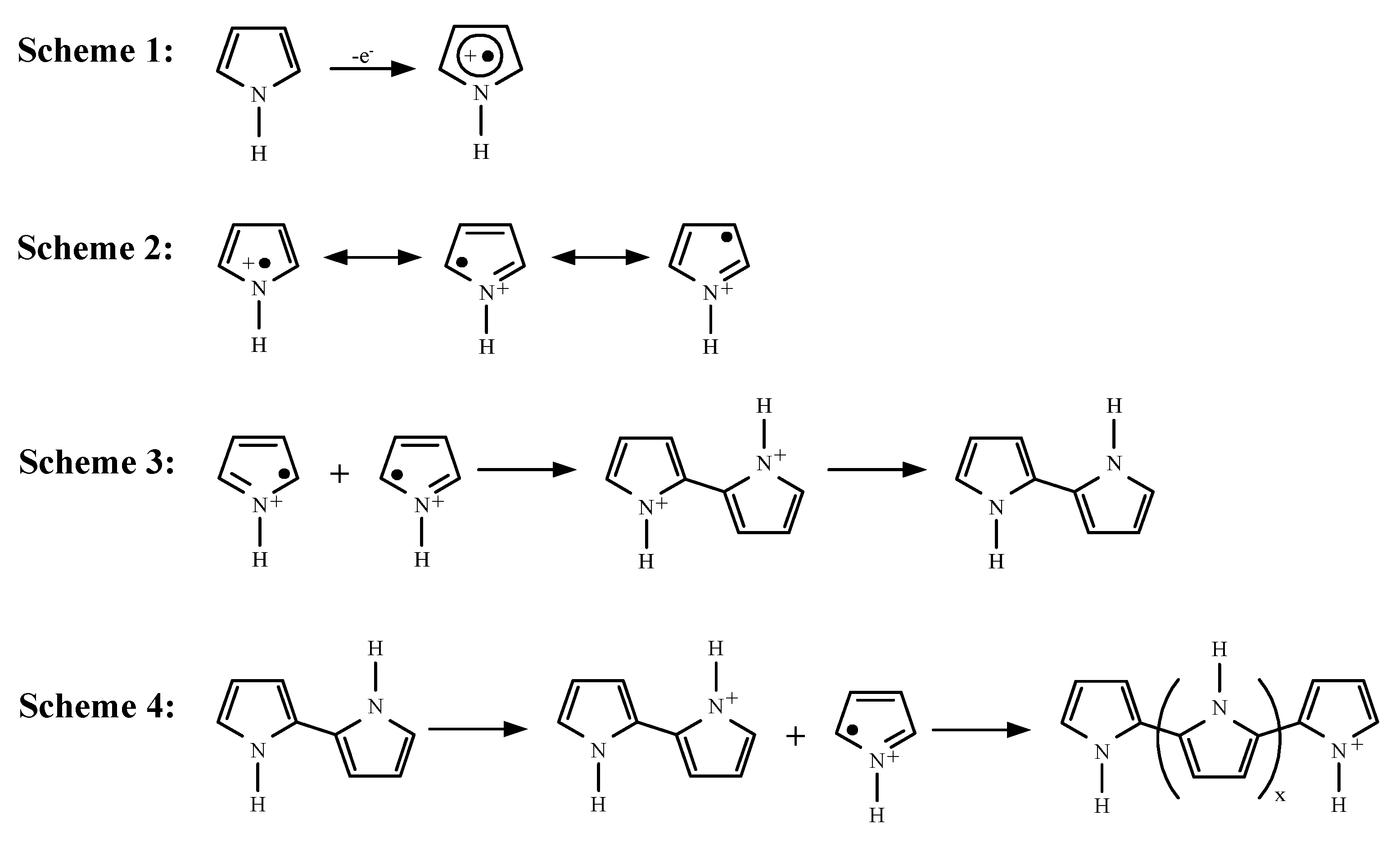
This analysis technique is able to analyze and give polymer molecular weight information with high reliability; hence, as displayed in this figure, the analysis results of the pyrrole-derived compound that were found using MALDI-TOF-MS are described in terms of its molecular weight and presented in units of m/z. Clearly, the peak spectra of the pyrrole-derived compound were distributed and separated by the monomer unit mass under each experimental condition. It shows that the pyrrole-derived compounds with the higher molecular weights were generated after the high-voltage discharge plasma treatment, where the pyrrole-derived compounds with molecular weights around 130–440 amu were the most prominently generated. Perhaps, the pyrrole oligomer was formed via breaking pyrrole chemical structures. The reactive species interacts and reacts with the pyrrole compound through several pathways, resulting in the reactive pyrrole-derived compound radicals. This pyrrole-derived compound radical may undergo advanced reactions to produce the oxidized pyrrole-derived compound substrate. Next, the breaking of this pyrrole ring leads to the formation of lower molecular weight compounds as inferior reaction products. Simultaneously, the crosslinking reaction as a major reaction occurs, where this reaction takes place on the amine group or another reactive site of pyrrole’s chemical structure to result in a pyrrole-derived compound with a high molecular weight [76,77,78,79,80]. Although the reaction mechanism for pyrrole decomposition into its derived compound is complex, based on the MALDI-TOF-MS analysis, a plausible reaction pathway for pyrrole oligomerization was proposed and is presented in Figure 7. The pyrrole oligomerization process involved oxidation and dimerization steps. It was then followed by aromatization and the pyrrole dimer oxidation [81,82,83,84]. In Scheme 1, the oxidation of pyrrole monomer occurred to form pyrrole radical cations. This was followed by the formation of some resonance cations (Scheme 2). The pyrrole radical cation was probably generated in a high quantity since the process of electron transfer usually is very rapid. As a result, the dimerization reaction of the pyrrole compound from its radical cation occurred, at least from two radical cations of pyrrole (see Scheme 3). At the same time, the pyrrole dimers were oxidized to generate the cation radical of the pyrrole dimer during this oligomerization reaction process. Under this condition, the unpaired electrons were delocalized on the two pyrrole compound rings. Hence, the pyrrole monomer oxidation potential became higher than the pyrrole dimer oxidation potential. It is well known that higher-molecular-weight compounds, including pyrrole oligomers, are more easily oxidized than lower-molecular-weight compounds [85,86,87]. Therefore, as illustrated in Scheme 4, the oxidation reaction of pyrrole dimers took place more effectively than pyrrole monomers. Next, via the prolongation of these reaction steps, the pyrrole oligomer was generated.
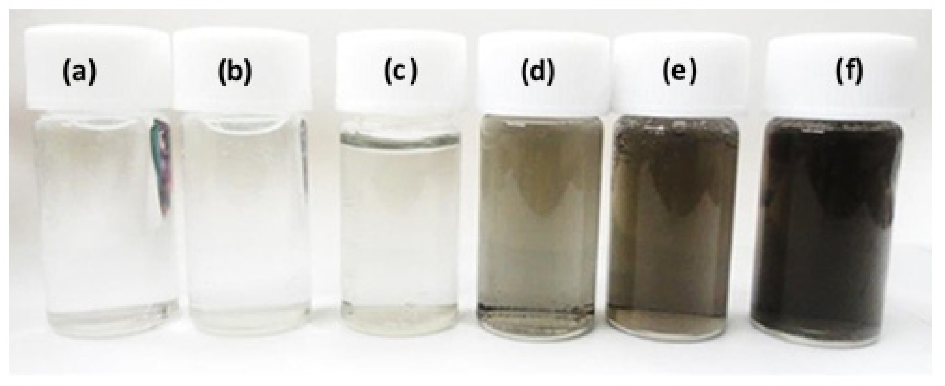
It is known that carbon materials can be synthesized by applying a high-voltage discharge plasma in a liquid medium [88,89,90,91,92,93,94,95]. It is a simple technique, where, as a first approach, carbon materials can be originated from electrode erosion with graphite as electrodes. The second approach is applying high-voltage discharge plasma directly in an organic solvent medium. This means that the carbon materials do not originate from electrodes, but they are generated from the degradation of an organic solvent as a precursor source for carbon. Figure 8 shows the photographs of solution products after applying high-voltage discharge plasma to the liquid water solution surface at various argon gas pressures with the copper rod as an electrode. This solution consisted of distilled water and a glycine compound with a concentration of 100 g/L. It was loaded in the SUS reactor at around 7.0 mL and treated with a DC pulsed voltage of 18.6 kV with 10,000 pulses and a 4 Hz pulse repetition rate. The titanium rod (TI-451485, 1.0 mm diameter, Nilaco, Tokyo, Japan) was used as a metal electrode. Before applying the high-voltage discharge plasma, the liquid water solution was colorless (transparent). This solution color changed to black (dark) after applying the high-voltage discharge plasma. However, this changed color was only found when the experiment was carried out under high argon pressure conditions of more than 1 MPa. The changed solution color probably indicated that the carbon solid materials were formed from the glycine degradation reaction while applying the high-voltage discharge plasma. Even though the reason why the carbon solid materials were only generated under high-pressure conditions is not clear yet, as described above, when the high-voltage discharge plasma was applied in the gas-liquid water environment, the physical and chemical effects, i.e., shock wave generation, strong electrical field, ultraviolet radiation, and diverse radicals generation, may happen simultaneously [6,7,11,12,13,14,15,16,17,96,97]. The reactive chemical species that have high reactivity, i.e., hydrogen peroxide molecules, hydrogen molecules, oxygen molecules, and hydroxyl radicals, may interact and react with the glycine compound. This reaction may cleave the glycine structures containing an amine site and a carboxyl site through deamination and decarboxylation [98]. When the environmental pressure was increased, the argon solubility in liquid water may also increase.
At room temperature (25 °C), the argon solubility is around 0.252 × 10⁻⁴ at a pressure of 0.1 MPa, while it could approach 9.28 × 10⁻⁴ at a pressure of 4 MPa [99,100]. Next, shorter radiation pulse plasma is produced and a large diffusive cone, resulting in discharge plasma, also happens [37,101]. At the higher operating pressures, when the pulsed power energy was calculated from the applied voltage and current waves (see Figure 1), the charged energy was higher at the higher operating pressures. This means that the pulsed power energy supplied into this plasma reactor system was higher at higher operating pressures. Moreover, at the higher operating pressures, the emission intensity of the pulsed discharge plasma was higher. This may have promoted the reactive species generation in large quantities, which were supplied to the liquid water solution containing the glycine compound. Due to these phenomena, the carbon materials generation from the decomposition of glycine compound also increased with increasing operating pressure. Even though the reason for this is not clear yet, it explains why the carbon material was formed only at the high operating pressures [40,41,42,43].
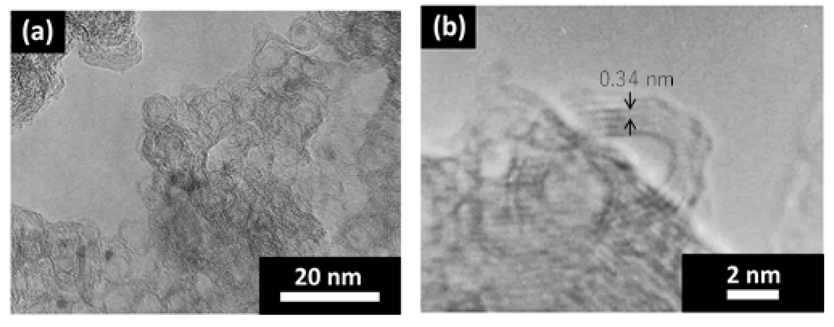
Figure 9 shows the typical Raman spectrum for the carbon materials from the decomposition of the glycine compound by applying the high-voltage discharge plasma at a pressure of 4 MPa with 100,000 applied pulses. By using this analysis technique, based on the chemical bonds attached with the various substances existing in the materials, the information for the various chemical fingerprints can be obtained. Raman spectroscopy analysis is a complementary analysis technique that can be used for various materials (organic and inorganic materials). This analysis technique is a convenient, non-destructive, and non-contact method that only needs small sample amounts. Furthermore, the analysis period is also relatively short [43,102,103,104]. It seems that the absorption peaks at 1340, 1582, and 2670 cm−1 corresponded to the D, G, and 2D band modes, respectively, which were clearly observed in the Raman spectra of solution product, where the D band exhibits disordered carbon mode and the G band exhibits ordered carbon mode [105,106]. Obviously, the absorption peak at around 2920 cm−1, which was associated with the hydroxyl group, was also found in this Raman spectrum [107,108,109]. Panickar et al. explained that the G mode is attributed to the stretching motion of the sp2-hybridized carbon atoms’ bond in pairs, whereas the D mode is associated with the breathing motion of the sp2-hybridized carbon atoms in rings [110]. Even though these absorption bands are general bands in the spectra analysis using Raman spectroscopy for various disordered, amorphous, and noncrystalline forms of carbon atoms, they were not discovered when the glycine solution was analyzed using Raman spectroscopy device before the high-voltage discharge plasma treatment. Figure 10 exhibits the images of the carbon products when the liquid product was examined using the HRTEM device. It seems that the carbon materials possessed the multi-walled carbon nanocapsule with walls consisting of several graphene layers ranging from two to six layers. The gaps between the atomic layers in these carbon products were around 0.34 nm, where the 0.34 nm distance can be associated with the lattice spacing of graphene layers [111,112,113,114]. This revealed that the carbon materials could be generated by applying the high-voltage discharge plasma on the glycine solution through deamination and decarboxylation reactions [40,41,42,43,98]. Li et al. conducted experiments for graphene nanosheet synthesis by applying pulsed arc discharge plasma to petroleum asphalt with a liquid water medium [111]. The experiments were performed using pulsed DC power at room temperature with a 20 kHz pulse frequency, 2 µs pulse width, and 25 µs between the positive and negative pulses. They reported that, as with bulk graphite, the obtained graphene nanosheet had a layer distance of around 0.34 nm. The same results were also obtained when Phan et al. performed experiments for the nitrogen-doped metal nanoparticle covered in a few graphene layers by using solution plasma with a 1.0 µs pulse width and a 30 kHz repetition frequency [114].
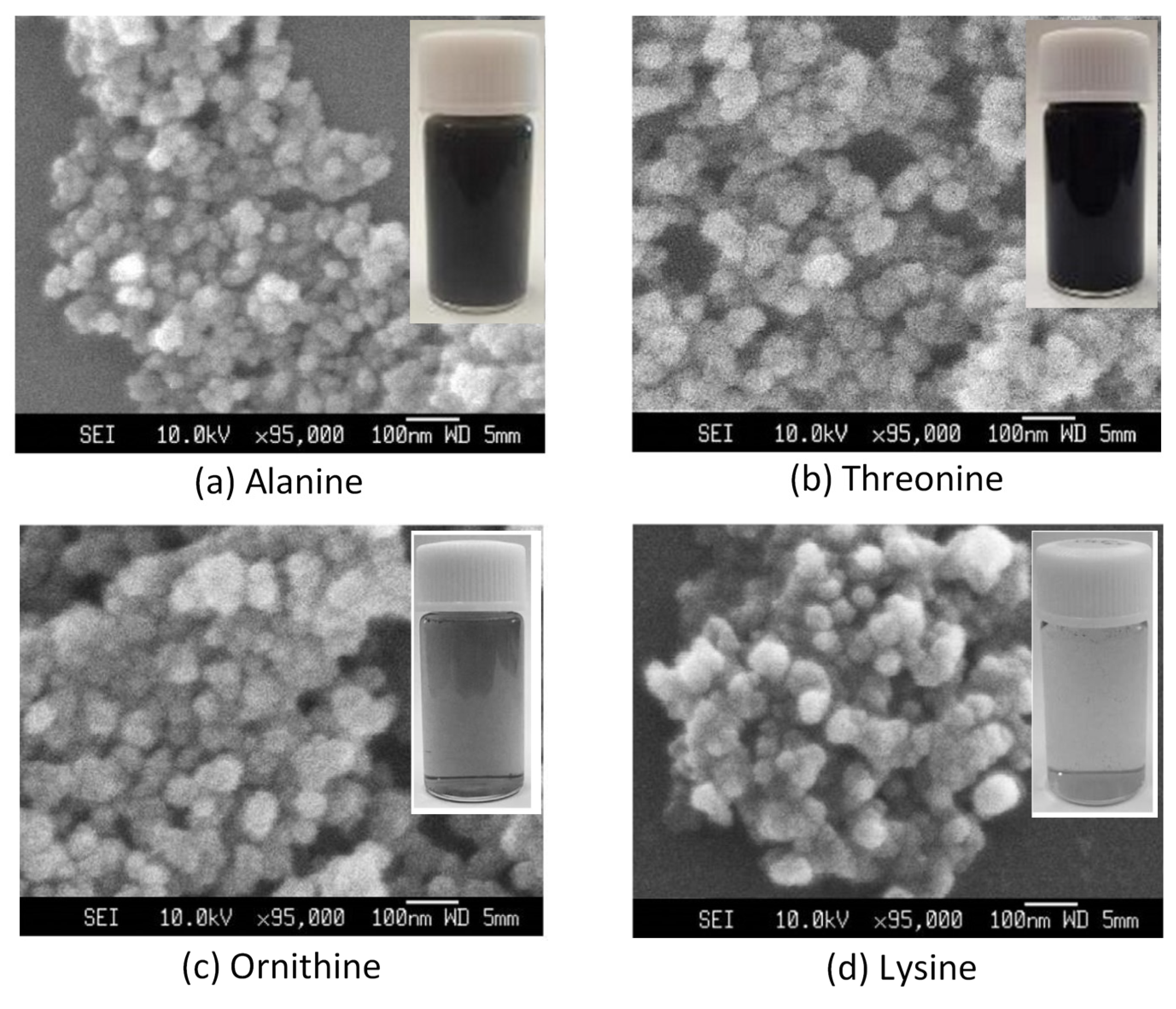
The high-voltage discharge plasma was also applied to the liquid water solution surface containing other amino acids to generate hydrophilic carbon materials, where this carbon material has several potential applications in environmental and medical fields [115,116,117,118]. A lysine, alanine, threonine, or ornithine compound was used as a starting material to substitute the glycine compound. As amino acid compounds, these organic compounds also possess two hydrophilic sites: amine and carboxyl sites. Via the deamination and decarboxylation reaction of this amino acid compound, the carbon-based material can be modified from hydrophobic to hydrophilic due to the attachment of hydroxyl or amino sites on the surface of the carbon material. As a result, the synthesized carbon material was dispersible in liquid water. Figure 11 exhibits the SEM images of the carbon material products and their photographs formed from the decomposition reaction of alanine, threonine, ornithine, and lysine compounds when the experiments were carried out under pressurized argon gas at 4 MPa with an 18.6 kV applied voltage, 20,000 and 40,000 pulses, and a 4 Hz pulse repetition rate. When the liquid water solution containing alanine or threonine compounds was used as the starting material, after the applying 20,000 pulses of the arc discharge plasma, the liquid water solution color changed from colorless to black. This implied that the carbon materials were generated. In contrast, the carbon material was not visually observed for the same number of pulses when the liquid water solution comprising lysine or ornithine was used as the starting material. Nevertheless, when the number of pulses of the arc discharge plasma was increased to 40,000 pulses, the generation of carbon material from those feed solutions occurred. As shown in the inset photographs in Figure 11c,d, when comparing ornithine and lysine compounds as starting materials, the carbon material was more easily produced when the ornithine compound acted as the carbon source.
As mentioned before, the deamination and decarboxylation reactions occur during the carbon material generation from amino acid compounds, but these reactions seem difficult to initiate when the carbon material was synthesized from amino acids comprising longer straight carbon bonds (lysine or ornithine) due to the steric hindrance of the larger molecules [119,120,121,122]. In turn, this may lead to the slower formation of the carbon material from the amino acid compounds with longer carbon bonds. Hence, it could be said that it was easier to generate the carbon materials from amino acid compounds with shorter carbon bonds compared to those with longer straight carbon bonds. Figure 11 shows the morphology of carbon materials generated from various amino acid compounds by applying the high-voltage discharge plasma. Prior to the SEM characterization, the aqueous solution products were frozen via freeze-drying to separate the water content in the solution (Eyela FDU-1200, Rikakikai Co. Ltd., Tokyo, Japan). Each collected sample possessed the same spherical morphology. However, it seems that the particle sizes of the carbon materials were diverse. This might have been affected by the different kinds of amino acid compounds that were used as carbon sources. When the amino acid compound with longer carbon bonds was employed as a carbon source for carbon material production, the low speed of carbon material generation occurred. This phenomenon probably affected and caused the larger sizes of the generated carbon materials.
Aside from the hydrophilic carbon material generation from various amino acid compounds, applying the high-voltage discharge plasma under high-pressure conditions in the gas-liquid water environment was also utilized to synthesize metal nanoparticles. Generally, metal nanoparticles can be synthesized in several ways, i.e., using biological, physical, and chemical methods [43,123,124,125,126,127,128]. In the chemical or biological methods, some molecules or atoms are usually constructed to form nanoparticles, whereas in the physical methods, decreasing the bulk material size can be used to produce nanoparticles. The most general way to produce nanoparticles involves chemical techniques, which require a simple device and involve a convenient and easy process. However, in chemical processes, an organic solvent or chemical reagent is added to generate nanoparticles. Consequently, at the end of the chemical process, harmful residues might be formed and found together with the nanoparticle products. In the biological processes, the organic solvent or the chemical reagent is replaced by a living organism to generate nanoparticles. The nanoparticle formation using this method is an environmentally friendly and inexpensive process. However, its reproducibility is limited and it also can result in producing a biological contaminant residue as an unwanted product. Compared to the chemical or biological process, in physical processes, the unwanted product can be discarded at the end of the process. However, the physical method generally has a high operating cost.
Figure 12 exhibits the STEM image of the nanoparticle products and their elemental compositions when the experiment was conducted under pressurized argon gas at 3 MPa with a titanium rod as the electrode, 18.6 kV applied voltage, 4 Hz pulse repetition rate, and 20,000 pulses. The STEM assembled with the EDS device is a simple method to characterize nanoparticles and has the ability to identify the chemical elements in the materials. The STEM image indicated that the titanium element was found in the collected nanoparticle products (see the chemical element color coding in Figure 12). Normally, the erosion of the electrode while applying high-voltage discharge plasma is an undesirable occurrence and this phenomenon should be avoided. However, here, the erosion of the titanium rod electrode was utilized as a material source for metal nanoparticle formation. Thus, the status of the electrode erosion phenomenon was changed from an undesired product (contaminant) to the wanted process products. Kolikov et al. treated the wastewater from the sewerage by using high-voltage discharge plasma with various metal rods as electrodes, including titanium metal [129]. During the treatment process, they found that the erosion of the titanium rod electrode occurred due to applying the high-voltage discharge plasma in the wastewater solution, resulting in metal nanoparticle formation. Saito and Akiyama summarized the effects of applying high-voltage discharge plasma to a liquid solution medium for metal nanoparticle generation [130]. They stated that bulk metal applied to the liquid solution medium not only serves as an electrode but also as a metal ion source material for metal nanoparticle formation. Kim and Kim also found that applying high-voltage discharge plasma in a liquid solution medium is an environmentally friendly, versatile, and simple method for metal nanoparticle production [131]. Accordingly, it could be said that titanium dioxide nanoparticles were formed under pressurized argon gas by applying the high-voltage discharge plasma on the surface of a liquid water solution containing glycine through erosion of the titanium rod electrode.
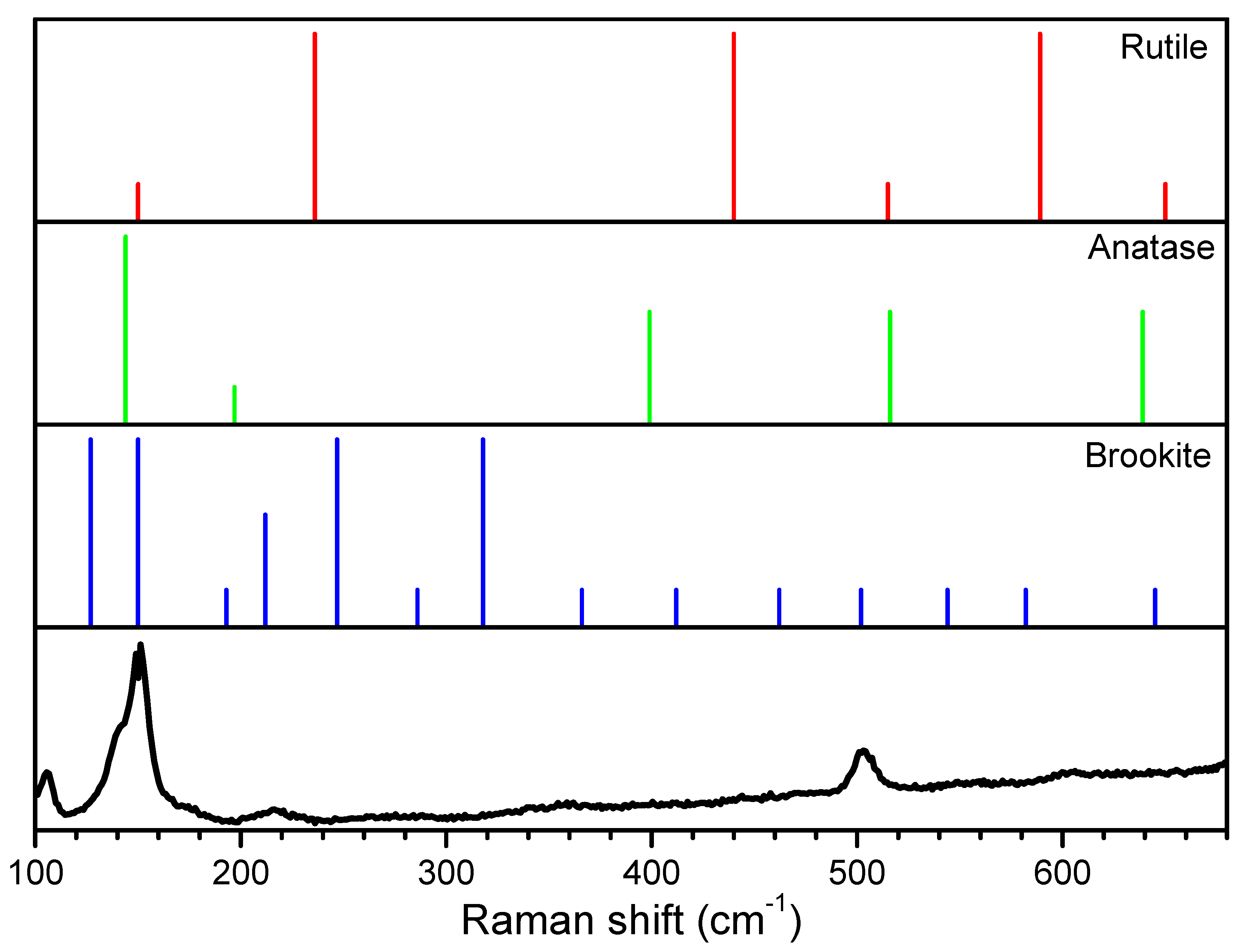
As with the characterization of the carbon material using Raman spectroscopy, the collected titanium dioxide nanoparticle products were also characterized using Raman spectroscopy. This analysis technique allows for observing the symmetric stretching vibration of O-Ti-O in titanium dioxide particles that are associated with the Eg peak. The symmetric and antisymmetric bending vibrations of O-Ti-O in titanium dioxide particles corresponding to the B1g and A1g peaks, respectively, could also be observed [132,133,134,135]. Figure 13 exhibits the typical Raman spectrum for titanium dioxide nanoparticles produced using the high-voltage discharge plasma under pressurized argon gas. Obviously, the peaks in the Raman spectra with strong intensities were discovered at the 502, 212, and 150 cm−1 bands. In agreement with the Raman spectra of rutile, anatase, and brookite as reference patterns for titanium dioxide polymorphs, the bands in this Raman spectra can be attributed to the brookite structural phase of titanium dioxide nanoparticles. Here, the spectrum peaks of B1g at the 502 and 212 cm−1 bands and the spectrum peak of Eg at the 150 cm−1 band were associated with the symmetric bending and stretching vibrations of O-Ti-O in titanium dioxide nanoparticles with the brookite structure form [134,135]. The recent information on the energy-related application, properties, modification, and synthesis of titanium dioxide as transparent semiconductors in n- and p-type were reviewed by Anitha et al. [134]. They listed that nine A1g, nine B1g, nine B2g, and nine B3g of Raman active modes were found and predicted for titanium dioxide particles with the brookite structure form. These Raman active modes were assigned as follows: B3g (172, 287/288, and 545 cm−1), B2g (365/366, 395/396, 460/461, and 583 cm−1), B1g (133, 213/214, 322/323, and 501/502 cm−1), and A1g (127/128, 155/156, 194, 245/246, 412, and 637/638 cm−1). Srivatsa et al. performed experiments for the brookite titanium dioxide particle generation using the plasma improved chemical vapor deposition method under the impact of energetic ions [136]. They reported that the ions under the dense conditions resulting from applying a high bias voltage can provide enough energy to promote the restructuring of deposited titanium dioxide nanoparticles. Furthermore, even though the deposited titanium dioxide nanoparticle needed a specific amount of energy to achieve a specific structure, such as by increasing the deposition temperature, Srivatsa et al. explained that the specific energetic circumstance could be achieved for the specific structure formation by applying a bias voltage during the high-voltage discharge plasma treatment at ambient temperature [136].
Next, the titanium dioxide nanoparticle products were subjected to a high-resolution TEM (HRTEM) device. Using this characterization technique, information concerning the atomic structure of titanium dioxide nanoparticles was obtained. Figure 14 exhibits the HRTEM images of titanium dioxide nanoparticles (a) and titanium dioxide nanoparticles containing carbon material (b), respectively. As exhibited in Figure 14a, the interplanar spacing of the lattice fringes in the range of 0.36–0.35 nm was obviously discovered in the titanium dioxide nanoparticle products’ crystal planes. This interplanar spacing may be associated with the crystal plane with a brookite structure as a titanium dioxide nanoparticle with an orthorhombic phase [137,138]. In nature, titanium dioxide particles are known to primarily have three crystalline polymorphic phases: rutile (tetragonal), anatase (tetragonal), and brookite (orthorhombic). Of these crystalline forms, the anatase and brookite polymorphs are metastable. They can be shifted into the rutile polymorphic form, while the rutile polymorph is known as the most stable phase. However, Ge et al. mentioned that titanium dioxide particles comprising the anatase or brookite crystalline polymorphic phases at the nanoscale are believed to be more stable due to their lower surface energy when they observed the titanium dioxide nanostructured particles as one-dimensional shapes for energy and environmental applications [139]. Moreover, the crystalline polymorph of brookite or anatase particles seems to possess the same lattice fringe-spacing range around 0.35 nm, such that they can be attributed to brookite (210) or anatase (101) plane particles [140,141]. Therefore, it is not easy to differentiate between brookite or anatase structural forms due to their similar lattice fringe-spacing range. Nevertheless, according to the results given using the Raman spectroscopy analysis (see Figure 13), as the major product of titanium dioxide nanoparticles, the collected titanium dioxide nanoparticle products seemed to possess the brookite structure form [136,142]. As mentioned above, there are two phenomena occurring when applying high-voltage discharge plasma in the gas-liquid water system containing an organic substance, namely, electrode erosion and organic substance decomposition. The electrode erosion may generate metal nanoparticles [129,130,131,143,144,145], and the decomposition reaction of an organic substance, e.g., glycine compound, may generate carbon materials [37,38,39,40,41,42,43]. Hence, during the high-voltage discharge plasma treatment, the interaction between the carbon and titanium atoms produced from the decomposition reaction of the glycine compound and the erosion of titanium rod electrode occurred and could result in titanium carbide (TiC) nanoparticles (see Figure 14b). This shows that the lattice fringe spacing around 0.22–0.24 nm was clearly discovered in the collected titanium dioxide nanoparticle products. This lattice fringe distance could be attributed to the (111) plane of titanium carbide [146]. Haghighi and Poursalehi observed the effect of carbon/hydrogen and carbon/oxygen ratios on the titanium carbide nanoparticle formation by applying arc discharge plasma in organic solvents as the media [147]. They reported that titanium carbide nanoparticles could be produced from the interaction between titanium dioxide and carbon under arc discharge plasma conditions. Furthermore, they explained that the high carbon/hydrogen ratios are suitable for pure titanium carbide nanoparticle synthesis under arc discharge plasma conditions, whereas, under the same conditions, the high carbon/oxygen ratios favor generating oxide-carbide composite nanostructures.

4. Conclusions and Future Directions

High-voltage discharge plasma under a high-pressure argon gas environment (~4 MPa) was applied in the gas-liquid water system for the water pollutants’ decomposition and the synthesis of nanoparticles. The experiments were conducted at room temperature in the batch-type system with a pulsed DC power supply as a discharge plasma source ranging from 15.4 to 18.6 kV. The results showed that the electrode materials, the pulse repetition rates, the number of applied pulses, and the applied voltage had a significant effect on the degradation reactions of the organic compounds. In addition to the carbon solid materials from the glycine degradation that were produced while applying high-voltage discharge plasma under high-pressure conditions, the Raman spectra and the HRTEM images revealed that titanium dioxide with brookite structure and titanium carbide nanoparticles were also produced under these conditions. Even though applying the high-voltage discharge plasma under a high-pressure argon gas environment was demonstrated for water pollutants’ degradation and nanoparticle synthesis, several challenges remain, mainly due to most discharge plasma systems being designed for small-scale processes, including our discharge plasma system. Hence, more research efforts are required to successfully produce plasma technology that is more suitable for industrial-scale applications. Nevertheless, it can be proposed that our discharge plasma system is an applicable method for advanced organic compound decomposition and metal-based nanoparticle synthesis using the utilizing electric field produced by high-voltage discharge plasma.

Author Contributions

Conceptualization, W.D., S.M., H.K., Y.Z. and M.G.; methodology, W.D., S.M., H.K., Y.Z. and M.G.; writing—original draft preparation, W.D. and S.M.; writing—review and editing, W.D., S.M., H.K., Y.Z. and M.G.; visualization, M.G.; supervision, M.G.; project administration, H.K. and M.G. All authors have read and agreed to the published version of the manuscript.

Funding

This research was funded by JSPS KAKENHI, grant number JP20H02515 and JST SICORP, grant number JPMJSC18H1, Japan. The APC was funded by JP20H02515 and JPMJSC18H1.

Data Availability Statement

The data presented in this study are available on request from the corresponding author.

Conflicts of Interest

The authors declare no conflict of interest.

References

  1. Conrads, H.; Schmidt, M. Plasma generation and plasma sources. Plasma Sources Sci. Technol. 2000, 9, 441. [Google Scholar] [CrossRef] [Green Version]
  2. Lieberman, M.A.; Lichtenberg, A.J. Principles of Plasma Discharges and Materials Processing, 2nd ed.; John Wiley and Sons: Hoboken, NJ, USA, 2005; p. 7. [Google Scholar]
  3. Lu, X.; Reuter, S.; Laroussi, M.; Liu, D. Nonequilibrium atmospheric pressure plasma jets: Fundamentals, diagnostics, and medical applications; CRC Press: Boca Raton, FL, USA, 2019; pp. 9–26. [Google Scholar]
  4. Klimov, A.S.; Bakeev, I.Y.; Oks, E.M.; Tran, V.T.; Zenin, A.A. Plasma electron source for generating a ribbon beam in the forevacuum pressure range. Rev. Sci. Instrum. 2020, 91, 043505. [Google Scholar] [CrossRef]
  5. Zolotukhin, D.B.; Burdovitsin, V.A.; Oks, E.M. Plasma formation near the beam collector of a forevacuum−pressure plasma−cathode electron beam source. Phys. Plasma 2020, 27, 113509. [Google Scholar] [CrossRef]
  6. Locke, B.R.; Sato, M.; Sunka, P.; Hoffmann, M.R.; Chang, J.S. Electrohydraulic discharge and nonthermal plasma for water treatment. Ind. Eng. Chem. Res. 2006, 45, 882–905. [Google Scholar] [CrossRef]
  7. Bruggeman, P.; Leys, C. Non-thermal plasmas in and in contact with liquids. J. Phys. D: Appl. Phys. 2009, 42, 053001. [Google Scholar] [CrossRef]
  8. Parvulescu, V.I.; Magureanu, M.; Lukes, P. Plasma Chemistry and Catalysis in Gases and Liquids; John Wiley and Sons: Weinheim, Germany, 2012; pp. 185–188. [Google Scholar]
  9. Nishiyama, H.; Nagai, R.; Niinuma, K.; Takana, H. Characterization of DBD multiple bubble jets for methylene blue decolorization. JFST 2013, 8, 65–74. [Google Scholar] [CrossRef] [Green Version]
  10. Guo, H.; Jiang, N.; Wang, H.; Lu, N.; Shang, K.; Li, J.; Wu, Y. Degradation of antibiotic chloramphenicol in water by pulsed discharge plasma combined with TiO2/WO3 composites: Mechanism and degradation pathway. J. Hazard. Mater. 2019, 371, 666–676. [Google Scholar] [CrossRef]
  11. Joshi, R.P.; Thagard, S.M. Streamer-Like Electrical Discharges in Water: Part II. Environmental Applications. Plasma Chem. Plasma Process 2013, 33, 17–49. [Google Scholar] [CrossRef]
  12. Fujita, H.; Kanazawa, S.; Ohtani, K.; Komiya, A.; Sato, T. Spatiotemporal analysis of propagation mechanism of positive primary streamer in water. J. Appl. Phys. 2013, 113, 113304. [Google Scholar] [CrossRef]
  13. Claverie, A.; Deroy, J.; Boustie, M.; Avrillaud, G.; Chuvatin, A.; Mazanchenko, E.; Demol, G.; Dramane, B. Experimental characterization of plasma formation and shockwave propagation induced by high power pulsed underwater electrical discharge. Rev. Sci. Instrum. 2014, 85, 063701. [Google Scholar] [CrossRef]
  14. Sun, B.; Xin, Y.; Zhu, X.; Gao, Z.; Yan, Z.; Ohshima, T. Effects of shock waves, ultraviolet light, and electric fields from pulsed discharges in water on inactivation of Escherichia coli. Bioelectrochemistry 2018, 120, 112–119. [Google Scholar] [CrossRef]
  15. Abramov, V.O.; Abramova, A.V.; Cravotto, G.; Nikonov, R.V.; Fedulov, I.S.; Ivanov, V.K. Flow−mode water treatment under simultaneous hydrodynamic cavitation and plasma. Ultrason. Sonochem. 2021, 70, 105323. [Google Scholar] [CrossRef]
  16. Fan, J.; Wu, H.; Liu, R.; Meng, L.; Sun, Y. Review on the treatment of organic wastewater by discharge plasma combined with oxidants and catalysts. Environ. Sci. Pollut. Res. 2020, 28, 2522–2548. [Google Scholar] [CrossRef]
  17. Akiyama, H.; Akiyama, M. Pulsed Discharge Plasmas in Contact with Water and their Applications. IEEJ Trans. Electr. Electron. Eng. 2021, 16, 6–14. [Google Scholar] [CrossRef]
  18. Kosinskaya, I.V.; Polozova, L.P. A continuum source for the near vacuum region of the spectrum. J. Appl. Spectrosc. 1969, 11, 1151–1152. [Google Scholar] [CrossRef]
  19. Takamatsu, T.; Uehara, K.; Sasaki, Y.; Miyahara, H.; Matsumura, Y.; Iwasawa, A.; Ito, N.; Azuma, T.; Kohno, M.; Okino, A. Investigation of reactive species using various gas plasmas. RSC Adv. 2014, 4, 39901–39905. [Google Scholar] [CrossRef] [Green Version]
  20. Strutynski, C.; Teule-Gay, L.; Danto, S.; Cardinal, T. Optical Emission Detector Based on Plasma Discharge Generation at the Tip of a Multimaterial Fiber. Sensors 2020, 20, 2353. [Google Scholar] [CrossRef] [Green Version]
  21. Mohades, S.; Lietz, A.M.; Kushner, M.J. Generation of reactive species in water film dielectric barrier discharges sustained in argon, helium, air, oxygen and nitrogen. J. Phys. D Appl. Phys. 2020, 53, 435206. [Google Scholar] [CrossRef]
  22. Jaiswal, S.; Aguirre, E.M. Comparison of atmospheric pressure argon producing O (1S) and helium plasma jet on methylene blue degradation. AIP Adv. 2021, 11, 045311. [Google Scholar] [CrossRef]
  23. Park, G.Y.; Park, S.J.; Choi, M.Y.; Koo, I.G.; Byun, J.H.; Hong, J.W.; Sim, J.Y.; Collins, G.J.; Lee, J.K. Atmospheric−pressure plasma sources for biomedical applications. Plasma Sources Sci. Technol. 2012, 21, 043001. [Google Scholar] [CrossRef]
  24. Bruggeman, P.J.; Iza, F.; Brandenburg, R. Foundations of atmospheric pressure non−equilibrium plasmas. Plasma Sources Sci. Technol. 2017, 26, 123002. [Google Scholar] [CrossRef] [Green Version]
  25. Brany, D.; Dvorska, D.; Halasova, E.; Skovierova, H. Cold atmospheric plasma: A powerful tool for modern medicine. Int. J. Mol. Sci. 2020, 21, 2932. [Google Scholar] [CrossRef] [PubMed] [Green Version]
  26. Ussenov, Y.A.; Hansen, L.; Krueger, T.; Ramazanov, T.S.; Kersten, H. Particle formation during deposition of SiOx nanostructured thin films by atmospheric pressure plasma jet. Jpn. J. Appl. Phys. 2020, 59, SHHE06. [Google Scholar] [CrossRef]
  27. Banerjee, S.; Adhikari, E.; Sapkota, P.; Sebastian, A.; Ptasinska, S. Atmospheric Pressure Plasma Deposition of TiO2: A Review. Materials 2020, 13, 2931. [Google Scholar] [CrossRef] [PubMed]
  28. Youssef, N.A.; Shaban, S.A.; Ibrahim, F.A.; Mahmoud, A.S. Degradation of methyl orange using Fenton catalytic reaction. Egypt. J. Pet. 2016, 25, 317–321. [Google Scholar] [CrossRef] [Green Version]
  29. Wang, J.; Wang, Z.; Vieira, C.L.; Wolfson, J.M.; Pingtian, G.; Huang, S. Review on the treatment of organic pollutants in water by ultrasonic technology. Ultrason. Sonochem. 2019, 55, 273–278. [Google Scholar] [CrossRef]
  30. Kaur, K.; Badru, R.; Singh, P.P.; Kaushal, S. Photodegradation of organic pollutants using heterojunctions: A review. J. Environ. Chem. Eng. 2020, 8, 103666. [Google Scholar]
  31. Onga, L.; Kornev, I.; Preis, S. Oxidation of reactive azo−dyes with pulsed corona discharge: Surface reaction enhancement. J. Electrostat. 2020, 103, 103420. [Google Scholar] [CrossRef]
  32. Barrera, H.; Cruz−Olivares, J.; Frontana−Uribe, B.A.; Gomez−Diaz, A.; Reyes−Romero, P.G.; Barrera−Diaz, C.E. Electro−Oxidation-Plasma Treatment for Azo Dye Carmoisine (Acid Red 14) in an Aqueous Solution. Materials 2020, 13, 1463. [Google Scholar] [CrossRef] [Green Version]
  33. Hafeez, A.; Shezad, N.; Javed, F.; Fazal, T.; ur Rehman, M.S.; Rehman, F. Synergetic Effect of Packed-bed Corona-DBD Plasma Micro-Reactor and Photocatalysis for Organic Pollutant Degradation. Sep. Pur. Technol. 2021, 269, 118728. [Google Scholar] [CrossRef]
  34. Saito, G.; Hosokai, S.; Tsubota, M.; Akiyama, T. Nickel nanoparticles formation from solution plasma using edge-shielded electrode. Plasma Chem. Plasma Process. 2011, 31, 719–728. [Google Scholar] [CrossRef] [Green Version]
  35. Jiang, L.; Li, Q.; Zhu, D.; Attoui, M.; Deng, Z.; Tang, J.; Jiang, J. Comparison of nanoparticle generation by two plasma techniques: Dielectric barrier discharge and spark discharge. Aerosol Sci. Technol. 2017, 51, 206–213. [Google Scholar] [CrossRef] [Green Version]
  36. Merciris, T.; Valensi, F.; Hamdan, A. Synthesis of nickel and cobalt oxide nanoparticles by pulsed underwater spark discharges. J. Appl. Phys. 2021, 129, 063303. [Google Scholar] [CrossRef]
  37. Watanabe, H.; Machmudah, S.; Kiyan, T.; Sasaki, M.; Akiyama, H.; Goto, M. Pyrrole conversion induced pulse discharge plasma over a water surface under high-pressure argon. Chem. Eng. Process. Process Intensif. 2012, 61, 51–57. [Google Scholar] [CrossRef]
  38. Hayashi, Y.; Machmudah, S.; Takada, N.; Kanda, H.; Sasaki, K.; Goto, M. Decomposition of methyl orange using pulsed discharge plasma at atmospheric pressure: Effect of different electrodes. Jpn. J. Appl. Phys. 2013, 53, 010212. [Google Scholar] [CrossRef]
  39. Hayashi, Y.; Machmudah, S.; Kanda, H.; Takada, N.; Sasaki, K.; Goto, M. Removal of water pollutants by pulsed discharge plasma and observation of its optical emission intensity at atmospheric pressure. Jpn. J. Appl. Phys. 2013, 52, 11NE02. [Google Scholar] [CrossRef]
  40. Hayashi, Y.; Takada, N.; Kanda, H.; Goto, M. One-step synthesis of water-dispersible carbon nanocapsules by pulsed arc discharge over aqueous solution under pressurized argon. Res. Chem. Intermed. 2017, 43, 4201–4211. [Google Scholar] [CrossRef]
  41. Hayashi, Y.; Takada, N.; Kanda, H.; Goto, M. Synthesis of hydrophilic carbon nanoparticles from amino acids by pulsed arc discharge over aqueous solution in argon under near-critical pressure. J. Supercrit. Fluids 2017, 120, 403–407. [Google Scholar] [CrossRef]
  42. Hayashi, Y.; Diono, W.; Takada, N.; Kanda, H.; Goto, M. Glycine Oligomerization by Pulsed Discharge Plasma over Aqueous Solution under Atmospheric Pressure. ChemEngineering 2018, 2, 17. [Google Scholar] [CrossRef] [Green Version]
  43. Kondo, H.; Yamada, M.; Takada, N.; Machmudah, S.; Kanda, H.; Goto, M. Dc−Plasma over Aqueous Solution for Synthesis of Titanium Dioxide Nanoparticles under Pressurized Argon. ACS Omega 2020, 5, 5443–5451. [Google Scholar]
  44. Joshi, R.P.; Thagard, S.M. Streamer-like electrical discharges in water: Part I. Fundamental mechanisms. Plasma Chem. Plasma Process. 2013, 33, 1–15. [Google Scholar] [CrossRef]
  45. Zhang, R.; Wang, L.; Zhang, C.; Nie, Y.; Wu, Y.; Guan, Z. Spectroscopic investigation of the bipolar pulsed discharge in water-air mixture. IEEE Trans. Plasma Sci. 2006, 34, 1033–1037. [Google Scholar] [CrossRef]
  46. Friedl, R.; Fantz, U. Spectral intensity of the N2 emission in argon low-pressure arc discharges for lighting purposes. New J. Phys. 2012, 14, 043016. [Google Scholar] [CrossRef]
  47. Chou, S.L.; Lo, J.I.; Peng, Y.C.; Lu, H.C.; Cheng, B.M.; Ogilvie, J.F. Emission spectra of atomic and molecular nitrogen from photolysis of ammonia in solid neon. AIP Adv. 2019, 9, 055311. [Google Scholar] [CrossRef] [Green Version]
  48. Sarani, A.; Nikiforov, A.Y.; Leys, C. Atmospheric pressure plasma jet in Ar and Ar/H2O mixtures: Optical emission spectroscopy and temperature measurements. Phys. Plasma. 2010, 17, 063504. [Google Scholar] [CrossRef] [Green Version]
  49. Hsieh, K.C.; Wang, H.; Locke, B.R. Analysis of electrical discharge plasma in a gas−liquid flow reactor using optical emission spectroscopy and the formation of hydrogen peroxide. Plasma Process. Polym. 2016, 13, 908–917. [Google Scholar] [CrossRef]
  50. Mano, K.; Hayashi, Y.; Yamada, M.; Takahashi, S.; Takada, N.; Kanda, H.; Goto, M. Atmospheric-pressure pulsed discharge plasma in capillary slug flow system for dye decomposition. Chem. Eng. Process. Process Intensif. 2019, 135, 133–140. [Google Scholar]
  51. Horvatic, V.; Muller, S.; Veza, D.; Vadla, C.; Franzke, J. Atmospheric helium capillary dielectric barrier discharge for soft ionization: Broadening of spectral lines, gas temperature and electron number density. J. Anal. At. Spectrom. 2014, 29, 498–505. [Google Scholar] [CrossRef]
  52. Prasertsung, I.; Kaewcharoen, S.; Kunpinit, K.; Yaowarat, W.; Saito, N.; Phenrat, T. Enhanced degradation of methylene blue by a solution plasma process catalyzed by incidentally co-generated copper nanoparticles. Water Sci. Technol. 2019, 79, 967–974. [Google Scholar] [CrossRef] [PubMed]
  53. Bozic, A.L.; Koprivanac, N.; Sunka, P.; Clupek, M.; Babicky, V. Organic synthetic dye degradation by modified pinhole discharge. Czech. J. Phys. 2004, 54, C958. [Google Scholar] [CrossRef]
  54. Wang, H.; Li, J.; Quan, X. Decoloration of azo dye by a multi-needle-to-plate high-voltage pulsed corona discharge system in water. J. Electrostat. 2006, 64, 416–421. [Google Scholar] [CrossRef]
  55. Maehara, T.; Miyamoto, I.; Kurokawa, K.; Hashimoto, Y.; Iwamae, A.; Kuramoto, H.; Yamashita, H.; Mukasa, S.; Toyota, H.; Nomura, S.; et al. Degradation of methylene blue by RF plasma in water. Plasma Chem. Plasma Process. 2008, 28, 467–482. [Google Scholar] [CrossRef]
  56. Mok, Y.S.; Jo, J.O.; Whitehead, J.C. Degradation of an azo dye Orange II using a gas phase dielectric barrier discharge reactor submerged in water. Chem. Eng. J. 2008, 142, 56–64. [Google Scholar] [CrossRef]
  57. Yano, T.; Shimomura, N.; Uchiyama, I.; Fukawa, F.; Teranishi, K.; Akiyama, H. Decolorization of indigo carmine solution using nanosecond pulsed power. IEEE Trans. Dielectr. Electr. Insul. 2009, 16, 1081–1087. [Google Scholar] [CrossRef]
  58. Stara, Z.; Krcma, F.; Nejezchleb, M.; Skalny, J.D. Organic dye decomposition by DC diaphragm discharge in water: Effect of solution properties on dye removal. Desalination 2009, 239, 283–294. [Google Scholar] [CrossRef]
  59. Li, J.; Wang, T.; Lu, N.; Zhang, D.; Wu, Y.; Wang, T.; Sato, M. Degradation of dyes by active species injected from a gas phase surface discharge. Plasma Sources Sci. Technol. 2011, 20, 034019. [Google Scholar] [CrossRef]
  60. Jiang, B.; Zheng, J.T.; Lu, X.; Liu, Q.; Wu, M.B.; Yan, Z.F.; Qiu, S.; Xue, Q.Z.; Wei, Z.X.; Xiao, H.J.; et al. Degradation of organic dye by pulsed discharge non−thermal plasma technology assisted with modified activated carbon fibers. Chem. Eng. J. 2013, 215, 969–978. [Google Scholar] [CrossRef]
  61. Wang, Y.; Jiang, L.; Shang, H.; Li, Q.; Zhou, W. Treatment of azo dye wastewater by the self−flocculating marine bacterium Aliiglaciecola lipolytica. Environ. Technol. Innov. 2020, 19, 100810. [Google Scholar] [CrossRef]
  62. Nawaz, N.; Ali, S.; Shabir, G.; Rizwan, M.; Shakoor, M.B.; Shahid, M.J.; Afzal, M.; Arslan, M.; Hashem, A.; Allah, E.F.A.; et al. Bacterial augmented floating treatment wetlands for efficient treatment of synthetic textile dye wastewater. Sustainability 2020, 12, 3731. [Google Scholar] [CrossRef]
  63. Cui, M.H.; Gao, L.; Lee, H.S.; Wang, A.J. Mixed dye wastewater treatment in a bioelectrochemical system-centered process. Bioresour. Technol. 2020, 297, 122420. [Google Scholar] [CrossRef]
  64. Ravadelli, M.; da Costa, R.E.; Lobo−Recio, M.A.; Akaboci, T.R.V.; Bassin, J.P.; Lapolli, F.R.; Belli, T.J. Anoxic/oxic membrane bioreactor assisted by electrocoagulation for the treatment of azo-dye containing wastewater. J. Environ. Chem. Eng. 2021, 9, 105286. [Google Scholar] [CrossRef]
  65. Gasparik, R.; Yamabe, C.; Ihara, S.; Satoh, S. Comparison of Copper and Stainless Steel Used for Low Voltage Electrode in Wire−to−Plane Electrode Configuration for NOx Treatment. Jpn. J. Appl. Phys. 1998, 37, 5786. [Google Scholar] [CrossRef]
  66. Morvova, M. Dc corona discharges in CO2-air and CO-air mixtures for various electrode materials. J. Phys. D Appl. Phys. 1998, 31, 1865. [Google Scholar] [CrossRef]
  67. Kornev, R.A.; Vorotyntsev, V.M.; Petukhov, A.N.; Razov, E.N.; Mochalov, L.A.; Trubyanov, M.M.; Vorotyntsev, A.V. Catalytic effects of electrode material on the silicon tetrachloride hydrogenation in RF-arc-discharge. RSC Adv. 2016, 6, 99816–99824. [Google Scholar] [CrossRef]
  68. Zhu, S.; Zhou, A.; Yu, F.; Dai, B.; Ma, C. Enhanced CO2 decomposition via metallic foamed electrode packed in self-cooling DBD plasma device. Plasma Sci. Technol. 2019, 21, 085504. [Google Scholar] [CrossRef]
  69. Wu, P.; Li, X.; Ullah, N.; Li, Z. Synergistic effect of catalyst and plasma on CO2 decomposition in a dielectric barrier discharge plasma reactor. Mol. Catal. 2021, 499, 111304. [Google Scholar] [CrossRef]
  70. Katritzky, A.R.; Ramsden, C.A.; Joule, J.A.; Zhdankin, V.V. Handbook of Heterocyclic Chemistry, 3rd ed.; Elsevier: Amsterdam, The Netherlands, 2010; p. 420. [Google Scholar]
  71. Unaleroglu, C.; Temelli, B.; Tasgin, D.I. Access to pyrrole−based heterocyclic compounds via addition of pyrrole to C = C and C = N bonds. Pure Appl. Chem. 2014, 86, 925–932. [Google Scholar] [CrossRef]
  72. Sanchez, N.M.; de Klerk, A. Autoxidation of aromatics. Appl. Petrochem. Res. 2018, 8, 55–78. [Google Scholar] [CrossRef] [Green Version]
  73. Wetzel, S.J.; Guttman, C.M.; Girard, J.E. The influence of matrix and laser energy on the molecular mass distribution of synthetic polymers obtained by MALDI−TOF−MS. Int. J. Mass Spectrom. 2004, 238, 215–225. [Google Scholar] [CrossRef]
  74. Hosseini, S.; Martinez−Chapa, S.O. Fundamentals of MALDI−TOF−MS Analysis: Applications in Bio−Diagnosis, Tissue Engineering and Drug Delivery; Springer Nature: Singapore, 2016; pp. 1–32. [Google Scholar]
  75. Yoo, H.J.; Kim, D.H.; Shin, D.J.; Oh, Y.S.; Lee, S.J.; Lee, J.Y.; Choi, Y.J.; Lee, S.H.; Lee, K.S.; Kim, Y.S.; et al. Recent developments in pre−treatment and analytical techniques for synthetic polymers by MALDI−TOF mass spectrometry. Anal. Methods 2020, 12, 5767–5800. [Google Scholar] [CrossRef] [PubMed]
  76. Sasaki, M.; Goto, M. Recovery of phenolic compounds through the decomposition of lignin in near and supercritical water. Chem. Eng. Process: Process Intensif. 2008, 47, 1609–1619. [Google Scholar]
  77. Sasaki, M.; Goto, M. Thermal decomposition of guaiacol in sub- and supercritical water and its kinetic analysis. J. Mater. Cycles Waste Manage 2011, 13, 68–79. [Google Scholar]
  78. Ding, W.; Zhou, J.; Zeng, Y.; Wang, Y.N.; Shi, B. Preparation of oxidized sodium alginate with different molecular weights and its application for crosslinking collagen fiber. Carbohydr. Polym. 2017, 157, 1650–1656. [Google Scholar] [CrossRef] [PubMed]
  79. Changsuwan, P.; Paksung, N.; Inoue, S.; Inoue, T.; Kawai, Y.; Noguchi, T.; Tanigawa, H.; Matsumura, Y. Conversion of guaiacol in supercritical water gasification: Detailed effect of feedstock concentration. J. Supercrit. Fluids 2018, 142, 32–37. [Google Scholar] [CrossRef]
  80. Ziero, H.D.D.; Buller, L.S.; Mudhoo, A.; Ampese, L.C.; Mussatto, S.I.; Carneiro, T.F. An overview of subcritical and supercritical water treatment of different biomasses for protein and amino acids production and recovery. J. Environ. Chem. Eng. 2020, 8, 104406. [Google Scholar] [CrossRef]
  81. Genies, E.M.; Bidan, G.; Diaz, A.F. Spectro electrochemical study of polypyrrole films. J. Electroanal. Chem. Interfacial Electrochem. 1983, 149, 101–113. [Google Scholar] [CrossRef]
  82. Balint, R.; Cassidy, N.J.; Cartmell, S.H. Conductive polymers: Towards a smart biomaterial for tissue engineering. Acta Biomater. 2014, 10, 2341–2353. [Google Scholar] [CrossRef]
  83. Pawar, P.M.; Ronge, B.P.; Balasubramaniam, R.; Seshabhattar, S. Techno-Societal 2016: Proceedings of the International Conference on Advanced Technologies for Societal Applications; Springer Nature: Cham, Switzerland, 2018; p. 662. [Google Scholar]
  84. Stejskal, J.; Trchova, M. Surfactants and amino acids in the control of nanotubular morphology of polypyrrole and their effect on the conductivity. Colloid Polym. Sci. 2020, 298, 319–325. [Google Scholar] [CrossRef]
  85. Diaz, A.F.; Crowley, J.; Bargon, J.; Gardini, G.P.; Torrance, J.B. Electrooxidation of aromatic oligomers and conducting polymers. J. Electroanal. Chem. Interfacial Electrochem. 1981, 121, 355–361. [Google Scholar] [CrossRef]
  86. Wang, S.; Xu, D.; Guo, Y.; Tang, X.; Wang, Y.; Zhang, J.; Ma, H.; Qian, L.; Li, Y. Supercritical Water Processing Technologies for Environment, Energy and Nanomaterial Applications; Springer Nature: Singapore, 2019; p. 47. [Google Scholar]
  87. Jiang, Z.; Li, Y.; Wang, S.; Cui, C.; Yang, C.; Li, J. Review on Mechanisms and Kinetics for Supercritical Water Oxidation Processes. Appl. Sci. 2020, 10, 4937. [Google Scholar] [CrossRef]
  88. Ishigami, M.; Cumings, J.; Zettl, A.; Chen, S. A simple method for the continuous production of carbon nanotubes. Chem. Phys. Lett. 2000, 319, 457–459. [Google Scholar] [CrossRef]
  89. Sano, N.; Wang, H.; Alexandrou, I.; Chhowalla, M.; Teo, K.B.K.; Amaratunga, G.A.J.; Iimura, K. Properties of carbon onions produced by an arc discharge in water. J. Appl. Phys. 2002, 92, 2783–2788. [Google Scholar] [CrossRef] [Green Version]
  90. Suehiro, J.; Imasaka, K.; Ohshiro, Y.; Zhou, G.; Hara, M.; Sano, N. Production of carbon nanoparticles using pulsed arc discharge triggered by dielectric breakdown in water. Jpn. J. Appl. Phys. 2003, 42, L1483. [Google Scholar] [CrossRef]
  91. Wang, S.D.; Chang, M.H.; Cheng, J.J.; Chang, H.K.; Ming-Der Lan, K. Unusual morphologies of carbon nanoparticles obtained by arc discharge in deionized water. Carbon 2005, 43, 1322–1325. [Google Scholar] [CrossRef]
  92. Okada, T.; Kaneko, T.; Hatakeyama, R. Conversion of toluene into carbon nanotubes using arc discharge plasmas in solution. Thin Solid Films 2007, 515, 4262–4265. [Google Scholar] [CrossRef]
  93. Scalese, S.; Scuderi, V.; Bagiante, S.; Simone, F.; Russo, P.; D’Urso, L.; Compagnini, G.; Privitera, V. Controlled synthesis of carbon nanotubes and linear C chains by arc discharge in liquid nitrogen. J. Appl. Phys. 2010, 107, 014304. [Google Scholar] [CrossRef]
  94. Kang, J.; Li, O.L.; Saito, N. Synthesis of structure−controlled carbon nano spheres by solution plasma process. Carbon 2013, 60, 292–298. [Google Scholar] [CrossRef]
  95. Zhong, R.; Hong, R. Continuous preparation and formation mechanism of few-layer graphene by gliding arc plasma. Chem. Eng. J. 2020, 387, 124102. [Google Scholar] [CrossRef]
  96. Puliyalil, H.; Jurkovic, D.L.; Dasireddy, V.D.; Likozar, B. A review of plasma-assisted catalytic conversion of gaseous carbon dioxide and methane into value-added platform chemicals and fuels. RSC Adv. 2018, 8, 27481–27508. [Google Scholar] [CrossRef] [Green Version]
  97. Vukusic, T.; Shi, M.; Herceg, Z.; Rogers, S.; Estifaee, P.; Thagard, S.M. Liquid-phase electrical discharge plasmas with a silver electrode for inactivation of a pure culture of Escherichia coli in water. Innov. Food Sci. Emerg. Technol. 2016, 38, 407–413. [Google Scholar] [CrossRef] [Green Version]
  98. Anikeev, V.; Fan, M. Supercritical Fluid Technology for Energy and Environmental Applications; Elsevier: Amsterdam, The Netherlands, 2013; p. 243. [Google Scholar]
  99. Wilhelm, E.; Battino, R.; Wilcock, R.J. Low-pressure solubility of gases in liquid water. Chem. Rev. 1977, 77, 219–262. [Google Scholar] [CrossRef]
  100. Kennan, R.P.; Pollack, G.L. Pressure dependence of the solubility of nitrogen, argon, krypton, and xenon in water. J. Chem. Phys. 1990, 93, 2724–2735. [Google Scholar] [CrossRef]
  101. Erofeev, M.V.; Kostyrya, I.D.; Tarasenko, V.F. Pulsed discharge in nitrogen and argon under an elevated pressure in a nonuniform electric field. Tech. Phys. 2007, 52, 1291. [Google Scholar] [CrossRef]
  102. De Gelder, J.; De Gussem, K.; Vandenabeele, P.; Moens, L. Reference database of Raman spectra of biological molecules. J. Raman Spectrosc. 2007, 38, 1133. [Google Scholar] [CrossRef]
  103. Kumar, C.S. Raman Spectroscopy for Nanomaterials Characterization; Springer Science and Business Media: Berlin/Heidelberg, Germany, 2012; p. 147. [Google Scholar]
  104. Thomas, S.; Thomas, R.; Zachariah, A.K.; Kumar, R. Spectroscopic Methods for Nanomaterials Characterization; Elsevier: Amsterdam, The Netherlands, 2017; Volume 2, pp. 95–127. [Google Scholar]
  105. Elashmawi, I.S.; Gaabour, L.H. Raman, morphology and electrical behavior of nanocomposites based on PEO/PVDF with multi−walled carbon nanotubes. Results Phys. 2015, 5, 105–110. [Google Scholar] [CrossRef] [Green Version]
  106. Rodriguez, L.A.A.; Pianassola, M.; Travessa, D.N. Production of TiO2 Coated Multiwall Carbon Nanotubes by the Sol-Gel Technique. Mater. Res. 2017, 20, 96–103. [Google Scholar] [CrossRef] [Green Version]
  107. Frost, R.L. An infrared and Raman spectroscopic study of the uranyl micas. Spectrochim. Acta Part A 2004, 60, 1469–1480. [Google Scholar] [CrossRef]
  108. Makarem, M.; Lee, C.M.; Kafle, K.; Huang, S.; Chae, I.; Yang, H.; Kubicki, J.D.; Kim, S.H. Probing cellulose structures with vibrational spectroscopy. Cellulose 2019, 26, 35–79. [Google Scholar] [CrossRef]
  109. Hadjiivanov, K.I.; Panayotov, D.A.; Mihaylov, M.Y.; Ivanova, E.Z.; Chakarova, K.K.; Andonova, S.M.; Drenchev, N.L. Power of Infrared and Raman Spectroscopies to Characterize Metal-Organic Frameworks and Investigate Their Interaction with Guest Molecules. Chem. Rev. 2021, 121, 1286–1424. [Google Scholar] [CrossRef]
  110. Panickar, R.; Sobhan, C.B.; Chakravorti, S. Chemical vapor deposition synthesis of carbon spheres: Effects of temperature and hydrogen. Vacuum 2020, 172, 109108. [Google Scholar] [CrossRef]
  111. Li, Y.; Chen, Q.; Xu, K.; Kaneko, T.; Hatakeyama, R. Synthesis of graphene nanosheets from petroleum asphalt by pulsed arc discharge in water. Chem. Eng. J. 2013, 215, 45–49. [Google Scholar] [CrossRef]
  112. Kharissova, O.V.; Kharisov, B.I. Variations of interlayer spacing in carbon nanotubes. RSC Adv. 2014, 4, 30807–30815. [Google Scholar] [CrossRef]
  113. Bodnar, W.; Schiorlin, M.; Frank, A.; Schulz, T.; Wohrl, N.; Miron, C.; Scheu, C.; Kolb, J.F.; Kruth, A. Synthesis of grapheme-related carbon nanoparticles from a liquid isopropanol precursor by a one-step atmospheric plasma process. Appl. Surf. Sci. 2020, 514, 145926. [Google Scholar] [CrossRef]
  114. Phan, P.Q.; Naraprawatphong, R.; Pornaroontham, P.; Park, J.; Chokradjaroen, C.; Saito, N. N-Doped few-layer graphene encapsulated Pt-based bimetallic nanoparticles via solution plasma as an efficient oxygen catalyst for the oxygen reduction reaction. Mater. Adv. 2021, 2, 322–335. [Google Scholar] [CrossRef]
  115. Chandra, V.; Park, J.; Chun, Y.; Lee, J.W.; Hwang, I.C.; Kim, K.S. Water-dispersible magnetite-reduced graphene oxide composites for arsenic removal. ACS Nano 2010, 4, 3979–3986. [Google Scholar] [CrossRef] [PubMed]
  116. Zhu, L.; Lu, Y.; Wang, Y.; Zhang, L.; Wang, W. Preparation and characterization of dopamine-decorated hydrophilic carbon black. Appl. Surf. Sci. 2012, 258, 5387–5393. [Google Scholar] [CrossRef]
  117. Sakudo, A.; Chou, H.; Ikuta, K.; Nagatsu, M. Integration of antibody by surface functionalization of graphite-encapsulated magnetic beads using ammonia gas plasma technology for capturing influenza A virus. Bioorg. Med. Chem. 2015, 25, 1876–1879. [Google Scholar] [CrossRef] [PubMed]
  118. Sheng, Y.; Wei, J.; Pan, J.; Huang, P.; Guo, S.; Zhang, J.; Zhang, X.; Feng, B. The up-converted photoluminescence and cell imaging of water-soluble carbondots. Chem. Phys. Lett. 2015, 638, 196–200. [Google Scholar] [CrossRef]
  119. Fujii, N.; Takata, T.; Fujii, N.; Aki, K.; Sakaue, H. D−Amino acids in protein: The mirror of life as a molecular index of aging. Biochim. Biophys. Acta Proteins Proteom. 2018, 1866, 840–847. [Google Scholar] [CrossRef]
  120. Hemmler, D.; Roullier-Gall, C.; Marshall, J.W.; Rychlik, M.; Taylor, A.J.; Schmitt-Kopplin, P. Insights into the chemistry of non−enzymatic browning reactions in different ribose-amino acid model systems. Sci. Rep. 2018, 8, 1–10. [Google Scholar] [CrossRef]
  121. Goz, V.G.; Nagy, A.; Farkas, V.; Keszei, E.; Perczel, A. Unwanted hydrolysis or α/β-peptide bond formation: How long should the rate−limiting coupling step take? RSC Adv. 2019, 9, 30720–30728. [Google Scholar]
  122. Kumar, L.R.; Thimmalapura, V.; Panduranga, V.; Mahesh, M.; Ramana, P.V.; Sureshbabu, V.V. Copper catalyzed aryl amidation between Nα-Fmoc-protected amino-acid azides and aryl boronic acids. Synth. Commun. 2020, 50, 506–515. [Google Scholar] [CrossRef]
  123. Machmudah, S.; Sato, T.; Sasaki, M.; Goto, M. Silver nanoparticles generated by pulsed laser ablation in supercritical CO2 medium. High Press. Res. 2012, 32, 60–66. [Google Scholar] [CrossRef]
  124. Machmudah, S.; Takada, N.; Kanda, H.; Sasaki, K.; Goto, M. Fabrication of gold and silver nanoparticles with pulsed laser ablation under pressurized CO2. Adv. Nat. Sci. Nanosci. Nanotechnol. 2013, 4, 045011. [Google Scholar] [CrossRef] [Green Version]
  125. Tran, Q.H.; Nguyen, V.Q.; Le, A.T. Silver nanoparticles: Synthesis, properties, toxicology, applications and perspectives. Adv. Nat. Sci. Nanosci. Nanotechnol. 2013, 4, 033001. [Google Scholar] [CrossRef] [Green Version]
  126. Duhan, J.S.; Kumar, R.; Kumar, N.; Kaur, P.; Nehra, K.; Duhan, S. Nanotechnology: The new perspective in precision agriculture. Biotechnol. Rep. 2017, 15, 11–23. [Google Scholar] [CrossRef]
  127. Yamada, M.; Takahashi, S.; Takada, N.; Kanda, H.; Goto, M. Synthesis of Silver Nanoparticles by Atmospheric-Pressure Pulsed Discharge Plasma in Slug Flow System. Jpn. J. Appl. Phys. 2019, 58, 016001. [Google Scholar] [CrossRef]
  128. Bilal, M.; Iqbal, H.M.N. Chemical, physical, and biological coordination: An interplay between materials and enzymes as potential platforms for immobilization. Coord. Chem. Rev. 2019, 388, 1–23. [Google Scholar] [CrossRef]
  129. Kolikov, V.A.; Kurochkin, V.E.; Panina, L.K.; Rutberg, A.F.; Rutberg, F.G.; Snetov, V.N.; Stogov, A.Y. Prolonged microbial resistance of water treated by a pulsed electrical discharge. Tech. Phys. 2007, 52, 263–270. [Google Scholar] [CrossRef]
  130. Saito, G.; Akiyama, T. Nanomaterial synthesis using plasma generation in liquid. J. Nanomater. 2015, 2015, 21. [Google Scholar] [CrossRef] [Green Version]
  131. Kim, K.S.; Kim, T.H. Nanofabrication by thermal plasma jets: From nanoparticles to low−dimensional nanomaterials. J. Appl. Phys. 2019, 125, 070901. [Google Scholar] [CrossRef] [Green Version]
  132. Arsov, L.D.; Kormann, C.; Plieth, W. Electrochemical synthesis and in situ Raman spectroscopy of thin films of titanium dioxide. J. Raman Spectrosc. 1991, 22, 573–575. [Google Scholar] [CrossRef]
  133. Tian, F.; Zhang, Y.; Zhang, J.; Pan, C. Raman spectroscopy: A new approach to measure the percentage of anatase TiO2 exposed (001) facets. J. Phys. Chem. C 2012, 116, 7515–7519. [Google Scholar] [CrossRef]
  134. Anitha, V.C.; Banerjee, A.N.; Joo, S.W. Recent developments in TiO2 as n-and p-type transparent semiconductors: Synthesis, modification, properties, and energy-related applications. J. Mater. Sci. 2015, 50, 7495–7536. [Google Scholar] [CrossRef]
  135. Monai, M.; Montini, T.; Fornasiero, P. Brookite: Nothing new under the sun? Catalysts 2017, 7, 304. [Google Scholar] [CrossRef] [Green Version]
  136. Srivatsa, K.M.K.; Bera, M.; Basu, A. Pure brookite titania crystals with large surface area deposited by plasma enhanced chemical vapour deposition technique. Thin Solid Films 2008, 516, 7443–7446. [Google Scholar] [CrossRef]
  137. Wang, Y.; Li, L.; Huang, X.; Li, Q.; Li, G. New insights into fluorinated TiO2 (brookite, anatase and rutile) nanoparticles as efficient photocatalytic redox catalysts. RSC Adv. 2015, 5, 34302–34313. [Google Scholar] [CrossRef]
  138. Alamelu, K.; Raja, V.; Shiamala, L.; Ali, B.J. Biphasic TiO2 nanoparticles decorated graphene nanosheets for visible light driven photocatalytic degradation of organic dyes. Appl. Surf. Sci. 2018, 430, 145–154. [Google Scholar] [CrossRef]
  139. Ge, M.; Cao, C.; Huang, J.; Li, S.; Chen, Z.; Zhang, K.Q.; Al-Deyab, S.S.; Lai, Y. A review of one-dimensional TiO2 nanostructured materials for environmental and energy applications. J. Mater. Chem. A 2016, 4, 6772–6801. [Google Scholar] [CrossRef]
  140. Liu, L.; Zhao, H.; Andino, J.M.; Li, Y. Photocatalytic CO2 reduction with H2O on TiO2 nanocrystals: Comparison of anatase, rutile, and brookite polymorphs and exploration of surface chemistry. ACS Catal. 2012, 2, 1817–1828. [Google Scholar] [CrossRef]
  141. Zhou, P.; Xie, Y.; Liu, L.; Song, J.; Chen, T.; Ling, Y. Bicrystalline TiO2 heterojunction for enhanced organic photodegradation: Engineering and exploring surface chemistry. RSC Adv. 2017, 7, 16484–16493. [Google Scholar] [CrossRef] [Green Version]
  142. Di Paola, A.; Bellardita, M.; Palmisano, L. Brookite, the least known TiO2 photocatalyst. Catalysts 2013, 3, 36–73. [Google Scholar] [CrossRef] [Green Version]
  143. Jiang, B.; Zheng, J.; Qiu, S.; Wu, M.; Zhang, Q.; Yan, Z.; Xue, Q. Review on electrical discharge plasma technology for wastewater remediation. Chem. Eng. J. 2014, 236, 348. [Google Scholar] [CrossRef]
  144. Pfeiffer, T.V.; Feng, J.; Schmidt-Ott, A. New developments in spark production of nanoparticles. Adv. Powder Technol. 2014, 25, 56. [Google Scholar] [CrossRef]
  145. Kohut, A.; Villy, L.P.; Ajtai, T.; Geretovszky, Z.; Galbacs, G. The effect of circuit resistance on the particle output of a spark discharge nanoparticle generator. J. Aerosol Sci. 2018, 118, 59. [Google Scholar] [CrossRef]
  146. Yang, C.; Zhang, X.; Qin, J.; Shen, X.; Yu, R.; Ma, M.; Liu, R. Porous carbon-doped TiO2 on TiC nanostructures for enhanced photocatalytic hydrogen production under visible light. J. Catal. 2017, 347, 36–44. [Google Scholar] [CrossRef]
  147. Haghighi, N.R.; Poursalehi, R. Effect of C/H and C/O ratios on the arc discharge synthesis of titanium carbide nano-particles in organic liquids. Appl. Nanosci. 2019, 9, 411–421. [Google Scholar] [CrossRef]
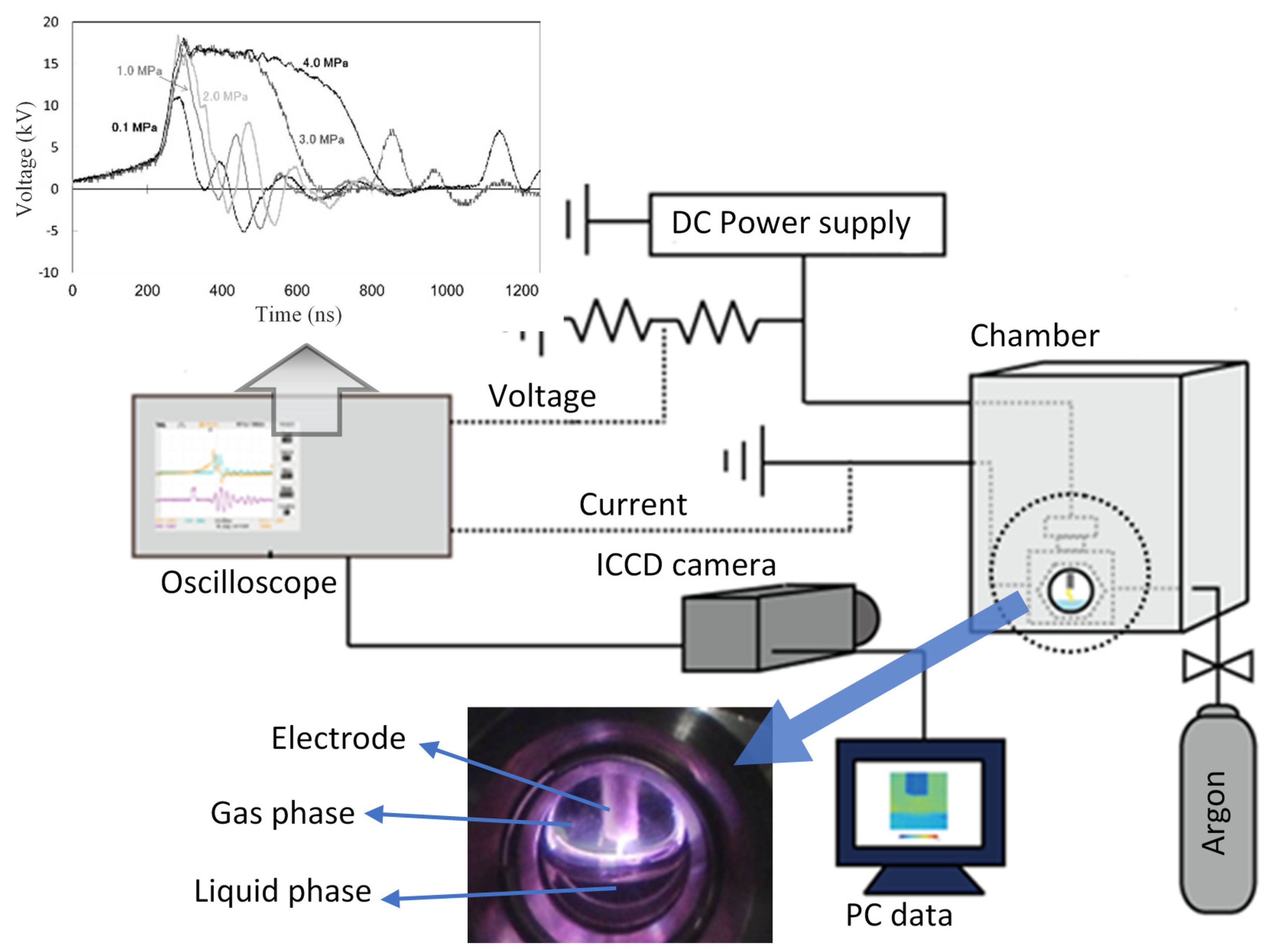
Figure 1. Experimental apparatus scheme.
Plasma 04 00021 g001
Figure 2. Typical arc plasma images (a,b) and their optical emission (c) intensities with copper as the electrode [38].
Plasma 04 00021 g002
Figure 3. Typical arc plasma images (a,b) and their optical emission intensities (c) with SUS as the electrode [38].
Plasma 04 00021 g003
Figure 4. OES of the pulsed discharge plasma that was applied to the liquid water surface.
Plasma 04 00021 g004
Figure 5. Decomposition of methyl orange dye as a water pollutant model compound [38].
Plasma 04 00021 g005
Figure 6. MALDI-TOF mass spectra of pyrrole after treatment using pulsed discharge plasma [37].
Plasma 04 00021 g006
Figure 7. Pyrrole oligomerization pathway [37].
Plasma 04 00021 g007
Figure 8. Solution products after the pulsed discharge plasma treatments: 0.1 (a), 1.0 (b), 1.5 (c), 2.0 (d), 3.0 (e), and 4.0 MPa (f), respectively [40].
Plasma 04 00021 g008
Figure 9. Raman spectrum of nanoparticle products formed by pulsed discharge plasma [40].
Plasma 04 00021 g009
Figure 10. TEM image of the nanoparticle products formed using pulsed discharge plasma (a) and their magnification (b) [40].
Plasma 04 00021 g010
Figure 11. SEM images of the carbon material products formed from various amino acid compounds, with their photographs in the insets [41].
Plasma 04 00021 g011
Figure 12. STEM image of titanium dioxide nanoparticles (a) with the corresponding EDS maps for titanium (b), oxygen (c), and carbon (d) elements [43].
Plasma 04 00021 g012
Figure 13. Raman spectrum of titanium dioxide nanoparticles formed using pulsed discharge plasma [43].
Plasma 04 00021 g013
Figure 14. HRTEM images of titanium dioxide (a) and carbon-titanium dioxide (b) [43].
Plasma 04 00021 g014
Publisher’s Note: MDPI stays neutral with regard to jurisdictional claims in published maps and institutional affiliations.