Article

Investigation of Plasma Propagation in Packed-Bed Dielectric Barrier Discharge Based on a Customized Particle-in-Cell/Monte Carlo Collision Model

1
Shanxi Center of Technology Innovation for Light Manipulations and Applications, School of Applied Science, Taiyuan University of Science and Technology, Taiyuan 030024, China
2
School of Physics, Dalian University of Technology, Dalian 116024, China
3
Modeling and Simulation Laboratory, Department of Physics, Government College University Faisalabad (GCUF), Allama Iqbal Road, Faisalabad 38040, Pakistan
4
Center of Plasma Nano-Interface Engineering, Kyushu University, Fukuoka 8190395, Japan
*
Authors to whom correspondence should be addressed.
These authors contributed equally to this work.
Plasma 2023, 6(4), 637-648; https://doi.org/10.3390/plasma6040044
Submission received: 15 August 2023 / Revised: 22 September 2023 / Accepted: 10 October 2023 / Published: 13 October 2023
(This article belongs to the Special Issue New Insights into Plasma Theory, Modeling and Predictive Simulations)

Abstract

:
This study investigates the propagation dynamics of plasma streamers in a packed-bed dielectric barrier discharge using a 2D particle-in-cell/Monte Carlo collision model. To accurately simulate the high-intensity discharge and streamer propagation mechanism at atmospheric pressure, additional algorithms for particle merging and a new electron mechanism are incorporated into the traditional particle-in-cell/Monte Carlo collision model. To validate the accuracy of this improved model, qualitative comparisons are made with experimental measurements from the existing literature. The results show that the speed of streamer propagation and the distribution of plasma are strongly influenced by the dielectric constant of the packed pellet, which is commonly used as a catalyst. In cases with a moderate dielectric constant, the presence of a strong electric field between the pellet and dielectric layer on the electrode significantly enhances the discharge. This enables the streamer to propagate swiftly along the pellet surface and results in a wider spread of plasma. Conversely, a very high dielectric constant impedes streamer propagation and leads to localized discharge with high intensity. The improved model algorithms derived from this research offer valuable insights for simulating high-density plasma discharge and optimizing plasma processing applications.

1. Introduction

Low-temperature plasmas are commonly associated with the generation of abundant reactive species, such as radicals, excited atoms, and ions. These species exhibit a high level of reactivity and significantly contribute to the initiation and progression of chemical reactions [1]. Dielectric barrier discharge (DBD) has gained significant attention as a promising plasma technology for various applications due to its non-thermal and efficient generation of reactive species [2,3,4,5]. DBD systems consist of electrodes separated by dielectric barriers, with a working gas introduced into the discharge region. The volume between the electrodes is often filled with dielectric pellets/beads loaded with a catalyst, which is also referred to as packed-bed DBD [6,7,8]. Many types of catalytic materials and shapes can be applied, including spheres, foams, and honeycombs, to enhance reactivity and selectivity [9,10]. The discharge occurring in the catalyst gap within the DBD reactor generates plasma species that facilitate a specific chemical reaction process. A comprehensive understanding of the dynamics of plasma propagation in DBD is essential in order to optimize system performance for applications involving gas flow control, gas purification, material processing, biomedical applications, and plasma–catalyst interactions [11,12,13,14,15,16].
There are two types of streamers that can be stimulated in a dielectric barrier discharge (DBD): negative and positive streamers [17]. Negative streamers propagate in the direction of the electron drift in the applied electric field, while positive streamers move against the drift direction. Therefore, positive streamers require a source of electrons in front of the streamer head. This source is commonly attributed to photoionization [18,19,20,21,22]. As a result of distinct production processes, there are significant variations in the propagation properties and interactions of positive and negative streamers with catalyst materials. Consequently, they require distinct treatment approaches in the simulation. Additionally, the interaction between the catalyst pellet and the streamers is a complex and crucial process. Firstly, the geometry and dielectric constant of the catalyst pellets influence the local electric field, which, in turn, affects the formation and propagation of the plasma. Secondly, the distribution of plasma plays a crucial role in determining the contact area between charged particles or active groups and the catalyst, thereby influencing the overall catalytic performance. This intricate relationship highlights the significance of understanding and studying the interaction between catalyst pellets and streamers.
Previous studies have reported that catalyst beads with sharp edges, small sizes, and high dielectric constants can enhance decomposition efficiency and conversion rates [23,24,25]. In order to investigate the underlying causes, Kim et al. utilized ICCD imaging to analyze the discharge phenomena of a packed-bed dielectric barrier discharge (DBD). They identified two types of discharge: streamer-like surface discharges and local microdischarge between the packing beads [26,27]. Tu et al. conducted experiments and observed a transition from the typical filamentary discharge to a combination of local microdischarges and predominant surface discharges in a packed-bed reactor filled with Ni/Al2O3 [28]. Similarly, Butterworth and Allen experimentally observed two main types of discharge in a single-catalyst-pellet DBD reactor using nitrogen: point-to-point local microdischarges and surface streamers; these were found to be influenced by the material’s dielectric constant [29]. Wang et al., furthermore, examined streamer propagation and discharge characteristics in a packed-bed DBD reactor using ICCD [30]. They concluded that, in addition to the discharge mode transition, a higher dielectric constant constrains the discharge to the contact points of the beads, resulting in enhanced intensity. The production of reactive species is most prominent in the positive restrikes, surface discharges, and local microdischarges occurring between the beads. Electrons emitted by the electric field serve as a pre-ionization source and additional electron sources, which subsequently amplify the partial discharge.
The aforementioned studies, while intriguing, face challenges in directly observing microscopic plasma processes due to limited resolution during experiments. Therefore, the development of models becomes crucial. Notably, the particle-in-cell/Monte Carlo collision (PIC/MCC) model stands out as it enables the self-consistent simulation of electron and ion dynamics, electric field calculations, and collision processes within a dielectric barrier discharge (DBD) system [31,32,33,34]. Y Zhang et al. used the PIC/MCC model to study the discharge process of a pulsed streamer in a small-sized packed-bed DBD [35]. They compared the results with computational outcomes from a fluid model. The findings indicated that the electron avalanche process, electron density, and average propagation velocity in the PIC/MCC model were similar to the values reported in the literature [36], meanwhile the simulated density profile achieved qualitative agreement with the experimental observations at a low dielectric constant in [30] (i.e., surface discharges predominantly occurred along the gaps between the pellets), thus validating the accuracy of the PIC/MCC model in simulating the discharge process in packed-bed DBD systems.
J Kuhfeld et al. utilized the PIC/MCC model to study the physical characteristics of nanosecond-pulsed microplasma discharges, achieving excellent agreement with experimental measurements [37]. Hong et al. [38] successfully conducted PIC simulations and fluid simulations of helium microdischarges at atmospheric pressure. Within a specific radio frequency range, the simulation results from both models exhibit good consistency. However, streamer discharge exhibits an extremely intense nature, characterized by a rapid increase in electron density over time. Additionally, positive streamers demand a consistent influx of electrons to be continuously replenished ahead of the streamer head, taking into account photoionization and cosmic radiation electrons. These challenges significantly impact the stability of conventional PIC models, thereby demanding the implementation of specialized optimizations for the PIC model.
In this study, we will construct and implement a customized PIC/MCC model (with algorithms similar to those used in the model presented in [35]) specifically adapted to simulate plasma dynamics in atmospheric discharges. The model will account for various parameters such as electrode configuration, dielectric barrier structure, gas composition, and applied voltage waveform. By accurately reproducing these parameters, the model will offer valuable insights into plasma propagation phenomena observed in DBD systems. To enhance credibility, partial results of the model are qualitatively validated by experimental observations reported in the existing literature.

2. Computational Model

Figure 1a illustrates the 2D model structure of the rectangular-surface dielectric barrier discharge reactor utilized in this study, with inner dimensions measuring 5.6 mm × 11 mm. The upper and lower electrodes are coated with a dielectric layer, which has a thickness of 0.4 mm. The separation between these two planar dielectrics is set at 4 mm. Additionally, a hemispherical dielectric pellet, with a radius of 6 mm and a height of 2.4 mm, is incorporated into the lower electrode. The dielectric layer possesses a relative permittivity of 4. In practice, the dielectric constant range of catalytic media and filler pellets in packed-bed DBD systems is quite extensive. It typically includes materials such as zeolites ( ε r = 1.5–5), silica ( ε r = 4.2), metal oxides (e.g., Al2O3 ( ε r = 1.5–5), CeO2 ( ε r ≈ 24)), semiconductor materials (e.g., WO3 ( ε r = 10–20), and TiO2 ( ε r = 40–100)), and ferroelectric materials (e.g., CaTiO3 ( ε r ≈ 200), SrTiO3 ( ε r ≈ 300), and BaTiO3 ( ε r ≈ 10,000)). The simulated discharge geometry is divided into square cells, with each cell having dimensions of 11 μm × 11.2 μm, resulting in a grid consisting of 1000 × 500 cells. For the majority of the simulated geometry, the plasma density is relatively low and the spatial step length is smaller than the Debye length. However, in the bulk region of the plasma streamer, although the electron density is high, both the spatial charge separation and the electric field are weak. As a result, even if the spatial step length is greater than the Debye length in the bulk streamer region, it does not have a significant impact on the numerical accuracy (especially in such a short discharge time ~ns).
In order to mirror the simulated region and ensure smooth and adaptive potential on the simulated wall, Neumann boundary conditions are applied to both the left and right boundaries. A non-adaptive time steps is employed in the simulation, which is fixed at 2 × 10⁻¹³ s. In this setup, the upper electrode is subjected to a DC voltage of 16 kV, while the lower electrode is maintained at ground potential.
Figure 1b depicts the utilization of a 2D PIC/MCC model, implemented within the VSim simulation software, to investigate the progression of the plasma streamer. Differing from fluid models that employ drift–diffusion approximations to solve the transport equation for charged particles, the PIC method operates on first principles. It directly computes the electromagnetic field distribution to propel particles and subsequently employs statistical techniques to calculate the corresponding physical quantities. Specifically, we employ an electrostatic model, namely Poisson’s equation (Equation (1)), to calculate the electric potential and electric field at the position of a particle.
2 ϕ = 4 π q δ r r j   ,
E = ϕ   .
where ϕ represents the electric potential, r j is the coordinate of the j -th particle, q is the charge carried by the particle, and E represents the electric field.
Due to the inclusion of dielectric materials in the model, it is necessary to consider polarization effects. The Poisson equation in Equation (1) is modified as follows:
D = 4 π q δ r r j   ,
ε φ = 4 π q δ r r j   ,
In the provided equation, D represents the electric displacement vector, ε is the permittivity ( ε = ε 0 ε r ), and ε 0   is the dielectric constant of vacuum. Given the inclusion of dielectric material in the model, the relative permittivity ε r is a spatially varying function, denoted as ε r (r), and cannot be moved outside the divergence operator. This process implements the “Poisson solver” in Figure 1b.
The fore on a particle i due to all other particles is given by
F i = q i j , i j E i j
Next, we employ Newton’s second law to calculate the velocity of each particle and the particle’s displacement during each time step, obtaining the coordinates and velocities of the particles at the next time step. This process implements the “Particle Pusher” technique in Figure 1b. Given the large number of physical particles involved in the simulation, it is impractical to compute their motion individually. In the PIC model, a large number of particles with very close positions in the phase space, defined by their coordinates and velocities, are merged into a single “superparticle.” It is assumed that all physical particles within a superparticle undergo identical motion in the phase space. This simplification reduces the computation of the motion of all physical particles to a manageable number of superparticles. The more superparticles are utilized, the more precise the simulation results, but this comes at the cost of increased computational resources. Therefore, a balance must be struck between accuracy and computational efficiency.
During the development of plasma streamers, the number of particles in each species undergoes rapid growth as a consequence of ionization avalanches. To address this and improve computational efficiency, an adaptive approach is used to adjust the weight of each superparticle. A merger algorithm is implemented to ensure conservation of both momentum and energy. This algorithm combines superparticles of the same species when the number of superparticles in each cell of the simulation mesh exceeds a predefined threshold of 10. Specifically, four particles within the same cell are randomly selected and combined into two particles, following Equations (6) and (7).
m 1 v 1 α + m 2 v 2 α + m 3 v 3 α + m 4 v 4 α = m A v A α + m B v B α
m 1 v 1 α 2 + m 2 v 2 α 2 + m 3 v 3 α 2 + m 4 v 4 α 2 = m A v A α 2 + m B v B α 2
where m 1 ,   m 2 ,   m 3 ,   m 4 represent the masses of the particles before merging, and v 1 α ,   v 2 α ,   v 3 α , v 4 α are the components of the velocities of the particles before merging in the α direction. m A and m B denote the masses of the particles after merging, while v A α and v B α represent the components of the velocities of the particles after merging in the α direction.
This process corresponds to the “Particle merger” in Figure 1b. The particle merger must be in effect throughout the calculation to constantly keep the local required accuracy.
v A , B α = M α ± E α M α 2 m A + m B
In Equation (8), M α is the total momentum (in the direction α ) and E α the total energy in the direction α . m A and   m B are derived using the conservation of grid moments. From Equation (8), we can determine the velocity components in the α direction for particle A and particle B after their merger. During this process, it is ensured that the velocity distribution of the particles remains unchanged, and their contributions to the grid moments are equal, thereby preserving the effectiveness of the computational results.
Detailed information regarding this adaptive weight and ‘particle merger’ algorithm can be found in references [34,39]. The merger algorithm plays a crucial role in simulating the evolution of the streamer by effectively limiting the total particle number and stabilizing the model. Without this algorithm, the model would rapidly break down due to the exponential increase in particle number during intense streamer discharges.
When simulating processes like plasma discharge, it is often necessary to couple the MCC method to account for short-range interactions between particles, i.e., the collision process. The discharge is conducted under atmospheric pressure using various gas mixtures consisting of oxygen (O2) and nitrogen (N2), with a consistent gas temperature of 300 K and an oxygen ratio of 50%. Throughout the simulation, free electrons, as well as N2+, O2+, and O2 ions, are meticulously tracked and represented as superparticles. The electron impact reaction mechanisms considered in the simulation include elastic collisions, as well as collisions involving attachment, excitation, and ionization with N2 and O2 gas molecules. This process corresponds to the “MC Collisions” in Figure 1b. These mechanisms are further elaborated in references [34,39]. The cross-sections and threshold energies utilized in the simulation are derived from the LXCat database and other relevant literature sources [40,41,42,43,44]. Particles such as metastable and free radicals are not directly considered. However, the MCC model indirectly accounts for their influence through electron impact reactions, which determines power deposition and electron energy.
To simulate the initiation of the plasma discharge, a uniform distribution of seed electrons with a density of 1 × 10¹⁵ m−3 is introduced into the unoccupied space within the simulated geometry. In reality, seed electrons exist naturally as a result of cosmic radiation and environmental photo-ionization. These processes contribute to the generation of background electrons and the sustained presence of charges from previous plasma discharges. Following a similar approach to that in [39,45], during each time-step, a single new electron superparticle is randomly introduced into the simulation domain at various positions. This process corresponds to the “new electron addition” in Figure 1b, which is crucial in simulating positive streamers because initially arranged electrons move in the opposite direction due to the applied electric field and induced electric field in the streamer head. These electrons are quickly depleted during the simulation, causing the simulated streamer to stop. However, in reality, there exists a continuous source of electrons in front of the streamer head, which sustains the evolution of the positive streamer. The ‘new electron addition’ allows for the consideration of random events, such as cosmic radiation, photo-ionization, and various secondary electron emission (SEE) processes, detailed in [19,21,46]. Noting this, the ‘particle merger’ and ‘new electron addition’ steps are newly introduced mechanisms in the traditional PIC/MCC flow, and are of significance to simulate high-density discharge in restricted geometry.
After the “new electron addition”, all superparticles acquire new coordinate positions and proceed to the next step. For each charged particle, its charge is then distributed onto discretized grid points with specific weights to obtain the charge density distribution, i.e., the “particle weighting” step in Figure 1b. Subsequently, in the next time step, the Poisson equation is solved using the computed charge density distribution. This iterative process is repeated to simulate the entire discharge evolution process.

3. Results and Discussion

3.1. Plasma Streamer Evolution in Packed-Bed DBD

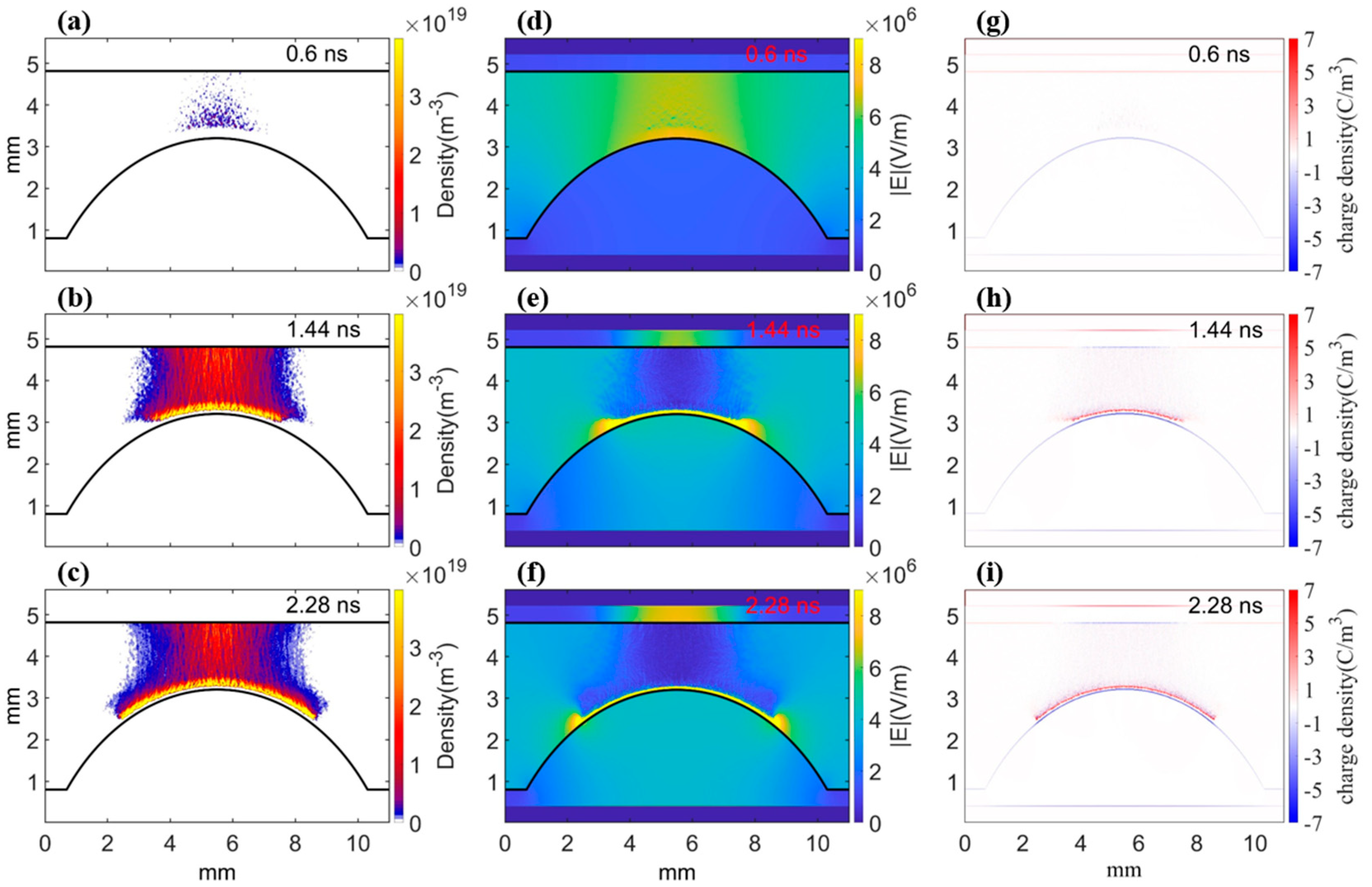
Figure 2 showcases the electron density profiles, electric field distributions, and charge density distributions (including the space charge density, surface charge density on the dielectric surface, and polarization charge inside the dielectric) in the discharge gap at three specific time points, shedding light on the dynamic evolution of a plasma streamer. Notably, the polarization effect of the pellet will enhance the potential drop between the pellet and top electrode, and the top of the pellet exhibits a prominent geometric curvature, which distorts the potential in that region. This arrangement yields a robust electric field above the pellet (Figure 2d), facilitating the initiation of numerous separate avalanches and the formation of individual streamers. As a result, a plasma streamer starts to develop gradually from the cascade of particle seeds after 0.6 ns (Figure 2a). As time progresses, the plasma streamer undergoes further development and gains strength, eventually reaching the top of the pellet and transforming into a surface streamer. As shown in Figure 2h, positive charges (red color) accumulate above the surface of the dielectric pellet. And on the surface of the dielectric near the positively charged streamer head, a strong polarization charge (blue color) is generated, inducing a strong electric field between the streamer head and pellet, as shown in Figure 2e. Additionally, it continues to propagate downward along the surface of the pellet in both the left and right directions. A small gap can be observed between the primary streamer and the pellet, which signifies a notable physical phenomenon known as a floating positive surface streamer. This surface streamer possesses a notably high density, resulting in the induction of a strong electric field within the gap between the streamer and the pellet surface. Additionally, the electric field is the most intense in the streamer heads, where significant charge separation occurs, see Figure 2i, thus facilitating the continuous development of the streamer. By comparing Figure 2d,f, it can be inferred that the induced electric field in the streamer head is stronger than the applied electric field. This suggests that the streamer is predominantly governed by the induced electric field within its own streamer head once it is formed.
Moreover, it is important to note that the observed plasma diameter in our simulation may appear to be larger than in the experimental observations. This can be attributed to several factors. Firstly, the simulated streamer is presented using a wide color range. Regions represented in blue and faint red indicate very low density that falls below the detection capabilities of experiments. Secondly, in order to reduce the computational burden of the PIC/MCC model, we employed a relatively small simulation domain with a high driving voltage to accelerate the evolution of the streamer. This can result in significantly stronger electric fields in the discharge region compared to practical electric fields in experiments, leading to a streamer with higher electron density, faster propagation, and a larger diameter. Nonetheless, the fundamental physical mechanisms and dynamics of streamer propagation remain unchanged, which are the primary focus of this study. Furthermore, variations in the discharge gases can also influence the mean free paths of electrons, with a larger mean free path corresponding to a wider plasma width.

3.2. Effect of Pellet Material on Plasma Streamer Propagation

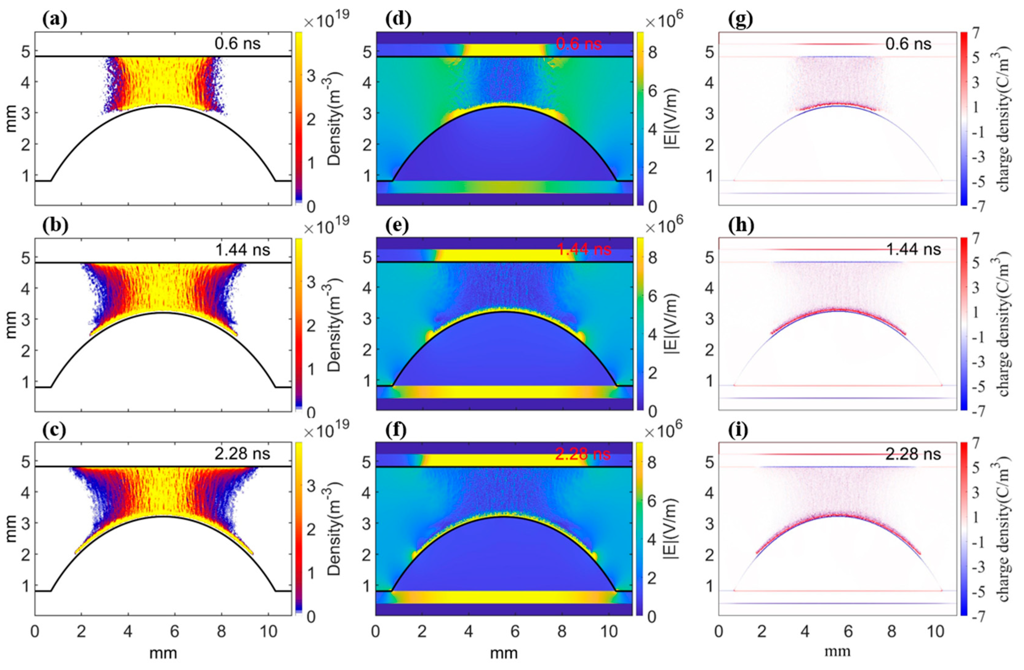
In this subsection, we further explore the impact of the dielectric constant on the evolution of the plasma streamer by adjusting the material of the pellet. Figure 3 presents the temporal evolution of the electron density, electric field, and charge density distributions, assuming a dielectric constant of the pellet equal to 40. In comparison to the circumstances depicted in Figure 2 (where the dielectric constant is 4), the streamer develops significantly faster and exhibits a more intense discharge before reaching the top of the pellet. This can be attributed to the higher dielectric constant (40), which facilitates polarization of the dielectric material. Consequently, the potential drop inside the pellet is reduced, while the potential drop and electric field above the pellet are much enhanced. This leads to an accelerated cascading of particle seeds and evolution of the streamer above the pellet, with a more intense density. The streamer continues to develop along the surface of the pellet once it reaches it in both the left and right directions, but at a slightly higher speed due to the stronger discharge compared to Figure 2. Furthermore, upon comparing the charge density plots in Figure 2, it becomes evident that the positive streamer exhibits a higher positive charge density at a higher dielectric constant of 40. Simultaneously, the polarization-induced negative charge density on the dielectric surface also becomes more pronounced (as seen in Figure 3g–i). However, it is worth highlighting the presence of another surface streamer along the top dielectric layer. Unlike the previous streamer, this one is in direct contact with the top dielectric layer (i.e., no distance gap between the streamer and dielectric), indicating stimulation of the negative surface streamer [17]. The negative surface streamer is induced by the surface charging on the top dielectric layer caused by the strong primary discharge in the gas phase. This generates an additional electric field along the dielectric layer surface, which maintains the negative surface streamer [17]. As a result, the plasma distribution profile, the electric field distribution profile, and the streamer propagation dynamics show clear differences when the pellet constant is increased, as demonstrated in Figure 2c,f and Figure 3c,f. With a moderate dielectric constant of 40, the streamer propagates along both the pellet surface and the electrode layer surface. This enables the plasma to expand into a significantly larger area, which positively impacts the processing performance.
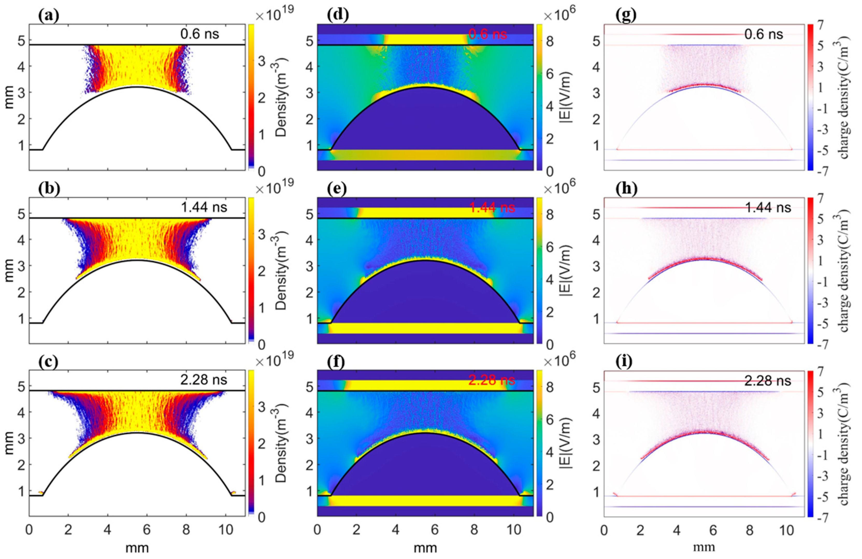
We further illustrate the temporal evolution of electron density, electric field, and charge density distributions in Figure 4, considering a dielectric constant of 400 for the pellet material. With a higher dielectric constant, the polarization effect becomes extremely strong, leading to a more enhanced electric field above the pellet and more rapid development of the streamer before reaching the pellet. Furthermore, we observed a significantly intensified discharge occurring between the pellet and the top dielectric layer. This discharge is characterized by pronounced positive charge density in the streamer head and the presence of negative charge density induced by polarization on the dielectric surface, as shown in Figure 4g–i. However, the subsequent positive surface streamer along the pellet experiences slightly slower progression, which can be inferred by comparing Figure 3c and Figure 4c. This phenomenon is also influenced by the polarization effect of the pellet. The polarization resulting from a very high dielectric constant (~400) causes a substantial accumulation of polarization charge (blur color) on the surface of the pellet. This, in turn, leads to an increase in the potential drop above the pellet, while decreasing the potential drop inside the pellet and along its surface. Consequently, the electric field between the floating positive surface streamer and the dielectric is intensified, while the electric field inside the pellet and along the pellet surface is weakened. This ultimately restrains the propagation of the streamer along the pellet surface (i.e., reducing the speed of the streamer). These observations are consistent with the experimental measurements in [30]. In their experiment, they explored discharge phenomena in a packed-bed DBD reactor filled with pellet materials with dielectric constants ranging from 5 to 1000. Their observations revealed that at lower dielectric constants ( ε r   = 5), surface discharges predominantly occurred along the gaps between the pellets, while at higher dielectric constants ( ε r   = 1000), filamentary micro-discharges were observed between the pellets, representing localized discharges. In other words, the discharge is significantly enhanced and localized at contact points within packed-bed DBD systems using pellets with high dielectric constants. The outcomes qualitatively validate the accuracy of the employed PIC/MCC model.
On the other hand, the negative surface streamer develops faster along the top layer compared to Figure 3. This can be attributed to the more intense gas-phase discharge, which enhances the surface charging on the layer, leading to a stronger negative streamer (noting that the dielectric constant is fixed at 4).
Therefore, a moderate dielectric constant (~40) promotes streamer propagation along the pellet. However, a significantly higher dielectric constant (~400) hinders the streamer propagation and leads to localized discharge with intense discharge. These observations highlight the significant impact of dielectric constant on the spatio-temporal behavior of plasma density and the electric field during the discharge process. By arranging catalyst pellets with different dielectric constants in a reasonable manner in a packed-bed DBD, it might be possible to manipulate the streamer propagation, discharge intensity, and plasma distribution as needed, ultimately enhancing the overall catalytic performance.

4. Conclusions

In conclusion, this study investigated the evolution of a plasma streamer in a packed-bed dielectric barrier discharge reactor with a single catalyst pellet, based on a customized PIC/MCC Model. The ‘particle merger’ and ‘new electron addition’ mechanisms were employed for the PIC/MCC flow, which are of significance in simulating high-density discharge and positive streamer propagation in restricted geometry.
The effects of the dielectric constant of the pellet material on the propagation of the streamer were thoroughly examined. The results showed that a gas-phase streamer and positive and negative streamers can be simulated in the same reactor. A moderate dielectric constant of the pellet (~40) has multiple effects on streamer development and discharge in the gas phase. It accelerates the streamer’s progression and increases plasma density in the gas-phase discharge before reaching the pellet. Additionally, it facilitates the propagation of positive surface streamers along the pellet and generates an additional negative surface streamer along the electrode layer, allowing the plasma to spread into large area. On the other hand, a very high dielectric constant (~400) strongly polarizes the pellet, resulting in an intensified electric field above the pellet and a weakened electric field inside and along the pellet. As a result, positive surface streamer propagation along the pellet is impeded, leading to localized discharge with high intensity. Conversely, the negative surface streamer experiences faster development along the top layer due to enhanced gas-phase discharge and increased surface charging. The results of this study demonstrate the significant impact of dielectric constant on the spatio-temporal behavior of plasma density and the electric field during the discharge process. These findings can be effectively leveraged to improve the overall processing performance of packed-bed DBD systems by arranging catalyst pellets with diverse dielectric constants in a rational manner. It can be inferred that strategically arranging dielectric particles with different dielectric constants, such as placing small catalyst pellets with high dielectric constants in the gaps between larger pellets with low dielectric constants, may allow for the manipulation of discharge with a large profile and the occurrence of localized intensified discharge. This arrangement may contribute to enhanced catalytic efficiency.

Author Contributions

Conceptualization, X.L. and Q.Z.; methodology, L.Z.; software, L.Z.; validation, X.L., L.Z. and Q.Z.; formal analysis, A.S. and P.A.; investigation, X.L., L.Z. and Q.Z.; resources, A.S. and P.A.; writing—original draft preparation, X.L., L.Z. and Q.Z.; writing—review and editing, A.S., P.A. and Q.Z.; visualization, Q.Z.; supervision, X.L. and Q.Z.; project administration, X.L. and Q.Z.; funding acquisition, X.L. and Q.Z. All authors have read and agreed to the published version of the manuscript.

Funding

This research was funded by the National Natural Science Foundation of China (NSFC), grant number 12105035; the Guangdong Basic and Applied Basic Research Foundation, grant number 2021B1515120018; and the Shanxi “1331 Project” Key Innovative Research Team, grant number 1331KIRT.

Institutional Review Board Statement

Not applicable.

Informed Consent Statement

Not applicable.

Data Availability Statement

The data that support the findings of this study are available from the corresponding author upon reasonable request.

Conflicts of Interest

The authors declare no conflict of interest.

References

  1. Adamovich, I.; Baalrud, S.D.; Bogaerts, A.; Bruggeman, P.J.; Cappelli, M.; Colombo, V.; Czarnetzki, U.; Ebert, U.; Eden, J.G.; Favia, P.; et al. The 2017 Plasma Roadmap: Low temperature plasma science and technology. J. Phys. D Appl. Phys. 2017, 50, 323011. [Google Scholar] [CrossRef]
  2. Bogaerts, A.; Neyts, E.C. Plasma Technology: An Emerging Technology for Energy Storage. ACS Energy Lett. 2018, 3, 1013. [Google Scholar] [CrossRef]
  3. Snoeckx, R.; Bogaerts, A. Plasma technology—A novel solution for CO2 conversion? Chem. Soc. Rev. 2017, 46, 5805. [Google Scholar] [CrossRef] [PubMed]
  4. Patil, B.S.; Cherkasov, N.; Lang, J.; Ibhadon, A.O.; Hessel, V.; Wang, Q. Low temperature plasma-catalytic NOx synthesis in a packed DBD reactor: Effect of support materials and supported active metal oxides. Appl. Catal. B 2016, 194, 123–133. [Google Scholar] [CrossRef]
  5. Neyts, E.C.; Bogaerts, A. Understanding plasma catalysis through modelling and simulation—A review. J. Phys. D Appl. Phys. 2014, 47, 224010. [Google Scholar] [CrossRef]
  6. Chen, H.L.; Lee, H.M.; Chen, S.H.; Chao, Y.; Chang, M.B. Review of plasma catalysis on hydrocarbon reforming for hydrogen production—Interaction, integration, and prospects. Appl. Catal. B Environ. 2008, 85, 1–9. [Google Scholar] [CrossRef]
  7. Van Laer, K.; Bogaerts, A. Fluid modelling of a packed bed dielectric barrier discharge plasma reactor. Plasma Sources Sci. Technol. 2016, 25, 015002. [Google Scholar] [CrossRef]
  8. Van Laer, K.; Bogaerts, A. How bead size and dielectric constant affect the plasma behaviour in a packed bed plasma reactor: A modelling study. Plasma Sources Sci. Technol. 2017, 26, 085007. [Google Scholar] [CrossRef]
  9. Hensel, K.; Sato, S.; Mizuno, A. Electrical discharge in honeycomb monolith. Chem. Listy 2008, 102, S1318–S1321. [Google Scholar]
  10. Kirkpatrick, M.J.; Odic, E.; Leininger, J.P.; Blanchard, G.; Rousseau, S.; Glipa, X. Plasma assisted heterogeneous catalytic oxidation of carbon monoxide and unburned hydrocarbons: Laboratory-scale investigations. Appl. Catal. B 2011, 106, 160–166. [Google Scholar] [CrossRef]
  11. Brandenburg, R. Dielectric barrier discharges: Progress on plasma sources and on the understanding of regimes and single filaments. Plasma Sources Sci. Technol. 2017, 26, 053001. [Google Scholar] [CrossRef]
  12. Kim, H.H. Nonthermal Plasma Processing for Air-Pollution Control: A Historical Review, Current Issues, and Future Prospects. Plasma Process. Polym. 2004, 1, 91–110. [Google Scholar] [CrossRef]
  13. Neyts, E.C.; Ostrikov, K.; Sunkara, M.K.; Bogaerts, A. Plasma Catalysis: Synergistic Effects at the Nanoscale. Chem. Rev. 2015, 115, 13408. [Google Scholar] [CrossRef] [PubMed]
  14. Kim, H.H.; Ogata, A.; Futamura, S. Oxygen partial pressure-dependent behavior of various catalysts for the total oxidation of VOCs using cycled system of adsorption and oxygen plasma. Appl. Catal. B. 2008, 79, 356. [Google Scholar] [CrossRef]
  15. Van Durme, J.; Dewulf, J.; Leys, C.; Van Langenhove, H. Combining non-thermal plasma with heterogeneous catalysis in waste gas treatment: A review. Appl. Catal. B. 2008, 78, 324. [Google Scholar] [CrossRef]
  16. Whitehead, J.C. Plasma–catalysis: The known knowns, the known unknowns and the unknown unknowns. J. Phys. D Appl. Phys. 2016, 49, 243001. [Google Scholar] [CrossRef]
  17. Zhang, Q.; Zhang, L.; Yang, D.; Schulze, J.; Wang, Y.; Bogaerts, A. Positive and negative streamer propagation in volume dielectric barrier discharges with planar and porous electrodes. Plasma Process. Polym. 2021, 18, e2000234. [Google Scholar] [CrossRef]
  18. Nijdam, S.; van de Wetering, F.M.J.H.; Blanc, R.; van Veldhuizen, E.M.; Ebert, U. Probing photo-ionization: Experiments on positive streamers in pure gases and mixtures. J. Phys. D Appl. Phys. 2010, 43, 145204. [Google Scholar] [CrossRef]
  19. Ebert, U.; Montijn, C.; Briels, T.M.P.; Hundsdorfer, W.; Meulenbroek, B.; Rocco, A.; van Veldhuizen, E.M. The multiscale nature of streamers. Plasma Sources Sci. Technol. 2006, 15, S118. [Google Scholar] [CrossRef]
  20. Ningyu, L.; Victor, P.P. Effects of photoionization on propagation and branching of positive and negative streamers in sprites. J. Geophys. Res. Sp. Phys. 2004, 109, A 04301. [Google Scholar]
  21. van Veldhuizen, E.M.; Rutgers, W.R. Pulsed positive corona streamer propagation and branching. J. Phys. D Appl. Phys. 2002, 35, 2169. [Google Scholar] [CrossRef]
  22. Nijdam, S.; Takahashi, E.; Markosyan, A.H.; Ebert, U. Investigation of positive streamers by double-pulse experiments, effects of repetition rate and gas mixture. Plasma Sources Sci. Technol. 2014, 23, 25008. [Google Scholar] [CrossRef]
  23. Chen, H.L.; Lee, H.M.; Chen, S.H.; Chang, M.B. Review of Packed-Bed Plasma Reactor for Ozone Generation and Air Pollution Control. Ind. Eng. Chem. Res. 2008, 47, 2122–2130. [Google Scholar] [CrossRef]
  24. Butterworth, T.; Elder, R.; Allen, R. Effects of particle size on CO2 reduction and discharge characteristics in a packed bed plasma reactor. Chem. Eng. J. 2016, 293, 55–67. [Google Scholar] [CrossRef]
  25. Uytdenhouwen, Y.; Van Alphen, S.; Michielsen, I.; Meynen, V.; Cool, P.; Bogaerts, A. A packed-bed DBD micro plasma reactor for CO2 dissociation: Does size matter? Chem. Eng. J. 2018, 348, 557–568. [Google Scholar] [CrossRef]
  26. Kim, H.H.; Teramoto, Y.; Negishi, N.; Ogata, A. A multidisciplinary approach to understand the interactions of nonthermal plasma and catalyst: A review. Catal. Today 2015, 256, 13–22. [Google Scholar] [CrossRef]
  27. Kim, H.H.; Teramoto, Y.; Sano, T.; Negishi, N.; Ogata, A. Effects of Si/Al ratio on the interaction of nonthermal plasma and Ag/HY catalysts. Appl. Catal. B Environ. 2015, 166, 9–17. [Google Scholar] [CrossRef]
  28. Tu, X.; Gallon, H.J.; Twigg, M.V.; Gorry, P.A.; Whitehead, J.C. Dry reforming of methane over a Ni/Al2O3 catalyst in a coaxial dielectric barrier discharge reactor. J. Phys. D Appl. Phys. 2011, 44, 274007. [Google Scholar] [CrossRef]
  29. Butterworth, T.; Allen, R.W.K. Plasma-catalyst interaction studied in a single pellet DBD reactor: Dielectric constant effect on plasma dynamics. Plasma Sources Sci. Technol. 2017, 26, 065008. [Google Scholar] [CrossRef]
  30. Wang, W.; Kim, H.-H.; Van Laer, K.; Bogaerts, A. Streamer propagation in a packed bed plasma reactor for plasma catalysis applications. Chem. Eng. J. 2018, 334, 2467–2479. [Google Scholar] [CrossRef]
  31. Zhang, Q.Z.; Bogaerts, A. Plasma streamer propagation in structured catalysts. Plasma Sources Sci. Technol. 2018, 27, 105013. [Google Scholar] [CrossRef]
  32. Zhang, Q.-Z.; Wang, W.-Z.; Bogaerts, A. Importance of surface charging during plasma streamer propagation in catalyst pores. Plasma Sources Sci. Technol. 2018, 27, 065009. [Google Scholar] [CrossRef]
  33. Zhang, Q.Z.; Bogaerts, A. Propagation of a plasma streamer in catalyst pores. Plasma Sources Sci. Technol. 2018, 27, 035009. [Google Scholar] [CrossRef]
  34. Zhang, Y.; Wang, H.Y.; Zhang, Y.R.; Bogaerts, A. Formation of microdischarges inside a mesoporous catalyst in dielectric barrier discharge plasmas. Plasma Sources Sci. Technol. 2017, 26, 054002. [Google Scholar] [CrossRef]
  35. Zhang, Y.; Wang, H.-Y.; Jiang, W.; Bogaerts, A. Two-dimensional particle-in cell/Monte Carlo simulations of a packed-bed dielectric barrier discharge in air at atmospheric pressure. New J. Phys. 2015, 17, 083056. [Google Scholar] [CrossRef]
  36. Nieter, C.; Cary, J.R. VORPAL: A versatile plasma simulation code. J. Comput. Phys. 2004, 196, 448–473. [Google Scholar] [CrossRef]
  37. Kuhfeld, J.; Lepikhin, N.D.; Luggenhölscher, D.; Czarnetzki, U.; Donkó, Z. PIC/MCC simulation for a ns-pulsed glow discharge in nitrogen at sub-atmospheric pressure and analysis of its quasi-steady state physics. Plasma Sources Sci. Technol. 2023, 32, 084001. [Google Scholar] [CrossRef]
  38. Hong, Y.J.; Yoon, M.; Iza, F.; Kim, G.C.; Lee, J.K. Comparison of fluid and particle-in-cell simulations on atmospheric pressure helium microdischarges. J. Phys. D Appl. Phys. 2008, 41, 245208. [Google Scholar] [CrossRef]
  39. Zhang, Q.-Z.; Nguyen-Smith, R.T.; Beckfeld, F.; Liu, Y.; Mussenbrock, T.; Awakowicz, P.; Schulze, J. Computational study of simultaneous positive and negative streamer propagation in a twin surface dielectric barrier discharge via 2D PIC simulations. Plasma Sources Sci. Technol. 2021, 30, 075017. [Google Scholar] [CrossRef]
  40. Lichtenberg, A.J.; Lieberman, M.A. Principles of Plasma Discharges and Materials Processing, 2nd ed.; Wiley: New York, NY, USA, 2005. [Google Scholar]
  41. Furman, M.A.; Pivi, M.T.F. Probabilistic model for the simulation of secondary electron emission. Phys. Rev. Spec. Top. Accel. Beams 2002, 5, 124404. [Google Scholar] [CrossRef]
  42. Phelps, A.V.; Petrovic, Z.L. Cold-cathode discharges and breakdown in argon: Surface and gas phase production of secondary electrons. Plasma Sources Sci. Technol. 1999, 8, R21. [Google Scholar] [CrossRef]
  43. Pancheshnyi, S.; Biagi, S.; Bordage, M.C.; Hagelaar, G.J.M.; Morgan, W.L.; Phelps, A.V.; Pitchford, L.C. The LXCat project: Electron scattering cross sections and swarm parameters for low temperature plasma modeling. Chem. Phys. 2012, 398, 148–153. [Google Scholar] [CrossRef]
  44. Biagi v8.9 Database. 2015. Available online: www.lxcat.net (accessed on 2 November 2021).
  45. Alexandre, L.; Mikhail, S.; Dmitry, O.; Richard, M.; Sergey, M. Limitations of the DBD effects on the external flow. In Proceedings of the 48th AIAA Aerospace Sciences Meeting including the New Horizons Forum and Aerospace Exposition, Orlando, FL, USA, 4–7 January 2010. [Google Scholar]
  46. Qiu, Y.; Xian, Y.; Lu, X.; Ostrikov, K. Effect of background ionization on plasma ignition dynamics. Phys. Plasmas 2017, 24, 033503. [Google Scholar] [CrossRef]
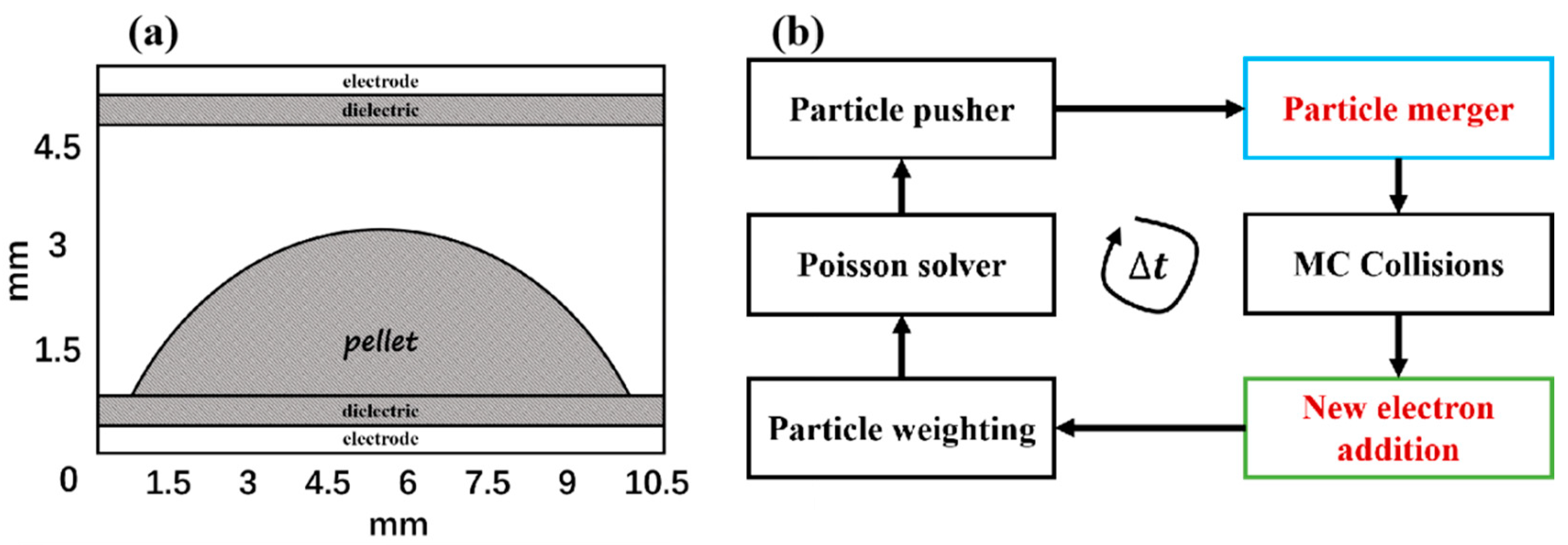
Figure 1. (a) Schematic diagram depicting the 2D simulation geometry. The electrode gap is 4 mm, the electric layer thickness is 0.4 mm, the electrode length is 11 mm, the dielectric pellet radius is 6 mm, and the pellet height is 2.4 mm. (b) Customized PIC/MCC algorithm flow chart. The weight of each superparticle is adjusted adaptively at ‘particle merger’, conserving both momentum and energy. Electrons produced via cosmic radiation, photoionization, and various secondary electron emission will be included in the “New electron addition” section.
Plasma 06 00044 g001
Figure 2. Electron density profiles, electric field distributions, and charge density distributions at three different moments, with a dielectric constant of the pellet of 4, illustrating the evolution of a plasma streamer. (ac) Electron density distribution; (df) absolute values of the electric field; (gi) charge density distributions; (a,d,g) 0.6 ns; (b,e,h) 1.44 ns; (c,f,i) 2.28 ns.
Plasma 06 00044 g002
Figure 3. Electron density profiles, electric field distributions and charge density distributions at three different moments, with a dielectric constant of the pellet of 40, illustrating the evolution of a plasma streamer. (ac) Electron density distribution; (df) absolute values of the electric field; (gi) charge density distributions; (a,d,g) 0.6 ns; (b,e,h) 1.44 ns; (c,f,i) 2.28 ns.
Plasma 06 00044 g003
Figure 4. Electron density profiles, electric field distributions, and charge density distributions at three different moments, with a dielectric constant of the pellet of 400, illustrating the evolution of a plasma streamer. (ac) Electron density distribution; (df) absolute values of the electric field; (gi) charge density distributions; (a,d,g) 0.6 ns; (b,e,h) 1.44 ns; (c,f,i) 2.28 ns.
Plasma 06 00044 g004
Disclaimer/Publisher’s Note: The statements, opinions and data contained in all publications are solely those of the individual author(s) and contributor(s) and not of MDPI and/or the editor(s). MDPI and/or the editor(s) disclaim responsibility for any injury to people or property resulting from any ideas, methods, instructions or products referred to in the content.