Article

Investigating the Effects of Gliding Arc Plasma Discharge’s Thermal Characteristic and Reactive Chemistry on Aqueous PFOS Mineralization

by
Mobish A. Shaji
1,*,
Mikaela J. Surace
2,
Alexander Rabinovich
1,
Christopher M. Sales
2,
Gregory Fridman
3,
Erica R. McKenzie
4 and
Alexander Fridman
1
1
C&J Nyheim Plasma Institute, Drexel University, Camden, NJ 08103, USA
2
Department of Civil, Architectural and Environmental Engineering, Drexel University, Philadelphia, PA 19104, USA
3
AAPlasma LLC., Philadelphia, PA 19146, USA
4
Department of Civil and Environmental Engineering, Temple University, Philadelphia, PA 19122, USA
*
Author to whom correspondence should be addressed.
Plasma 2024, 7(3), 705-720; https://doi.org/10.3390/plasma7030036
Submission received: 30 June 2024 / Revised: 21 July 2024 / Accepted: 13 August 2024 / Published: 19 August 2024

Abstract

:
Per-and Polyfluoroalkyl substances (PFASs) are recalcitrant organofluorine contaminants, which demand urgent attention due to their bioaccumulation potential and associated health risks. While numerous current treatments technologies, including certain plasma-based treatments, can degrade PFASs, their complete destruction or mineralization is seldom achieved. Extensive aqueous PFAS mineralization capability coupled with industrial-level scaling potential makes gliding arc plasma (GAP) discharges an interesting and promising technology in PFAS mitigation. In this study, the effects of GAP discharge’s thermal and reactive properties on aqueous perfluorooctanesulfonic acid (PFOS) mineralization were investigated. Treatments were conducted with air and nitrogen GAP discharges at different plasma gas temperatures to investigate the effects of plasma thermal environment on PFOS mineralization; the results show that treatments with increased plasma gas temperatures lead to increased PFOS mineralization, and discharges in air were able to mineralize PFOS at relatively lower plasma gas temperatures compared to discharges in nitrogen. Studies were conducted to identify if GAP-based PFOS mineralization is a pure thermal process or if plasma reactive chemistry also affects PFOS mineralization. This was done by comparing the effects of thermal environments with and without plasma species (air discharge and air heated to plasma gas temperatures) on PFOS mineralization; the results show that while GAP discharge was able to mineralize PFOS, equivalent temperature air without plasma did not lead to PFOS mineralization. Finally, mineralization during treatments with GAP discharges in argon and air at similar gas temperatures were compared to investigate the role of plasma species in PFOS mineralization. The results demonstrate that treatments with argon (monoatomic gas with higher ionization) lead to increased PFOS mineralization compared to treatments with air (molecular gas with lower ionization), showing the participation of reactive species in PFOS mineralization.

Graphical Abstract

1. Introduction

Per-and Polyfluoroalkyl substances (PFASs) are fluorinated organic compounds widely used for their thermal and chemical stability, high surface activity, and water and lipid repelling properties [1,2]. These characteristics stem from their strong, thermodynamically robust C-F bonds, which makes them stable and inert [3,4]. Applications of PFASs include aqueous film-forming foams, refrigerants, semiconductor coating agents, stain removers, water proofing materials, etc. [3,5]. They have been in use since the 1940s, and the widespread and broad adoption of PFASs has led to their contamination in soil, surface water, and ground water [6]. Perfluorooctanoic acid (PFOA) and perfluorooctane sulfonic acid (PFOS) were the most commonly used and are ubiquitous PFAS contaminants around the world [7]. The characteristics that make PFAS popular (C-F bond) lead to them being recalcitrant to conventional water treatment technologies and advanced oxidation processes [2]. Due to the widespread contamination of PFASs, humans are exposed to them through food web [8], the environment, and consumer products [9]. Sufficient evidence is found to associate PFAS with the following health adverse effects such as decreased antibody response, dyslipidemia, decreased infant and fetal growth, and increased risk of kidney cancer; and suggestive evidence for the following disorders: enzyme altercations, testicular and breast cancers, and thyroid and ulcerative colitis [10]. Due to the rampant PFAS contamination and its associated health risks, there is an urgency in developing pragmatic PFAS mitigation technologies.
Existing PFAS mitigation technologies can be broadly classified into separation and destruction-based technologies [11]. Separation-based technologies use filtration or adsorption approaches to remove PFASs; these technologies include: activated carbon, anion-exchange resins or polymers, biocompatible materials [4], foam fractionation or ozofractionation, and nano filtration and reverse osmosis [12]. Separation technologies often require consumables for operation and secondary treatments for ultimate PFAS destruction; drawbacks include increased operation and maintenance costs [2,12], and potential for PFAS release due to a lack of proper PFAS destruction [13]. Due to the disadvantages of separation-based PFAS mitigation, destruction-based PFAS remediation technologies are needed.
Destruction-based technologies for PFAS mitigation include sonolysis, thermal degradation, persulfate, alkaline hydrothermal treatment, microwave/persulfate, UV, ionizing radiation electron beam, gamma irradiation, non-thermal plasma, and biodegradation [1,2,4,12]. These technologies differ from each other in their ability to completely degrade (mineralize) PFASs, energy consumption, and the formation of harmful by-products during treatment, etc. Complete PFAS destruction is needed as the formation of short-chain species during treatments can result in toxicity. Among these technologies, complete mineralization is possible in treatments by sonolysis, chemical oxidation, advanced reduction processes, super critical water oxidation (SCWO), and a few non-thermal plasma-based technologies [2]. Plasma-based PFAS degradation is an interesting technology that has been noted for its effectiveness in degrading PFASs [2,4,12,14].
Plasma can be defined as a quasi-neutral fluid-like mixture of free electrons, ions, and neutral particles with a large mean kinetic energy of electrons and other plasma components [15]. Two broad classifications of plasma are thermal and non-thermal. In thermal plasma, the high-energy electrons and heavy particles such as ions are in thermal equilibrium; but, in non-thermal plasma, if there is not enough energy or pressure, thermal equilibrium between electrons and heavy particles is prevented resulting in non-equilibrium or non-thermal plasma (NTP) [16]. Industrial applications of plasma are extensive and found in multiple industries. Thermal plasma generators are not suitable for plasma chemistry applications, which require selective treatment of reactants and energy efficiency; non-thermal plasmas are suitable candidates for plasma chemistry applications [17], and their current applications include, but are not limited to, medicine, the food industry, material processing, syngas production, water treatment, and hydrogen production.
Interactions between NTP and aqueous media lead to the formation of chemically reactive species such as reactive oxygen (OH, atomic oxygen, hydrogen peroxide, etc.), reactive nitrogen species (nitrate, nitrite, peroxynitrate, peroxynitrite, etc.), shock waves, and UV radiation. These species can degrade many biological and chemical contaminants [18,19,20]. NTP-based water treatments have shown potential in degrading contaminants such as PFAS, 4-cholorphenol, diatrizoate, benzotriazole, verapamil, bisphenol A, enrofloxacin, chloramphenicol, etc. [21]. Compared to conventional technologies such as advanced oxidation processes, plasma-based water treatments feature advantages such as eliminating consumables (as chemical species are present in the discharge), higher contaminant decomposition rates, and lower operation costs as consumables are not needed [22].
While many treatment technologies can degrade PFASs, complete degradation or mineralization is achieved only in a few. The lack of PFAS mineralization during treatments leads to the formation of short-chain species, which are still toxic and thereby increases the cost of treatments due to the need for further treatments. Therefore, the efficacy and cost of PFAS degradations need to be analyzed in terms of PFAS mineralization. Plasma-based PFAS degradation has been noted for its ability to degrade PFAS [2,4,12,14], but the formation of short-chain species has often been reported as a drawback of this technology [4,23]. In a study conducted by Saleem et al. [24] on plasma-based PFAS mineralization, relatively higher energy NTP discharges such as Direct Current (DC) and Self-Pulsed Spark discharges are able to achieve higher PFAS mineralization; while reported in a different publication, microwave discharges have also exhibited good PFAS mineralization capability [25]. Higher mineralization during treatments with high-energy discharges could be due to the higher temperatures of these discharges. The high bond dissociation energy (BDE) of the C-F bond (500 kJ/mol) requires thermodynamic compensation for C-F cleavage to occur, since enthalpy of the formation of HF is lower than carbon-fluorine BDE [26]; energy input is required for PFAS mineralization. Non-plasma-based PFAS treatment technologies where high temperature make an important contribution to PFAS degradation, such as sonolysis [23,27] and supercritical water oxidation (SCWO) [6], have shown excellent potential in mineralizing PFAS with minimal short-chain PFAS formation, and increased mineralization with a rise in reaction temperatures has been observed in SCWO [6,28]. This effect of temperature is evident in a comparison of NTP-based PFAS degradation technologies, where high-energy NTP discharges such as DC [3,29], Self-Pulsed Spark [24], and microwave [25] discharges are able to mineralize PFAS with minimal short-chain formation. While treatments with low-energy discharges such as Corona and Dielectric Barrier Discharge (DBD) [4,23,24,30], having lower plasma gas temperatures [31], were not able to achieve similar levels of PFAS mineralization as the high-energy discharges. A relatively high-energy NTP discharge that has also shown extensive PFAS mineralization capability is gliding arc plasma (GAP) discharge [19,32].
Gliding arc discharges are a unique candidate in NTP-based PFAS treatments; Takeuchi et al. [33] reported GAP-based PFAS treatments by Lewis et al. [19] to have one of the highest PFAS mineralization efficiencies with respect to energy supplied per liter of volume. GAP discharges are already noted for their scaling potential up to industrial scales [34] compared to low-energy NTP discharge. These practical advantages (mineralization and scaling potential) make GAP discharge an interesting candidate for PFAS degradation. As a technology with great potential for scaling up, it is important to elucidate what characteristics of plasma contribute to PFAS mineralization during GAP treatment. Growing evidence from studies [24,33] and thermodynamic modeling [32] suggests that the thermal environment in GAP discharges plays an important role, either directly or in combination with plasma reactive species, in aiding the much-needed PFAS mineralization during treatments. During interaction between GAP discharge and an aqueous medium, plasma reactive species also interact in addition to the plasma thermal environment. As high temperatures have shown effectiveness in mineralizing aqueous PFASs during plasma-based [29] and non-plasma-based PFAS treatments [6,28], plasma reactive species such as OH radicals [23,24,25,27,35,36] and reactive nitrogen species [36] have also been reported to participate in PFAS degradation. Therefore, in this study, the effect of GAP discharge temperatures (referring to gas temperatures, detailed description provided in Section 2.5) on PFOS mineralization is investigated and investigations have been made to identify if GAP-based PFAS mineralization is a pure thermal process or whether plasma reactive species also contribute to PFOS degradation. In order to study the effect of plasma discharge temperature on PFOS mineralization, aqueous PFOS was treated with GAP discharges in air and nitrogen gases at different gas temperatures and PFOS mineralization via defluorination (definition provided in Section 2.4), and PFOS degradation were studied. To identify the contribution made by plasma on PFOS degradation (purely thermal, or synergistic effects of plasma thermal environment and reactive chemistry), treatments were conducted in treatment environments with similar plasma gas temperatures, but different plasma reactive environments. PFOS defluorination and degradation during treatments with air discharge, and air heated to approximately the same temperature as air discharge gas temperatures (with a joule heater), is compared to identify if GAP-based PFAS mineralization is a pure thermal process. The effect of plasma reactive species on PFOS degradation is investigated by comparing the results of treatments with GAP discharge in argon (discharge in monoatomic gas with higher ionization) and air (discharge in molecular gas with lower ionization) at similar gas temperatures.

2. Materials and Methods

2.1. Gliding Arc Plasma (GAP) Discharge

Gliding arc plasma discharge is characterized by formation of a thermal arc in the gap between high voltage and ground electrode at the very beginning of discharge; this arc is then elongated and cooled through forced convection by a jet of gas. The arc channel elongates until a critical length is reached, when the power supply reaches the highest power it can supply to sustain the discharge [17]. During this window, the ionization mechanism of discharge transitions from thermal step-wise ionization to non-equilibrium direct electron impact, which creates suitable conditions for non-equilibrium energy distribution, lower gas temperatures, and increased production of plasma species. As the arc elongates further, it reaches a point when the power supply can no longer sustain it, the arc self-extinguishes and then reignites in the electrode gap and the process is repeated [37]. In this study, a three-dimensional gliding arc discharge has been used, where the arc discharge is moved along the cylindrical electrode circumference using compressed air, and 3D configuration allows for better contact between the plasma zone and liquid to be treated, as well as preventing local hot spots in the electrode [38]. A detailed drawing of the GAP plasmatron (plasma system used to generate a 3D GAP [38]) used in this study is shown in Figure 1 below.

2.2. Plasma Water Treatment System

The treatment set-up (Figure 2) consists of a gliding arc plasmatron, a beaker as a reservoir for PFOS-contaminated water, and a liquid recirculation circuit. Aqueous PFOS (treatment volume: 200 mL) to be treated was kept in a 250 mL glass beaker and injected with a pump (KCP PRO-2 Adjustable Peristaltic Pump, Kamoer Fluid Tech, Shanghai, China) at flow rate of 50 mL/min into the plasmatron. A nozzle (Hago B-37) located in the high-voltage electrode, atomizes the liquid into droplets of diameter ~50 microns (according to the manufacturer’s documentation), and these droplets interact with GAP. Droplets leaving the plasmatron were collected in the same beaker. A magnetic stirrer was used for mixing the liquid during treatment, treatment duration was for 12 min and the samples were collected with the help of a pipettor from the beaker every 3 min during treatments. The system was flushed with methanol and distilled water prior to treatments, in order to remove any PFASs remaining from previous treatments. The power supply used in this study was Universal Voltronics, BRC 10,000. Since different feed gases (air, argon, and nitrogen), feed gas flow rates, and electrical powers were used in these experiments, operation parameters are attached in Section 3: Results.

2.3. Aqueous PFAS (PFOS) Preparation

The 100 mg/L solution of aqueous PFOS used in this study was prepared by adding a measured mass of PFOS (PFOSK, purity: 98%, Sigma-Aldrich, St. Louis, MO, USA) into distilled water and stirring for 2 h with heat on for one hour. Solutions were prepared in polypropylene volumetric flasks to minimize adsorption losses.

2.4. Analytical Methods

The concentration of HF or F in bulk liquid provides insight into what percentage of the parent compound has been mineralized. As fluorine is removed from the parent compound this is referred to as defluorination. In this study, defluorination was estimated with the aid of a fluoride selective electrode (ORION Ion Selective Electrode, Thermo scientific, Waltham, MA, USA; accuracy ±2%), whose measurement range was from 1 mg/L to 10 mg/L of F . The measured F concentration is converted into mass by multiplying with the volume of solution in beaker; and, it is then compared to the initial mass of fluorine in PFOS to determine %defluorination, as shown Equation (1) below:
% d e f l u o r i n a t i o n = M e a s u r e d   F m a s s M a s s   o f   F   a t o m s i n   P F O S
where M a s s   o f   F   a t o m s   i n   P F O S is estimated by Equation (2), detailed step wise calculations shown in ‘Calculation S1’ (page 6), Supplementary Information.
M a s s   o f   F   a t o m s   i n   P F O S = m o l e s   o f   F   i n   P F O S × m o l a r   m a s s   o f   F
In addition to mineralizing (or defluorination), treatment could also degrade PFOS into shorter-chain PFAS species. The effect of plasma treatment on parent PFOS was analyzed with the aid of Liquid Chromatography Quadrupole Time-Of-Flight Mass Spectrometry or LC-QTOF-MS (Sciex X500R, Framingham, MA, USA); the measurement method was same as that described by Lewis et al. [19]. The following PFASs have been looked into during the analysis to account the formation of any short-chain species: PFOS, PFBA, PFPeA, PFHxA, PFHpA, PFOA, PFNA, PFDA, PFUnA, PFDoA, PFBS, PFPeS, PFHxS, PFHpS, PFNS, PFDS, 4:2 FtS, 6:2 FtS, and 8:2 FtS.
The percentage of PFOS removed after treatment was quantified by comparing the mass of PFOS removed after treatment to the initial PFOS mass. The measured PFOS concentration is converted into mass by multiplying it with the volume of solution in the beaker; and, it is then compared to the initial mass of PFOS to determine PFOS degradation, as shown in Equation (3) below:
% P F O S   R e m o v e d = 1 P F O S   m a s s   m e a s u r e d I n i t i a l   P F O S   m a s s
If any short-chain PFAS concentrations were measured, they were converted to mass by multiplying them with the volume of solution in the beaker, and they were compared to the initial PFOS mass to determine the formation of short-chain PFASs during treatment. Using the percentage of inorganic fluoride produced as a result of mineralization (%defluorination) and the percentage of organic fluoride still remaining in the parent PFOS and any short-chain species, fluorine mass balance showing the effect of treatment on PFOS is created.

2.5. Plasma Gas Temperature Estimation

As the effect of temperatures in a plasma discharge is discussed, it is important to define the temperature being studied. Effective temperatures present in non-thermal plasma (NTP) are as follows: gas (kinetic or translational), and rotational and vibrational temperatures. Among these, gas temperature is of primary importance, as it affects the reaction rate constants and plasma density [15]. Gas temperatures in NTP are usually determined using emission, adsorption spectroscopy [15], or Rayleigh scattering thermometry [39,40]. In this study ~ average gas temperatures during GAP discharges were theoretically determined with the aid of average energy, based on the principles described below.
Gliding arc plasma (GAP) discharges transition rapidly from the initial quasi equilibrium to the non-equilibrium phase because of strong non-linear ionization instability; during this instability, the phenomenon of rapid discharge length explosion results in discharge parameters that are sufficient for supporting a relatively cold plasma. After this transition, GAP discharge has strong non-equilibrium characteristics, with heavy particle temperatures significantly lower than electron temperatures [17]. Due to the lack of local thermodynamic equilibrium in non-thermal plasmas, its temperature is a characteristic of average energy [15]. As gliding arc discharge rapidly transitions to the non-equilibrium phase, its gas temperature will be dominantly influenced by energy supplied for ionization rather than by electron collisions. Therefore, the ~average plasma gas temperatures of GAP discharge were estimated by using average energy (assuming a 100% conversion of electrical energy to heat energy), as shown below:
E = m ˙ c p T
where E is the electrical power supplied,
m ˙ is the mass flow rate of feed gas,
c p is the specific heat of the feed gas,
and T is the change in temperature of the feed gas.
As E, m ˙ , and c p are known, T can be found from Equation (4), and the temperature of gas after ionization (or ~ average plasma gas temperature) can be found with the aid of T and the initial temperature. There were volume losses due to evaporation during experiments, and thereby some amount of the energy supplied is lost as heat of vaporization for water (2260 J/g); since this energy is lost, the ~ average plasma gas temperature was estimated with energy that has been accounted for this loss (examples of these estimations can be found in Tables S1 and S2 in Supplementary Information).

2.6. Thermal Imaging

Thermal imaging (Seek Thermal, Santa Barbara, CA, USA; accuracy: ±5%) was performed to validate the estimations of gas temperature mentioned in Section 2.5. Thermal imaging reports lower temperatures than those estimated by the average energy values. Possible reasons could be loss of heat energy to walls of the plasmatron, which are exposed to air at room temperature. Water droplets inside of the reactor during treatments could be exposed to temperatures that are close to those estimated via average energy.

3. Results

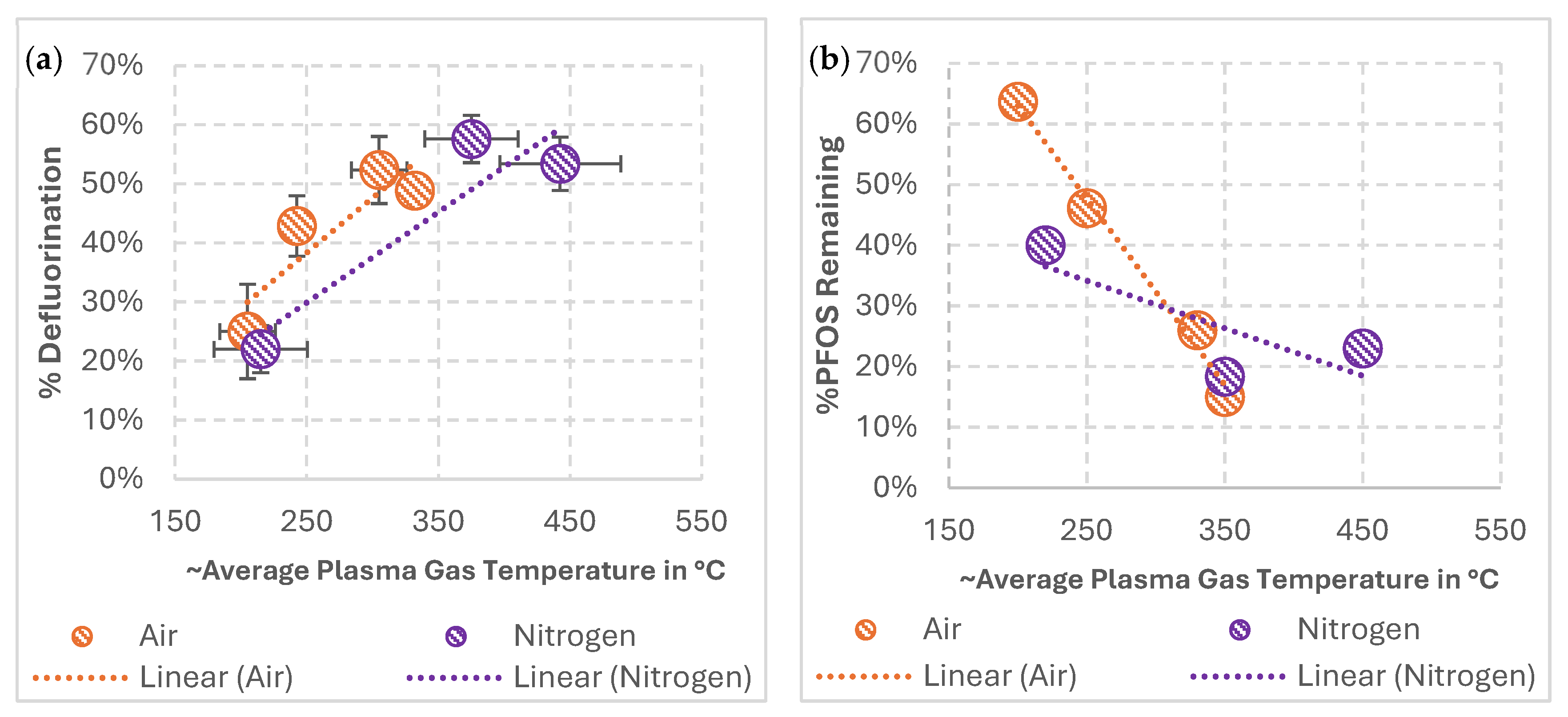
3.1. Impact of Average Plasma Gas Temperatures on PFOS Mineralization during Treatments in Air and Nitrogen GAP Discharges

Since increase in temperatures have been reported to aid aqueous PFAS mineralization [6,29,32], the influence of GAP discharge temperatures on PFOS defluorination and degradation is investigated. Aqueous PFOS was treated with GAP discharges at different plasma gas temperatures; this was done by varying the electrical power supplied to the discharge. Details of each of these treatments are as mentioned in Section 2.2; treatments were performed in air and nitrogen GAP discharges at different gas temperatures. The operating parameters of these treatments are provided in Supplementary Data (Tables S1 and S2). Estimations of gas temperatures, according to Equation (4), for air and nitrogen discharges discussed here are also provided in Tables S1 and S2 in the Supplementary Information; thermal images of the reactor are provided in Figure S1 to validate the estimations, since air and nitrogen gas have similar specific heats, only thermal images of the air GAP discharges are reported here. The percentage of PFOS defluorination and the percentage of PFOS remaining after treatments with GAP discharge in air and nitrogen gases as a function of ~average plasma gas temperatures are shown in Figure 3. Experiments were performed in duplicates, %defluorination was measured for both treatments, and the percentage of remaining PFOS was analyzed for one of the treatments.
The results show that, during treatments with GAP discharges in air and nitrogen gases, increased plasma gas temperatures leads to increased PFOS defluorination. Similar observations can be found with the degradation of PFOS shown in Figure 3b; increased plasma gas temperatures lead to the increased degradation of PFOS. Short-chain PFAS formation was not observed (Figure S2) based on LC-QTOF-MS analysis, which investigated for all the PFAS species listed in methodology, indicating mineralization of PFOS during treatment with air and nitrogen discharges. The average %defluorination results for duplicate treatments (Figure 3a) show that discharges in air are able to defluorinate PFOS at relatively lower gas temperatures than discharges in nitrogen; this behavior could be due to the difference in reactive environment in air and nitrogen discharges. A further analysis of these results with previous studies from the literature is conducted in Section 4.1.

3.2. Role Played by GAP Discharge on PFOS Mineralization: Purely Thermal or Does Plasma Reactive Chemistry Affect PFOS Mineralization

To understand the role played by GAP discharge in mineralizing PFOS (whether it is purely thermal or a synergistic effect of plasma thermal and reactive environment), PFOS degradation in an air GAP discharge treatment is compared with treatments in a pure thermal environment with temperatures similar to gas temperature of the air discharge. A thermal environment similar to GAP discharge but without any plasma reactive species was produced by using air heated to the plasma gas temperature as a feed gas, and without supplying any electrical energy to the system (Figure S4). The operating parameters of air discharge treatments are provided in Table 1. For the heated air experiment, the flow rate of feed gas was 50 SCFH, so that aqueous PFAS will have a higher residence time in the reactor (details provided in Section 4: Discussion) compared to air discharge treatment.
The parameters in Table 1 resulted in an average plasma gas temperature of ~300 °C in the air discharge, details of these calculations are the same as that for experiment number 3 in Table S1 (Supplementary Information). In order to have a gas temperature similar to GAP discharge but without any plasma species, air was heated to this gas temperature (300 °C) with the aid of a joule heater (Figure S4). Thermal images of the reactor during operation with air GAP discharge and with air heated to 300 °C are shown in Figure 4. While the predicted gas temperature in air discharge was ~300 °C, a lower temperature is reported by thermal imaging; possible reasons could include the loss of heat through the reactor wall to surrounding air at room temperature. The constant addition of heated air from the joule heater could have helped the reactor to be at higher temperatures during operation with heated air compared to air discharge. Also, the overall volume of hot gas is higher with heated air experiments, as air is at higher temperatures from the feed gas injection ports onwards, compared to just the discharge zone in the case of air GAP discharge.
These experiments were performed with multiple passes through the reactor (Figures S3 and S4). As plasma is the source of temperature in the GAP treatment system, multiple passes through the reactor allow a controlled interaction with plasma and helps us to observe the contribution of each pass or the interaction with plasma on PFOS degradation. During the 12 min recirculation treatment (Figure 2), a liquid flow rate of 50 mL/min allows 200 mL of aqueous PFOS to make ~3–4 passes in the system. Hence, in this investigation, aqueous PFOS was passed four times through the reactor during treatment with air GAP discharge and heated air; with each pass taking about ~3 min on average, (lower than 4 min due to volume loss occurring in treatment; this time is based on the measurement conducted during multiple passes). Samples were collected at the end of each pass from the beaker at the plasmatron’s exit and analyzed for %defluorination and the percentage of remaining PFOS and other compounds. The results are shown in the following Figure 5.
The results show that while multiple passes of aqueous PFOS through GAP discharge at ~300 °C led to defluorination, as shown in Figure 5a, no such defluorination was found during multiple passes through air heated to ~300 °C. While PFOS removal is found in both treatments, the incomplete fluorine mass balance (Figure S5) indicates that some PFOS could be lost, possibly as aerosols during this mode of operation. In the case of GAP discharge, defluorination indicates partial mineralization of PFOS; and, in the case of heated air, a lack of defluorination and short-chain species indicate a lack of PFOS mineralization. These results show that PFOS defluorination in GAP-based treatments are not pure thermal processes and plasma reactive chemistry seems to make contributions towards PFOS degradation. A further analysis of the results with comparisons from the literature is conducted in Section 4.2.

3.3. Effects of Different Plasma Reactive Chemistries on PFOS Mineralization

In order to see the effect of different plasma reactive environments on PFOS mineralization, aqueous PFOS was treated in air and argon discharge at the operation parameters listed in Table 2, which resulted in similar plasma gas temperatures (~100 °C) in both of them. Estimations of plasma gas temperatures and thermal images of the reactor during operation with these parameters are shown in Table S3 and Figure S6, respectively. The results of treatments with air and argon discharges are provided in Figure 6.
The results show that while operating with similar gas temperatures, treatments in argon discharges resulted in higher PFOS defluorination and PFOS degradation, compared to treatments in air discharges. The monoatomic nature of argon gas allows higher ionization in it compared to air (molecular gas), and hence the formation of plasma reactive species are higher during the interaction with water and argon discharges compared to air discharges [41,42]. These results show the role of plasma reactive species on PFOS mineralization in addition to the effects of gas temperatures. Further discussions with literature review are provided in Section 4.3.

4. Discussion

4.1. Impact of Average Plasma Gas Temperatures on PFOS Mineralization

PFOS treatments with GAP discharge at different plasma gas temperatures (Section 3.1) showed that increased gas temperatures lead to increased PFOS defluorination and degradation in both air and nitrogen discharges. Neither gas resulted in short-chain PFAS formation (Figure S2), and PFOS treatment with air and nitrogen discharges resulted in F- formation (i.e., mineralization). Higher temperatures could be providing the necessary thermodynamic compensation required for PFOS mineralization [26]; the application of relatively higher energy (or higher temperature) NTP discharges could address the disadvantage of low mineralization in low-energy NTP-based PFAS treatment [12]. The highest mineralization achieved during treatments with air discharge was ~50%, and nitrogen discharges were ~60%. Possible reasons for mineralization being limited to these values could be the limited treatment time of 12 min. This relationship of increase in mineralization with increase in temperature agrees with the modeling and experimental results for PFAS treatments in NTP [32] and other PFAS treatment systems [6]. It is also interesting to note that air discharges are able to mineralize PFOS at relatively lower gas temperatures compared to nitrogen discharges. In a previous GAP-based PFOS treatment, Lewis et al. [19] observed higher PFOS destruction during treatments with air GAP discharge compared to nitrogen GAP discharge; the authors suggested the possible involvement of reactive oxygen species (ROS) and reactive nitrogen species (RNS) in the degradation mechanism. A higher generation of OH radicals (ROS) and nitrates (RNS) are observed during air GAP interaction with water compared to nitrogen GAP interaction with water [41]. PFOS mineralization at relatively lower temperatures by air discharges might be indicative of ROS and RNS involvement in GAP-based PFOS degradation mechanisms, but further investigations are required for identifying the effect of specific plasma species on PFOS degradation during GAP treatment. Further, these results indicate that solvated (hydrated) electrons might not be a major plasma reactive species contributing to PFOS degradation during treatments with air GAP discharge, as electronegative oxygen molecules quickly react with electrons, reducing their flux in solutions in contact with air discharges [43,44], compared to nitrogen discharges.

4.2. Role Played by GAP Discharge on PFOS Mineralization

Comparing PFOS defluorination during multiple pass treatments with air GAP discharge and air heated to plasma gas temperatures (Section 3.2) showed that GAP-based PFOS degradation is not a pure thermal process, as the presence of temperatures similar to GAP discharge without the presence of plasma species did not lead to PFOS defluorination. While there was a reduction in PFOS mass during treatments with heated air, a lack of defluorination and a lack of short-chain PFAS formation (see fluorine mass balance in Figure S5b) point to the potential loss of PFOS during treatments (possibly via aerosolization) instead of PFOS degradation. A targeted PFAS analysis for samples from the multiple pass treatments with air GAP discharge (Figure S5a) shows no formation of short-chain species, but defluorination during these treatments shows mineralization of PFOS during air GAP treatments. In this discussion, the possible reasons why temperatures similar to plasma gas temperature failed to mineralize PFOS are analyzed. During treatment, water droplets are carried by feed gas (in this case, air) at a flow of rate 50 SCFH or ~23 LPM or 4 × 10 4   m 3 / s through the plasmatron, the distance water droplets interact with plasma is about ~35 mm (Figure 1), and the area of the circular cross-section is about 7.8 × 10 5   m 2 giving the air flow a velocity of 5   m / s or water droplets a residence time of ~7 milliseconds. This fast interaction could be a reason for the lack of observable PFOS mineralization due to the thermal environment. Modeling on thermal degradation of PFOS has shown the half-life of PFOS at 726 °C to be 0.2 s [45], and residences times of 2–4 s are required at 1,100 °C for the proper incineration of PFOS [46,47]. During the air GAP discharge treatments with an 80 SCFH flow rate of feed gas (Table 1), the residence time came to ~4.4 milliseconds, which is much faster than that in the heated air experiments. These results show that the plasma reactive environment also plays an important role in the degradation of PFOS in addition to plasma gas temperatures during treatments. About ~40% fluorine is unaccounted for in the fluorine mass balance for air GAP discharge samples (Figure S5a), and 40–70% fluorine is unaccounted for in fluorine mass balance of heated air treatment samples (Figure S5b); this significant loss in fluorine mass might be due to PFOS loss occurring in treatments with the multiple pass configuration (possibly via aerosolization).

4.3. Effects of Different Plasma Reactive Chemistries on PFOS Mineralization

Treatments with air and argon discharges at similar gas temperatures (Section 3.3) showed that higher PFOS defluorination and degradation occur during treatments with argon discharges. This could be attributed to different reactive environments in argon and air GAP discharges. Discharges in monoatomic gases, such as argon, have higher ionization compared to discharges in molecular gases, such as air and nitrogen, due to the lack of vibrational and rotational losses in monoatomic discharges [48,49]. Higher ionization in argon discharges compared to air discharges allows it to have a higher electron density and a higher production of ROS such as H 2 O 2 [41,42], and O 3 [42] during interaction with water. The higher PFOS defluorination and degradation during treatments with argon discharge relative to air discharge, while both were at the same gas temperatures, shows the influence of plasma reactive chemistry in PFOS degradation in addition to plasma gas temperatures. No short-chain PFAS was measured in the samples during treatments with either air or argon discharge, indicating PFOS mineralization during both treatments (see Figure S7).

4.4. Discussions Regarding This Study and Recommendations for Future Studies

Fluorine mass balances of samples (Figures S2, S5 and S7) during all these treatments show a minimal formation of short-chain PFAS species, indicating effective PFOS degradation during treatments with GAP discharge. As previously discussed, such effective degradation is achieved only in a handful of other plasma discharges such as DC [3,29], Self-Pulsed Spark [24], and microwave [25]; and, in non-plasma-based technologies such as sonolysis [23,27], chemical oxidation, advanced reduction processes [2], and supercritical water oxidation [6]. Another important factor to be considered in a PFAS treatment technology is its scaling-up potential [22]; while many plasma systems have limited scalability, GAP discharges have been found to have industrial-level scalability [34]. These characteristics of PFOS mineralization capability and potential to be scaled up makes GAP discharge an interesting candidate in PFOS mitigation.
The incomplete fluorine mass balance raises the question about the fate of fluorine that is not accounted for. For heated air treatment, the lack of fluoride and short-chain species point to a potential lack of PFAS degradation. For treatments with GAP discharge, the production of F shows the degradation and mineralization (via defluorination) of PFOS. Similar incomplete fluorine mass balances (~30%) were reported in some plasma-based PFAS treatment studies [29,33] as well. During a gas phase product analysis (gas chromatography) conducted in one of those studies by Tachibana et al. [29], the authors identified C H F 3 ,   C 2 H F 5 ,   a n d   C 2 F 6 being released from their reactor during PFOS treatments; Takeuchi et al. [33] suggest the formation of gaseous carbon fluorides such as C H F 3   a n d   C 2 F 6 for the incomplete fluorine mass balance in their study. The formation of such gas phase carbon fluorides could be a source of missing fluorine mass in the present study as well. The experimental system used in this study was not amenable to gaseous sample collection; analysis of potential gaseous products was not evaluated in this study, so it is acknowledged that volatile organic fluorine species may have been created and released. The well-sealed experimental system used by Tachibana et al. allowed their system to be amenable to a proper gas phase product analysis. A major area of improvement where future studies could focus on is optimal reactor designs for implementing gas phase product analysis.
The performed liquid phase product analysis (fluoride ISE and LC-QTOF-MS) provides little information into the fate of carbon and sulfonic acid present in the parent compound. Tachibana et al. [29] investigated the fate of carbon during treatments with the aid of high-performance liquid chromatography-mass spectrometry (HPLC-MS) and gas chromatography; the results showed a carbon mass balance consisting predominantly of carbon dioxide (~34.2%), carbon monoxide (~18.5%), PFCAs (3%), PFOS (~2%), and the remaining ~40% was unaccounted for. Similar transformations could be happening to carbon present in PFOS during GAP-based degradations as well. Regarding the fate of sulfonic acid, previous plasma-based studies [24,29] suggest the formation of sulfate in the liquid phase as a result of PFOS mineralization, similar transformations could be happening in GAP-based PFOS degradation as well.
While the estimated plasma gas temperatures in this study provided insights into the effect of temperature on PFOS mineralization, future studies should also focus on determining the temperature between GAP discharge and water droplets with the aid of feasible measurements. This is made challenging by the confinement of discharge into the plasmatron in certain operating conditions, but such measurements could provide greater insights into temperatures required for PFOS mineralization. Also, while results point to the possible involvement of ROS and RNS in air GAP-based PFOS degradation, detailed investigations should be made to identify the specific reactive species partaking in GAP-based PFOS degradation. Future studies could make use of diagnostic tools that are available for studying plasma reactive species in the liquid phase to identify potential reactive species partaking in PFOS degradation; UV/Vis spectrophotometry [50] is a cost-effective and relatively simple diagnostic tool that could potentially be used for this need. Another area of improvement for future studies is investigating the effect of aqueous PFOS droplet sizes on treatment efficiency. The amount of PFOS at the surface of a droplet relative to its volume could be adjusted by changing the size of the droplets, which could potentially enhance the treatment efficiency.

5. Conclusions

The ubiquitous contamination of the recalcitrant organofluorine compounds called PFASs and severe health risks associated with them creates an urgency in developing technologies that can destroy them. Gliding arc plasma (GAP) discharge is a promising technology that can mineralize PFASs and has industrial-level scaling potential. In this study, the effect of GAP discharge’s thermal characteristics (gas temperature) and reactive chemistry on PFOS degradation was investigated, and the results found the following:
  • Treatments with increased plasma gas temperatures in air and nitrogen GAP discharges led to increased PFOS mineralization.
  • GAP-based PFOS mineralization is not a pure thermal process, as gas temperatures similar to plasma gas temperatures but without the presence of plasma reactive species failed to mineralize PFOS.
  • Treatments with argon GAP discharges were able to achieve higher PFOS mineralization relative to treatments with air GAP discharges at similar gas temperatures, indicating the involvement of plasma reactive species in PFOS mineralization.
  • GAP discharge in air was able to mineralize PFOS at relatively lower gas temperatures than GAP discharge in nitrogen gas, indicating the possible involvement of reactive oxygen and reactive nitrogen species in PFOS mineralization.

Supplementary Materials

The following supporting information can be downloaded at: https://www.mdpi.com/article/10.3390/plasma7030036/s1. Figure S1: thermal images of the reactor during operation in air GAP discharge when the predicted ~average plasma gas temperature was: (A) ~200 °C, (B) ~250 °C, (C) ~300 °C, and (D) ~350 °C; Figure S2: fluorine mass balance of samples during treatments with GAP discharges in (a) air and (b) nitrogen at different plasma gas temperatures; Figure S3: a schematic of the reactor in multiple pass mode of operation; Figure S4: a schematic of the reactor during treatments where air heated to ~300 °C was used as a feed gas and without supplying any energy; Figure S5: fluorine mass balance of samples during multiple pass treatments with (a) GAP discharges in air and (b) heated air; Figure S6: thermal images of reactor during operation under (a) argon discharge and (b) air discharge with operation parameters as provided in Table 2; Figure S7: fluorine mass balance of samples during treatments with GAP discharges in (a) argon and (b) air; Table S1: an estimation of ~average plasma gas temperatures, accounted for evaporation during treatments in air GAP discharge; Table S2: an estimation of ~average plasma gas temperatures, accounted for evaporation during treatments in nitrogen GAP discharge; Table S3: an estimation of ~average plasma gas temperatures, accounted for evaporation during treatments in air and argon GAP discharges discussed in Section 3.3 (details of the duplicate experiments are provided); and Calculation S1: estimating the mass of fluorine in PFOS.

Author Contributions

Conceptualization, A.R., C.M.S. and A.F.; methodology, A.R., C.M.S., G.F., E.R.M. and A.F.; formal analysis, M.A.S. and M.J.S.; investigation, M.A.S. and M.J.S.; writing—original draft preparation, M.A.S.; writing—review and editing, A.R., C.M.S., G.F., E.R.M. and A.F.; supervision, A.R., C.M.S., G.F., E.R.M. and A.F.; project administration, A.R., C.M.S., G.F., E.R.M. and A.F.; funding acquisition, C.M.S. All authors have read and agreed to the published version of the manuscript.

Funding

This research was funded by the Strategic Environmental Research and Development Program (SERDP), project number ER18-1570.

Institutional Review Board Statement

Not applicable.

Informed Consent Statement

Not applicable.

Data Availability Statement

The data that support the findings of this study are available from the corresponding author, M.A.S., upon request.

Acknowledgments

Gary Nirenberg and Alexandr Blackbay at the C&J Nyheim Plasma Institute for their valuable engineering support. Jimmy Murillo-Gelvez and Yaseen H Al-Qaraghuli at Temple University for their valuable assistance with LC-QTOF-MS analysis.

Conflicts of Interest

Author Gregory Fridman was employed by the company AAPlasma LLC. The remaining authors declare that the research was conducted in the absence of any commercial or financial relationships that could be construed as a potential conflict of interest.

References

  1. Kucharzyk, K.H.; Darlington, R.; Benotti, M.; Deeb, R.; Hawley, E. Novel Treatment Technologies for PFAS Compounds: A Critical Review. J. Environ. Manag. 2017, 204, 757–764. [Google Scholar] [CrossRef] [PubMed]
  2. Nzeribe, B.N.; Crimi, M.; Mededovic Thagard, S.; Holsen, T.M. Physico-Chemical Processes for the Treatment of Per- And Polyfluoroalkyl Substances (PFAS): A Review. Crit. Rev. Environ. Sci. Technol. 2019, 49, 866–915. [Google Scholar] [CrossRef]
  3. Hayashi, R.; Obo, H.; Takeuchi, N.; Yasuoka, K. Decomposition of Perfluorinated Compounds in Water by DC Plasma within Oxygen Bubbles. Electr. Eng. Jpn. 2015, 190, 9–16. [Google Scholar] [CrossRef]
  4. Verma, S.; Lee, T.; Sahle-Demessie, E.; Ateia, M.; Nadagouda, M.N. Recent Advances on PFAS Degradation via Thermal and Nonthermal Methods. Chem. Eng. J. Adv. 2023, 13, 100421. [Google Scholar] [CrossRef] [PubMed]
  5. Trojanowicz, M.; Bojanowska-Czajka, A.; Bartosiewicz, I.; Kulisa, K. Advanced Oxidation/Reduction Processes Treatment for Aqueous Perfluorooctanoate (PFOA) and Perfluorooctanesulfonate (PFOS)—A Review of Recent Advances. Chem. Eng. J. 2018, 336, 170–199. [Google Scholar] [CrossRef]
  6. Austin, C.; Li, J.; Moore, S.; Purohit, A.; Pinkard, B.R.; Novosselov, I.V. Destruction and Defluorination of PFAS Matrix in Continuous-Flow Supercritical Water Oxidation Reactor: Effect of Operating Temperature. Chemosphere 2023, 327, 138358. [Google Scholar] [CrossRef]
  7. Podder, A.; Sadmani, A.H.M.A.; Reinhart, D.; Chang, N.-B.; Goel, R. Per and Poly-Fluoroalkyl Substances (PFAS) as a Contaminant of Emerging Concern in Surface Water: A Transboundary Review of Their Occurrences and Toxicity Effects. J. Hazard. Mater. 2021, 419, 126361. [Google Scholar] [CrossRef]
  8. Singh, K.; Kumar, N.; Kumar Yadav, A.; Singh, R.; Kumar, K. Per-and Polyfluoroalkyl Substances (PFAS) as a Health Hazard: Current State of Knowledge and Strategies in Environmental Settings across Asia and Future Perspectives. Chem. Eng. J. 2023, 475, 145064. [Google Scholar] [CrossRef]
  9. Sunderland, E.M.; Hu, X.C.; Dassuncao, C.; Tokranov, A.K.; Wagner, C.C.; Allen, J.G. A Review of the Pathways of Human Exposure to Poly- and Perfluoroalkyl Substances (PFASs) and Present Understanding of Health Effects. J. Expo. Sci. Environ. Epidemiol. 2019, 29, 131–147. [Google Scholar] [CrossRef]
  10. National Academies of Sciences, Engineering, and Medicine; Health and Medicine Division; Division on Earth and Life Studies; Board on Population Health and Public Health Practice; Board on Environmental Studies and Toxicology; Committee on the Guidance on PFAS Testing and Health Outcomes. Guidance on PFAS Exposure, Testing, and Clinical Follow-Up; Consensus Study Report; National Academies Press: Washington, DC, USA, 2022; ISBN 978-0-309-48244-8. [Google Scholar]
  11. Yadav, S.; Ibrar, I.; Al-Juboori, R.A.; Singh, L.; Ganbat, N.; Kazwini, T.; Karbassiyazdi, E.; Samal, A.K.; Subbiah, S.; Altaee, A. Updated Review on Emerging Technologies for PFAS Contaminated Water Treatment. Chem. Eng. Res. Des. 2022, 182, 667–700. [Google Scholar] [CrossRef]
  12. Wanninayake, D.M. Comparison of Currently Available PFAS Remediation Technologies in Water: A Review. J. Environ. Manag. 2021, 283, 111977. [Google Scholar] [CrossRef]
  13. Kah, M.; Oliver, D.; Kookana, R. Sequestration and Potential Release of PFAS from Spent Engineered Sorbents. Sci. Total Environ. 2021, 765, 142770. [Google Scholar] [CrossRef] [PubMed]
  14. Meegoda, J.N.; Bezerra de Souza, B.; Casarini, M.M.; Kewalramani, J.A. A Review of PFAS Destruction Technologies. Int. J. Environ. Res. Public Health 2022, 19, 16397. [Google Scholar] [CrossRef] [PubMed]
  15. Hippler, R.; Schoenbach, K.H.; Kersten, H.; Schmidt, M. Low Temperature Plasmas: Fundamentals, Technologies, and Techniques; Wiley: Hoboken, NJ, USA, 2008. [Google Scholar]
  16. Fridman, A. Plasma Chemistry; Cambridge University Press: New York, NY, USA, 2008. [Google Scholar]
  17. Fridman, A.; Nester, S.; Kennedy, L.A.; Saveliev, A.; Mutaf-Yardimci, O. Gliding Arc Gas Discharge. Prog. Energy Combust. Sci. 1999, 25, 211–231. [Google Scholar] [CrossRef]
  18. Bruggeman, P.; Leys, C. Non-Thermal Plasmas in and in Contact with Liquids. J. Phys. Appl. Phys. 2009, 42, 053001. [Google Scholar] [CrossRef]
  19. Lewis, A.J.; Joyce, T.; Hadaya, M.; Ebrahimi, F.; Dragiev, I.; Giardetti, N.; Yang, J.; Fridman, G.; Rabinovich, A.; Fridman, A.A.; et al. Rapid Degradation of PFAS in Aqueous Solutions by Reverse Vortex Flow Gliding Arc Plasma. Environ. Sci. Water Res. Technol. 2020, 6, 1044–1057. [Google Scholar] [CrossRef]
  20. Zhou, R.; Zhou, R.; Wang, P.; Xian, Y.; Mai-Prochnow, A.; Lu, X.; Cullen, P.J.; Ostrikov, K.; Bazaka, K. Plasma-Activated Water: Generation, Origin of Reactive Species and Biological Applications. J. Phys. Appl. Phys. 2020, 53, 303001. [Google Scholar] [CrossRef]
  21. Progress of Organic Wastewater Degradation by Atmospheric Pressure Gliding Arc Plasma Technology: A Review|AIP Advances|AIP Publishing. Available online: https://pubs.aip.org/aip/adv/article/14/3/030702/3269921/Progress-of-organic-wastewater-degradation-by (accessed on 2 April 2024).
  22. Foster, J.E. Plasma-Based Water Purification: Challenges and Prospects for the Future. Phys. Plasmas 2017, 24, 055501. [Google Scholar] [CrossRef]
  23. Sidnell, T.; Wood, R.J.; Hurst, J.; Lee, J.; Bussemaker, M.J. Sonolysis of Per- and Poly Fluoroalkyl Substances (PFAS): A Meta-Analysis. Ultrason. Sonochem. 2022, 87, 105944. [Google Scholar] [CrossRef]
  24. Saleem, M.; Tomei, G.; Beria, M.; Marotta, E.; Paradisi, C. Highly Efficient Degradation of PFAS and Other Surfactants in Water with Atmospheric RAdial Plasma (RAP) Discharge. Chemosphere 2022, 307, 135800. [Google Scholar] [CrossRef]
  25. Sun, S.; Sun, B.; Zhu, X.; Yang, Y.; Liu, H. Defluorination of Per-Fluorinated Compound (PFC) by Microwave Discharge Plasma in Liquid: A Green and Efficient Water Treatment Technology. Sep. Purif. Technol. 2023, 319, 124071. [Google Scholar] [CrossRef]
  26. Kuehnel, M.F.; Lentz, D.; Braun, T. Synthesis of Fluorinated Building Blocks by Transition-Metal-Mediated Hydrodefluorination Reactions. Angew. Chem. Int. Ed. 2013, 52, 3328–3348. [Google Scholar] [CrossRef]
  27. Vecitis, C.D.; Park, H.; Cheng, J.; Mader, B.T.; Hoffmann, M.R. Kinetics and Mechanism of the Sonolytic Conversion of the Aqueous Perfluorinated Surfactants, Perfluorooctanoate (PFOA), and Perfluorooctane Sulfonate (PFOS) into Inorganic Products. J. Phys. Chem. A 2008, 112, 4261–4270. [Google Scholar] [CrossRef]
  28. Pinkard, B.R.; Shetty, S.; Stritzinger, D.; Bellona, C.; Novosselov, I.V. Destruction of Perfluorooctanesulfonate (PFOS) in a Batch Supercritical Water Oxidation Reactor. Chemosphere 2021, 279, 130834. [Google Scholar] [CrossRef]
  29. Tachibana, K.; Takeuchi, N.; Yasuoka, K. Reaction Process of Perfluorooctanesulfonic Acid (PFOS) Decomposed by DC Plasma Generated in Argon Gas Bubbles. IEEE Trans. Plasma Sci. 2014, 42, 786–793. [Google Scholar] [CrossRef]
  30. Saleem, M.; Biondo, O.; Sretenović, G.; Tomei, G.; Magarotto, M.; Pavarin, D.; Marotta, E.; Paradisi, C. Comparative Performance Assessment of Plasma Reactors for the Treatment of PFOA; Reactor Design, Kinetics, Mineralization and Energy Yield. Chem. Eng. J. 2020, 382, 123031. [Google Scholar] [CrossRef]
  31. Yang, Y.; Cho, Y.I.; Fridman, A. Plasma Discharge in Liquid: Water Treatment and Applications; CRC Press: Boca Raton, FL, USA, 2017; ISBN 978-1-315-21707-9. [Google Scholar]
  32. Surace, M.J.; Murillo-Gelvez, J.; Shaji, M.A.; Fridman, A.A.; Rabinovich, A.; McKenzie, E.R.; Fridman, G.; Sales, C.M. Plasma-Assisted Abatement of Per- and Polyfluoroalkyl Substances (PFAS): Thermodynamic Analysis and Validation in Gliding Arc Discharge. Plasma 2023, 6, 419–434. [Google Scholar] [CrossRef]
  33. Takeuchi, N.; Suzuki, D.; Okada, K.; Oishi, K.; Kodama, S.; Namihira, T.; Wang, D. Discharge Conditions for Efficient and Rapid Decomposition of Perfluorooctane Sulfonic Acid (PFOS) in Water Using Plasma. Int. J. Plasma Environ. Sci. Technol. 2020, 14, e02006. [Google Scholar]
  34. Rabinovich, A.; Nirenberg, G.; Kocagoz, S.; Surace, M.; Sales, C.; Fridman, A. Scaling Up of Non-Thermal Gliding Arc Plasma Systems for Industrial Applications. Plasma Chem. Plasma Process. 2022, 42, 35–50. [Google Scholar] [CrossRef]
  35. Weber, N.H.; Delva, C.S.; Stockenhuber, S.P.; Grimison, C.C.; Lucas, J.A.; Mackie, J.C.; Stockenhuber, M.; Kennedy, E.M. Thermal Mineralization of Perfluorooctanesulfonic Acid (PFOS) to HF, CO2, and SO2. Ind. Eng. Chem. Res. 2023, 62, 881–892. [Google Scholar] [CrossRef]
  36. Zhu, D.; Sun, Z.; Zhang, H.; Zhang, A.; Zhang, Y.; Miruka, A.C.; Zhu, L.; Li, R.; Guo, Y.; Liu, Y. Reactive Nitrogen Species Generated by Gas–Liquid Dielectric Barrier Discharge for Efficient Degradation of Perfluorooctanoic Acid from Water. Environ. Sci. Technol. 2022, 56, 349–360. [Google Scholar] [CrossRef]
  37. Gallagher, M.J.; Geiger, R.; Polevich, A.; Rabinovich, A.; Gutsol, A.; Fridman, A. On-Board Plasma-Assisted Conversion of Heavy Hydrocarbons into Synthesis Gas. Fuel 2010, 89, 1187–1192. [Google Scholar] [CrossRef]
  38. Cho, Y.; Wright, K.; Kim, H.; Cho, D.; Rabinovich, A.; Fridman, A. Stretched Arc Discharge in Produced Water. Rev. Sci. Instrum. 2015, 86, 013501. [Google Scholar] [CrossRef] [PubMed]
  39. Zhu, J.; Ehn, A.; Gao, J.; Kong, C.; Aldén, M.; Salewski, M.; Leipold, F.; Kusano, Y.; Li, Z. Translational, Rotational, Vibrational and Electron Temperatures of a Gliding Arc Discharge. Opt. Express 2017, 25, 20243. [Google Scholar] [CrossRef] [PubMed]
  40. Kong, C.; Li, Z.; Aldén, M.; Ehn, A. Thermal Analysis of a High-Power Glow Discharge in Flowing Atmospheric Air by Combining Rayleigh Scattering Thermometry and Numerical Simulation. J. Phys. Appl. Phys. 2020, 53, 085502. [Google Scholar] [CrossRef]
  41. Du, C.M.; Sun, Y.W.; Zhuang, X.F. The Effects of Gas Composition on Active Species and Byproducts Formation in Gas–Water Gliding Arc Discharge. Plasma Chem. Plasma Process. 2008, 28, 523–533. [Google Scholar] [CrossRef]
  42. Rathore, V.; Nema, S.K. The Role of Different Plasma Forming Gases on Chemical Species Formed in Plasma Activated Water (PAW) and Their Effect on Its Properties. Phys. Scr. 2022, 97, 065003. [Google Scholar] [CrossRef]
  43. Rumbach, P.; Bartels, D.M.; Sankaran, R.M.; Go, D.B. The Solvation of Electrons by an Atmospheric-Pressure Plasma. Nat. Commun. 2015, 6, 7248. [Google Scholar] [CrossRef]
  44. Barkhordari, A.; Ganjovi, A. Technical Characteristics of a DC Plasma Jet with Ar/N2 and O2/N2 Gaseous Mixtures. Chin. J. Phys. 2019, 57, 465–478. [Google Scholar] [CrossRef]
  45. Khan, M.Y.; So, S.; da Silva, G. Decomposition Kinetics of Perfluorinated Sulfonic Acids. Chemosphere 2020, 238, 124615. [Google Scholar] [CrossRef]
  46. Winchell, L.J.; Ross, J.J.; Wells, M.J.M.; Fonoll, X.; Norton, J.W., Jr.; Bell, K.Y. Per- and Polyfluoroalkyl Substances Thermal Destruction at Water Resource Recovery Facilities: A State of the Science Review. Water Environ. Res. 2021, 93, 826–843. [Google Scholar] [CrossRef] [PubMed]
  47. Technical Guidelines. In Global Energy Assessment: Toward a Sustainable Future; Global Energy Assessment Writing Team (Ed.) Cambridge University Press: Cambridge, UK, 2012; pp. 1815–1822. ISBN 978-1-107-00519-8. [Google Scholar]
  48. Roy, N.C.; Talukder, M.R. Effect of Pressure on the Properties and Species Production in Gliding Arc Ar, O2, and Air Discharge Plasmas. Phys. Plasmas 2018, 25, 093502. [Google Scholar] [CrossRef]
  49. Groele, J.R.; Sculley, N.; Olson, T.M.; Foster, J.E. An Investigation of Plasma-Driven Decomposition of per- and Polyfluoroalkyl Substances (PFAS) in Raw Contaminated Ground Water. J. Appl. Phys. 2021, 130, 053304. [Google Scholar] [CrossRef]
  50. Oh, J.-S.; Szili, E.J.; Ogawa, K.; Short, R.D.; Ito, M.; Furuta, H.; Hatta, A. UV–Vis Spectroscopy Study of Plasma-Activated Water: Dependence of the Chemical Composition on Plasma Exposure Time and Treatment Distance. Jpn. J. Appl. Phys. 2017, 57, 0102B9. [Google Scholar] [CrossRef]
Figure 1. Cross-section of the gliding arc plasma reactor used in this study. The dimensions shown are in millimeters.
Plasma 07 00036 g001
Figure 2. Gliding arc plasma-based aqueous PFAS treatment set-up (a) picture and (b) schematic.
Plasma 07 00036 g002
Figure 3. (a) %Defluorination of PFOS as function of ~average plasma gas temperature. X axis error bars show standard deviation of plasma gas temperature and Y axis error bars show standard deviation of %defluorination (n = 2). (b) %PFOS remaining after treatments as function of plasma gas temperature (n = 1). Plasma gas temperatures estimated using Equation (4).
Plasma 07 00036 g003
Figure 4. (a) Thermal image of the reactor during operation with air GAP discharge at an estimated gas temperature of ~300 °C. (b) Thermal image of the reactor during operation with air heated to ~300 °C (with the aid of a joule heater) was used as feed gas and no electrical energy was supplied.
Plasma 07 00036 g004
Figure 5. (a) %PFOS remaining and %Defluorination during multiple passes through air GAP discharge at 300 °C and (b) %PFOS remaining and %Defluorination during multiple passes through air heated to 300 °C. n = 1 for both plots.
Plasma 07 00036 g005
Figure 6. (a) %Defluorination of PFOS during treatments with air and argon discharges as function of treatment time, Y axis error bars show standard deviation of %defluorination (n = 2). (b) %PFOS Remaining during treatments with air and argon discharges as a function of treatment time (n = 1).
Plasma 07 00036 g006
Table 1. Operating parameters for multiple pass treatment with air GAP discharge.
Feed Gas Feed Gas Flow Rate (SCFH)Voltage
(kV)
Current
(mA)
Power
(W)
Air801.6300480
Table 2. Operating parameters during air and argon GAP discharge treatments at similar gas temperatures.
Feed GasFeed Gas Flow Rate (SCFH)Voltage
(kV)
Current
(mA)
Power
(W)
Air501.3100130
Argon500.7510075
Disclaimer/Publisher’s Note: The statements, opinions and data contained in all publications are solely those of the individual author(s) and contributor(s) and not of MDPI and/or the editor(s). MDPI and/or the editor(s) disclaim responsibility for any injury to people or property resulting from any ideas, methods, instructions or products referred to in the content.

