
Vibration Response of Manual Wheelchairs According to Loads, Propulsion Methods, Speeds, and Ground Floor Types

Abstract
:1. Introduction
2. Method
2.1. Experimental Context
2.2. Dynamical Behaviour under Laboratory Conditions
2.3. Dynamical Behaviour under Propelling Conditions
2.3.1. Measurement Protocol
2.3.2. Vibration Measurements
2.3.3. Operational Modal Analyses
2.4. Vibration Content
2.5. Statistical Analysis
3. Results
3.1. MWC Dynamical Behaviour
3.2. Vibration Content
3.2.1. RMS Acceleration Level
3.2.2. Spectral Centroid
4. Discussion
4.1. Modal Parameters Identification
4.2. MWC Load
4.3. MWC Propulsion Method
4.4. MWC Speed
4.5. Ground Floor Type
4.6. Vibration Exposure and MWC Health Risk
4.7. Limitations and Perspectives
5. Conclusions
Author Contributions
Funding
Institutional Review Board Statement
Informed Consent Statement
Data Availability Statement
Conflicts of Interest
References
- Sonenblum, S.; Sprigle, S.; Lopez, R. Manual Wheelchair Use: Bouts of Mobility in Everyday Life. Rehabil. Res. Pract. 2012, 2012, 753165. [Google Scholar] [CrossRef] [PubMed]
- DiGiovine, C.P.; Cooper, R.A.; Fitzgerald, S.G.; Boninger, M.L.; Wolf, E.J.; Guo, S. Whole-body vibration during manual wheelchair propulsion with selected seat cushions and back supports. IEEE Trans. Neural Syst. Rehabil. Eng. Publ. IEEE Eng. Med. Biol. Soc. 2003, 11, 311–322. [Google Scholar] [CrossRef] [PubMed]
- Garcia-Mendez, Y.; Pearlman, J.; Boninger, M.; Cooper, R. Health risks of vibration exposure to wheelchair users in the community. J. Spinal Cord Med. 2013, 36, 365–375. [Google Scholar] [CrossRef]
- Chénier, F.; Aissaoui, R. Effect of Wheelchair Frame Material on Users’ Mechanical Work and Transmitted Vibration. BioMed Res. Int. 2014, 2014, 609369. [Google Scholar] [CrossRef]
- Misch, J.; Sprigle, S. Estimating whole-body vibration limits of manual wheelchair mobility over common surfaces. J. Rehabil. Assist. Technol. Eng. 2022, 9, 20556683221092322. [Google Scholar] [CrossRef] [PubMed]
- Cooper, R.; Wolf, E.; Fitzgerald, S.; Boninger, M.; Ulerich, R.; Ammer, W. Seat and footrest shocks and vibrations in manual wheelchairs with and without suspension. Arch. Phys. Med. Rehabil. 2014, 84, 96–102. [Google Scholar] [CrossRef]
- Lariviere, O.; Chadefaux, D.; Sauret, C.; Thoreux, P. Vibration Transmission during Manual Wheelchair Propulsion: A Systematic Review. Vibration 2021, 4, 444–481. [Google Scholar] [CrossRef]
- Brown, K.; Flashner, H.; McNitt-Gray, J.L.; Requejo, P. Modeling Wheelchair-Users Undergoing Vibrations. In Proceedings of the ASME 2013 International Mechanical Engineering Congress and Exposition, Volume 3B: Biomedical and Biotechnology Engineering, San Diego, CA, USA, 15–21 November 2013. [Google Scholar]
- Brown, K.; Flashner, H.; McNitt-Gray, J.; Requejo, P. Modeling Wheelchair-Users Undergoing Vibrations. J. Biomech. Eng. 2017, 139, 1–7. [Google Scholar] [CrossRef]
- Kawai, K.; Matsuoka, Y. Construction of a Vibration Simulation Model for the Transportation of Wheelchair-Bound Passengers; SAE Technical Paper; SAE: Warrendale, PA, USA, 2000. [Google Scholar]
- Matsuoka, Y.; Kawai, K.; Sato, R. Vibration Simulation Model of Passenger-Wheelchair System in Wheelchair-Accessible Vehicle. J. Mech. Des. 2003, 125, 779–785. [Google Scholar] [CrossRef]
- Skendraoui, N.; Bogard, F.; Murer, S.; Beaumont, F.; Abbes, B.; Polidori, G.; Nolot, J.B.; Erre, D.; Odof, S.; Taiar, R. Experimental Investigations and Finite Element Modelling of the Vibratory Comportment of a Manual Wheelchair. In Proceedings of the 1st International Conference on Human Systems Engineering and Design (IHSED2018): Future Trends and Applications, CHU-Université de Reims Champagne, Ardenne, France, 25–27 October 2018; Volume 876, pp. 682–688. [Google Scholar]
- Piranda, J. Analyse modale expérimentale. Tech. L’ingénieur 2001, 32, 1–29. [Google Scholar] [CrossRef]
- Lariviere, O.; Chadefaux, D.; Sauret, C.; Kordulas, L.; Thoreux, P. Modal characterization of Manual Wheelchairs. Vibration 2022, 5, 442–463. [Google Scholar] [CrossRef]
- ISO 2631-1:1997; Mechanical Vibration and Shock—Evaluation of Human Exposure to Whole-Body Vibration. ISO: Geneva, Switzerland, 1997.
- Schwarz, B.J.; Richardson, M.H. Experimental modal analysis. CSI Reliab. Week 1999, 35, 1–12. [Google Scholar]
- Balmes, E.; Corus, M.; Baumhauer, S.; Jean, P.; Lombard, J.P. Constrained viscoelastic damping, test/analysis correlation on an aircraft engine. In Proceedings of the Conference Proceedings: IMAC, Jacksonville, FL, USA, 1–4 February 2010; p. 75. [Google Scholar]
- Yuan, J.; Li, J.; Wei, W.; Liu, P. Operational modal identification of ultra-precision fly-cutting machine tools based on least-squares complex frequency-domain method. Int. J. Adv. Manuf. Technol. 2022, 119, 1–10. [Google Scholar] [CrossRef]
- ISO 7176-11:2012; Wheelchairs—Part 11: Test Dummies. ISO: Geneva, Switzerland, 2012.
- ISO 8608:2016; Mechanical vibration—Road Surface Profiles—Reporting of Measured Data. ISO: Geneva, Switzerland, 2016.
- Brincker, R.; Andersen, P. Understanding Stochastic Subspace Identification. In Proceedings of the Conference Proceedings: IMAC-XXIV: A Conference & Exposition on Structural Dynamics Society for Experimental Mechanics, St. Louis, MI, USA, 30 January–2 February 2012. [Google Scholar]
- Overschee, P.V.; Moor, B.L.D. Subspace Identification for Linear Systems: Theory-Implementation-Applications; Springer Science & Business Mediag: Berlin/Heidelberg, Germany, 2012; p. 272. [Google Scholar]
- Al-Rumaithi, A. Characterization of Dynamics Structures Using Parametric and Non-Parametric System Identification Methods. Master’s Thesis, University of Florida, Gainesville, FL, USA, 2014. [Google Scholar]
- Al-Rumaithi, A. Stochastic Subspace Identification (SSI). MATLAB Central File Exchange. 2022. Available online: https://www.mathworks.com/matlabcentral/fileexchange/71859-stochastic-subspace-identification-ssi (accessed on 1 July 2023).
- Pappa, R.; Elliott, K.; Schenk, A. A consistent-mode indicator for the eigensystem realization algorithm. J. Guid. Control Dyn. 1993, 16, 852–858. [Google Scholar] [CrossRef]
- Richard, S. Etude du Comportement Dynamique d’un vélo de Route en lien avec le Confort du Cycliste. Ph.D. Thesis, Université de Sherbrooke, Sherbrooke, QC, Canada, 2005. [Google Scholar]
- Chadefaux, D.; Rao, G.; Le Carrou, J.L.; Berton, E. The effects of player grip on the dynamic behaviour of a tennis racket. J. Sport. Sci. 2017, 35, 1155–1164. [Google Scholar] [CrossRef]
- Gao, J.; Sha, A.; Huang, Y.; Hu, L.; Tong, Z.; Jiang, W. Evaluating the cycling comfort on urban roads based on cyclists’ perception of vibration. J. Clean. Prod. 2018, 192, 531–541. [Google Scholar] [CrossRef]
- Liu, C.; Thompson, D.; Griffin, M.J.; Entezami, M. Effect of train speed and track geometry on the ride comfort in high-speed railways based on ISO 2631-1. Proc. Inst. Mech. Eng. Part F J. Rail Rapid Transit 2020, 234, 765–778. [Google Scholar] [CrossRef]
- Tarabini, M.; Saggin, B.; Scaccabarozzi, D. Whole-body vibration exposure in sport: Four relevant cases. Ergonomics 2015, 58, 1143–1150. [Google Scholar] [CrossRef]
- Roseiro, L.M.; Neto, M.A.; Amaro, A.M.; Alcobia, C.J.; Paulino, M.F. Hand-arm and whole-body vibrations induced in cross motorcycle and bicycle drivers. Int. J. Ind. Ergon. 2016, 56, 150–160. [Google Scholar] [CrossRef]
- European Directive. Vibration. European Directive 2002/44/EC of the European Parliament and of the Council of 25 June 2002 on the Minimum Health and Safety Requirements Regarding the Exposure of Workers to the Risks Arising from Physical Agents (Vibration) (Sixteenth Individual Directive within the Meaning of Article 16(1) of Directive 89/391/EEC). Off. J. Eur. Commun. 2002, 177, 13–20. [Google Scholar]
- Lariviere, O.; Chadefaux, D.; Sauret, C.; Thoreux, P. Assessment of vibration exposure during MWC sports. In Proceedings of the 47th Congress of the Biomechanics Society, Monastir, Tunisia, 26–28 October 2022. [Google Scholar]
- Pastor, M.; Binda, M.; Harcarik, T. Modal Assurance Criterion. Procedia Eng. 2012, 48, 543–548. [Google Scholar] [CrossRef]
 : Empty MWC pushed by an assistant;
  : MWC loaded with a dummy and pushed by an assistant;
  : MWC loaded with a non-pathological participant and pushed by an assistant;
  : MWC loaded with a self-propulsing non-pathological participant.
: Empty MWC pushed by an assistant; : MWC loaded with a dummy and pushed by an assistant; : MWC loaded with a non-pathological participant and pushed by an assistant; : MWC loaded with a self-propulsing non-pathological participant.
: MWC loaded with a self-propulsing non-pathological participant.
: Empty MWC pushed by an assistant; : MWC loaded with a dummy and pushed by an assistant; : MWC loaded with a non-pathological participant and pushed by an assistant; : MWC loaded with a self-propulsing non-pathological participant.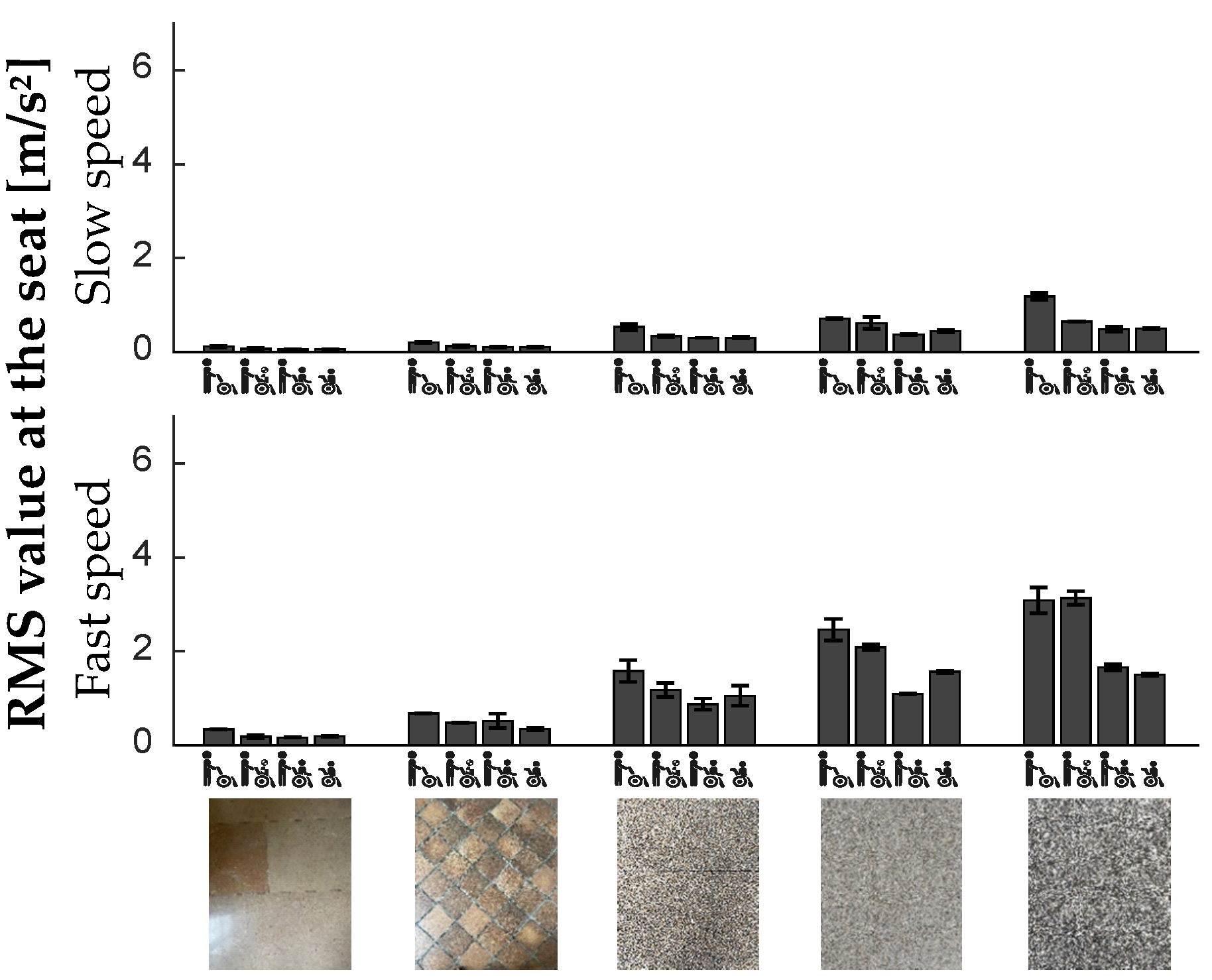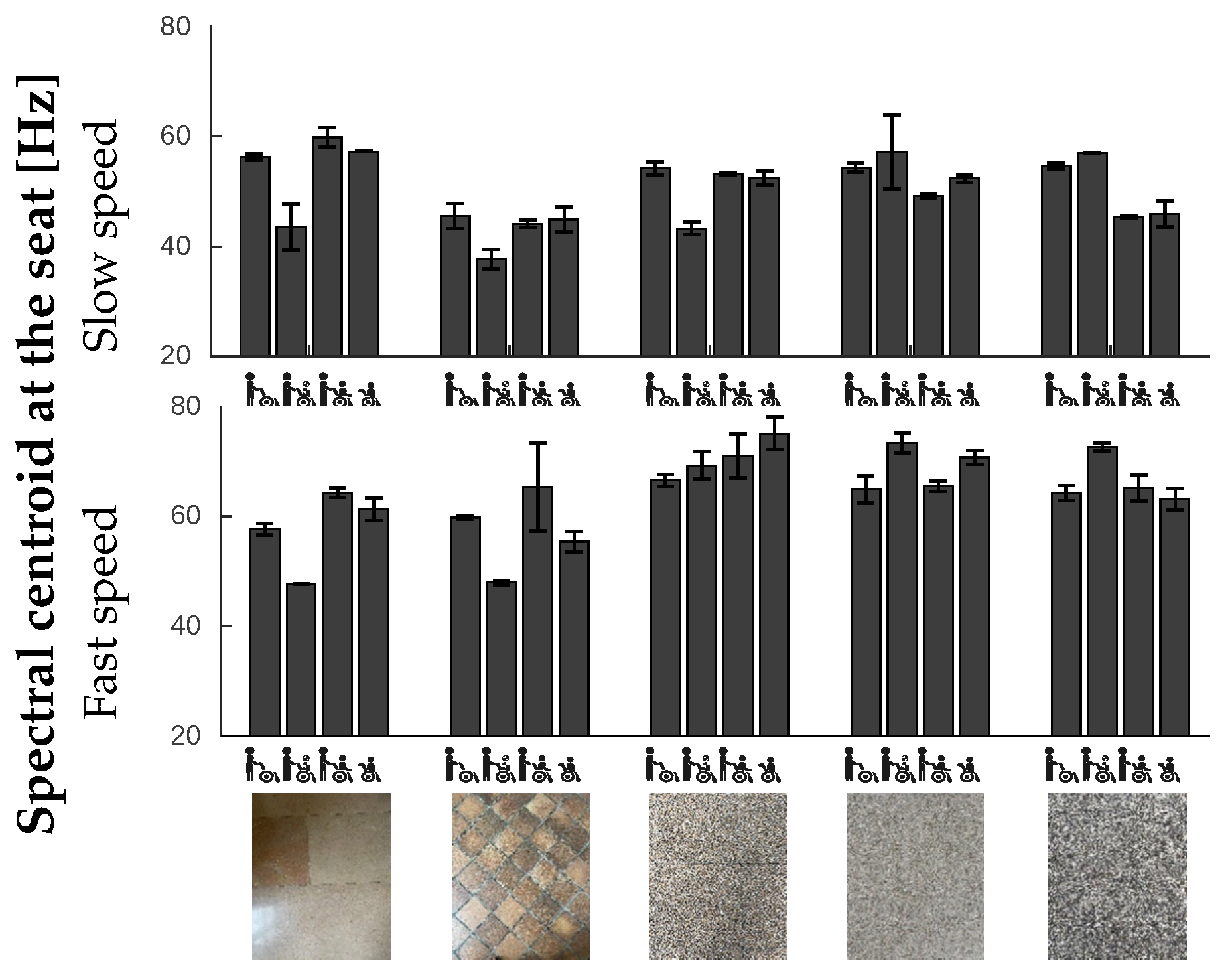

| f (Hz) | (%) |
|---|---|
| 17.8 | 5.7 |
| 27.8 | 5.6 |
| 31.6 | 3.2 |
| 41.22 | 5.5 |
| 49.9 | 2.9 |
| 55.1 | 3.5 |
| 67.7 | 5.9 |
| 71 | 3.1 |
 | [0–10] Hz | [10–20] Hz | [20–30] Hz | [30–40] Hz | [40–50] Hz | [50–60] Hz | [60–70] Hz | [70–80] Hz | |||||||||
|---|---|---|---|---|---|---|---|---|---|---|---|---|---|---|---|---|---|
| f | f | f | f | f | f | f | f | ||||||||||
| (Hz) | (%) | (Hz) | (%) | (Hz) | (%) | (Hz) | (%) | (Hz) | (%) | (Hz) | (%) | (Hz) | (%) | (Hz) | (%) | ||
 | S | 9.7 | 0.8 | 18.8 | 1.3 | 49.7 | 1.6 | 77.4 | 2.2 | ||||||||
| S | 10.6 | 1.1 | 22.6 | 1.4 | 69.2 | 1.5 | |||||||||||
 | S | 10.8 | 0.9 | 20.5 | 1.0 | 43.8 | 1.0 | 58.7 | 1.0 | ||||||||
| S | 6.2 | 0.7 | 16.7 | 0.7 | 48.6 | 0.9 | |||||||||||
 | S | 6.9 | 0.7 | 15.1 | 1.0 | 20.8 | 1.2 | 43.6 | 1.2 | 75.4 | 1.6 | ||||||
| S | 5.0 | 1.2 | 24.4 | 1.3 | 46.7 | 1.4 | 68.7 | 1.4 | 75.1 | 1.6 | |||||||
 | S | 12.3 | 1.3 | 20.7 | 1.4 | 40.2 | 1.6 | 60.7 | 1.7 | 78.1 | 1.9 | ||||||
| S | 5.4 | 2.7 | 70.4 | 2.9 | |||||||||||||
 | S | 26.8 | 1.9 | 41.6 | 2.2 | ||||||||||||
| S | 9.6 | 1.2 | 44.6 | 1.8 | 76.2 | 2.0 | |||||||||||
 | [0–10] Hz | [10–20] Hz | [20–30] Hz | [30–40] Hz | [40–50] Hz | [50–60] Hz | [60–70] Hz | [70–80] Hz | |||||||||
|---|---|---|---|---|---|---|---|---|---|---|---|---|---|---|---|---|---|
| f | f | f | f | f | f | f | f | ||||||||||
| (Hz) | (%) | (Hz) | (%) | (Hz) | (%) | (Hz) | (%) | (Hz) | (%) | (Hz) | (%) | (Hz) | (%) | (Hz) | (%) | ||
 | S | 6.5 | 1.8 | 12.1 | 2.0 | 23.6 | 2.1 | ||||||||||
| S | 24.1 | 1.9 | |||||||||||||||
 | S | 11.3 | 2.0 | 23.8 | 2.3 | ||||||||||||
| S | 23.5 | 0.7 | 72.1 | 0.7 | |||||||||||||
 | S | 7.8 | 0.5 | 19.6 | 0.6 | 63.3 | 0.6 | 79.1 | 0.7 | ||||||||
| S | 8.4 | 0.5 | 28.4 | 0.7 | 56.9 | 0.7 | 60.1 | 0.7 | 73.9 | 0.8 | |||||||
 | S | 17.7 | 0.6 | 27.7 | 0.6 | 52.1 | 1.1 | 68.1 | 1.2 | ||||||||
| S | 29.2 | 0.5 | 43.2 | 0.5 | 67.9 | 0.5 | |||||||||||
 | S | 15.5 | 1.0 | 25.0 | 1.0 | 59.8 | 1.1 | ||||||||||
| S | 29.2 | 0.6 | |||||||||||||||
 | [0–10] Hz | [10–20] Hz | [20–30] Hz | [30–40] Hz | [40–50] Hz | [50–60] Hz | [60–70] Hz | [70–80] Hz | |||||||||
|---|---|---|---|---|---|---|---|---|---|---|---|---|---|---|---|---|---|
| f | f | f | f | f | f | f | f | ||||||||||
| (Hz) | (%) | (Hz) | (%) | (Hz) | (%) | (Hz) | (%) | (Hz) | (%) | (Hz) | (%) | (Hz) | (%) | (Hz) | (%) | ||
 | S | 16.9 | 0.7 | 37.2 | 0.7 | 48.5 | 0.8 | ||||||||||
| S | 42.6 | 0.5 | 65.5 | 0.5 | 76.0 | 0.7 | |||||||||||
 | S | 21.7 | 0.8 | 38.6 | 1.0 | ||||||||||||
| S | 21.8 | 0.7 | 36.6 | 0.8 | 66.1 | 0.9 | |||||||||||
 | S | 14.2 | 0.8 | 23.1 | 0.9 | 28.0 | 0.9 | 41.6 | 1.1 | 62.0 | 1.4 | 76.4 | 2.2 | ||||
| 47.9 | 1.2 | ||||||||||||||||
| S | 34.0 | 1.0 | 47.9 | 1.1 | 62.7 | 1.2 | |||||||||||
 | S | 24.1 | 0.8 | 43.5 | 1.1 | 64.2 | 1.2 | 77.6 | 1.3 | ||||||||
| S | 16.3 | 0.4 | 35.2 | 0.5 | 61.2 | 0.5 | |||||||||||
 | S | 16.2 | 0.8 | 38.7 | 0.9 | 54.2 | 1.1 | 68.3 | 1.1 | ||||||||
| S | 40.0 | 0.7 | 44.6 | 0.7 | 52.3 | 0.7 | 55.9 | 0.8 | |||||||||
 | [0–10] Hz | [10–20] Hz | [20–30] Hz | [30–40] Hz | [40–50] Hz | [50–60] Hz | [60–70] Hz | [70–80] Hz | |||||||||
|---|---|---|---|---|---|---|---|---|---|---|---|---|---|---|---|---|---|
| f | f | f | f | f | f | f | f | ||||||||||
| (Hz) | (%) | (Hz) | (%) | (Hz) | (%) | (Hz) | (%) | (Hz) | (%) | (Hz) | (%) | (Hz) | (%) | (Hz) | (%) | ||
 | S | 43.3 | 0.5 | ||||||||||||||
| S | 17.6 | 0.8 | 42.5 | 0.8 | 66.7 | 0.9 | 78.7 | 1.0 | |||||||||
| 46.1 | 0.9 | ||||||||||||||||
 | S | 18.3 | 0.8 | 30.5 | 0.8 | 45.1 | 1.0 | 74.4 | 1.4 | ||||||||
| S | 34.6 | 0.6 | 42.8 | 0.7 | |||||||||||||
| 48.0 | 0.7 | ||||||||||||||||
 | S | 19.8 | 0.9 | 38.7 | 0.9 | 44.2 | 1.0 | 52.4 | 1.0 | 63.8 | 1.1 | ||||||
| S | 32.7 | 0.8 | 44.6 | 0.8 | 59.7 | 0.8 | 76.0 | 0.8 | |||||||||
 | S | 17.4 | 1.1 | 27.7 | 1.2 | 40.8 | 1.2 | 64.4 | 1.4 | ||||||||
| S | 38.9 | 2.2 | |||||||||||||||
 | S | 24.8 | 1.0 | 37.0 | 1.2 | 58.2 | 1.7 | 73.5 | 2.3 | ||||||||
| S | 62.0 | 0.8 | 75.1 | 0.8 | |||||||||||||
Disclaimer/Publisher’s Note: The statements, opinions and data contained in all publications are solely those of the individual author(s) and contributor(s) and not of MDPI and/or the editor(s). MDPI and/or the editor(s) disclaim responsibility for any injury to people or property resulting from any ideas, methods, instructions or products referred to in the content. |
© 2023 by the authors. Licensee MDPI, Basel, Switzerland. This article is an open access article distributed under the terms and conditions of the Creative Commons Attribution (CC BY) license (https://creativecommons.org/licenses/by/4.0/).
Share and Cite
Larivière, O.; Chadefaux, D.; Sauret, C.; Thoreux, P. Vibration Response of Manual Wheelchairs According to Loads, Propulsion Methods, Speeds, and Ground Floor Types. Vibration 2023, 6, 762-776. https://doi.org/10.3390/vibration6040047
Larivière O, Chadefaux D, Sauret C, Thoreux P. Vibration Response of Manual Wheelchairs According to Loads, Propulsion Methods, Speeds, and Ground Floor Types. Vibration. 2023; 6(4):762-776. https://doi.org/10.3390/vibration6040047
Chicago/Turabian StyleLarivière, Ophélie, Delphine Chadefaux, Christophe Sauret, and Patricia Thoreux. 2023. "Vibration Response of Manual Wheelchairs According to Loads, Propulsion Methods, Speeds, and Ground Floor Types" Vibration 6, no. 4: 762-776. https://doi.org/10.3390/vibration6040047
APA StyleLarivière, O., Chadefaux, D., Sauret, C., & Thoreux, P. (2023). Vibration Response of Manual Wheelchairs According to Loads, Propulsion Methods, Speeds, and Ground Floor Types. Vibration, 6(4), 762-776. https://doi.org/10.3390/vibration6040047