Abstract
This paper explores the modeling and simulation of an innovative double-damper suspension system, evaluating its effectiveness through different test scenarios. The double damper integrates two individual dampers into a unified assembly. The modeling process involves representing the damper as two distinct dampers and a body block, accounting for the additional degree of freedom introduced by combining the two dampers. Simulink/MATLAB is employed for modeling the pressure, discharge, and force equations of the damper. A simplified quarter-car model is designed to conduct simulations for different road profiles, evaluating the efficacy of this double-damper model. The reduced-order modeling approach, suitable for complex systems like dampers, is utilized. Dedicated mathematical models are utilized to examine both single- and double-damper configurations, with the resulting non-linear equations solved using Newton’s iterative method. The equations derived for the single damper provide the basis for modeling the double-damper system. In this model, two separate dampers, each possessing similar properties, are simulated and considered to be rigidly linked at their connection point. Consequently, it is assumed that a portion of the force and velocity experienced by the lower damper is transmitted to the upper damper, and vice versa. Simulation results demonstrate that the innovative double-damper design outperforms a single passive damper in attenuating the oscillations of both the sprung and unsprung masses. Moreover, this innovative concept offers increased adaptability to balance between ride comfort and road holding, a feature previously limited to passive suspension systems.
1. Introduction
Shock absorbers play a pivotal role in enhancing the ride quality and handling characteristics of vehicles by efficiently dissipating the energy generated during the displacement of suspension springs. Traditionally, shock absorbers are engineered to minimize damping force during compression, thereby reducing the impact of bumps, while enhancing damping force during rebound to dissipate stored energy within the suspension system. This hydraulic process involves the transfer of hydraulic oil between chambers via a network of valves, with damping accomplished through the resistance encountered by the oil as it flows through these valves. Early research in the field, such as Lang’s seminal work in 1977 [1], focused on understanding the dynamics of automotive dampers, particularly at high stroking frequencies. Lang’s pioneering research introduced one of the earliest parametric models for twin-tube automotive dampers, laying the foundation for modeling of dampers performance.
Kim [2] conducted a detailed analysis of a twin-tube damper with an emphasis on its integration into a vehicle’s suspension system in 1993. This model accounted for chamber compliance and fluid compressibility, resulting in a differential equation for the chamber pressures, which was solved using the Runge–Kutta method. Discharge coefficients, determined through experimental methods, were incorporated into the model. By integrating damping characteristics into a quarter-car model, he numerically calculated the frequency response of the sprung mass and the tire deflection.
In 1995, Cafferty, Worden, and Tomlinson [3] introduced an alternative method for characterizing automotive shock absorbers using random excitation tests, building on the restoring force surface (RFS) approach from previous harmonic testing. Despite minor stochastic distortions in the force surfaces, their study demonstrated that random excitation is a viable method for identifying the dynamic properties of shock absorbers, highlighting its advantages and limitations compared to harmonic testing.
Reybrouck [4] developed one of the initial detailed parametric models for a monotube damper in 1994. He identified flow restriction forces through empirical formulas incorporating leak restriction, port restriction, and corrections for spring stiffness. After determining the individual internal forces, an additional empirical formula was utilized to compute the total damping force, and the model could also estimate pressure drops across specific flow restrictions. While the correction factors were grounded in physical principles, their precise values were obtained experimentally. The model exhibited strong correlation with experimental data within the 0.5 to 30 Hz frequency range, provided that hysteresis effects were minimal. However, the implementation of the model is complex due to the numerous correction factors necessary for accurate results. The model did not extensively discuss the causes of hysteresis beyond its frequency dependence. In 1997, Reybrouck refined his model to include a twin-tube damper, offering a more comprehensive explanation of hysteresis [5]. He found that hysteresis was affected not only by oil compressibility but also by the compressibility of gas bubbles transferred from the reserve chamber.
In 1997, Mollica and Youcef-Tuomi [6] demonstrated modeling of a monotube damper using the bond-graph method. Herr et al.’s research in 1999 at Tenneco automotive [7] presented an implicit method for simulating automotive hydraulic dampers or shock absorbers by combining computational fluid dynamics (CFD) with dynamic modeling techniques. Through CFD analysis, the study explores the flow characteristics of various damper components, including flow patterns, discharge coefficients, and pressure distribution. These findings are then integrated into a dynamic damper model to predict damping force accurately. Although the implicit and sophisticated model proposed by Herr et al. offers a comprehensive understanding of damper behavior with high accuracy, its complexity renders it less suitable for direct application in control algorithms. Despite its effectiveness in predicting damper performance, its intricacies may pose challenges for integration into real-time control systems or algorithmic frameworks. Talbott and Starkey’s work in 2002 on gas-charged monotube racing dampers [8], and Rhoades’ development of a parametric model in 2006 [9] focusing on damping forces for Formula SAE racecars have further advanced our understanding of shock absorber behavior through mathematical modeling.
Drawing insights from these foundational works on single-damper modeling, we aim to extend these principles to the modeling of double-damper systems. This extension is crucial for predicting the performance of double-damper configurations, which may offer enhanced performance characteristics.
This paper extends the research carried out at the CenTiRe lab of Virginia Tech, concentrating on an in-depth exploration of the double damper. The main question driving this study is whether the integration of two individual dampers into a unified assembly, known as the double damper, can offer superior performance compared to traditional single-damper setups. Specifically, the paper aims to address the following questions: Can the innovative double-damper design outperform a single passive damper in mitigating oscillations of both the sprung and unsprung masses? What are the potential benefits and challenges associated with double-damper systems? How can the modeling process of the double-damper architecture, encompassing components such as the gas chamber, bleed flow, piston valve flow, leakage flow, and semi-active flow, offer an understanding of its intricate dynamics? This study involves developing a mathematical model to describe damper behavior, as well as assessing the performance of various control algorithms using a shock dynamometer. However, this paper reviews only the modeling process, and the second part has been discussed in a separate article. Our modeling process involves representing the double damper as two individual dampers interconnected by a body block, accommodating the additional degree of freedom introduced by this type of arrangement. The novel double-damper technology, featuring semi-active solenoid valves, promises superior ride quality and enhanced car handling, showcasing notable advantages over single-damper systems. The simulation results, particularly those related to unsprung mass displacements, demonstrate the double damper’s superior capability in mitigating high-frequency oscillations from road input. Moreover, this paper follows the reduced-order modeling approach, which is based on development of the analytical model for efficient assessments. The straightforward nature of the model facilitates the evaluation process, enabling us to gauge control algorithm effectiveness across diverse scenarios. While recognizing that the inherent complexities in certain conditions is challenging, this model can provide meaningful insights into control algorithm performance evaluation.
The concept of the double-damper configuration was first conceived at the CenTiRe Lab in June 2014. Yaswanth Siramdasu and Saied Taheri [10] introduced this concept alongside the development of a quarter-car model with two DoFs. This model was designed to simulate the responses of passive, semi-active, and active suspension systems, incorporating the novel idea of the double damper. Then, Sheetanshu Tyagi conducted further design improvement of the double damper at the same lab in 2016 [11]. This research concluded that the double damper could enhance the comfort and handling of the car, a capability not currently achievable with dampers available in the market. Moreover, Anish Gorantiwar and his team conducted additional research in 2020 [12], performing an experimental investigation to evaluate the efficacy of their newly developed semi-active double damper against a traditional single semi-active damper. The findings of this study demonstrated that the double semi-active damper outperformed commercial single dampers in terms of comfort at a comparable cost. This study extends earlier investigations, enriching the field of semi-active suspension technologies. Employing reduced-order modeling techniques helps simplify these complexities while retaining essential system functional performance. This simplification is particularly advantageous for conducting real-time simulations, designing control algorithms, and deepening overall system understanding. The simplified model provides a framework for optimizing control strategies more efficiently.
2. Research Gaps in Double-Damper Systems
Double-damper systems, despite their promise for applications such as isolation devices and structural vibration control, remain novel for use in vehicle suspension systems and present several unexplored areas. The complex dynamics of these systems, characterized by multi-physical interactions and non-linear behavior, lack reliable modeling methods that accurately capture their dynamic responses, transient behaviors, frequency-dependent damping properties, and stability considerations. Optimal design and control strategies also remain underdeveloped, highlighting the need for effective modeling methods. The reduced-order modeling approach is selected to explore the dynamic behavior of such systems, providing a foundation for optimization and the development of appropriate control algorithms. Further research is needed on experimental validation to address uncertainties in the predictive accuracy and practical applicability of these systems. Practical implementation challenges, including manufacturing complexity, cost-effectiveness, reliability, and integration with existing systems, are inadequately addressed. Additionally, there is a notable absence of comparative analyses of double-damper configurations, designs, and control strategies, which are crucial for understanding their relative advantages and limitations and for guiding future research directions.
3. Double-Damper Architecture
To initiate the analytical model, a comprehensive understanding of the shock absorber physics is crucial. The damper is meticulously engineered to enhance damping characteristics and seamlessly integrate with the vehicle’s suspension system. Its core structure features a cylindrical tube housing the standard internal piston. Upon assembly, the tube is intelligently segmented into four distinct chambers: gas, rebound, bypass, and compression, each serving a specific purpose in optimizing the damper’s functionality. Synthesizing these intricate details is essential in preparing for subsequent modeling stages to accurately capture the double damper’s functional behavior.
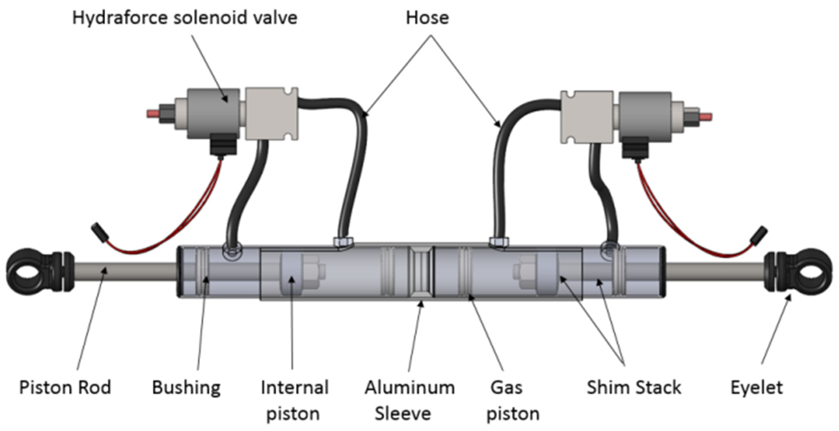
The fundamental components of the double damper are depicted in Figure 1. Consisting of two smaller shocks joined together with an aluminum sleeve, its assembly involves precisely machining the eyelets of the shocks to facilitate secure assembly against each other, fastened in place with a bolt through each. Each individual damper’s construction mirrors that of a single shock, essentially comprising two smaller shocks combined to match the size of a single unit. This design allows for effortless separation of the double damper into two individual dampers, thereby streamlining maintenance and servicing procedures. Additionally, solenoid valves are employed to provide input voltage to the controllers.
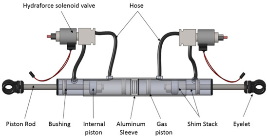
Figure 1.
Double damper elements.
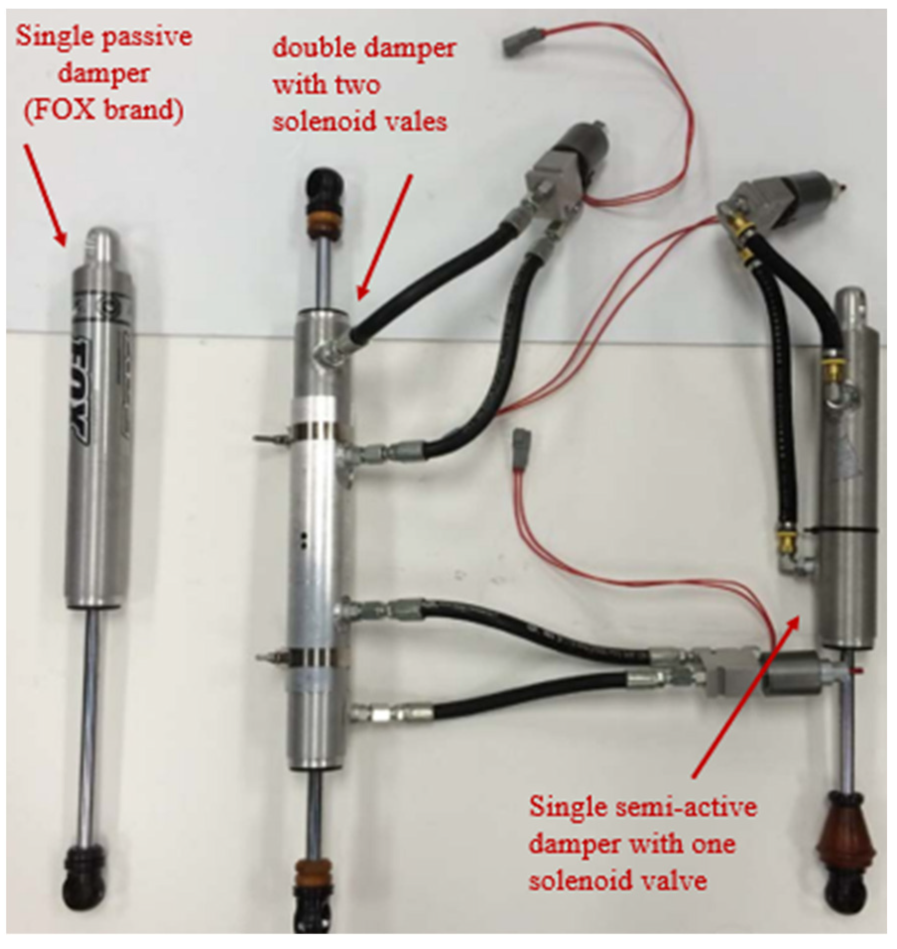
Figure 2 provides a comparison among a passive damper, double damper, and single semi-active damper, arranged from left to right:
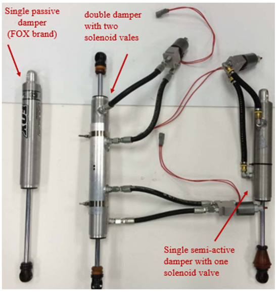
Figure 2.
Dampers used from left to right: passive damper, double damper, single semi-active damper.
At the top of the tube resides the gas chamber, strategically separated from the compression chamber by a floating piston. This piston serves the crucial role of isolating the nitrogen in the gas chamber from the oil in the compression chamber, preventing undesirable interactions between the two components. The compression chamber, situated between the floating piston and the main piston, houses synthetic mineral oil. On the opposite side of the piston, at the bottom end of the tube, is the rebound chamber, mirroring the compression chamber. Both chambers are meticulously filled with synthetic mineral oil to ensure optimal damping performance. The piston, intricately connected to the rod, extends through the rebound chamber and exits the bottom of the tube. To maintain the integrity of the damper’s internal environment, a specially designed seal envelops the rod, preventing oil leakage, minimizing friction, and protecting against external contaminants. The external bypass valve, a critical component placed outside the damper, facilitates the connection between the two chambers. High-pressure hoses seamlessly link the SP10-24 valve to the shock body. During compression, fluid flows through two distinct paths: first through the internal piston, where damping is influenced by orifice area and shim stack stiffness, and second through the external bypass valve. The latter’s damping effect is modulated by the orifice area controlled by the application of voltage. This process is reversed during the rebound stroke, ensuring consistent and controlled damping in both directions. The single semi-active damper is fabricated using these components, maintaining a size like that of the passive damper for equitable testing. This single damper serves as a benchmark for comparison with both the equivalent passive damper and the double-damper configuration. The double damper, a novel configuration featuring two smaller independent shocks held together by an aluminum sleeve, showcases a carefully engineered design. The shocks are seamlessly assembled against each other, held in place by a bolt passing through each, with additional support from an industrial hose clamp securing the shock body to the sleeve. This innovative design not only allows for easy maintenance and service but also enables the separation of the double damper into two individual dampers for independent testing, as demonstrated in subsequent sections.
4. Damper Modeling
Talbott and Rhoades focused on developing mathematical models for high-performing dampers, incorporating various flow paths such as bleed orifice, piston leakage, and shim stack flows, along with considerations for the floating piston and shim stack stiffness characteristics. Their extensively validated models revealed significant insights: negligible compression side pressure variation compared to the rebound side due to the gas charge, effective modeling of valve shim stiffness using stacked thin circular plates, and the critical importance of bleed orifice settings at low speeds, as well as the dominance of shim stack stiffness at high speeds. Equations (1)–(24) presented in this section are based on their research, tailored for application in double-damper semi-active suspension concepts. Building on this foundation, Tyagi and Taheri further advanced this research by dissecting double dampers into individual components, formulating equations for each, and integrating both dampers into a unified model to study dynamic performance. These efforts laid the groundwork for constructing a mathematical model suitable for exploring various controller compatibilities in double-damper systems. The subsequent subsections will detail the specific equations and assumptions used in this modeling process, drawing on their significant contributions.
4.1. Dynamics of Fluid Flow
Understanding the dynamics of fluid flow is essential for analyzing the behavior of such systems across various scenarios. The determination of the total flow rate across the piston necessitates the integration of four distinct flow paths, each playing a critical role in the overall hydraulic behavior. An assumption of the incompressibility of the hydraulic fluid within the damper lies at the core of this analysis, ensuring a consistent density throughout operational phases. Equation (1) serves as the cornerstone for illustrating the total flow rate (in3/sec) during compression or rebound. Here, represents the flow rate through the bleed orifice, responsible for regulating fluid flow during specific operational phases. denotes the flow rate through the piston valve, governing the primary flow path within the damper assembly. accounts for flow rate of leakage past the piston seal, a factor crucial for maintaining operational integrity, and represents the flow rate through the semi-active valve, crucial for modulating damping characteristics.
The total flow rate Q corresponds to the volume of fluid displaced by the rod’s insertion into a segment of the piston. Equation (2) defines the total flow rate (Q′) across a piston section due to rod insertion, with representing the area of the piston on the compression side and denoting the area of the piston on the rod side.
Term represents the time derivative of the displacement x with respect to time t. It signifies the velocity of the rod or piston within the damper assembly. In fluid dynamics, often represents the rate of change of position, indicating how quickly the piston is moving either towards compression or rebound. By simplifying Equation (2) to account for the area change due to rod insertion, Equation (3) is derived:
Further, Equation (4) represents the balance of flow terms, encapsulating the complex interplay between various hydraulic elements within the damper assembly:
To determine individual flow terms, a pressure difference (Δp = pc − pr) between compression and rebound chambers is considered. Bernoulli’s Equation (5) contributes to the modeling of flow through an area (A), incorporating several factors influencing hydraulic performance.
Here, is the density and embodies the steady-state discharge coefficient, a dimensionless parameter influenced by factors including the orifice diameter, Reynolds number, Cauchy number, and thickness-to-length ratio as described in Equation (6). This detailed understanding of fluid-flow dynamics forms the bedrock for precise modeling and optimization of hydraulic systems within the damper assembly. Lang showed that Bernoulli’s equation could be used to model the unsteady flow through constant area passages in a damper:
Lang also found that is constant, as evidenced by a strong correlation with experimental data. Various configurations were tested by adjustable bleed valve settings. The flow was measured experimentally and compared with the mathematical description defined in Equation (5) to determine the coefficient . This equation models the flow through the bleed orifice, which is a component of the total flow. The total flow controls the damping force, as discussed in the other equations in the paper. The bleed flow is modeled as a separate block in Simulink.
4.2. Modeling of Bleed Flow
To characterize bleed flow, Bernoulli’s equation provides a foundation for deriving the discharge through the bleed orifice of the piston, as depicted in Equation (7):
Here, represents the area of the bleed orifice, determined experimentally by measuring the actual area of the damper’s bleed orifice, which can vary. The value of is established through a comparison between simulations and experimental results.
4.3. Modeling of Piston Valve Flow
To facilitate modeling, the flow through the piston valve is divided into two components: the flow through the orifice and the portion of flow that interacts with the shim before exiting. This flow path involves two pressure drops: first, as the fluid exits the compression chamber and enters the piston orifice, denoted as ∆; second, as the fluid traverses the shim stack within the piston, denoted as ∆. The flow rate through the piston orifice follows the same formulation as that of the flow through the bleed orifice, as described by Bernoulli’s Equation (8).
The principle of conservation of mass dictates that the flow through the valves must equal the flow through the piston orifice. This relationship is expressed by Equation (9):
The fluid flow exiting the orifice undergoes a 90-degree turn upon encountering the shim stack. This introduces complexity in modeling the Av term in Equation (9). The effective area of this flow path is equivalent to the area of a cylinder, where the circumference represents the shim’s perimeter and the cylinder’s height corresponds to the deflection of the shim stack, denoted as y:
Equation (10) presents the effective area of the flow path through the shim stack. The term denotes the circumference of the largest shim in the stack, reflecting the total perimeter available for fluid flow. Additionally, the coefficient α in the equation serves as a correction factor, derived from empirical studies such as Talbott’s research [8] on dampers featuring three compression and three rebound holes. For this scenario, α is assumed to be 0.5, indicating that half of the available perimeter is effectively utilized for flow passage. Upon substituting Equation (10) into (9), the complete expression for the flow rate through the piston valve, is derived. This substitution enables us to determine how the effective area, influenced by both shim stack characteristics and the correction factor, contributes to the overall fluid-flow dynamics within the damper assembly:
The subsequent step involves determining the deflection of the shim stack, denoted as y. This critical parameter is achieved by conducting a force balance on the valve assembly. Following this, the discussion will proceed to determine the stiffness of the shim stack, represented by k. Summing forces in the y direction leads to the following equation:
where signifies the area subjected to the valve pressure force, encompassing the effective area of fluid interaction with the shim stack. Meanwhile, denotes the preload spring force, which, in this scenario, is assumed to be negligible due to the piston design of the damper. The momentum force, , is determined based on the conservation-of-momentum principle within the valve assembly. This momentum force arises from the change in fluid direction within the valve, and its calculation is crucial for understanding the dynamic behavior of the system. Equation (13) describes the momentum force within the valve assembly, crucial for understanding the dynamic behavior of the fluid flow:
This force is determined based on the principle of conservation of momentum, which accounts for the change in fluid velocity within the valve. Here, represents the fluid velocity in the y direction after passing through the valve, which is presumed to be zero due to the 90-degree shift in flow velocity. Consequently, the term is expressed in terms of the flow rate and the effective area . This adjustment ensures that the momentum-force equation accurately reflects the fluid dynamics within the valve assembly, resulting in:
and
Combining Equations (14) and (15) into Equation (13), we get
In accordance with Lang’s research, a correction factor was incorporated into the momentum force equation to accommodate the non-zero velocity of the flow in the y direction, validated by comparing actual and predicted momentum forces. The momentum force coefficient, , was determined to be 0.3. Implementing these adjustments to Equations (12) and (16) yields:
4.4. Modeling of Leakage Flow
In the analysis of hydraulic systems, particularly in the context of dampers, accounting for oil leakage is crucial for an accurate representation of system behavior. The leakage flow path primarily addresses the oil seepage occurring between the piston seal and the cylinder walls. Lang (1997) [1] described this phenomenon by modeling it as laminar flow between parallel plates. This simplification is justified by the small distance (<0.004) between the cylinder seal and the walls, which is significantly smaller than the flow length. Here, the flow length corresponds to the height of the piston (b) inside the damper, while represents the diameter of the piston. To characterize the leakage flow mathematically, the Navier–Stokes equation—a fundamental equation in fluid mechanics—was employed. This equation describes the motion of viscous fluid substances and is particularly apt for modeling laminar flow regimes. The leakage flow rate, , through the gap between the piston seal and the cylinder walls can be expressed as:
where denotes the pressure at the cylinder side of the seal, represents the pressure at the rod side of the seal, signifies the height of the piston inside the damper, represents the dynamic viscosity of the fluid, indicates the velocity of the piston, and represents the diameter of the piston.
Equation (18) provides a quantitative expression for the rate of leakage flow, considering the pressure differential across the seal, the geometry of the seal interface, and the velocity of the piston. By incorporating these factors, the model can effectively predict the extent of oil leakage, allowing for informed design decisions and optimization strategies to mitigate potential performance issues associated with excessive leakage.
4.5. Modeling of Semi-Active Flow
The semi-active valve consists of a circular indent that allows for an adjustable change in area from 0 to 0.2 in2. By altering the voltage applied to the solenoid, the fluid flow through the valve can be adjusted. This valve is conceptualized as a circular aperture with a controllable orifice area. The circular hole area is changed in Simulink to vary the area of the valve by changing the voltage supplied depending on the type of the control algorithm. The follow rate through the semi-active valve is depicted in Equation (19):
In many commercial electro-hydraulic dampers, fast-acting solenoid valves are commonly employed. These valves are integrated in various configurations by different inventors. Some designs feature an externally mounted bi-directional solenoid valve, activated by applying voltage. This valve is typically attached to the outer tube of the damper in a twin-tube setup. A customized solenoid rod, resting against spring-loaded shims, facilitates fluid flow when voltage is applied, causing the solenoid to move against the spring. Other dampers utilize a valve assembly where fluid, after passing the solenoid, traverses multiple narrow passages to enhance damping [13].
4.6. Modeling of Gas Chamber
In a monotube damper, the gas chamber accommodates the increase in volume due to the rod’s insertion. Assuming that the oil is incompressible, the gas pressure within the chamber becomes a dynamic variable as a function of the piston displacement. During short operational periods, the gas chamber’s temperature is assumed constant, allowing the use of the ideal gas law to determine the final gas chamber pressure:
With the fluid assumed incompressible, the accelerations of the piston and gas piston are related as:
where represents the acceleration of the gas piston, signifies the cross-sectional area of the piston rod, denotes the cross-sectional area of the gas piston, and indicates the acceleration of the piston. Considering the initial gas pressure and the gas pressure at time t as , Equation (22) can be refined to represent the dynamic evolution of gas pressure with respect to piston displacement:
In this equation, denotes the length of the gas chamber, and represents the displacement of the piston. The gas piston’s force balance yields the compression chamber pressure:
Equation (23) elucidates that the compression chamber pressure remains unaffected by the piston’s velocity, solely contingent upon the piston’s acceleration and displacement and the initial gas pressure.
4.7. Modeling of Damper Force
Once the chamber pressures are discerned, the calculation of damper force assumes paramount importance. Formulating the force balance in the x direction yields:
In Equation (24), F represents the damper shaft force, and denote the compression and rebound pressure forces respectively, and embodies the piston’s frictional force. The frictional force is typically derived from dynamometer measurements conducted at extremely low speeds, where pressure forces are negligible. Acceleration serves as a known input for the lower damper, while its computation is requisite for the upper damper. Pressure forces are computed leveraging the equations elucidated preceding this section. The mass of the piston , encompassing the piston, rod, needle valves, and spherical bearings, can be directly quantified through measurement. Maintaining the gas pressure at a constant 200 psi across all tests, the sole remaining unknown pertains to the damper force, thereby facilitating its determination through the established framework.
For further clarity, all the flow equations are essentially used to determine the force in Equation (24). The area terms are design parameters of the damper, while the pressure terms are calculated from the various flow equations. The dynamic behavior of the damper depends on the velocity and acceleration terms, which are inputs to the damper model.
5. Modeling Double Damper on Simulink
Modeling the double damper in Simulink involved creating separate models for both the single- and double-damper configurations. The behavior of these dampers is governed by non-linear differential equations, which required a robust numerical method for solving. To achieve this, Newton’s iterative method was employed, a technique well-suited for handling non-linear systems. The process began with an initial guess for the displacement and velocity of the damper. With these initial values, the Jacobian matrix, which contains partial derivatives of the system’s equations with respect to the variables, was calculated. This matrix is crucial as it helps linearize the non-linear equations around the current guess, making them easier to solve. Next, the non-linear functions representing the damper’s dynamics were evaluated at the current guess. These functions describe how the damper’s displacement and velocity change over time under various forces. Using the evaluated functions and the Jacobian matrix, an update step was computed. This step involves solving a linear system to find the change needed in the guess to move closer to the true solution. The new guess for displacement and velocity was obtained by adding this update step to the old guess. This iterative process of evaluating the functions, computing the Jacobian, finding the update step, and refining the guess was repeated until the changes became negligibly small, indicating that the solution had converged. To ensure the simulations were both precise and efficient, the step sizes used in the iterative process were dynamically adjusted. This dynamic adjustment was crucial in capturing the transient behaviors accurately without imposing an excessive computational burden. This approach to solving the non-linear equations was adapted from the techniques outlined in Numerical Methods for Engineers and Scientists by Hoffman. [14] This methodology provided a structured framework for addressing complex non-linear systems using iterative techniques, ensuring that the model represented the real-world dynamics of the double damper. By employing this method, the Simulink model effectively captured the complex interactions within the double damper, offering reliable predictions of its performance under various operating conditions.
In the modeling process, the single damper is modeled in Simulink based on the derived damper equations, comprising three main blocks: compression, rebound, and final values.
In fact, the double-damper system incorporates two blocks, one for each of the individual damper components, while the single-damper system uses just one of these blocks. In the rebound block, the values are essentially zero when the velocity is positive. Although this could be managed using an ‘if’ block or equivalent conditional logic, modeling it separately simplifies troubleshooting if the results do not align with expectations. The input block receives values derived from a quarter-car model. In this model, the road input is the sole input to the entire system, driving the dynamic response of the damper.
Subsequently, the final-values block consolidates results from individual compression and rebound blocks, plotting them against velocity to generate final plots for the single semi-active damper. Additionally, a quarter-car block is constructed to incorporate sprung and unsprung masses, along with tire stiffness and damping coefficients, as detailed in [15]. Although the quarter-car model, with assumed unsprung, and values, is not correlated with real-time data due to testing limitations to the shock-dynamometer testbed, it provided a foundational step for further design iterations.
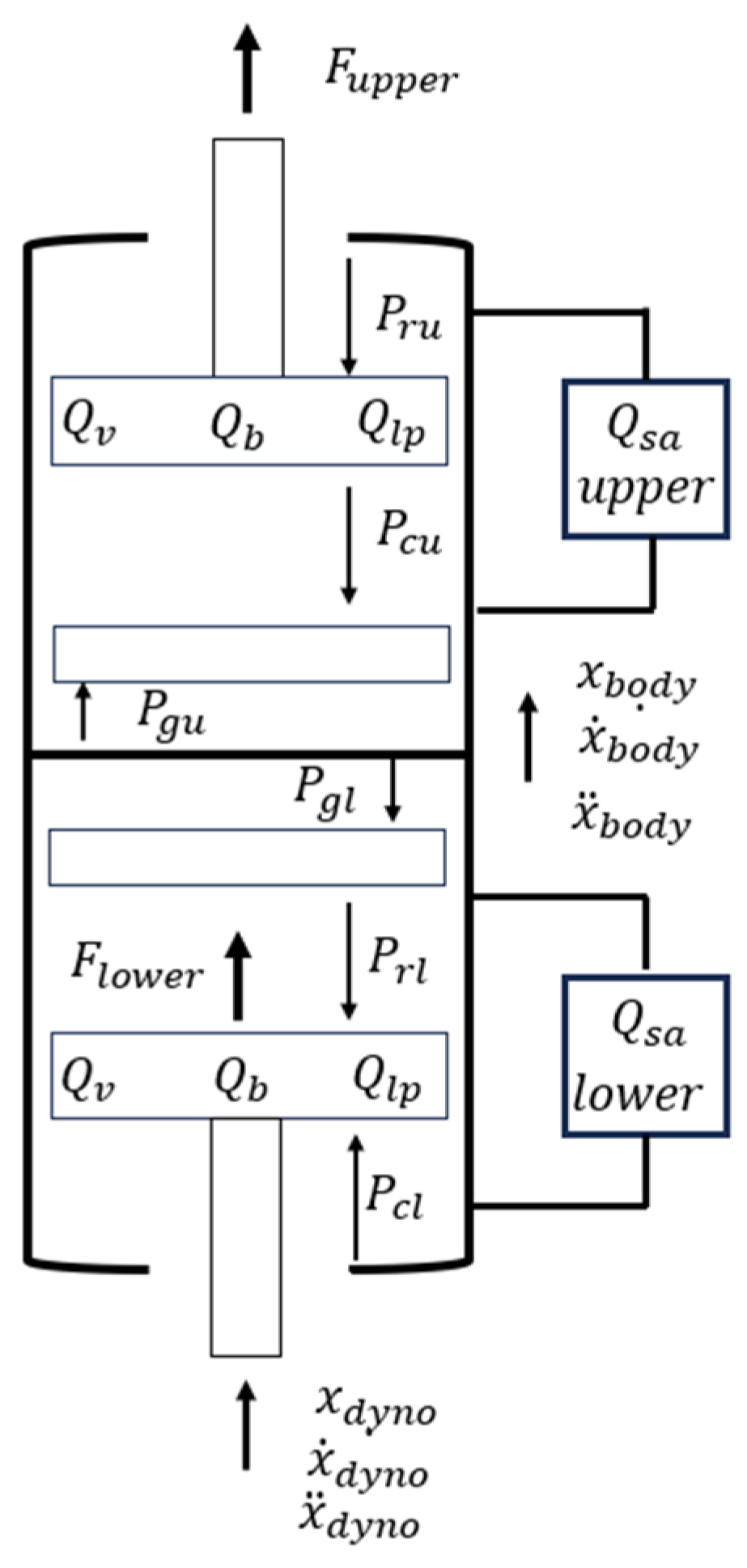
The double damper is then modeled in Simulink as two separate damper blocks, with a third ‘body’ block connecting them. The body block facilitates transmission of force and velocity between the lower and upper dampers. Both dampers were modeled similarly, employing pressure and discharge equations discussed earlier. The free-body diagram of the double damper is illustrated in Figure 3. Additionally, another quarter-car model block is implemented to account for sprung and unsprung masses, acting as an excitation source for the lower damper. A portion of the damper force is transmitted to the body block, serving as input for the upper damper. The disparity in pressures within the chambers, coupled with varied sprung and unsprung accelerations, contributes to both the lower and upper forces.
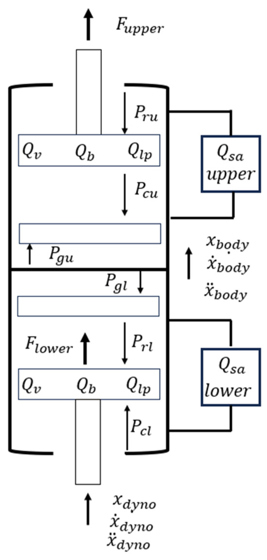
Figure 3.
Free-body diagram of the double damper [11].
Parameters that are used for the damper modeling and functional simulation using Simulink have been presented in Table 1. While a variety of control algorithms have been explored and utilized to optimize the performance of the double-damper system, it is important to note that the specific details and results of these algorithm evaluations are not presented in this paper. Instead, the focus of this study lies on the modeling and simulation aspects of the double-damper system, as well as the comparison of its performance with a traditional single-damper setup.

Table 1.
Parameters used for the damper modeling on Simulink.
6. Simulation Results
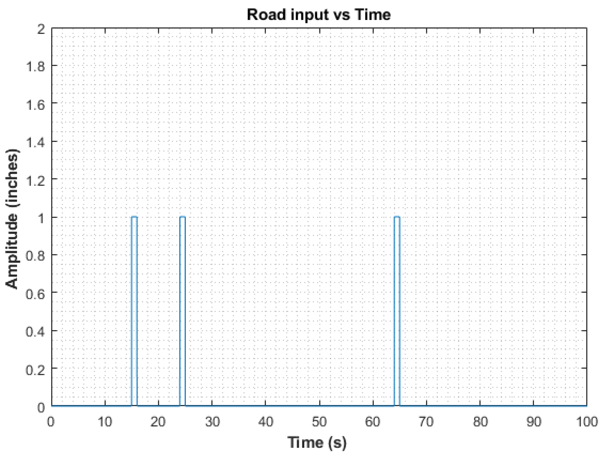
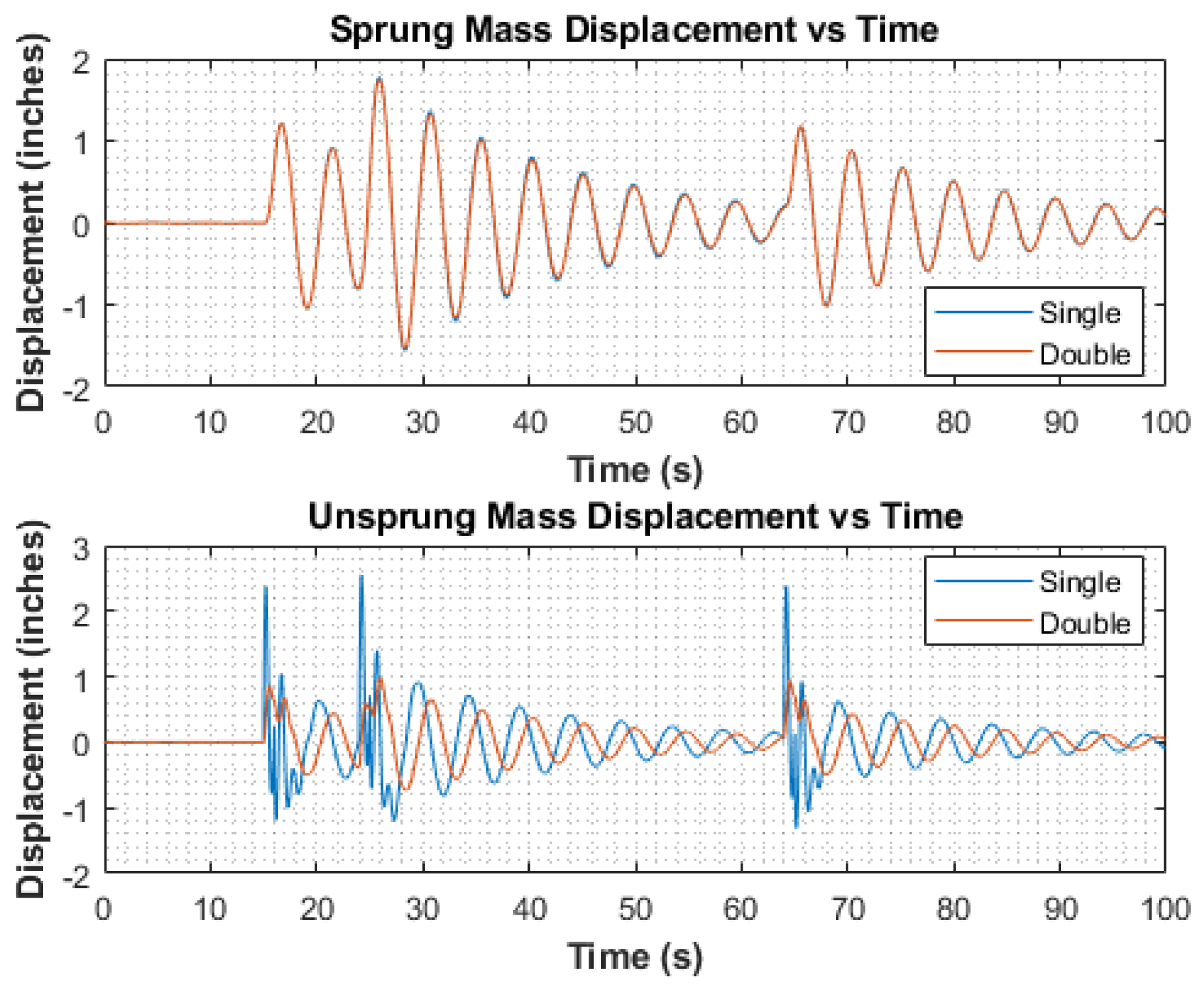
The simulation is performed to compare single- and double-damper models in terms of unsprung and sprung mass displacements and accelerations. Figure 4 illustrates the road input, characterized by three step inputs occurring at time intervals of 15, 24, and 64 s, thereby generating a sequence of bumps in the damper system’s response. These step inputs were strategically positioned within the road input vector to emulate real-world scenarios. Analysis of the simulation results revealed a noticeable reduction in the unsprung mass displacement for the double-damper configuration compared to its single-damper counterpart. Figure 5 depicts the unsprung mass oscillations, illustrating that the single damper exhibits greater amplitude oscillations compared to the double damper. The observed lag in the double-damper response can be attributed to the delay in additional damping force being applied.
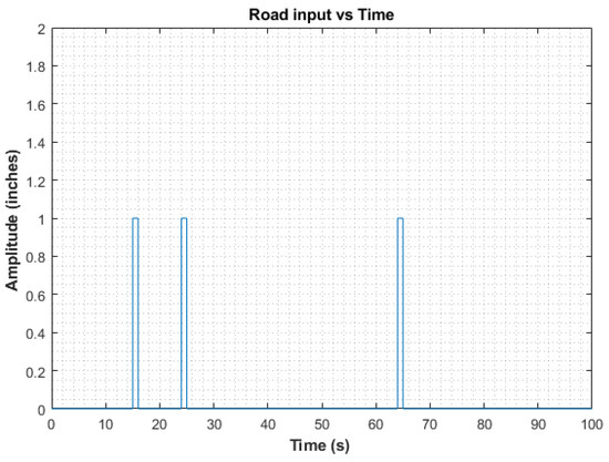
Figure 4.
Road input with multiple impulse profile.
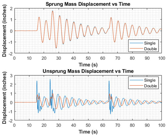
Figure 5.
Comparisons between unsprung and sprung mass displacement for two dampers due to multiple impulse road profile.
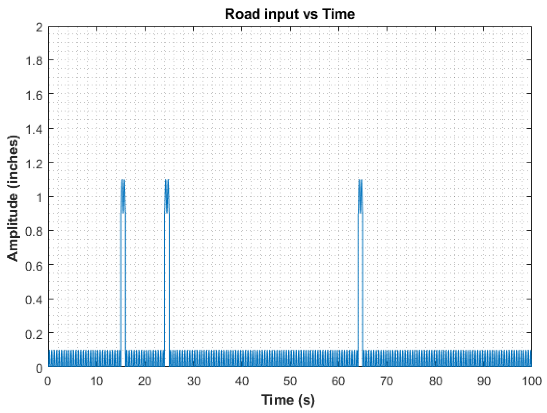
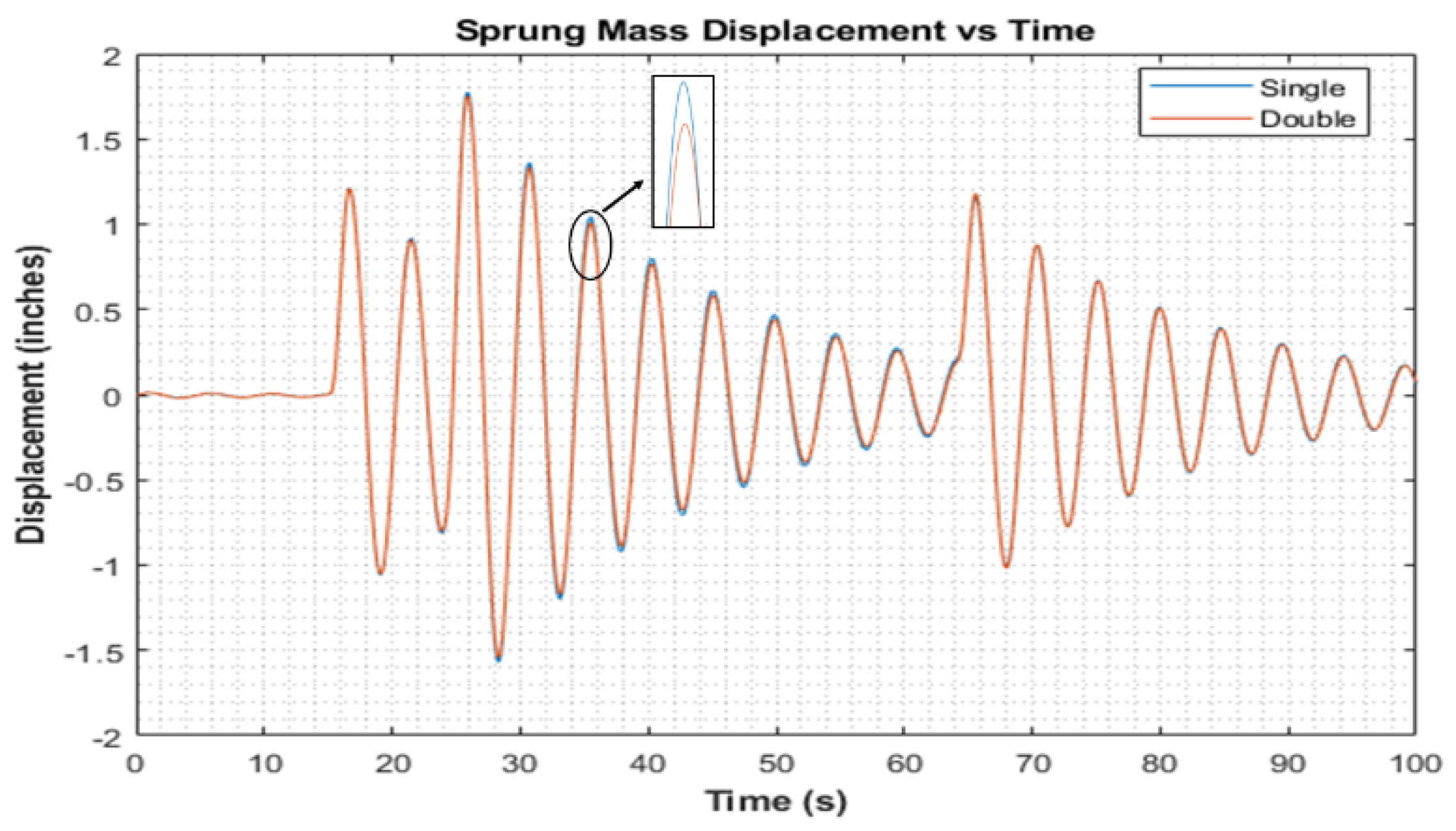
To further explore damper behavior under continuously fluctuating road conditions, a sinusoidal wave with an amplitude of 0.1 inches and a frequency of 25 Hz was introduced into the existing road input, as depicted in Figure 6. The simulation results, particularly regarding unsprung mass displacements, highlight the double damper’s effectiveness in attenuating high-frequency sine oscillations in the road input compared to the single semi-active damper employing the same control logic, as evidenced in Figure 7. Furthermore, the double damper exhibits superior damping of sprung-mass oscillations compared to the single damper, albeit with a less pronounced difference. Notably, both dampers demonstrate nearly identical steady-state behavior, underscoring the efficacy of the double-damper configuration in damping oscillations across the system. Additionally, the double damper provides better damping for the oscillations of the sprung mass compared to the single damper. Although the difference is not as significant, both dampers show nearly identical behavior once they reach a steady state.

Figure 6.
Road input including impulses and sinusoidal wave.
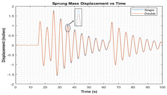
Figure 7.
Comparison between sprung mass displacement of two damper concepts, single and double dampers.
However, due to certain constraints, it was not feasible to conduct the tests and simulations under identical conditions. The primary challenges we faced were equipment limitations and safety concerns. These constraints made it impractical to replicate the exact conditions for both numerical and experimental analyses. Despite these limitations, we carefully designed our study to provide meaningful comparisons between single- and double-damper systems. Both test and simulation environments, although not identical, were consistent within their respective categories, allowing for valid comparative analysis. Our goal was to highlight the relative performance improvements and differences between the two systems rather than an absolute validation under identical conditions. The mathematical model was employed for control algorithm adaptation, which is not in the scope of this paper.
7. Shock Dynamometer Testing Results
The experimental setup for damper testing depicted in Figure 8 provided a platform to evaluate the performance of the dampers. The shock dynamometer testing is conducted within the frequency range of 0.25 Hz to 3 Hz, effectively capturing a spectrum of vehicle dynamics including yaw, roll, and pitch dynamics [16]. Both the single and double dampers are subjected to testing at a suspension velocity of 2 in/sec on the shock dynamometer. This testbed machine facilitates systematic evaluation of the dampers’ responses across a range of velocities, enabling detailed analysis of their force-vs.-velocity characteristics. As presented in reference [15], by subjecting the dampers to varying velocities, the testing captures their performance under dynamic conditions representative of real-world driving scenarios. The force-vs.-velocity graphs illustrate the force buildup characteristics with varying velocity.
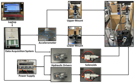
Figure 8.
Damper experimental setup.
These force-vs.-velocity graphs provide valuable insights into the behavior of the dampers under different loading conditions and velocities. These plots illustrate the force buildup characteristics exhibited by the dampers as the velocity varied, offering a comprehensive understanding of their damping capabilities across a wide range of operating conditions.
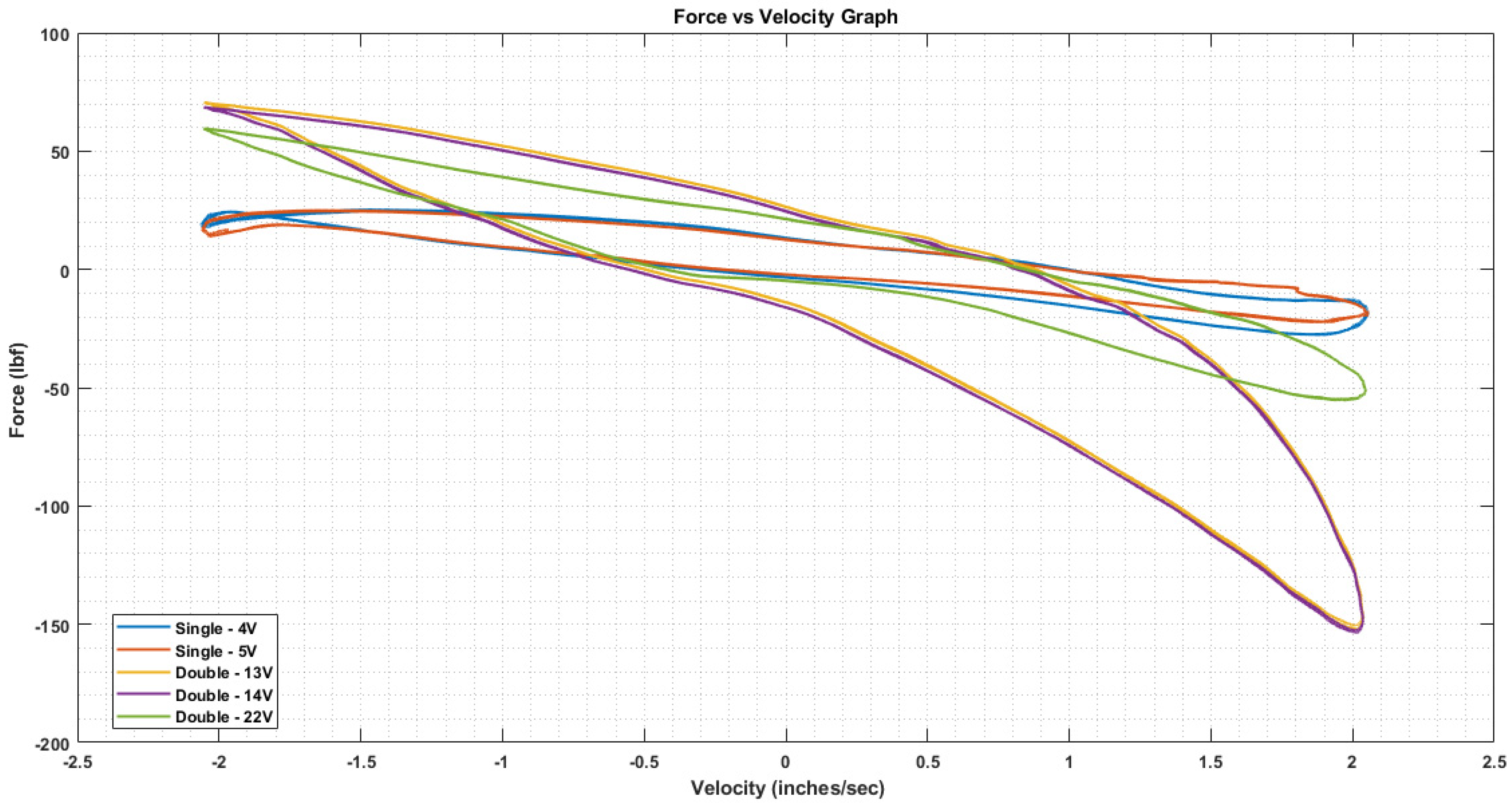
Figure 9 displays the force-vs.-velocity graph for both single and double dampers tested at different combinations of voltages, showcasing their behavior. The different combinations of damping achievable by supplying various voltages to the upper and lower damper, along with the adjustable behavior of the shim stack, allow for fine-tuning of the dynamic response of the damper. Specifically, varying the input voltage or current to a semi-active damper alters its performance characteristics. This is because semi-active dampers use electromagnetic or magnetorheological principles to modulate the damping force in real time based on the supplied electrical input. By adjusting the voltage, the viscosity of the damping fluid or the force exerted by the damper can be controlled, resulting in different damping rates. This ability to precisely control the damping force is crucial for optimizing the ride comfort and handling performance of the vehicle. Therefore, the choice of supplied voltages is determined based on the desired dynamic response and performance characteristics of the damper in various operating conditions. When voltage is applied, the solenoid moves upward against the spring, permitting fluid to pass through. Damping through the internal piston relies on orifice area and shim-stack stiffness, while flow through the bypass valve is regulated by orifice size controlled by voltage application. Two 12 V power supply was utilized to maintain the voltage, with the shock receiving input from 0 to 5 V for the single and 22 V for the double damper.
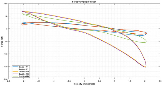
Figure 9.
Force vs. velocity for the single and double damper tested with different combinations of voltages at 2 in/sec.
Fundamentally, rebound forces are notably higher in all cases due to asymmetrical shim stacks. Across all configurations, the double damper exhibits greater force in both compression and rebound compared to the single damper. Even the 22nd configuration of the double damper, though less stiff than the 13th and 14th configurations, produces more damping force than the single damper.
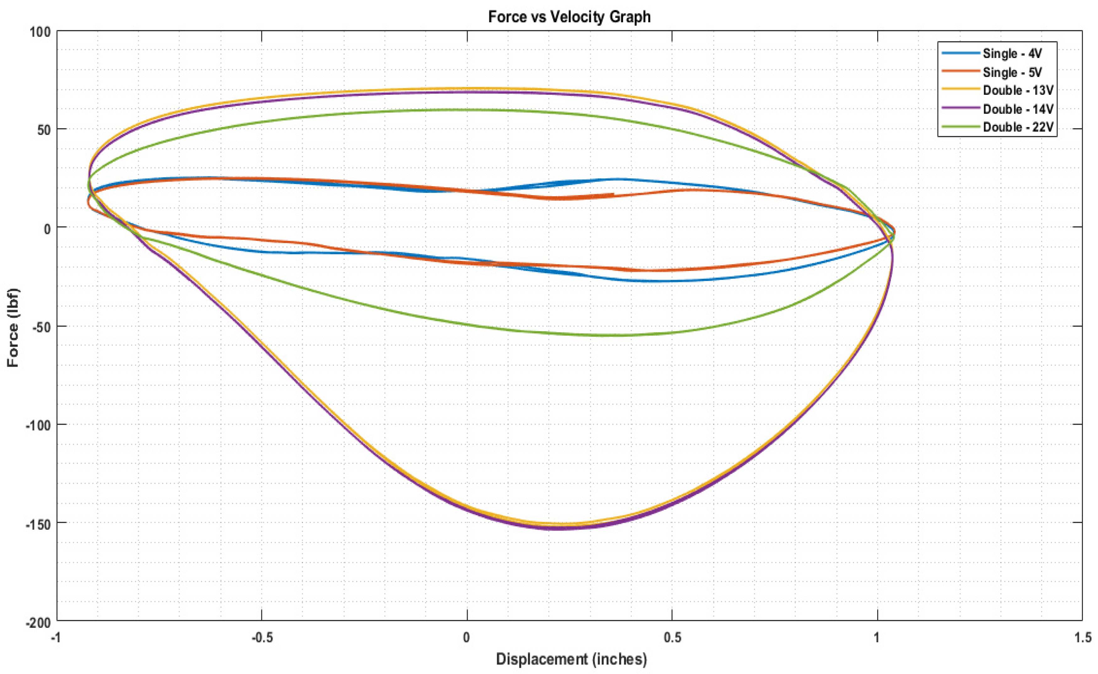
Furthermore, as illustrated in Figure 10, the double damper generates greater force than the single damper for similar suspension deflection. The higher rebound force compared to compression aligns with simulation results, indicating an improvement in ride quality with the double damper in the suspension system.
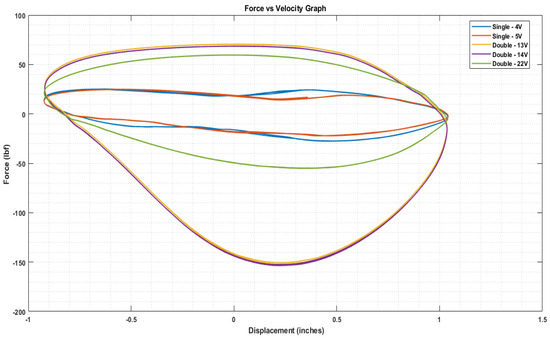
Figure 10.
Force vs. displacement for the single and double damper tested with various voltage combinations at 2 in/sec.
Another observation from Figure 9 and Figure 10 is that for the single damper, the damping forces decrease progressively with increasing voltage, ranging from fully closed (0 V) to fully open (5 V/1.2 A), resulting in varied rebound forces due to asymmetrical shim stacks. Conversely, the double damper, operating with identical upper and lower solenoid voltages, behaves passively in the fully closed scenario (0 V), with flow through the bleed orifice and shim stacks, leading to the highest compression and rebound forces. Beyond the 22 V configuration, the double damper exhibits a shift in behavior, transitioning from a digressive to a progressive nature, influenced by factors like increased frictional forces and constant flow through the semi-active orifices at low speeds. This adaptability in damper response holds potential for enhancing ride comfort in SUVs across diverse road conditions.
8. Conclusions
This paper presents the results of a study on the modeling, simulation, and performance evaluation of a novel double-damper system against a traditional single-damper configuration using Simulink/MATLAB. The modeling process involved representing the double damper as two individual dampers interconnected with a body block, thus accommodating the additional degree of freedom introduced by the integration of two dampers. Leveraging the reduced-order modeling (ROM) approach proved apt for capturing the complexities inherent in damper systems, enabling the application of equations to both passive and double-damper configurations.
Simulations were conducted across various road profiles employing a simplified quarter-car model. The results demonstrate the superior performance of the innovative double-damper design in mitigating oscillations of both the sprung and unsprung masses, compared to a single damper. Furthermore, the paper also focuses on the pros and cons associated with the double-damper system. Highlighted benefits of the double-damper system include its cost-effectiveness, simplicity, versatility across vehicle types, enhanced reliability, ease of integration, and its ability to strike a balanced combination of ride comfort and handling performance by having two independent damping characteristics. However, challenges such as higher length constraints for compact cars, friction dynamics with dual cylinders and pistons, and the need for extensive testing and market validation are duly acknowledged. Thorough modeling of the double-damper architecture, encompassing components such as the gas chamber, bleed flow, piston valve flow, leakage flow, and semi-active flow, provides invaluable insights into its intricate dynamics. Special attention is given to modeling the gas chamber, accounting for the incompressibility of oil and utilizing the ideal gas law to determine gas pressure. Simulation results showed significant improvements in unsprung mass displacement for the double damper compared to the single damper, especially under impulse and sinusoidal road inputs.
Shock dynamometer testing demonstrates the superior performance of the double damper, showcasing increased force in both compression and rebound compared to the single damper. The force-vs.-velocity and force-vs.-displacement graphs highlight the enhanced damping capabilities of the double damper. The progressive nature of the damper depends on factors such as frictional forces and the absence of a shim stack. This flexible characteristic, coupled with its progressive nature and ability to handle greater damping peak loads, makes the double damper suitable for SUVs, where ride comfort is crucial for both on-road and off-road conditions. These conclusions are supported by findings detailed in reference [15]. Additionally, an observed trend suggests that force varies predictably with voltage, with the lowest applied voltage resulting in the highest force output.
Importantly, this modeling approach lays a solid foundation for the analysis of different control algorithms. The straightforward nature of the model facilitates a streamlined evaluation process, enabling researchers to gauge control algorithm effectiveness across diverse scenarios. This study emphasizes the potential of the model to provide meaningful insights into control algorithm performance, making it a valuable tool in the iterative process of algorithm development and refinement. In conclusion, this study not only contributes valuable insights into the potential of the double-damper system for advanced vehicle suspension but also positions itself as an asset for the analysis and optimization of different control algorithms to achieve the best performance.
Author Contributions
Conceptualization, S.S. and S.T.; methodology, S.S.; software, S.S.; validation, S.S., S.T. and B.H.; formal analysis, S.S.; investigation, B.H.; resources, S.T.; data curation, S.S.; writing—original draft preparation, B.H.; writing—review and editing, B.H.; visualization, B.H.; supervision, S.T.; project administration and funding acquisition for prototyping and testing. All authors have read and agreed to the published version of the manuscript.
Funding
This research received no external funding.
Data Availability Statement
The data presented in this study including detail design of the double damper are available on request from S.T. The technical data is not publicly available due to confidentiality.
Conflicts of Interest
The authors declare no conflict of interest.
References
- Lang, H.H. AStudy of the Characteristics of Automotive Hydraulic Dampers at High Stroking Frequencies. Ph.D. Dissertation, The University of Michigan, Ann Arbor, MI, USA, 1977. [Google Scholar]
- Kim, D. Analysis of Hydraulic Shock—Absorber Implementation on the Vehicle Suspension Systems. Master’s Thesis, Seoul National University, Seoul, Republic of Korea, 1993. [Google Scholar]
- Cafferty, S.; Worden, K.; Tomlinson, G. Characterization of Automotive Shock Absorbers Using Random Excitation. Proc. Inst. Mech. Eng. Part D J. Automob. Eng. 1995, 209, 239–248. [Google Scholar] [CrossRef]
- Reybrouck, K.G. A Non Linear Parametric Model of an Automotive Shock Absorber; SAE Technical Paper Series 940869; SAE International: Warrendale, PA, USA, 1994. [Google Scholar]
- Duym, S.W.; Steins, R.; Baron, G.V.; Reybrouck, K.G. Physical Modeling of the Hysteretic Behaviour of Automotive Shock Absorbers; SAE Technical Paper Series 970101; SAE International: Warrendale, PA, USA, 1997. [Google Scholar]
- Mollica, R.; Youcef-Toumi, K. A Nonlinear Dynamic Model of a Monotube Shock Absorber. In Proceedings of the American Control Conference, Albuquerque, NM, USA, 6 June 1997; pp. 704–708. [Google Scholar]
- Herr, F.; Mallin, T.; Lane, J.; Roth, S. A Shock Absorber Model Using CFD Analysis and Easy5; SAE Technical Paper 1999-01-1322; SAE International: Warrendale, PA, USA, 1999. [Google Scholar] [CrossRef]
- Talbott, M.S.; Starkey, J. A Mathematical Model of a Gas-Charged Mono-Tube Racing Damper; SAE International: Warrendale, PA, USA, 2002. [Google Scholar] [CrossRef]
- Rhoades, K.S. Development and Experimental Verification of a Parametric Model of an Automotive Damper. Master’s Thesis, Texas A&M University, College Station, TX, USA, 2006. [Google Scholar]
- Siramdasu, Y.; Taheri, S. A New Semi-Active Suspension System for Vehicle Applications. In Proceedings of the ASME 2017 Dynamic Systems and Control Conference, Tysons, VA, USA, 11–13 October 2017. [Google Scholar]
- Tyagi, S. Development of a Semi-active Suspension System for Lightweight Automobiles. Thesis for Master of Science in Mechanical Engineering, Virginia Polytechnic Institute and State University, Blacksburg, VA, USA, 2016. [Google Scholar]
- Gorantiwar, A.; Nalawade, R.; Nouri, A.; Taheri, S. Experimental Analysis of a Novel Double Damper System with Semi-Active Control. J. Electron. 2020, 9, 1518. [Google Scholar] [CrossRef]
- Reybrouck, K.G.; Schurmans, R.J. Damper with Externally Mounted Semi-Active System. Google Patents US6321888B1, 27 November 2001. [Google Scholar]
- Hoffman, J.D. Numerical Methods for Engineers and Scientists, 2nd ed.; Marcel Dekker, Inc.: New York, NY, USA, 2001. [Google Scholar]
- Shrikanthan, S. Modeling, Development and Experimental Validation of Different Control Strategies for a Double-Damper Semi-Active Suspension System. Dissertation for the degree of Master of Science in Mechanical Engineering, Virginia Polytechnic Institute and State University, Blacksburg, VA, USA, 2024. [Google Scholar]
- Bhanot, N. Artificial Neural Networks Based Modeling and Analysis of Semi-Active Damper System. Ph.D. Thesis, Virginia Polytechnic Institute and State University, Blacksburg, VA, USA, 2017. [Google Scholar]

Disclaimer/Publisher’s Note: The statements, opinions and data contained in all publications are solely those of the individual author(s) and contributor(s) and not of MDPI and/or the editor(s). MDPI and/or the editor(s) disclaim responsibility for any injury to people or property resulting from any ideas, methods, instructions or products referred to in the content. |
© 2024 by the authors. Licensee MDPI, Basel, Switzerland. This article is an open access article distributed under the terms and conditions of the Creative Commons Attribution (CC BY) license (https://creativecommons.org/licenses/by/4.0/).