Abstract
In this study, we introduce progress in intelligent control for reducing structural vibrations. The field of intelligent control for dampening structural vibrations is evolving rapidly, driven by advancements in materials science, AI, and actuator technology. These innovations have led to more efficient, reliable, and adaptable vibration-control systems with applications ranging from civil engineering to aerospace. The use of smart materials has opened new avenues for vibration control of piezoelectric materials. When mechanical stress is applied to these materials, an electric charge response is formed, allowing for precise control over the vibrations. Improved computational models and simulations play crucial roles in the design and testing of vibration-control systems. Finite element analysis helps in accurately predicting the behavior of structures under various loads, thereby aiding in the design of effective vibration-control systems. In our work, we use intelligent control theory to dampen structural vibrations in engineering structures.
1. Introduction
Advancements in intelligent control for dampening structural vibrations have been significant in recent years owing to the incorporation of various innovative technologies and methodologies [1,2,3,4,5]. Many researchers have used active control for vibration suppression. Active control systems use sensors and actuators to dynamically respond to vibrations. Notable advancements include the development of smart materials and structures [6,7,8,9,10,11,12]. The use of smart materials has opened new avenues for vibration control, which generates an electric response parallel to the mechanical stress, enabling precise control over vibrations. Shape-memory alloys (SMAs) can alter their shape along with temperature changes, offering another method for active vibration control and self-healing materials; These repair themselves when damaged, improving the longevity and reliability of vibration-control systems. The use of smart materials has opened new avenues for the vibration control of piezoelectric materials [13,14,15,16,17]. Materials such as these induce an electric charge when mechanical stress increases, permitting precise control over vibrations [18,19,20,21].
Recent advancements in intelligent control for dampening structural vibrations have led to significant technological and methodological innovations. In our work, we used smart materials, such as piezoelectric materials. Piezoelectric materials provide new methods to achieve precise and durable vibration control. Recent advances in wireless communication and networking technologies have facilitated the implementation of sophisticated control strategies using distributed sensor networks, IoT systems, and devices. These innovations enable the real-time monitoring and remote control of processes. Hybrid control systems, which combine active and passive methods, help to optimize effectiveness and energy consumption. Furthermore, advanced computational models such as finite element analysis (FEA) and digital twins are utilized to design and test control systems, and some systems can harvest vibrational energy to power sensors or other devices, thereby enhancing sustainability. These innovations have been applied successfully in various real-world scenarios, such as high-rise buildings, bridges, and aerospace, and have improved structural integrity and performance. The innovation of this study is that sophisticated control approaches were used to restrain oscillations [22,23,24,25,26]. The control techniques that we used checked and introduced uncertainties in the simulation model.
In this paper, we propose innovative methods for suppressing structural oscillations. Our research was initiated with the application of the finite element method (FEM) to piezoelectric structures, laying the groundwork for understanding their dynamic behavior. We then introduced dynamic loads to these structures, which naturally induce oscillations. To address these oscillations, we employed advanced control techniques designed to mitigate and ultimately suppress them.
The success of our approach is demonstrated through the complete suppression of oscillations achieved using sophisticated models specifically developed by the authors. These models not only confirm the effectiveness of our control strategies but also validate the overarching theme and title of our paper. This title reflects the significant progress made in enhancing the precision and reliability of vibration suppression using intelligent control methodologies. In this study, the complete suppression of oscillations is achieved. The carrier is modeled with finite elements, taking into account both mechanical and electrical loading, and using advanced control techniques, complete vibration suppression is achieved. Advanced control techniques are used to achieve this. Infinity and μ-analysis are intelligent control techniques that require advanced algorithms. The oscillations are reduced with the help of these intelligent control techniques.
2. Methodology
2.1. Motion Formulation of Intelligent Structures
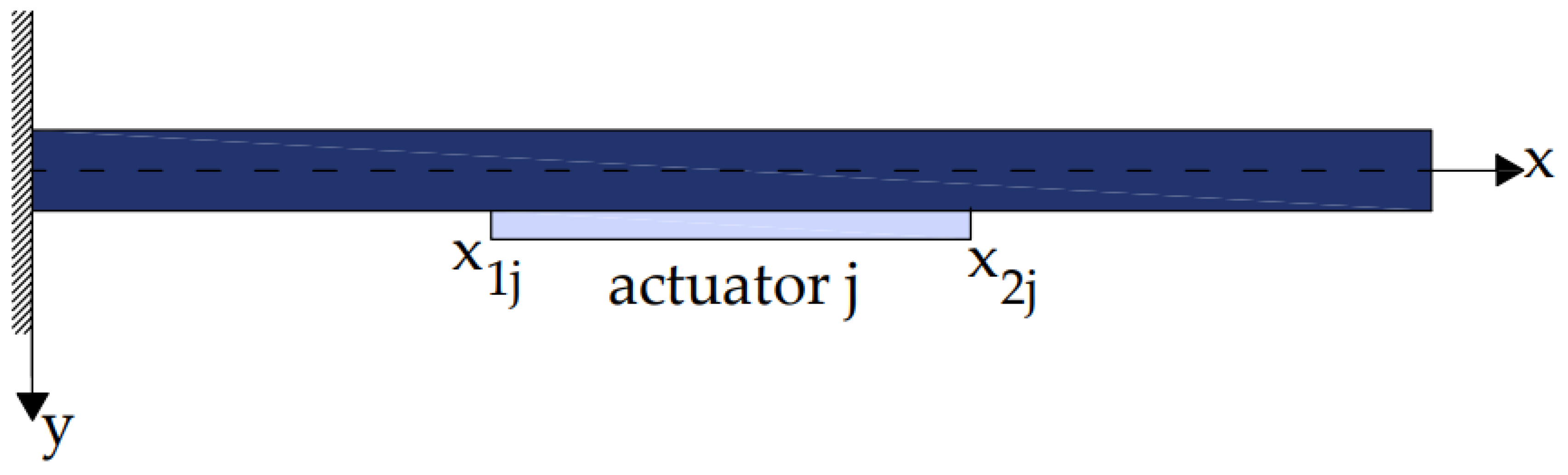
In this study, piezoelectric materials were used as sensors and actuators. In our simulation, we applied co-localized piezoceramic (PZT/G/1195) actuator twin pairs embodied in laminated composite (glass/epoxy and graphite/epoxy) and metallic (aluminum) beams [27,28] (Figure 1). Smart piezoelectric structures are advanced materials and systems that leverage the unique properties of piezoelectric materials to provide intelligent, adaptive, and self-monitoring capabilities. The piezoelectric effect refers to the capacity of a material to generate electric charge when it is mechanically stressed. However, the application of an electric field can distort certain materials. The beam expression for mechanical and electrical loads is given by [19,20,21,22,27]:
fm is the mechanical force ;
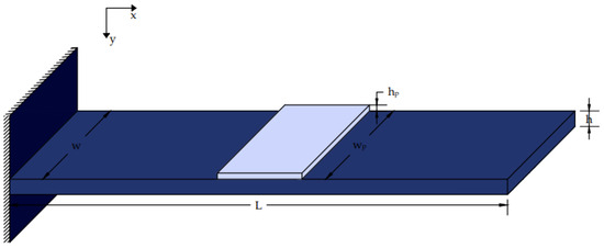
Figure 1.
Beam with a piezoelectric patch installed.
fe is the electrical force;
E is the modulus of elasticity of the beam;
I is the moment of inertia of the beam;
A is the area of the beam;
b is the width of the beam.
A smart beam was equipped with an incorporated piezoelectric actuator (Figure 2) that generates a mechanical load when electrically stimulated, as shown in Figure 1 and Figure 2 [5,12,28,29,30,31]. The following formula was used to calculate the electric force of the piezoelectric activator, fe(t,x):
where Mpx indicates the piezoelectric actuator’s torsion.
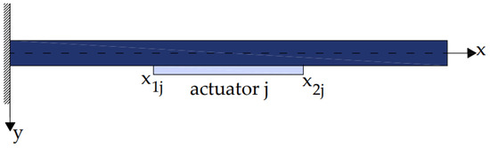
Figure 2.
Piezoelectric section (j) integrated into the beam.
Where the piezoelectric patch Pzt is placed on the beam, as indicated by the transfer function H. The torsion Mpx is given by the following:
where [18,19]
The mechanical tension epe(t) of the (piezoelectric) patch is ascertained via
Accordingly, the formulation (3) may be expressed as a bending moment,
where
Using Equation (3) and partial production in Equation (2) yields the electric force as follows:
where
Equations (1) and (8) are used to obtain the following equation, which describes the (smart) beam reaction to the vertical dynamical disturbance and the electrical dynamical force brought on by the piezoelectric patch:
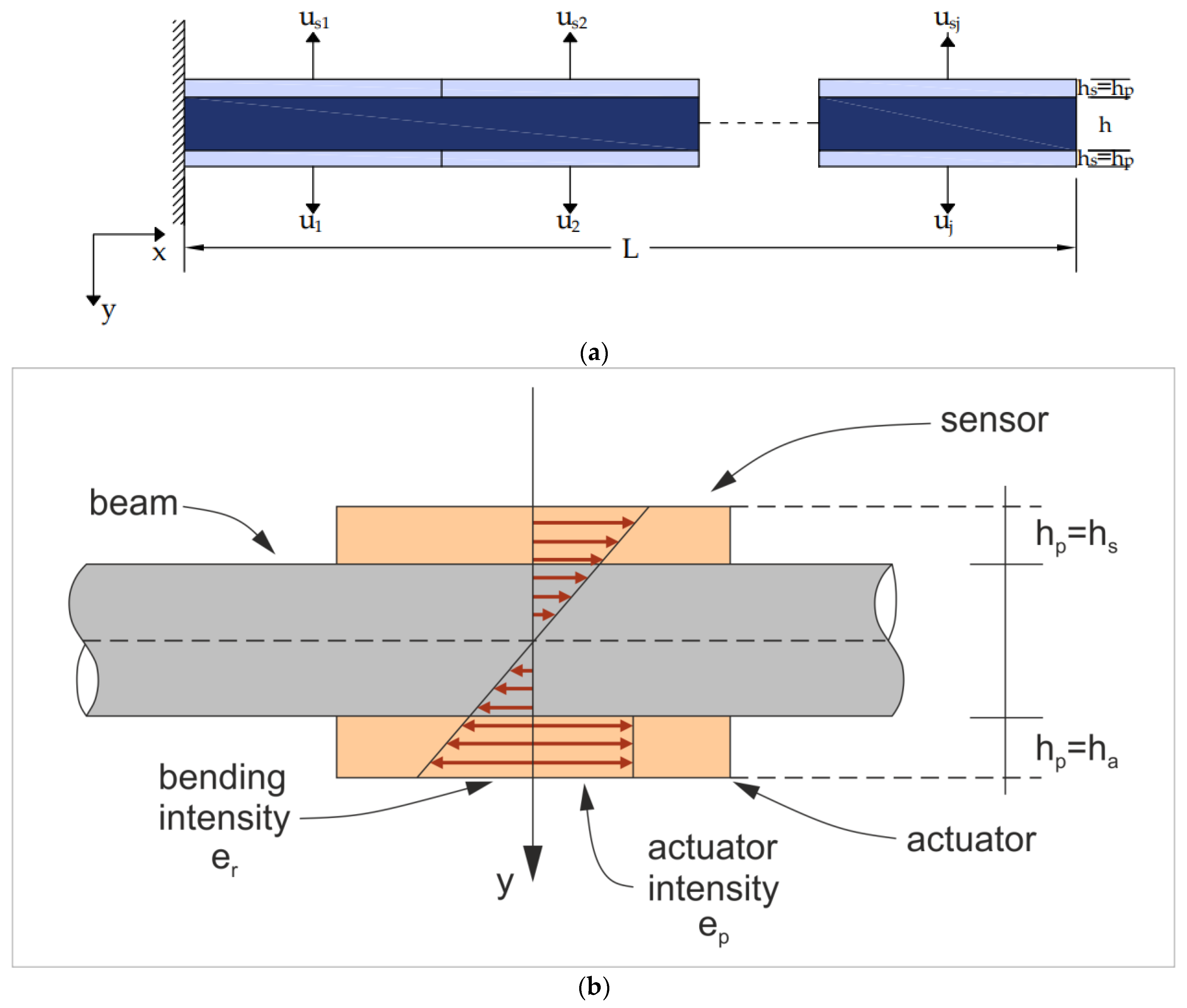
For j identical piezoelectrics (see Figure 3), Formula (9) is altered as follows:
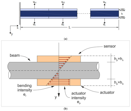
Figure 3.
(a) Smart beam supplied with integrated piezoelectric sensors and actuators. (b) The stress on the smart beam.
2.2. Modeling with FEM Analysis
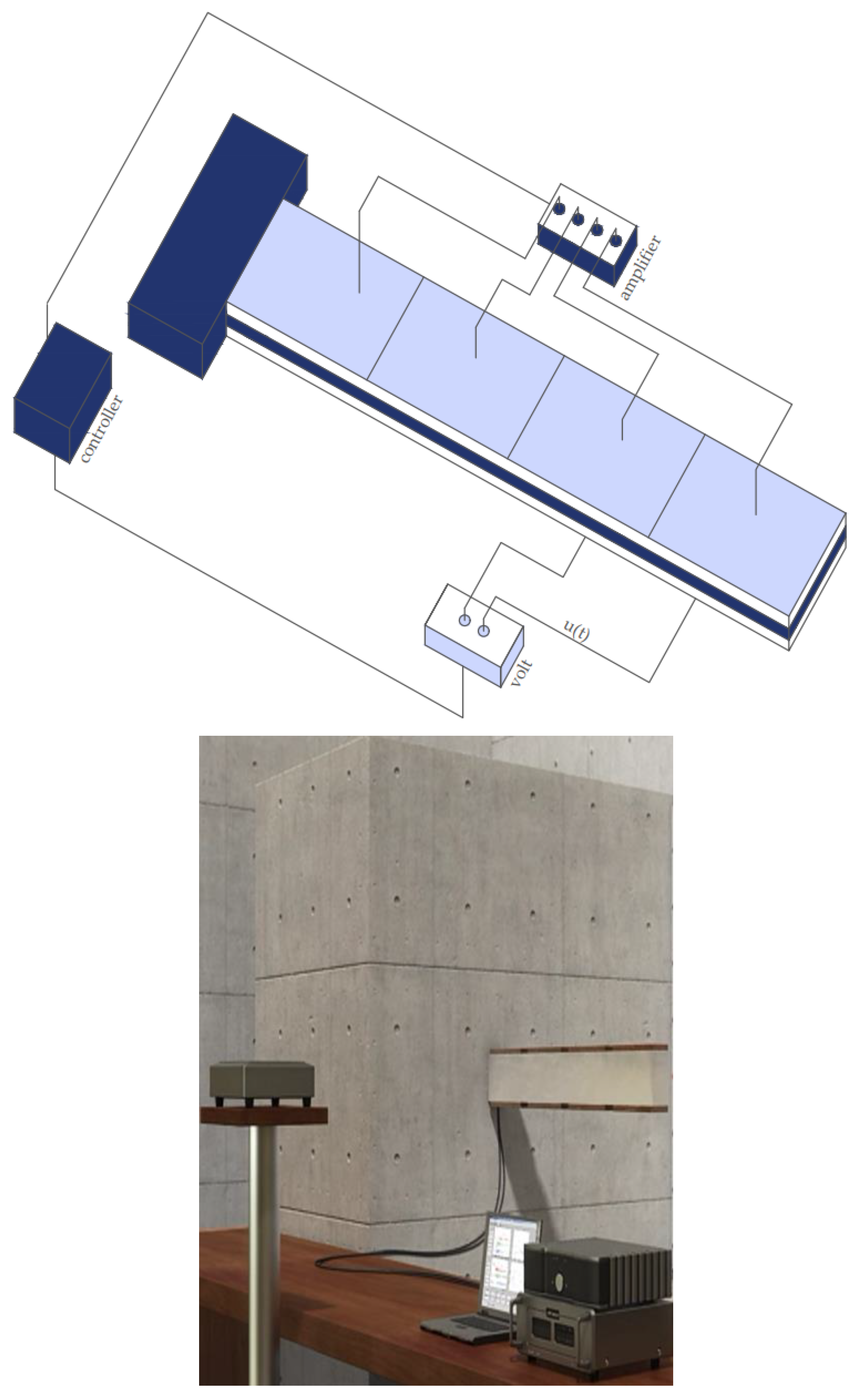
This study focused on minimizing oscillations by utilizing piezoelectric materials combined with sophisticated control techniques. In particular, the strategic positioning of the piezoelectric actuators was analyzed. As illustrated in Figure 4, the actuators were distributed along the beam, occupying spots marked as 1, 2, 3, and 4. It should be mentioned here that the dynamic characteristics of the system are detailed in references [18,19,20,21,22,23].
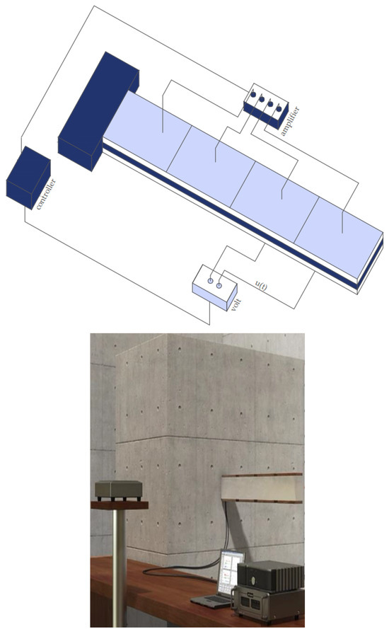
Figure 4.
Simulation with FEM analysis.
In this context, globally, fm(t) denotes the mechanical vector of the external loading, D is the viscous damping matrix, M denotes the matrix for the mass, K is the stiffness matrix, and fe(t) represents the control force vector arising from the effects of electromechanical coupling. The rotation wi and transverse deflections ψi constitute the independent factor q(t).
where n is the number of finite elements used in the investigation [5,12,28,29]. As is customary, we converted this to a state-space control representation [13,14,15,16,17].
fe(t) is defined as the piezoelectric force. This force is applied to a unit mounted on an appropriate actuator and is denoted by (2n × n).
where u denotes actuator voltage. The disturbance vector is denoted as d(t) = fm(t). Then,
By employing the output function (only displacements are assessed), this can be made better.
where
y(t) = [x1(t) x3(t) … xn − 1(t)]T= C x(t)
C= [ 1 0 0… 0; −1 0 1 0… 0; 0 0 −1 0 1… 0; 0 0 0 0 −1 0 1… 0]
The capacity of the piezoelectric effect to transform mechanical stress into strain and vice versa forms the foundation for the oscillation suppression achieved in this study.
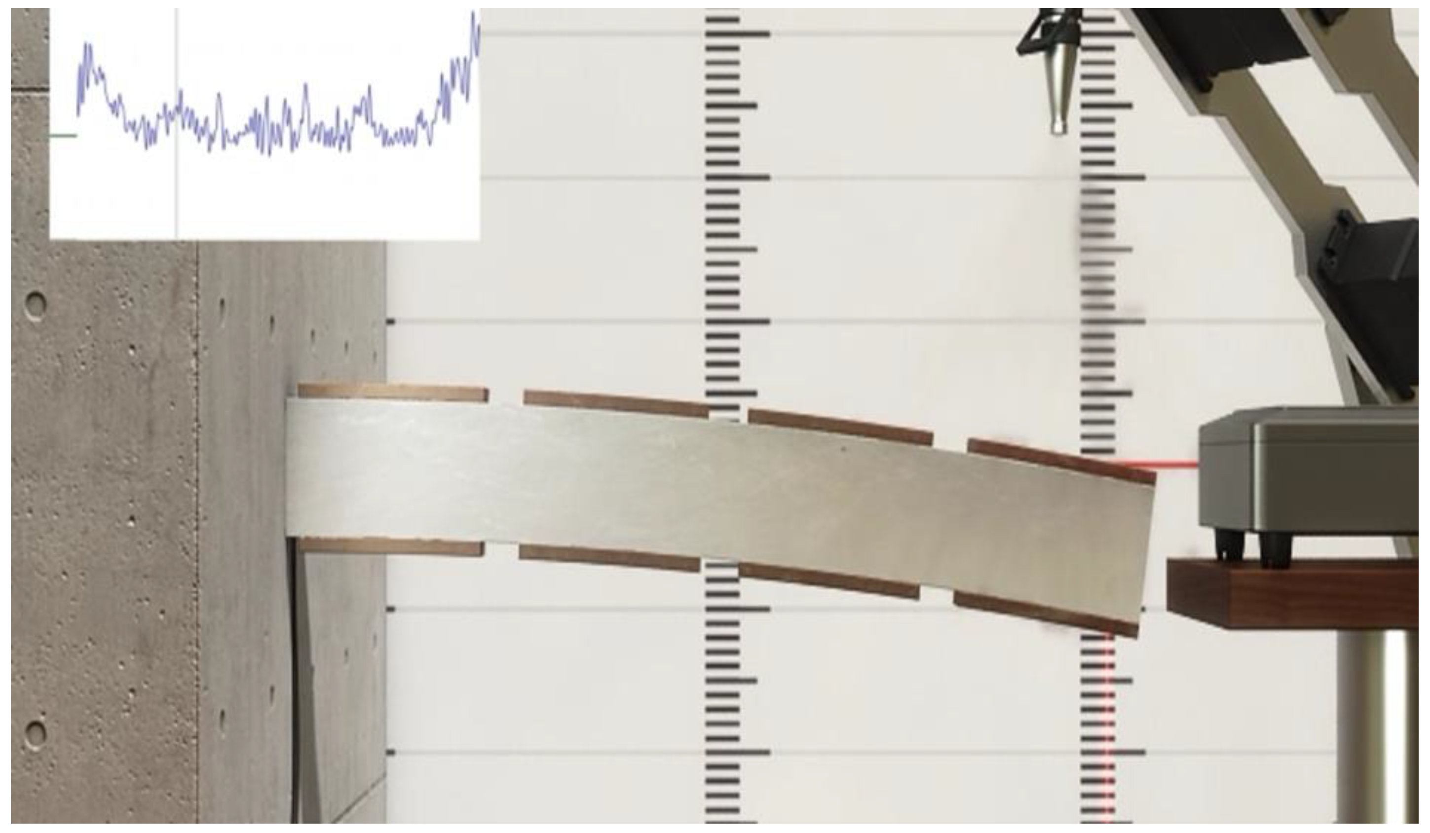
As shown in Figure 5, we utilized co-localized actuator pairs with piezoceramic (PZT G-1195) integrated into laminated composite (glass/epoxy, graphite/epoxy) and metallic (aluminum) beams. Table 1 provides a complete breakdown of smart beam parameters.
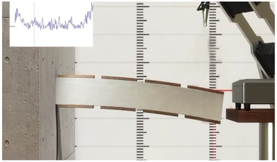
Figure 5.
The vibration of the intelligent structure without the piezoelectric force fe(t) and without the control theory.

Table 1.
Settings of the smart beam.
In our simulation
3. Results
3.1. Controller Synthesis with (D, G-K) Iteration
The D−K iteration method is a widely used technique in robust control theory designed to create controllers that stabilize a system and achieve the desired performance criteria, particularly when dealing with systems that have uncertainties. This method aims to minimize the μ value, a measure of robustness, through an iterative process.
The method starts with an initial controller K(s) = (AK, BK, CK, DK), represented in state-space form as matrices defining the controller dynamics. The first step involves evaluating the performance of the closed-loop system with this initial controller by computing the μ value, which quantifies the robustness of the system to uncertainties [5,12,27,28,32,33,34,35].
Next, this method computes the frequency-dependent weighting function, D(ω). These scaling functions, which minimize the μ value at each frequency ω, are then used to weigh the transfer functions of the system. The subsequent step involves updating the controller K(s) using the D(ω) functions. This step typically requires solving an H∞ optimization problem to find a new controller that minimizes the weighted μ value.
The iteration process is repeated until the controller K(s) converges, meaning that the μ value no longer changes significantly with further iterations. This iterative process continues until a robust controller is obtained, ensuring that the system maintains its performance in the presence of uncertainties [5,12,27,28,32,33,34,35].
The D−Κ iteration method is beneficial owing to its robustness and flexibility. It can handle both structured and unstructured uncertainties, making it suitable for various engineering fields, including aerospace, automotive, and manufacturing, where system robustness is critical. In terms of mathematical formulation, the process begins by defining the generalized plant P and the initial controller K(s) [32,36,37]. For the closed-loop system, the structured singular value μ-controller was computed for the transfer function matrix. The D(ω) function was then determined to minimize the μ value for each frequency ω. The H∞ optimization problem was solved to determine the new controller K(s), and the convergence was checked. If the μ value did not change significantly, the iteration stopped; otherwise, the process was repeated. In summary, the D−Κ iteration method provides a systematic approach for designing robust controllers for complex systems with uncertainties, ensuring stability and desired performance levels [5,12,27,28,32,33,34,35].
In our work, the methods discussed provide several approaches for comparing and evaluating controller performance while addressing analytical challenges. However, a controller can be designed to achieve an approximate specific performance level by using a structured single μ value. This approach, called (D, G-K) iteration [17,20,21,35], transforms the problem of converting a μ-optimal controller K(s) into a more manageable problem.
In this context, μ- represents a performance measure that must be minimized across all frequencies, ω. The objective is to ensure that μ(F(jω), K(jω)) ≤ β for every ω, where β is a predefined threshold.
The (D, G-K) iteration method involves identifying two transfer function matrices, that is, the D(ω) matrix and G(ω) matrix, which belong to the H∞ space, meaning that they are stable and have bounded infinity norms. By finding appropriate D(ω) and G(ω) matrices, the original problem of designing a μ-optimal controller is converted into the task of solving these matrices, simplifying the design process and making it easier to achieve the desired performance level.
Unfortunately, there is no assurance that the local maxima can be found using this method. However, for complex perturbation management, the method mentioned above (D-K iterations) is utilized. This approach, which is also performed in MATLAB (v. 7.3, Mathworks, Natick, MA, USA), combines μ-analysis and H∞ synthesis and typically yields satisfactory results. The procedure begins with a scaled singular-value-based upper constraint on μ.
The aim is to identify the controller that minimizes the upper bound’s peak over the frequency:
This is accomplished by interchanging between minimizing with respect to either the K factor or the D factor (while keeping the remaining parameters fixed) [30,35].
The objective of this task is to utilize the state-space formulas K(s) = (AK, BK, CK, DK) to identify a suitable controller. The infinity norm represents the maximum two-norm perturbation that can be tolerated while maintaining the stability of the closed-loop system. The term “spectral abscissa” used below refers to the highest real component of the poles or eigenvalues of a closed-loop system.
To define P in state space, the natural partitioning is formed:
(In cases where the packed form has been employed), the comparable form of K(s) is
Equation (4) defines the functions
and
We broke the feedback loop and used pertinent equations to determine the matrices involved. The outputs, states, inputs, and input/output are connected to the controller to obtain the structure in the state-space form:
Let
Swapping the internal signals d, n, and e και x, where x is the state vector, d is the disturbance in our work as the external mechanical force, u is the control vector, w is the input of the disturbances (d) and the noise (n), and z is the output the control vector(u) and the errors (e).
Therefore, the matrices are
The state vector in this system was 16 + 4 + 4 + 4 + 8 = 36. This also defines the size of the controller model K(s). This number was lowered in the appropriate order if the weight measurements remained constant [22,23,24].
Finding a single controller K(s) = (AK, BK, CK, DK) with state-space formulas AK ∈ RnK×nK and BK, CK, and DK having dimensions consistent with AK, as well as the generalized plant matrices, is the most challenging aspect of the task. Because the controller order K is set, the designer can specify it [25,26,36,37]. If the w and z performance channels are not stated and the Hinfinity rule is not established, then the highest two-norm perturbation that may be accepted without compromising the stability of the perturbed system is the complex stability radius for a steady closed-loop system [32,36,37]. The closed-loop system’s largest real component of its poles (eigenvalues) is its spectral abscissa.
When the w and z performance channels are not defined and the H∞ norm is not given, the complex stability radius of a stable closed-loop system is defined as the largest two-norm perturbation that the system can withstand and maintain [32,36,37]. Furthermore, the spectral abscissa of a closed-loop system is the largest real component of its poles or eigenvalues, which is a crucial aspect in determining the stability of the system.
3.2. Mechanical External Disturbance (d = fm(t))
External loading was applied to the edges of the smart beam. The first static load was a force of magnitude 10 KN. This force was applied at the edge of the smart construction. A sinusoidal charge was introduced at the edge of the carrier. The third external loading was the wind loading at the edge of the carrier (Figure 5 and Figure 6).
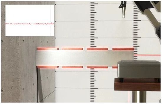
Figure 6.
In the vibration suppuration of the intelligent structure with the piezoelectric force fe(t), the displacement is almost zero using the control theory, even with a dynamic strong force.
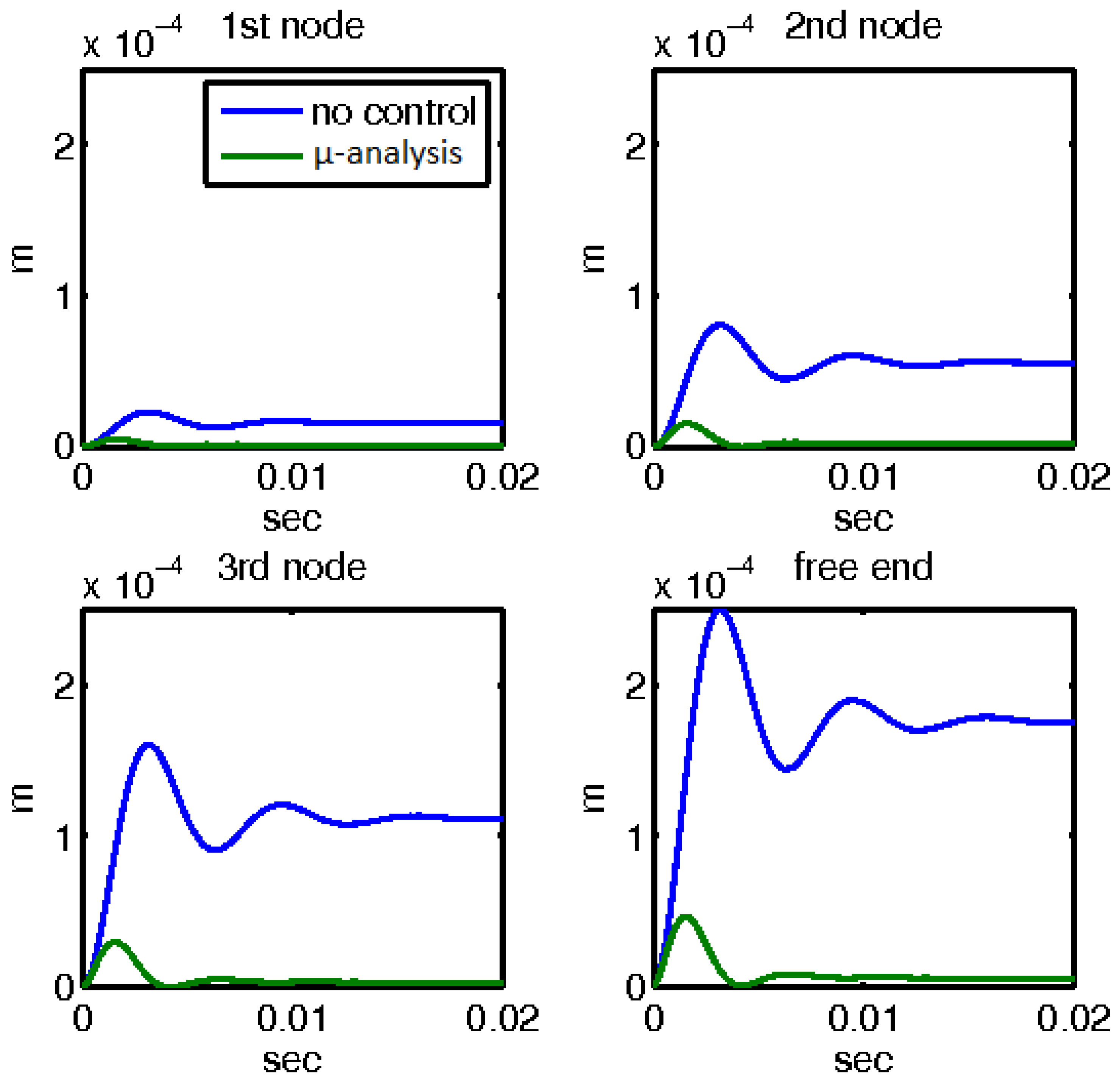
For the first mechanical external disturbance of 10N applied at the free end of the beam, the responses with and without the control mechanisms are shown in Figure 7 and Figure 8. Figure 7 presents the displacement outcomes for four nodes within the smart structure, comparing two distinct scenarios: one utilizing μ-analysis control, and the other without any control. The blue line in the graph denotes the open-loop results, which represent the behavior of the system without any control intervention. In contrast, the results incorporating the control theory, specifically the μ-analysis, are displayed separately. Remarkably, when the control theory was applied, the displacements were reduced to nearly zero, indicating the effective mitigation of the disturbance.
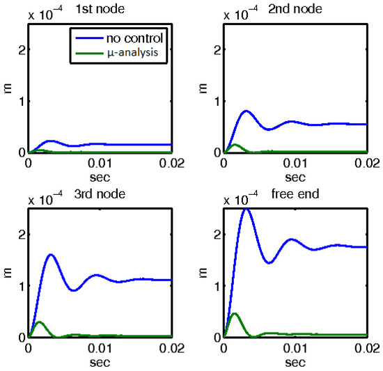
Figure 7.
Displacements with and without control with the μ-controller for the four nodes of the smart beam.
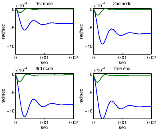
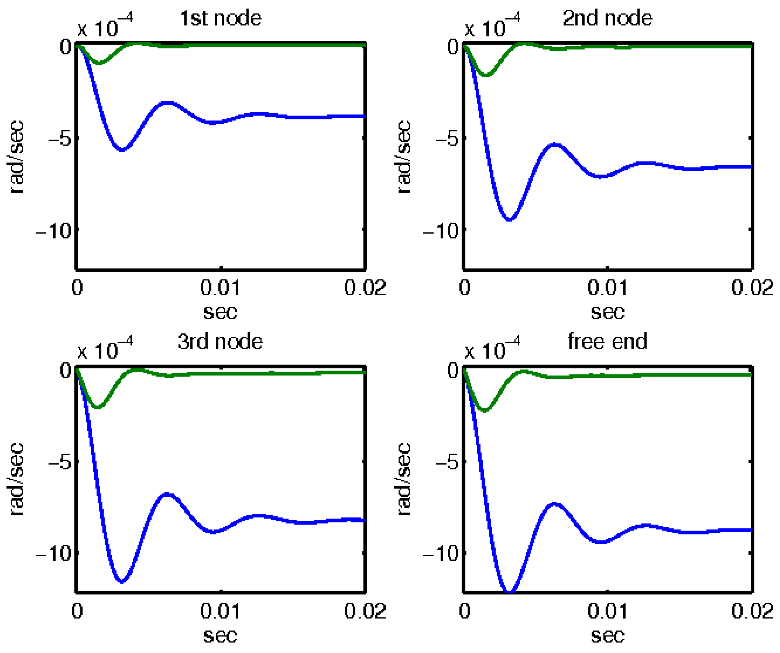
Figure 8.
Rotations with and without control with the μ-controller for the four actuators of the smart beam.
Similarly, Figure 8 depicts the rotational responses for the same four nodes of the smart structure under the influence of a 10N disturbance. This figure again compares the behavior of the system with and without the application of μ-analysis control. The blue line represents the open-loop results, indicating rotations without any control measures. The results obtained through the application of μ-analysis control theory are also illustrated. Notably, the rotations are minimized to almost zero when control theory is applied, demonstrating the significant impact of the control mechanism on stabilizing the structure and counteracting external disturbances.
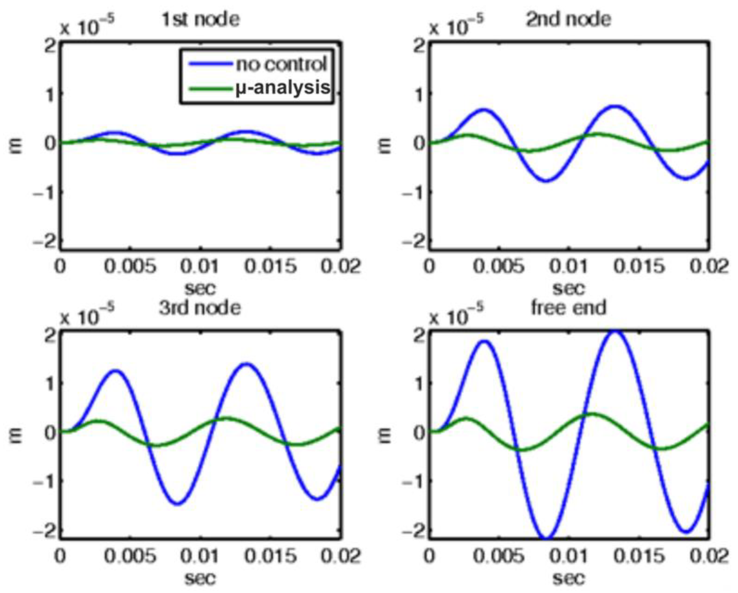
For the second mechanical external disturbance, a sinusoidal load of amplitude 10 N was applied at the free end of the beam, and the responses with and without the control mechanisms are comprehensively illustrated in Figure 9 and Figure 10. Figure 9 depicts the displacement outcomes for four nodes within the smart structure, comparing two distinct scenarios: one scenario employs μ-analysis control, whereas the other operates without any form of control. In this figure, the blue line represents the open-loop results, which indicate system behavior in the absence of any control intervention. Conversely, the results incorporating control theory, specifically using μ-analysis, are displayed separately. Notably, when the control theory was applied, the displacements were significantly reduced to nearly zero, indicating effective mitigation of the disturbance by the control system.
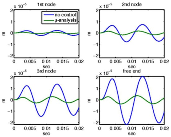
Figure 9.
For sinusoidal force at the end of the smart structure, displacements with and without control with the μ-controller for the four actuators of the smart beam.
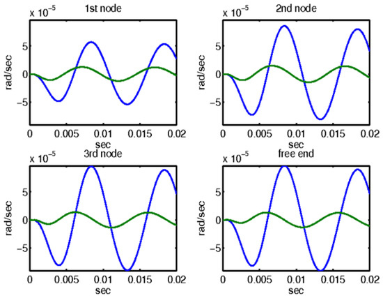
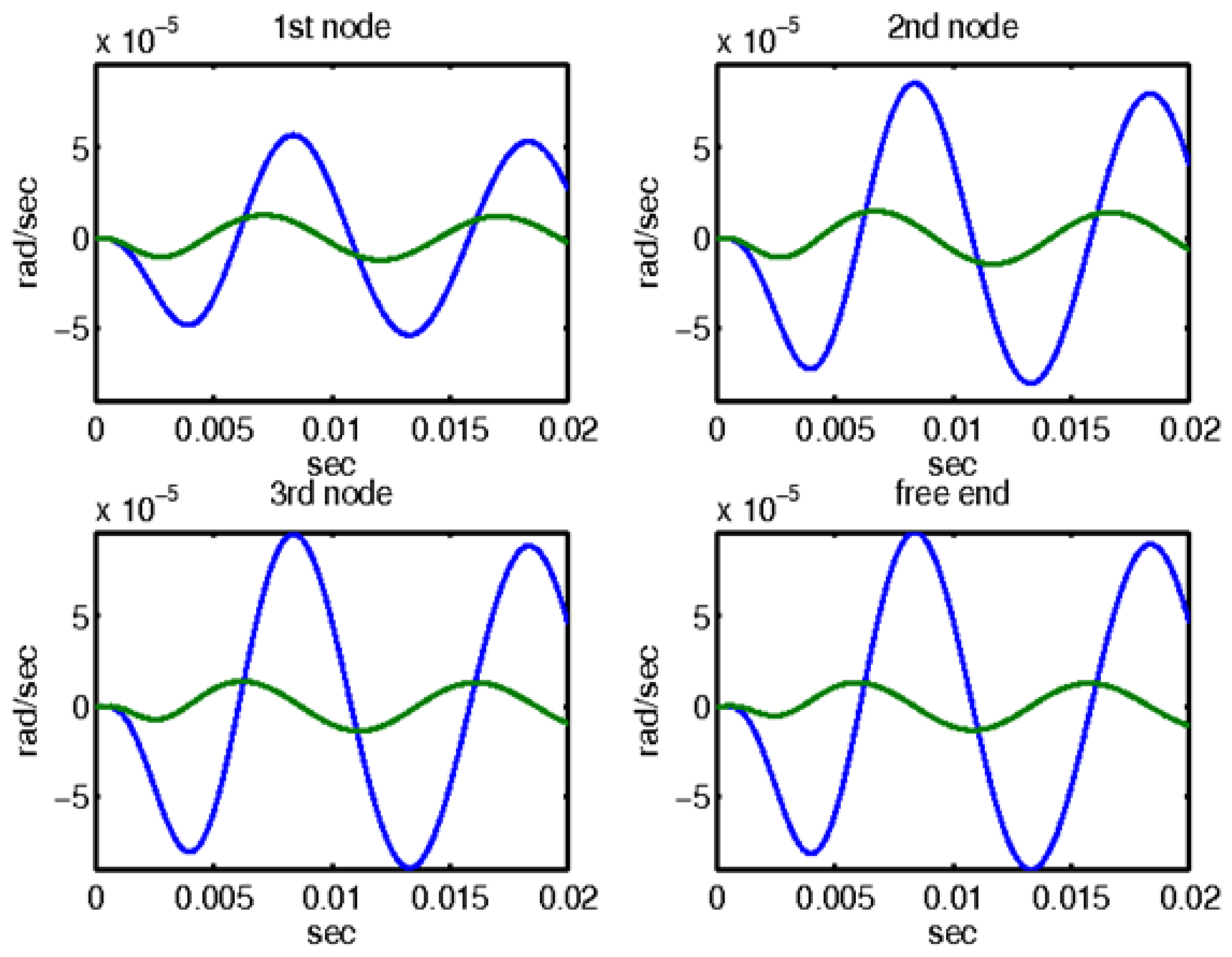
Figure 10.
For sinusoidal force at the end of the smart structure, rotations with and without control with thee μ-controller for the four actuators of the smart beam.
Similarly, Figure 10 depicts the rotational responses for the same four nodes of the smart structure when subjected to a sinusoidal disturbance. This figure provides a comparative analysis of the system behavior with and without the application of μ-analysis control. The blue line in the graph denotes the open-loop results, highlighting the rotations experienced by the structure without control measures. In addition, the results obtained by applying μ-analysis control theory are illustrated. Notably, the rotations are substantially minimized to almost zero when control theory is applied. This demonstrates the significant impact and efficacy of the control mechanism in stabilizing the structure and counteracting the effects of external disturbances. The ability of the control system to nearly nullify both displacements and rotations underscores its critical role in maintaining the structural integrity of the beam under sinusoidal loading conditions.
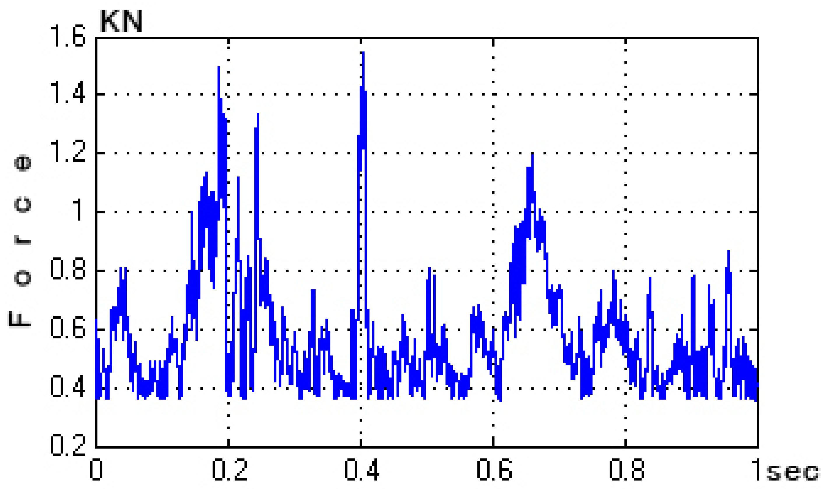
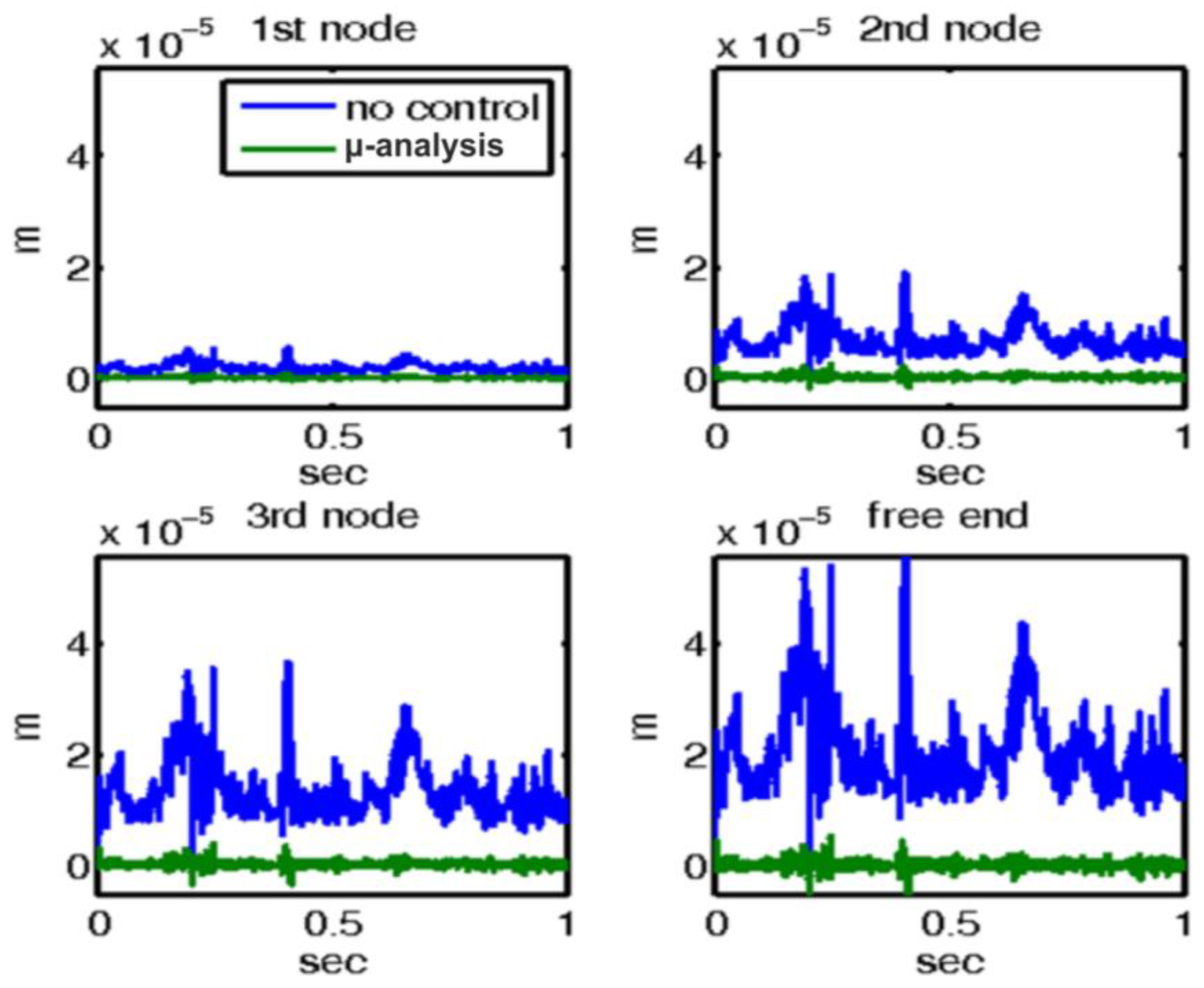
For the third mechanical external disturbance, a real wind force (depicted in Figure 11) was applied to the free end of the beam. The responses of the system with and without the control mechanisms are illustrated in Figure 12 and Figure 13, respectively. Figure 12 provides an in-depth presentation of the displacement outcomes for the four nodes within the smart structure. This comparison includes two distinct scenarios: one utilizing μ-analysis control, and the other operating without any form of control. In this figure, the blue line represents the open-loop results, which indicate system behavior in the absence of any control intervention. In contrast, the results that incorporate control theory, specifically using μ-analysis, are displayed separately. It is noteworthy that when the control theory is applied, the displacements are significantly reduced to nearly zero, indicating the effective mitigation of the disturbance by the control system. This dramatic reduction in displacement highlights the efficacy of the control mechanism in maintaining the structural stability of the beam against wind forces.

Figure 11.
Wind force.

Figure 12.
For wind force at the end of the smart structure, displacements with and without control with the μ-controller for the four actuators of the smart beam.

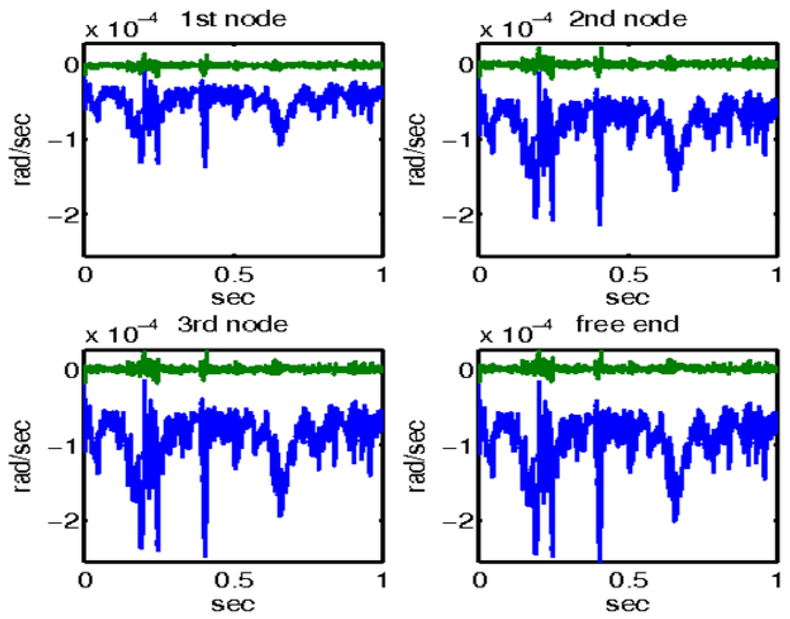
Figure 13.
For wind force at the end of the smart structure, rotations with and without control with the μ-controller for the four actuators of the smart beam.
Similarly, Figure 13 depicts the rotational responses for the same four nodes of the smart structure when subjected to a real wind force. This figure provides a comparative analysis of the system behavior with and without the application of μ-analysis control. The blue line in the graph denotes the open-loop results, highlighting the rotations experienced by the structure without control measures. In addition, the results obtained by applying the μ-analysis control theory are illustrated. Notably, the rotations are substantially minimized to almost zero when control theory is applied. This demonstrates the significant impact and efficacy of the control mechanism in stabilizing the structure and counteracting the effects of external disturbances.
The ability of the control system to nearly nullify both displacements and rotations underscores its critical role in maintaining the structural integrity of the beam under wind-loading conditions. This level of control ensured that the beam could withstand external disturbances without significant deformation or instability. Thus, the application of μ-analysis control is a highly effective strategy for enhancing the resilience and robustness of smart structures when faced with real-world environmental challenges, such as wind forces.
In the next simulation conducted in the frequency domain, the closed-loop system performance was analyzed from two different perspectives. Figure 14 shows the maximum singular value for the closed-loop system with respect to the disturbance (d) and noise (n) that influence the control (u). This figure provides insight into the effectiveness of the control system in mitigating disturbances and noise, thereby maintaining the desired stability and system performance.
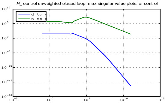
Figure 14.
Maximum singular value for the closed-loop system (noise and disturbance to regulate).
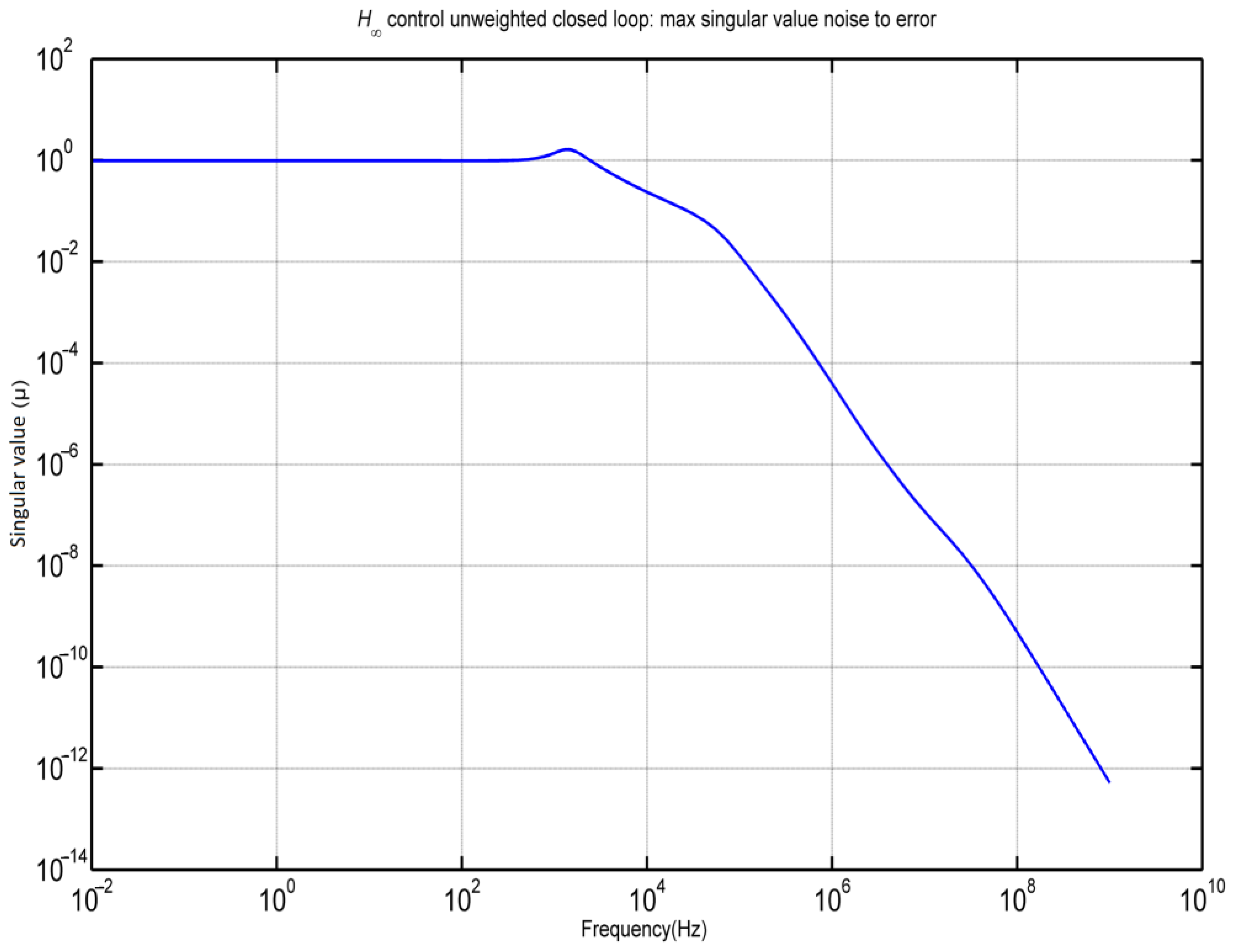
Figure 15, however, illustrates the highest singular value for the closed-loop system with respect to the noise (n) that affects the error (e). This figure highlights the capability of the control system to reduce the errors caused by noise, thereby ensuring that the system output remains accurate and reliable despite the presence of external noise.
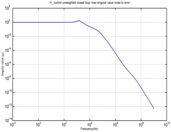
Figure 15.
Maximum singular value (noise to error) for the closed-loop system.
Together, these figures offer a comprehensive analysis of the closed-loop system’s performance in handling disturbances and noise. Figure 14 focuses on the system’s ability to manage disturbances and noise through control actions, whereas Figure 15 emphasizes the system’s proficiency in minimizing noise-induced errors. This dual perspective is crucial for understanding the overall effectiveness and robustness of control systems under various operational conditions.
4. Discussion
In this study, we introduced advancements in intelligent control to reduce structural vibrations. The field of intelligent control for dampening structural vibrations is evolving rapidly, driven by progress in materials science, AI, and actuator technology. These innovations have led to more efficient, reliable, and adaptable vibration-control systems with applications ranging from civil engineering to aerospace. The use of smart materials, particularly piezoelectric materials, has provided new avenues for vibration control [28,29,30,31]. These materials generate an electric charge in response to mechanical stress, allowing for precise control over vibrations. Improved computational models and simulations also play crucial roles in the design and testing of vibration-control systems. Finite element analysis (FEA) helps to accurately predict the behavior of structures under various loads, aiding in the design of effective vibration-control systems. In our study, we applied intelligent control theory to dampen structural vibrations in engineering structures [27,28,31,34].
This study delves into various facets of multi-objective robust control, focusing on simultaneous and strong stabilization. This study addresses the main challenges and benefits of these approaches. Simultaneous stabilization involves the creation of a single controller that can stabilize multiple plants, whereas strong stabilization requires designing a controller that not only stabilizes the plant but is also inherently stable. A significant challenge in these areas is that many existing methods and heuristics tend to produce controllers with extremely high orders, which is impractical. Ensuring that the control behavior aligns with theoretical predictions is also a critical concern [27,28,31,34].
This study underscores the benefits of robust control, particularly through infinity regulation, which aims to achieve optimal performance despite uncertainties and disturbances. The application of these methods yields several notable results, including the optimization of the infinity controller order for smart structures and the effective suppression of oscillations by utilizing intelligent entity modeling, which spans both the time-space and frequency domains, incorporating the measurement noise of the beam state to ensure robustness. The methods demonstrated the complete suppression of oscillations and effective handling of disturbance inputs using white noise as a percentage of total disturbances. The MATLAB software platform (v. 7.3, Mathworks, Natick, MA, USA) was used for programming and simulations to validate theoretical models and methods. These findings demonstrate the practical benefits of the proposed control strategy for smart structures. Future research will concentrate on investigating several approaches to further reduce structural noise and vibration, as well as implementing these control mechanisms in actual intelligent structures in experimental environments. This study emphasizes the need for strong control in intelligent systems and demonstrates how infinity regulation helps achieve both efficient control and noise reduction.
5. Conclusions
In our study, we emphasize the significant advancements in intelligent control systems aimed at reducing structural vibrations. The field of intelligent control for dampening these vibrations is rapidly progressing owing to breakthroughs in materials science, artificial intelligence, and actuator technology. These innovations have led to more efficient, reliable, and adaptable vibration-control systems with broad applications in various fields, including civil engineering and aerospace.
The introduction of smart materials, particularly piezoelectric materials, has revolutionized vibration control. These materials generate electric charges in response to mechanical stress, allowing for precise vibration management. Advancements in computational models and simulations are crucial for the design and testing of such systems. Finite element analysis (FEA) plays a pivotal role in accurately predicting the behavior of structures under different loads, which is essential for creating effective vibration-control systems.
Our research leverages the intelligent control theory to dampen structural vibrations in engineering applications. By integrating the latest innovations in smart materials and computational modeling, we aim to develop advanced vibration-control systems that enhance the stability and performance of the structures. These systems not only improve safety and durability but also contribute to the advancement of engineering practices in various high-demand sectors.
This research has various advantages, such as the optimization of the H∞ controller order investigated in smart structures, the efficient suppression of oscillations through the modeling of intelligent objects, and the acquisition of outcomes in both the frequency and time domains. Moreover, this study explores the impact of noise measurement on the beam state, achieving complete oscillation suppression and reducing the order of the controller. White noise, which was treated as a percentage of the total disturbance, was used as the disturbance input. The results were generated through extensive programming and simulations using MATLAB software (v. 7.3, Mathworks, Natick, MA, USA). Additionally, the study delves into applying measurement noise to the beam state, successfully achieving full oscillation suppression and reducing the complexity of the controller. White noise, introduced as a disturbance input, represents the percentage of total disturbances.
Looking ahead, future studies will focus on two main goals: first, applying these control mechanisms to intelligent buildings in the actual world in experimental settings, thereby validating the theoretical findings in practical scenarios, and second, exploring alternative control strategies aimed at further reducing structural noise and vibration. This will involve investigating new approaches and refining existing methods to enhance the effectiveness of noise and vibration suppression in intelligent structures.
Author Contributions
G.E.S.: methodology; A.M. and M.P.: software, writing–review and editing; N.V.: validation; M.P.: formal analysis; A.P.: investigation and software. All authors have read and agreed to the published version of the manuscript.
Funding
This study did not receive any external funding.
Data Availability Statement
Data presented in this study are available upon request from the corresponding author.
Acknowledgments
The authors are grateful for the support from the Hellenic Mediterranean University and the Technical University of Crete.
Conflicts of Interest
The authors declare no conflicts of interest.
References
- Benjeddou, A.; Trindade, M.A.; Ohayon, R. New Shear Actuated Smart Structure Beam Finite Element. AIAA J. 1999, 37, 378–383. [Google Scholar] [CrossRef]
- Bona, B.; Indri, M.; Tornambe, A. Flexible Piezoelectric Structures-Approximate Motion Equations and Control Algorithms. IEEE Trans. Autom. Contr. 1997, 42, 94–101. [Google Scholar] [CrossRef]
- Okko, B.; Kwakernaak, H.; Gjerrit, M. Design Methods for Control Systems. Course Notes Dutch Inst. Syst. Control 2001, 67. [Google Scholar]
- Burke, J.V.; Henrion, D.; Lewis, A.S.; Overton, M.L. Hifoo—A MATLAB Package for Fixed-Order Controller Design and H∞ Optimization. IFAC Proc. Vol. 2006, 39, 339–344. [Google Scholar] [CrossRef]
- Burke, J.V.; Henrion, D.; Lewis, A.S.; Overton, M.L. Stabilization via Nonsmooth, Nonconvex Optimization. IEEE Trans Autom. Contr. 2006, 51, 1760–1769. [Google Scholar] [CrossRef]
- Burke, J.V.; Lewis, A.S.; Overton, M.L. A Robust Gradient Sampling Algorithm for Nonsmooth, Nonconvex Optimization. SIAM J. Optim. 2005, 15, 751–779. [Google Scholar] [CrossRef]
- Burke, J.V.; Overton, M.L. Variational Analysis of Non-Lipschitz Spectral Functions. Math. Program. 2001, 90, 317–351. [Google Scholar] [CrossRef]
- Choi, S.-B.; Cheong, C.-C.; Lee, C.-H. Position Tracking Control of a Smart Flexible Structure Featuring a Piezofilm Actuator. J. Guid. Control. Dyn. 1996, 19, 1364–1369. [Google Scholar] [CrossRef]
- Culshaw, B. Smart Structures—A Concept or a Reality? Proc. Inst. Mech. Eng. Part I J. Syst. Control Eng. 1992, 206, 1–8. [Google Scholar] [CrossRef]
- Tzou, H.S.; Gabbert, U. Structronics—A New Discipline and Its Challenging Issues. Fortschr.-Berichte VDI Smart Mech. Syst. Adapt. Reihe 1997, 11, 245–250. [Google Scholar]
- Guran, A.; Tzou, H.-S.; Anderson, G.L.; Natori, M.; Gabbert, U.; Tani, J.; Breitbach, E. Structronic Systems: Smart Structures, Devices and Systems; World Scientific: Singapore, 1998; Volume 4, ISBN 978-981-02-2652-7. [Google Scholar]
- Doyle, J.; Glover, K.; Khargonekar, P.; Francis, B. State-Space Solutions to Standard H2 and H∞ Control Problems. In Proceedings of the 1988 American Control Conference, Atlanta, GA, USA, 15–17 June 1988; pp. 1691–1696. [Google Scholar]
- Tzou, H.S.; Anderson, G.L. Intelligent Structural Systems; Springer: Dordrecht, The Netherlands; Boston, MA, USA; London, UK, 1992; ISBN 978-94-017-1903-2. [Google Scholar]
- Gabbert, U.; Tzou, H.S. IUTAM Symposium on Smart Structures and Structronic Systems. In Proceedings of the IUTAM Symposium, Magdeburg, Germany, 26–29 September 2000; Kluwer: Dordrecht, The Netherlands; Boston, MA, USA; London, UK, 2001. [Google Scholar]
- Tzou, H.S.; Natori, M.C. Piezoelectric Materials and Continua; Braun, S.B.T.-E.V., Ed.; Elsevier: Oxford, UK, 2001; pp. 1011–1018. ISBN 978-0-12-227085-7. [Google Scholar]
- Cady, W.G. Piezoelectricity: An Introduction to the Theory and Applications of Electromechanical Phenomena in Crystals; Dover Publication: New York, NY, USA, 1964. [Google Scholar]
- Tzou, H.S.; Bao, Y. A Theory on Anisotropic Piezothermoelastic Shell Laminates with Sensor/Actuator Applications. J. Sound Vib. 1995, 184, 453–473. [Google Scholar] [CrossRef]
- Vidakis, N.; Petousis, M.; Mountakis, N.; Papadakis, V.; Moutsopoulou, A. Mechanical Strength Predictability of Full Factorial, Taguchi, and Box Behnken Designs: Optimization of Thermal Settings and Cellulose Nanofibers Content in PA12 for MEX AM. J. Mech. Behav. Biomed. Mater. 2023, 142, 105846. [Google Scholar] [CrossRef]
- Petousis, M.; Vidakis, N.; Mountakis, N.; Karapidakis, E.; Moutsopoulou, A. Functionality Versus Sustainability for PLA in MEX 3D Printing: The Impact of Generic Process Control Factors on Flexural Response and Energy Efficiency. Polymers 2023, 15, 1232. [Google Scholar] [CrossRef] [PubMed]
- David, C.; Sagris, D.; Petousis, M.; Nasikas, N.K.; Moutsopoulou, A.; Sfakiotakis, E.; Mountakis, N.; Charou, C.; Vidakis, N. Operational Performance and Energy Efficiency of MEX 3D Printing with Polyamide 6 (PA6): Multi-Objective Optimization of Seven Control Settings Supported by L27 Robust Design. Appl. Sci. 2023, 13, 8819. [Google Scholar] [CrossRef]
- Moutsopoulou, A.; Stavroulakis, G.E.; Petousis, M.; Vidakis, N.; Pouliezos, A. Smart Structures Innovations Using Robust Control Methods. Appl. Mech. 2023, 4, 856–869. [Google Scholar] [CrossRef]
- Cen, S.; Soh, A.-K.; Long, Y.-Q.; Yao, Z.-H. A New 4-Node Quadrilateral FE Model with Variable Electrical Degrees of Freedom for the Analysis of Piezoelectric Laminated Composite Plates. Compos. Struct. 2002, 58, 583–599. [Google Scholar] [CrossRef]
- Yang, S.M.; Lee, Y.J. Optimization of Noncollocated Sensor/Actuator Location and Feedback Gain in Control Systems. Smart Mater. Struct. 1993, 2, 96. [Google Scholar] [CrossRef]
- Kumar, K.R.; Narayanan, S. Active Vibration Control of Beams with Optimal Placement of Piezoelectric Sensor/Actuator Pairs. Smart Mater. Struct. 2008, 17, 55008. [Google Scholar] [CrossRef]
- Hanagud, S.; Obal, M.W.; Calise, A.J. Optimal Vibration Control by the Use of Piezoceramic Sensors and Actuators. J. Guid. Control. Dyn. 1992, 15, 1199–1206. [Google Scholar] [CrossRef]
- Song, G.; Sethi, V.; Li, H.-N. Vibration Control of Civil Structures Using Piezoceramic Smart Materials: A Review. Eng. Struct. 2006, 28, 1513–1524. [Google Scholar] [CrossRef]
- Kimura, H. Robust Stabilizability for a Class of Transfer Functions. IEEE Trans. Autom. Contr. 1984, 29, 788–793. [Google Scholar] [CrossRef]
- Francis, B.A. A Course in H∞ Control Theory; Springer: Berlin/Heidelberg, Germany, 1987; ISBN 978-3-540-17069-3. [Google Scholar]
- Kwakernaak, H. Robust Control and H∞-Optimization—Tutorial Paper. Automatica 1993, 29, 255–273. [Google Scholar] [CrossRef]
- Chandrashekhara, K.; Varadarajan, S. Adaptive Shape Control of Composite Beams with Piezoelectric Actuators. J. Intell. Mater. Syst. Struct. 1997, 8, 112–124. [Google Scholar] [CrossRef]
- Blondel, V.D.; Tsitsiklis, J.N. A Survey of Computational Complexity Results in Systems and Control. Automatica 2000, 36, 1249–1274. [Google Scholar] [CrossRef]
- Moutsopoulou, A.; Stavroulakis, G.E.; Pouliezos, A.; Petousis, M.; Vidakis, N. Robust Control and Active Vibration Suppression in Dynamics of Smart Systems. Inventions 2023, 8, 47. [Google Scholar] [CrossRef]
- Zhang, N.; Kirpitchenko, I. Modelling Dynamics of a Continuous Structure with a Piezoelectric Sensoractuator for Passive Structural Control. J. Sound Vib. 2002, 249, 251–261. [Google Scholar] [CrossRef]
- Zhang, X.; Shao, C.; Li, S.; Xu, D.; Erdman, A.G. Robust H∞ Vibration Control for Flexible Linkage Mechanism Systems With Piezoelectric Sensors And Actuators. J. Sound Vib. 2001, 243, 145–155. [Google Scholar] [CrossRef]
- Packard, A.; Doyle, J.; Balas, G. Linear, Multivariable Robust Control With a μ Perspective. J. Dyn. Syst. Meas. Control. 1993, 115, 426–438. [Google Scholar] [CrossRef]
- Karatzas, I.; Lehoczky, J.P.; Shreve, S.E.; Xu, G.-L. Modeling, Control and Implementation of Smart Structures: A FEM-State Space Approach; Springer: Berlin/Heidelberg, Germany, 1990; ISBN 9783540483939. [Google Scholar]
- Miara, B.; Stavroulakis, G.E.; Valente, V. Topics on Mathematics for Smart Systems. In Proceedings of the European Conference, Rome, Italy, 26–28 October 2006; World Scientific: Singapore, 2007. [Google Scholar] [CrossRef]


Disclaimer/Publisher’s Note: The statements, opinions and data contained in all publications are solely those of the individual author(s) and contributor(s) and not of MDPI and/or the editor(s). MDPI and/or the editor(s) disclaim responsibility for any injury to people or property resulting from any ideas, methods, instructions or products referred to in the content. |
© 2024 by the authors. Licensee MDPI, Basel, Switzerland. This article is an open access article distributed under the terms and conditions of the Creative Commons Attribution (CC BY) license (https://creativecommons.org/licenses/by/4.0/).