
Comparison of Piezoelectric Stack-Based Passive and Active Vibration Suppression Systems for Satellite Solar Panels


Abstract
1. Introduction
2. Numerical Model
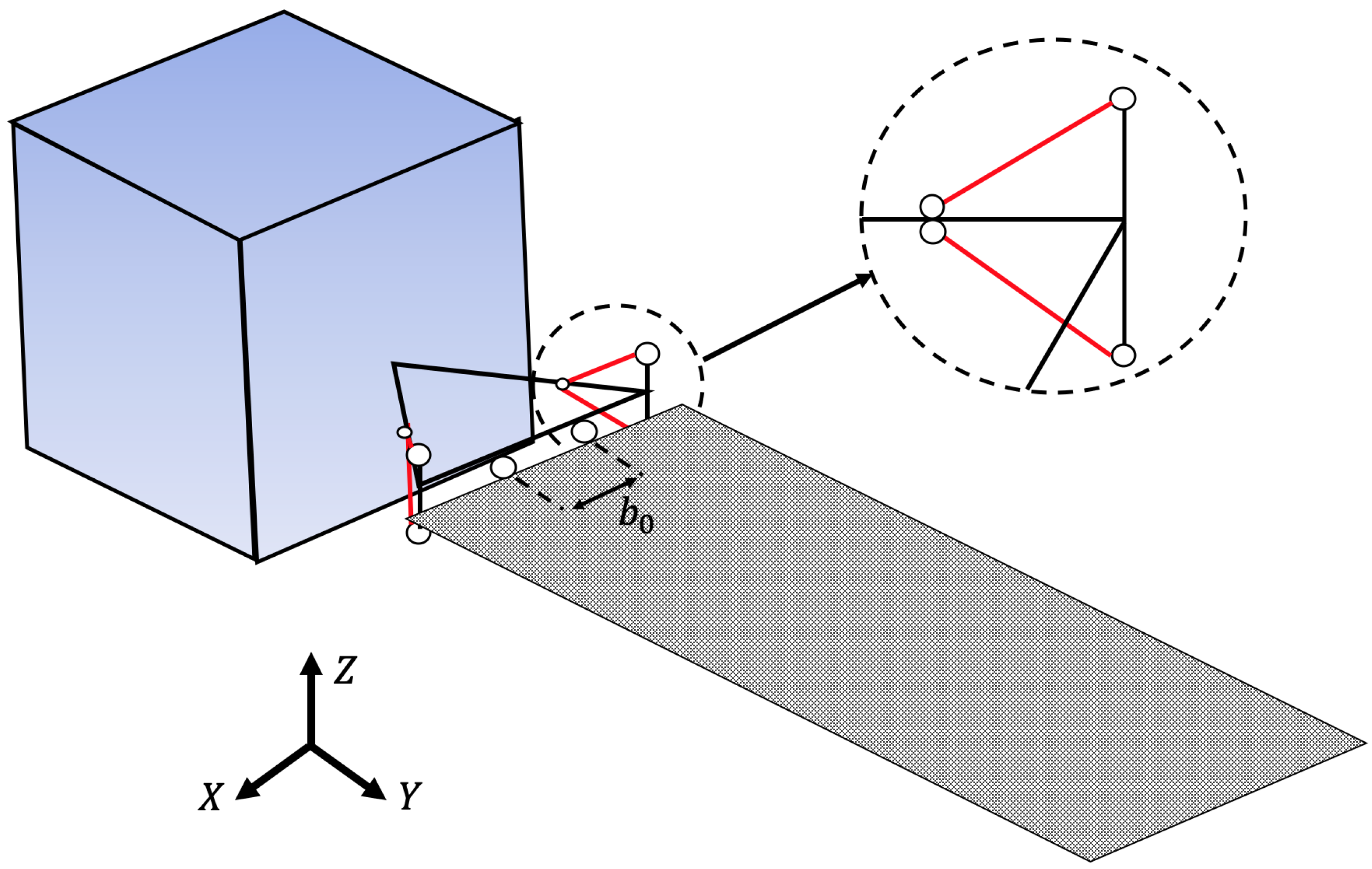
2.1. Satellite Structure
2.2. Piezoelectric Stacks Model
2.3. FEM Model
3. Control Systems
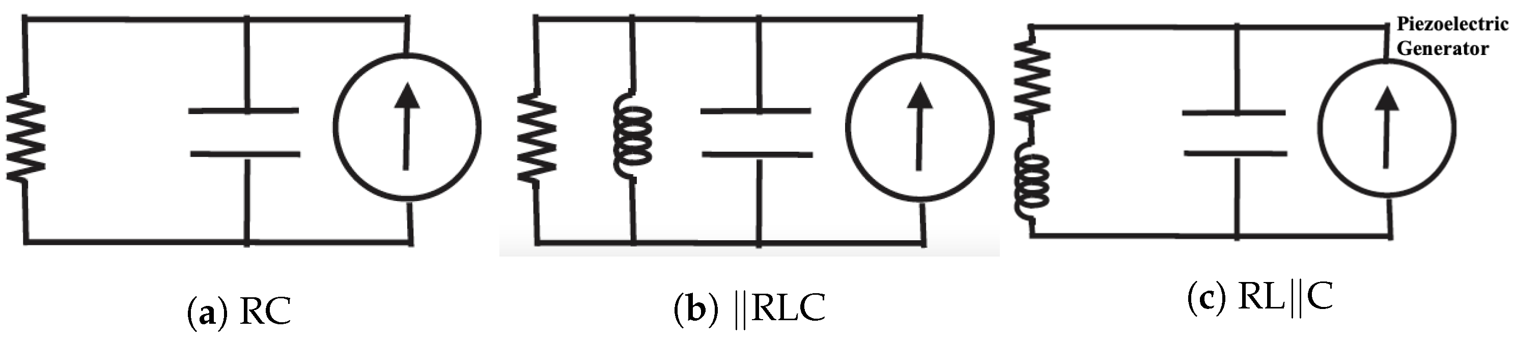
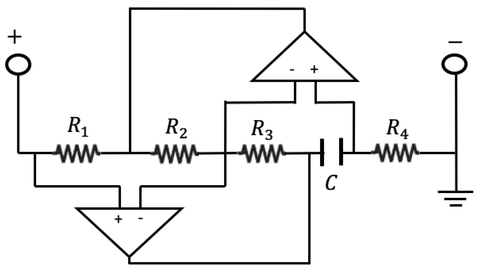
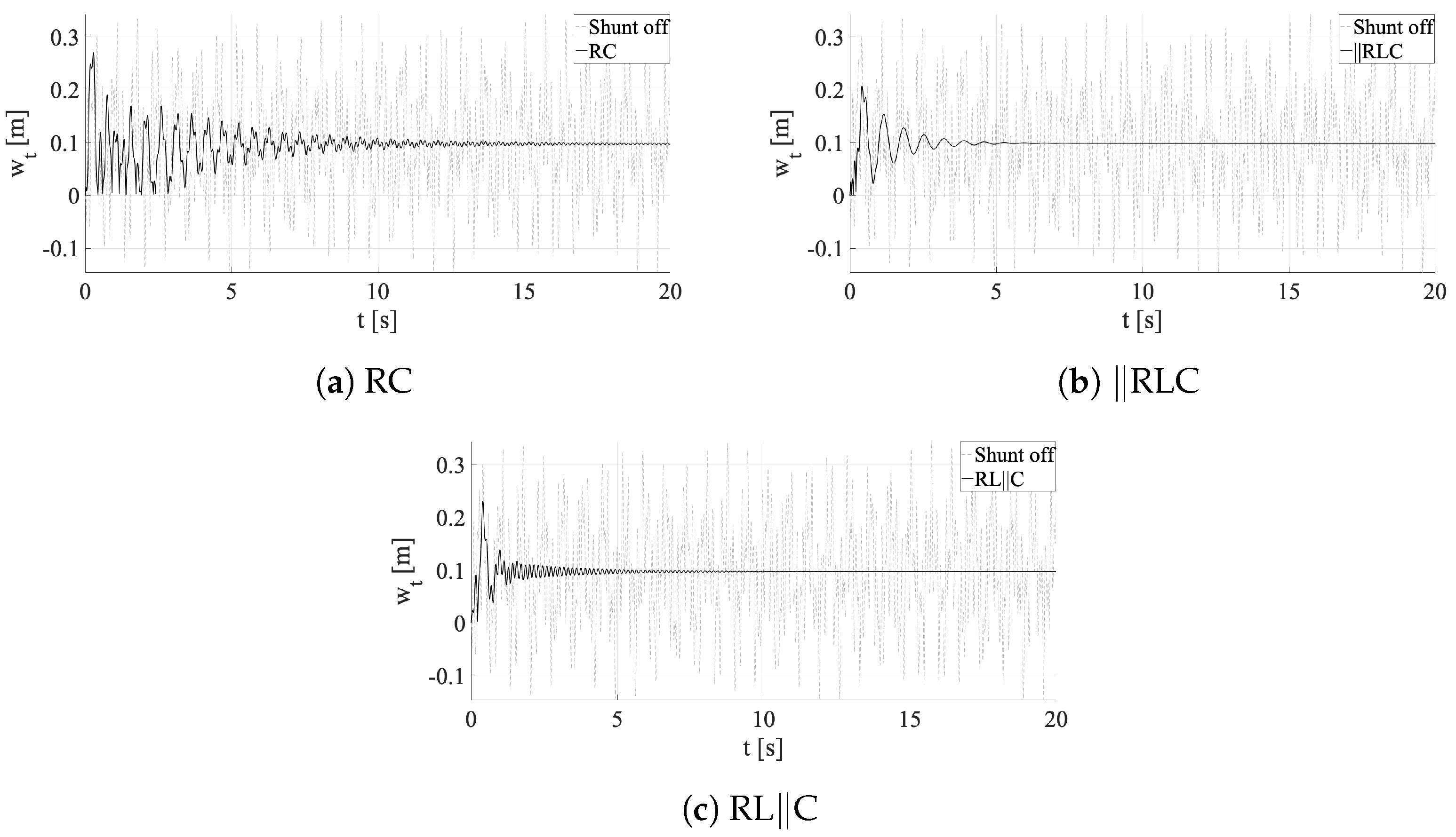
3.1. Shunt Circuits
- RC: a dissipative only circuit with a resistance R in parallel to the piezo capacity C;
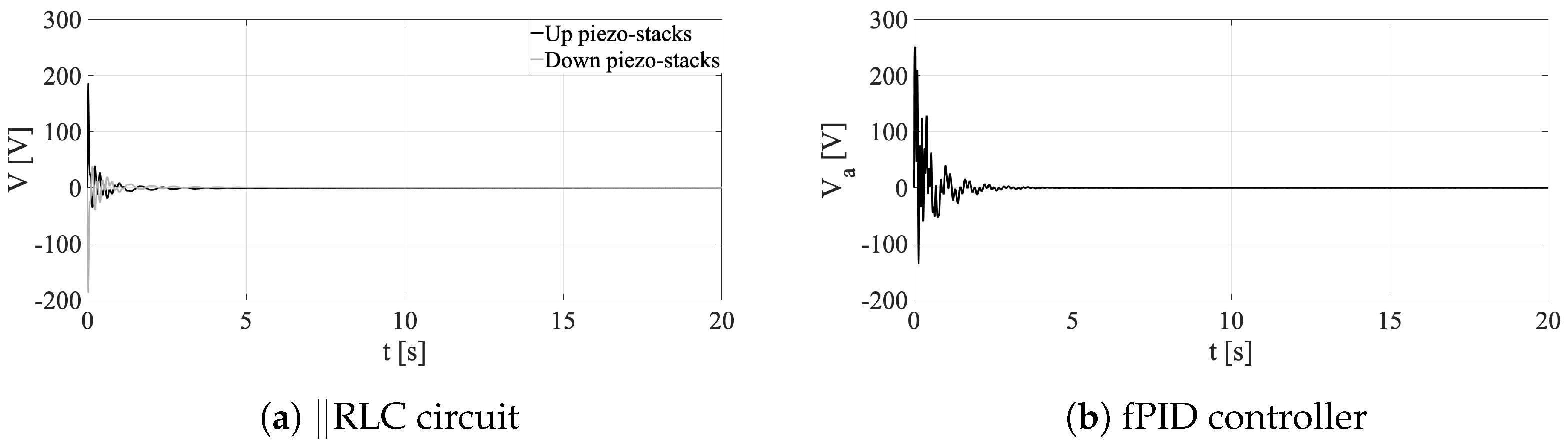
- ‖RLC: a resonant circuit with resistance, impedance L, and capacity C in parallel;
- RL‖C: a resonant circuit with resistance and impedance in series both in parallel to the capacity.
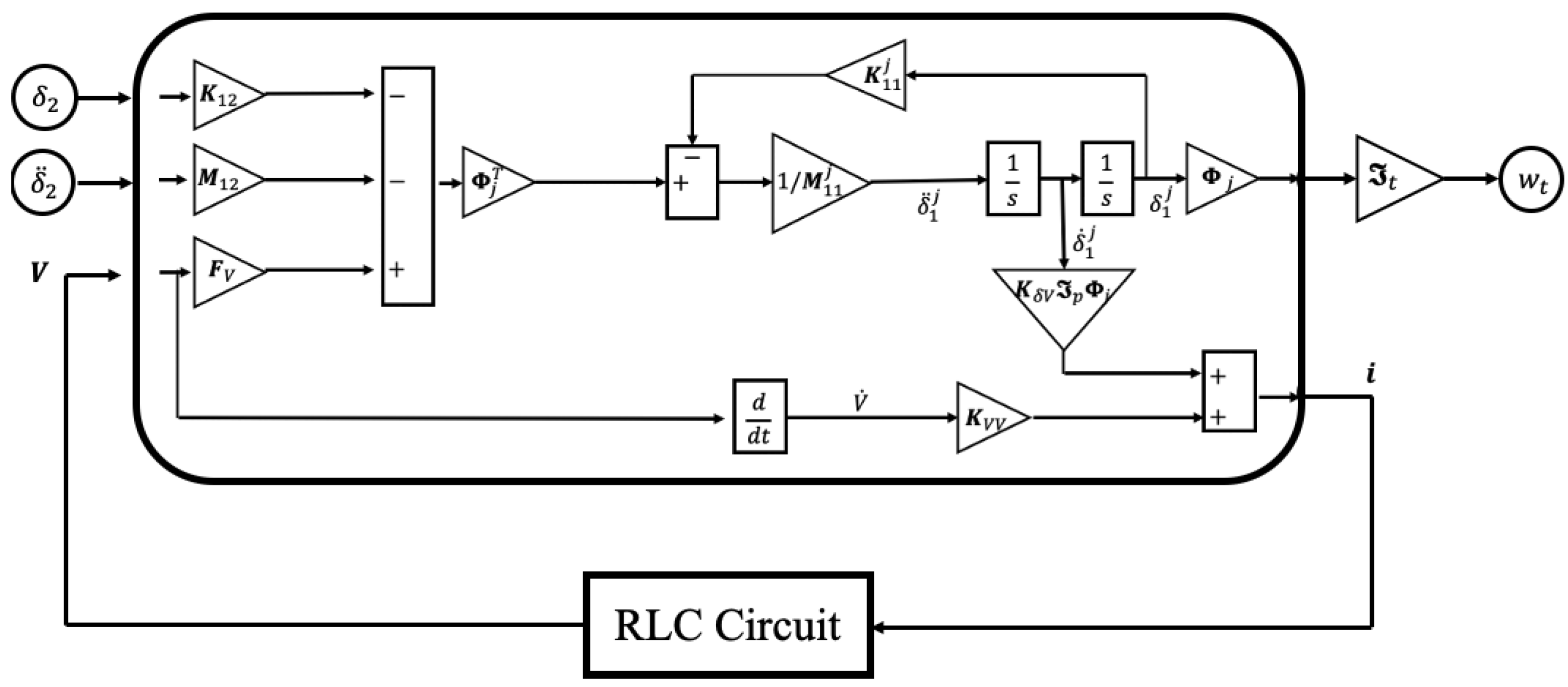
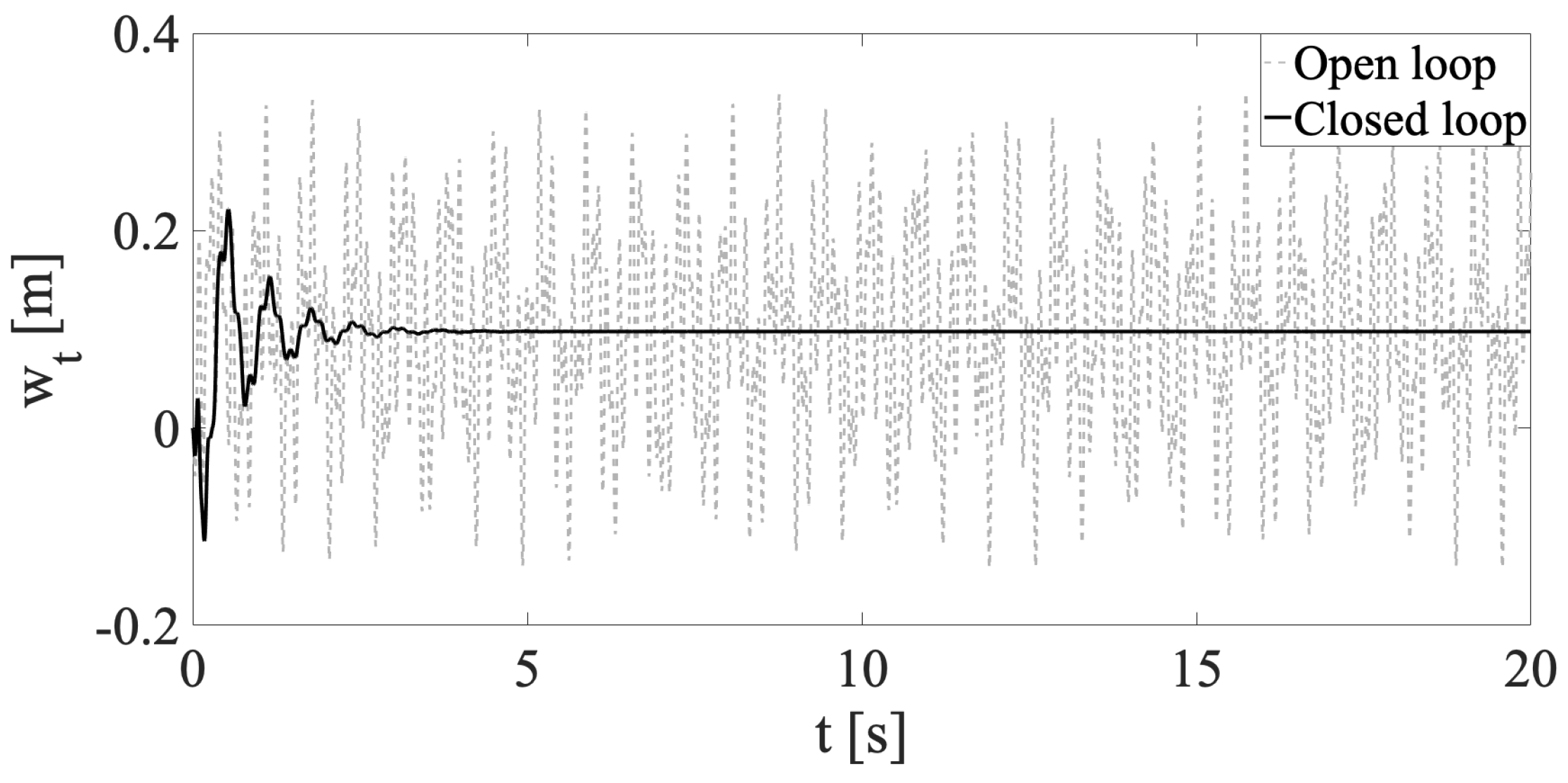
3.2. Active Control
4. Results
4.1. Modal Analysis
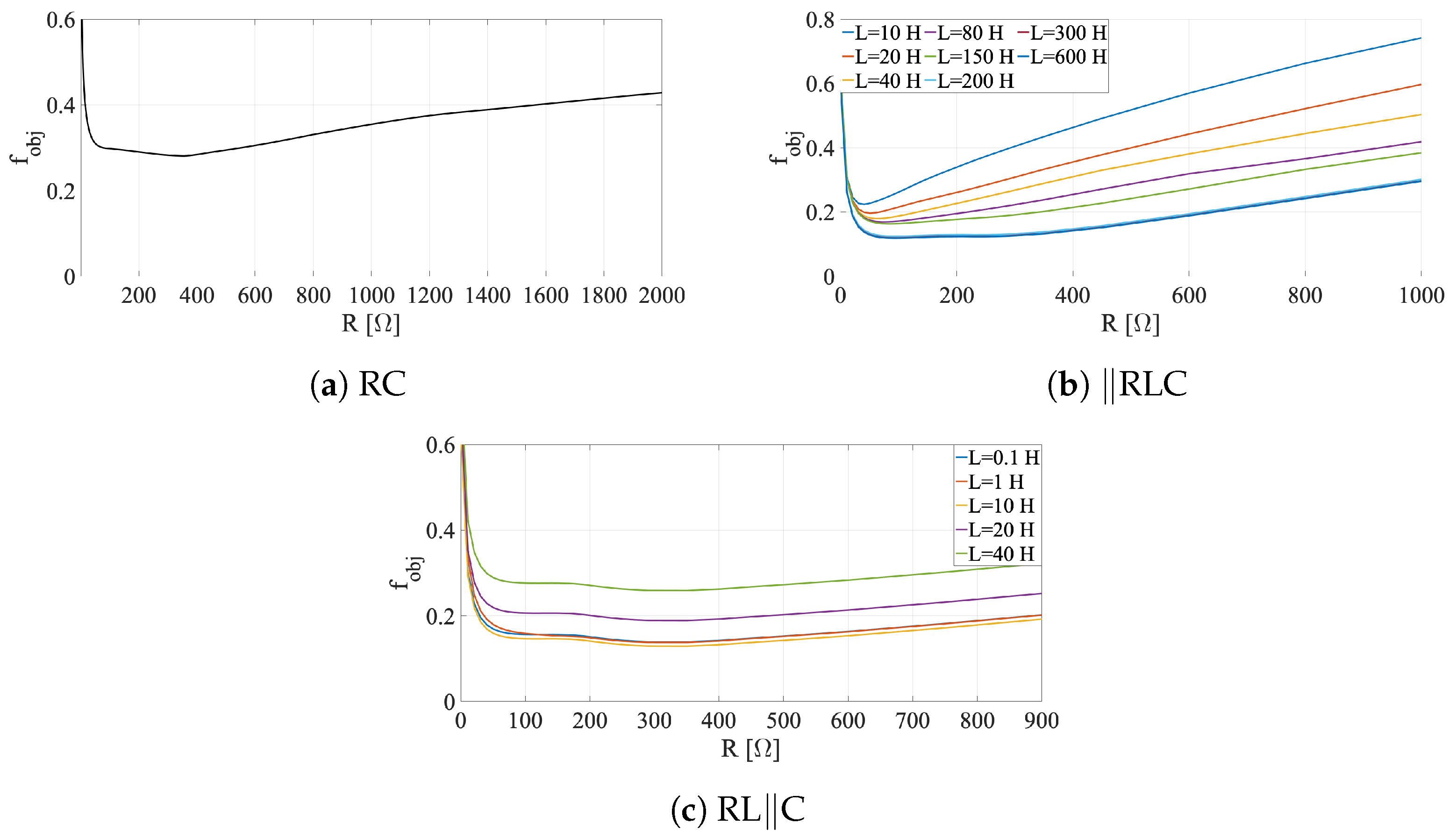
4.2. Tuning of Shunt Circuits
4.3. Tuning of the fPID Controller
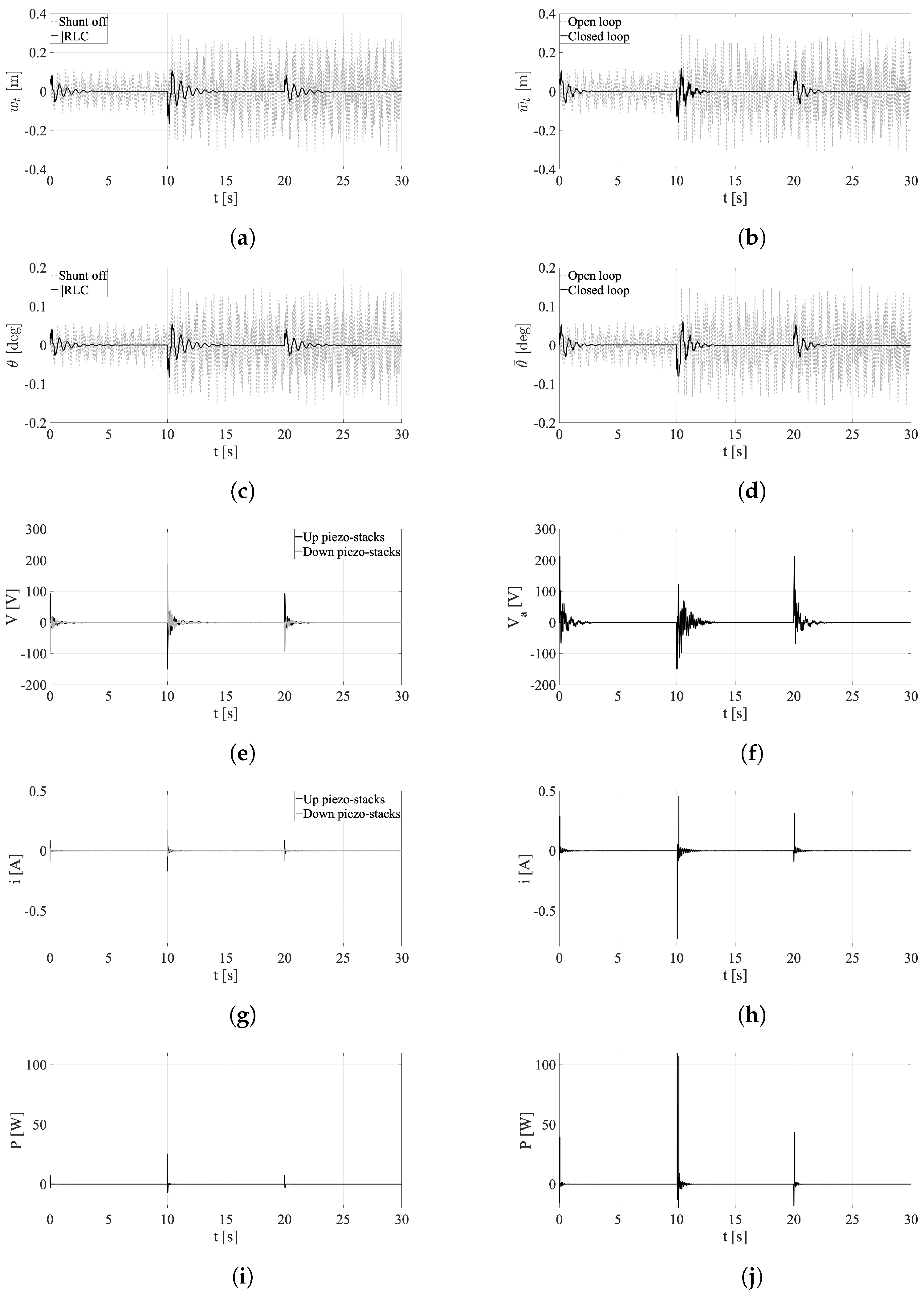
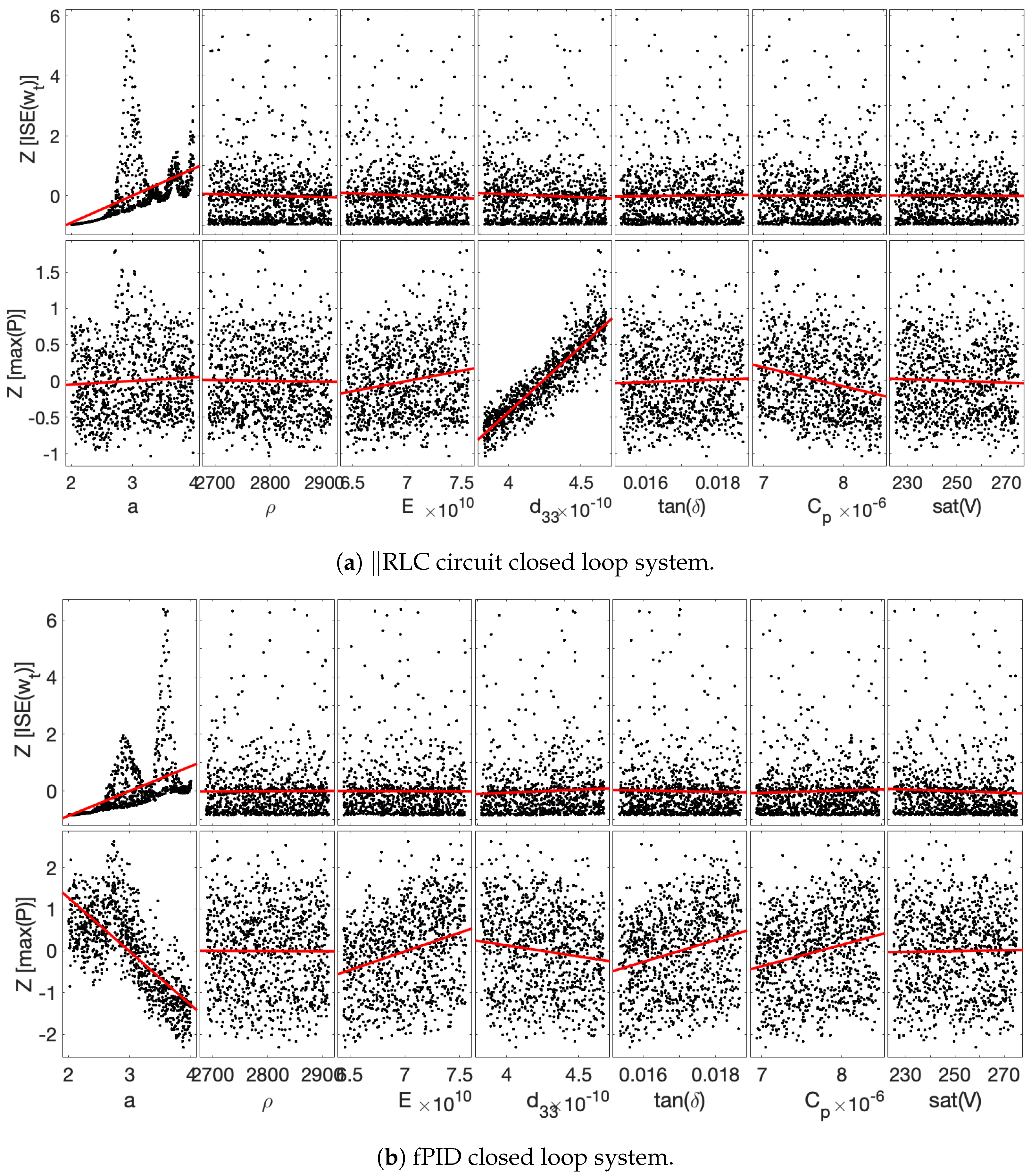
4.4. Performance Comparison
5. Conclusions
Author Contributions
Funding
Data Availability Statement
Conflicts of Interest
References
- Hyland, D.; Junkins, J.; Longman, R. Active control technology for large space structures. J. Guid. Control. Dyn. 1993, 16, 801–821. [Google Scholar]
- Hu, Q.l.; Wang, Z.; Gao, H. Sliding mode and shaped input vibration control of flexible systems. IEEE Trans. Aerosp. Electron. Syst. 2008, 44, 503–519. [Google Scholar]
- Hu, Q. Adaptive output feedback sliding-mode manoeuvring and vibration control of flexible spacecraft with input saturation. IET Control Theory Appl. 2008, 2, 467–478. [Google Scholar]
- Al-Saif, K.A.; Foda, M.A.; Aldakkan, K. Suppression of microvibrations of low-earth-orbit satellites with flexible solar panels. J. Aerosp. Eng. 2012, 25, 117–124. [Google Scholar]
- He, G.; Cao, D. Dynamic Modeling and Attitude–Vibration Cooperative Control for a Large-Scale Flexible Spacecraft. Actuators 2023, 12, 167. [Google Scholar] [CrossRef]
- Blelloch, P.; Beagley, N. Tools for analysis of control-structure interaction. Comput.-Aided Eng. J. 1990, 7, 107–112. [Google Scholar]
- Anandakrishnan, S.M.; Connor, C.T.; Lee, S.; Shade, E.; Sills, J.; Maly, J.; Pendleton, S. Hubble Space Telescope solar array damper for improving control system stability. In Proceedings of the 2000 IEEE Aerospace Conference. Proceedings (Cat. No. 00TH8484), Big Sky, MT, USA, 25 March 2000; Volume 4, pp. 261–276. [Google Scholar]
- Magliacano, D.; Viscardi, M.; Ciminello, M.; Dimino, I.; Concilio, A. Feasibility study for a tonal vibration control system of a mounting bracket for automotive gearboxes. Int. J. Mech. 2016, 10, 403–410. [Google Scholar]
- Magliacano, D.; Viscardi, M.; Dimino, I.; Concilio, A. Active vibration control by piezoceramic actuators of a car floor panel. In Proceedings of the ICSV23: 23rd International Congress on Sound and Vibration, Athens, Greece, 10–14 July 2016. [Google Scholar]
- Konovalov, S.; Kuz’menko, A. Effect of electrical circuits on duration of an acoustic pulse radiated by a piezoplate. J. Acoust. Soc. Am. 2009, 125, 1456–1460. [Google Scholar]
- Konovalov, S.; Kuz’menko, A. Influence of the electromechanical coupling coefficient of a piezoelectric plate on the acoustic pulse duration in the presence of a compensating circuit. Acoust. Phys. 2008, 54, 644. [Google Scholar]
- Allegranza, C.; Gaillard, L.; Le Letty, R.; Patti, S.; Scolamiero, L.; Toso, M. Actuators for space applications: State of the art and new technologies. In Proceedings of the 14th International Conference on New Actuators, Bremen, Germany, 23–25 June 2014; pp. 23–25. [Google Scholar]
- Hu, Q.; Ma, G. Variable structure control and active vibration suppression of flexible spacecraft during attitude maneuver. Aerosp. Sci. Technol. 2005, 9, 307–317. [Google Scholar]
- Makhtoumi, M. Active vibration control of launch vehicle on satellite using piezoelectric stack actuator. arXiv 2018, arXiv:1903.07396. [Google Scholar]
- Cao, X.; Yue, C.; Liu, M. Flexible satellite attitude maneuver via constrained torque distribution and active vibration suppression. Aerosp. Sci. Technol. 2017, 67, 387–397. [Google Scholar]
- da Fonseca, I.M.; Rade, D.A.; Goes, L.C.; de Paula Sales, T. Attitude and vibration control of a satellite containing flexible solar arrays by using reaction wheels, and piezoelectric transducers as sensors and actuators. Acta Astronaut. 2017, 139, 357–366. [Google Scholar]
- Amini, A.; Mohammadimehr, M.; Faraji, A. Active control to reduce the vibration amplitude of the solar honeycomb sandwich panels with CNTRC facesheets using piezoelectric patch sensor and actuator. Steel Compos. Struct. 2019, 32, 671–686. [Google Scholar]
- Hu, Q.; Ma, G. Variable structure maneuvering control and vibration suppression for flexible spacecraft subject to input nonlinearities. Smart Mater. Struct. 2006, 15, 1899. [Google Scholar]
- Hu, Q.; Ma, G.; Xie, L. Robust and adaptive variable structure output feedback control of uncertain systems with input nonlinearity. Automatica 2008, 44, 552–559. [Google Scholar]
- Hu, Q.; Ma, G. Spacecraft Vibration Suppression Using Variable Structure Output Feedback Control and Smart Materials. J. Vib. Acoust. 2005, 128, 221–230. Available online: https://asmedigitalcollection.asme.org/vibrationacoustics/article-pdf/128/2/221/5829540/221_1.pdf (accessed on 19 February 2025). [CrossRef]
- Sabatini, M.; Palmerini, G.B.; Gasbarri, P. Synergetic approach in attitude control of very flexible satellites by means of thrusters and PZT devices. Aerosp. Sci. Technol. 2020, 96, 105541. [Google Scholar]
- Azadi, E.; Eghtesad, M.; Fazelzadeh, S.; Azadi, M. Vibration suppression of smart nonlinear flexible appendages of a rotating satellite by using hybrid adaptive sliding mode/Lyapunov control. J. Vib. Control 2013, 19, 975–991. [Google Scholar]
- Azimi, M.; Shahravi, M.; Fard, K.M. Modeling and vibration suppression of flexible spacecraft using higher-order sandwich panel theory. Int. J. Acoust. Vib. 2017, 22, 143–151. [Google Scholar]
- Callipari, F.; Sabatini, M.; Angeletti, F.; Iannelli, P.; Gasbarri, P. Numerical modelling and experiments of a vibration suppression solution via Offset Piezoelectric Stack Actuators for space structures. In Proceedings of the International Astronautical Congress: IAC Proceedings, Dubai, United Arab Emirates, 25 October 2021; International Astronautical Federation, IAF: Paris, France, 2021; Volume 2, pp. 1–16. [Google Scholar]
- Angeletti, F.; Tortorici, D.; Laurenzi, S.; Gasbarri, P. Vibration Control of Innovative Lightweight Thermoplastic Composite Material via Smart Actuators for Aerospace Applications. Appl. Sci. 2023, 13, 9715. [Google Scholar] [CrossRef]
- Li, D.; Jiang, J.; Liu, W.; Fan, C. A new mechanism for the vibration control of large flexible space structures with embedded smart devices. IEEE/ASME Trans. Mechatron. 2014, 20, 1653–1659. [Google Scholar]
- Li, D.; Liu, W. Vibration control for the solar panels of spacecraft: Innovation methods and potential approaches. Int. J. Mech. Syst. Dyn. 2023, 3, 300–330. [Google Scholar]
- Albassam, B.A. Fast attitude maneuver of a flexible spacecraft with passive vibration control using shunted piezoelectric transducers. Int. J. Aerosp. Eng. 2019, 2019, 3162105. [Google Scholar]
- Sales, T.; Rade, D.; De Souza, L. Passive vibration control of flexible spacecraft using shunted piezoelectric transducers. Aerosp. Sci. Technol. 2013, 29, 403–412. [Google Scholar]
- Liu, C.; Li, H.; Zhang, F.; Wang, X. Improvement on the passive method based on dampers for the vibration control of spacecraft solar panels. Adv. Mech. Eng. 2022, 14, 16878132221080596. [Google Scholar]
- Vindigni, C.R.; Orlando, C. Simple adaptive V-stack piezoelectric based airfoil flutter suppression system. J. Vib. Control 2023, 29, 2802–2816. [Google Scholar]
- Ardelean, E.V.; Cole, D.G.; Clark, R.L. High Performance “V-stack” Piezoelectric Actuator. J. Intell. Mater. Syst. Struct. 2004, 15, 879–889. [Google Scholar]
- Paik, J.K.; Thayamballi, A.K.; Kim, G.S. The strength characteristics of aluminum honeycomb sandwich panels. Thin-Walled Struct. 1999, 35, 205–231. [Google Scholar]
- Joseph, T.K.; Renji, K.; Venkatraman, K. Simple Mathematical Models for the Dynamics Of Spacecraft With Deployed Solar Panels. J. Aerosp. Sci. Technol. 2014, 66, 84–95. [Google Scholar]
- Wei, J.; Cao, D.; Wang, L.; Huang, H.; Huang, W. Dynamic modeling and simulation for flexible spacecraft with flexible jointed solar panels. Int. J. Mech. Sci. 2017, 130, 558–570. [Google Scholar]
- Preumont, A. Vibration Control of Active Structures: An Introduction; Springer: Berlin/Heidelberg, Germany, 2018; Volume 246. [Google Scholar]
- Vindigni, C.R.; Orlando, C.; Milazzo, A. Computational analysis of the active control of incompressible airfoil flutter vibration using a piezoelectric v-stack actuator. Vibration 2021, 4, 369–394. [Google Scholar] [CrossRef]
- Vindigni, C.R.; Esposito, A.; Orlando, C. Stochastic aeroservoelastic analysis of a flapped airfoil. Aerosp. Sci. Technol. 2022, 131, 107967. [Google Scholar]
- Xu, R.; Li, D.; Jiang, J.; Zou, J. Decentralized adaptive fuzzy vibration control of smart gossamer space structure. J. Intell. Mater. Syst. Struct. 2017, 28, 1670–1681. [Google Scholar]
- Vindigni, C.R.; Mantegna, G.; Orlando, C.; Alaimo, A. Simple adaptive wing-aileron flutter suppression system. J. Sound Vib. 2024, 570, 118151. [Google Scholar]
- Paz, M.; Leigh, W. Structural Dynamics; Springer: Berlin/Heidelberg, Germany, 1991. [Google Scholar]
- Reddy, J.N. An Introduction to the Finite Element Method; McGraw-Hill: New York, NY, USA, 2005; Volume 3. [Google Scholar]
- Qu, Z.Q. Model Order Reduction Techniques with Applications in Finite Element Analysis; Springer Science & Business Media: Berlin/Heidelberg, Germany, 2013. [Google Scholar]
- Moheimani, S.R.; Fleming, A.J. Piezoelectric Transducers for Vibration Control and Damping; Springer Science & Business Media: Berlin/Heidelberg, Germany, 2006. [Google Scholar]
- Moheimani, S.R. A survey of recent innovations in vibration damping and control using shunted piezoelectric transducers. IEEE Trans. Control Syst. Technol. 2003, 11, 482–494. [Google Scholar]
- Caruso, G. A critical analysis of electric shunt circuits employed in piezoelectric passive vibration damping. Smart Mater. Struct. 2001, 10, 1059. [Google Scholar]
- Horowitz, P.; Hill, W.; Robinson, I. The Art of Electronics; Cambridge University Press: Cambridge, UK, 1989; Volume 2. [Google Scholar]
- Alaimo, A.; Milazzo, A.; Orlando, C. A smart composite-piezoelectric one-dimensional finite element model for vibration damping analysis. J. Intell. Mater. Syst. Struct. 2016, 27, 1362–1375. [Google Scholar]
- Lanczos, C. An iteration method for the solution of the eigenvalue problem of linear differential and integral operators. J. Res. Natl. Bur. Stand. 1950, 45, 255–282. [Google Scholar]
- Antoniou, A. Gyrators using operational amplifiers. Electron. Lett. 1967, 3, 350–352. [Google Scholar]
- Viana, F.A.C.; Steffen, V., Jr. Multimodal vibration damping through piezoelectric patches and optimal resonant shunt circuits. J. Braz. Soc. Mech. Sci. Eng. 2006, 28, 293–310. [Google Scholar]
- CTS|Ferroperm™ Piezoceramics. 2025. Available online: https://www.ferropermpiezoceramics.com/wp-content/uploads/2021/10/Datasheet-soft-pz27.pdf (accessed on 13 March 2025).
- Schuëller, G.I.; Calvi, A.; Pellissetti, M.F.; Pradlwarter, H.J.; Fransen, S.H.; Kreis, A. Uncertainty analysis of a large-scale satellite finite element model. J. Spacecr. Rocket. 2009, 46, 191–202. [Google Scholar]
- Plante, J.; Lee, B. Environmental Conditions for Space Flight Hardware: A Survey. 2005. Available online: https://ntrs.nasa.gov/api/citations/20060013394/downloads/20060013394.pdf (accessed on 13 March 2025).
- Algueró, M.; Jiménez, B.; Pardo, L. Rayleigh type behavior of the Young’s modulus of unpoled ferroelectric ceramics and its dependence on temperature. Appl. Phys. Lett. 2003, 83, 2641–2643. [Google Scholar]
- Weaver, W.; Shannon, C.E. The Mathematical Theory of Communication; University of Illinois Press: Champaign, IL, USA, 1963; Volume 517. [Google Scholar]
- Vindigni, C.R.; Mantegna, G.; Esposito, A.; Orlando, C.; Alaimo, A. Stochastic robustness analysis of wing-aileron flutter suppression systems. J. Phys. Conf. Ser. 2024, 2746, 012007. [Google Scholar] [CrossRef]
- Cover, T.M. Elements of Information Theory; John Wiley & Sons: Hoboken, NJ, USA, 1999. [Google Scholar]
- Abdi, H. Z-scores. Encycl. Meas. Stat. 2007, 3, 1055–1058. [Google Scholar]


| Parameters | Values |
|---|---|
| Satellite body | |
| Mass of the body [kg] | 150 |
| Moments of inertia [kg · m2] | 100, 100, 100 |
| Yoke | |
| Yoke length, [m] | 2 |
| Cross-section width, [m] | |
| Cross-section thickness, [m] | |
| Solar panel | |
| Length of the panel, a [m] | 2.0 |
| Width of the panel, b [m] | 2.0 |
| Distance between the hinges [m] | 1.6 |
| Honeycomb core thickness, [m] | 0.0197 |
| Sandwich surface sheets thickness, [m] | |
| Honeycomb cell length, [m] | |
| Honeycomb cell wall thickness, [m] | |
| Elastic modulus, [Pa] | |
| Density, [kg m−3] | |
| Poisson’s ratio, | 0.33 |
| Hinge stiffness, | 500 |
| Piezostack | |
| Piezostack elastic modulus, [Pa] | |
| Piezostack density, [kg m−3] | 7700 |
| Piezostack cross-section, [mm2] | |
| Piezoelectric charge coefficient, | |
| Dielectric dissipation factor, | |
| Maximum and minimum Voltage | V, V |
| Mode | ANSYS [Hz] | Present [Hz] | % Error |
|---|---|---|---|
| 1—OOP bending | 1.49 | 1.47 | 1.35% |
| 2—IP bending | 3.7 | 3.6 | 2.7% |
| 3—OOP bending | 8.67 | 8.52 | 1.7% |
| 4—torsion | 9.14 | 9.1 | 0.4% |
| 5—OOP bending | 81.54 | 80.14 | 1.7% |
| 6—IP bending | 109.1 | 107.6 | 1.4% |
| RC | ‖RLC | RL‖C | |
|---|---|---|---|
| 0.281 | 0.119 | 0.129 | |
| [] | 360 | 91 | 300 |
| [H] | − | 300 | 10 |
| 5 | ||||||||
| 10 | ||||||||
| 20 |
| Parameter | Variation Range |
|---|---|
| Solar panel length | m |
| Young’s modulus | |
| Mass density | |
| Piezoelectric stack capacity | |
| Piezoelectric charge coefficient | |
| Dielectric dissipation factor | |
| Voltage saturation |
Disclaimer/Publisher’s Note: The statements, opinions and data contained in all publications are solely those of the individual author(s) and contributor(s) and not of MDPI and/or the editor(s). MDPI and/or the editor(s) disclaim responsibility for any injury to people or property resulting from any ideas, methods, instructions or products referred to in the content. |
© 2025 by the authors. Licensee MDPI, Basel, Switzerland. This article is an open access article distributed under the terms and conditions of the Creative Commons Attribution (CC BY) license (https://creativecommons.org/licenses/by/4.0/).
Share and Cite
Vindigni, C.R.; Esposito, A.; Orlando, C.; Alaimo, A. Comparison of Piezoelectric Stack-Based Passive and Active Vibration Suppression Systems for Satellite Solar Panels. Vibration 2025, 8, 15. https://doi.org/10.3390/vibration8020015
Vindigni CR, Esposito A, Orlando C, Alaimo A. Comparison of Piezoelectric Stack-Based Passive and Active Vibration Suppression Systems for Satellite Solar Panels. Vibration. 2025; 8(2):15. https://doi.org/10.3390/vibration8020015
Chicago/Turabian StyleVindigni, Carmelo Rosario, Antonio Esposito, Calogero Orlando, and Andrea Alaimo. 2025. "Comparison of Piezoelectric Stack-Based Passive and Active Vibration Suppression Systems for Satellite Solar Panels" Vibration 8, no. 2: 15. https://doi.org/10.3390/vibration8020015
APA StyleVindigni, C. R., Esposito, A., Orlando, C., & Alaimo, A. (2025). Comparison of Piezoelectric Stack-Based Passive and Active Vibration Suppression Systems for Satellite Solar Panels. Vibration, 8(2), 15. https://doi.org/10.3390/vibration8020015