Article

Innovative Energy-Recovery Unit for the LED-Lighting System of Heavy-Duty Vehicles

by
Nena Apostolidou
1,*,
Fotis Valsamas
1,
Dimitris Baros
1,
Michael Loupis
1,2,*,
Vasilios Dasteridis
3 and
Charalampos Kokkinis
3,*
1
Innovative Technologies Center S.A., Alketou 25, 11633 Athens, Greece
2
General Department, National and Kapodistrian University of Athens, 15772 Psachna, Greece
3
Dasteri Systems S.A., 1st km Alexandroupolis-Ferron, 68133 Alexandroupolis, Greece
*
Authors to whom correspondence should be addressed.
Clean Technol. 2021, 3(3), 581-593; https://doi.org/10.3390/cleantechnol3030035
Submission received: 26 April 2021 / Revised: 23 July 2021 / Accepted: 30 July 2021 / Published: 4 August 2021

Abstract

:
In this work, the development of an energy recovery control unit to be incorporated in the light-emitting diodes (LEDs) lighting systems of heavy-duty vehicles is presented. This innovative industrial product adopts modern power electronics technology to improve existing trucks’ LED lighting system by eliminating the so far inevitable power consumption by the conventional central control unit of the majority of these vehicles, which is obligatory for the uninterruptable operation of their lighting system. The main idea of this innovative product is its capability to virtually increase the lighting system power consumption without actually consuming this amount of energy, thus facilitating the central control unit requirements regarding these vehicles in an energy-conscious way. Under this light, a mature power converter’s topology is employed to draw the proper amounts of power from the vehicle’s batteries supply, to the level that the central control unit recognizes, and return this energy back to the batteries. The tests results of the developed industrial product highlight the energy saving potential of the proposed energy recovery scheme, while the Life Cycle Cost Analysis (LCCA) results confirm its techno-economical and environmental profit for the truck applications under study.

1. Introduction

The significant advantages of LEDs over conventional incandescent and fluorescent lamps along with the smart control schemes that their development facilitates [1,2] have led to their massive incorporation in the lighting systems of the majority of heavy-duty vehicles, such as buses, trucks and lorries. However, the energy saving profit of LED technology, coming out from the direct conversion of the electric energy into light and thus avoiding large heat emissions [3,4], is incompatible with the majority of vehicles’ central control units (CCUs) under study; the extremely low power consumption of LED technology cannot be recognized as a normal operation condition by the CCUs, resulting in the assumption of faulty operation in the lighting system. This is a common malfunction concerning not only old trucks bearing lamps, but some new truck models as well. Under this light, various products have been developed to eliminate this issue, regarding the utilization of passive pseudo-load (such as ohmic resistors) connected in parallel with the lamps to increase the power consumption to recognizable levels, as shown in Figure 1. However, this results in unnecessary waste of significant amounts of energy, reducing the efficiency of trucks’ lighting systems via increasing the fuel consumption. At the same time, the vehicle battery is subjected to considerable strain which drastically decreases its lifetime, therefore leading to more frequent battery replacements. In this context, frequent battery replacement not only further increases the total cost of the lighting system, but also becomes an additional factor of environmental pollution, due to the necessity of recycling the damaged lead-acid batteries [5,6,7,8,9].
The environmental impact associated with recycling and disposal of lead-acid batteries regards not only the ambient environment, but also toxicity and human exposure; this end of product life procedure is of great concern as it is the current practice for automotive batteries [10]. Thus, the contribution of the recycling stage is critically important in assessing the environmental impact of batteries; until recycling infrastructures for many battery types are developed, disposal will remain for the majority of batteries, affecting emission levels and consequently public health. It is noted that a study of blood lead levels in people—especially children—living near a secondary smelter [11], has highlighted those public health dangers. Under this light, the prolongation of the batteries’ life/usage mitigates the battery disposal procedure, contributing to the reduction of the aforementioned environmental/public health impact.
To overcome this drawback, an innovative industrial product has been designed and developed in order to replace the conventional pseudo-load, making the LED lights compatible with trucks’ CCUs and thus enabling the massive use of LED lights in the vehicles under study. The main advantage of this new product is the drastic reduction of the power consumption in the lighting circuit, via returning the additional energy amounts of the pseudo-load back to the battery, in real time, according to Figure 2.
Figure 2 presents the schematic diagram of the developed energy recovery unit; this unit controls the LED lighting power supply from the battery bank, according to the truck driver’s commands, as well as increases—in a technical manner—the LED lighting electrical consumption at the appropriate level, only to return the redundant energy back to the battery storage. Apart from the dc/dc converter topology, the energy recovery unit also includes a programming and communication interface, which permits the set of the system parameters—such as the energy recovery power level—providing system design flexibility and the user data exchange capability—such as electric power and energy recovery measurements, hours of operation, fault signals, etc.
Apart from the direct improvement of the energy consumption of the truck’s lighting system, the energy saving benefits of this novel industrial product also regard the enhancement of safety in transportation; this is accomplished by increasing the use of environmentally-friendly LED lighting systems, and the upgrade of trucks’ driving behavior due to the expanded adoption of LED-lighting systems and the elongation of the trucks’ battery lifetime; the latter also results in the reduction of their replacement rating, which has multiple environmental benefits regarding battery recycling procedures, such as the reduction of the need for dangerous lead-acid battery waste management, the deterioration of the batteries’ polluting emissions and the battery recycling energy consumption deterioration.
The developed control scheme is based on well-known, robust modulation techniques, to form a prototype energy recovery unit, presented for the first time in literature, which highlights its novelty in the area of such industry applications. Furthermore, the developed innovative solution is flexible, plug-n-play, and thus adaptable by all types of heavy track vehicles, that is by older and modern trucks’ lighting systems, ensuring the potential drastic reduction of a serious quantity of transportation energy consumption.
The paper is organized in five more sections, apart from Introduction (Section 1). In Section 2, the firm theoretical analysis of the energy recovery circuitry and the technical specifications of the developed product are given. Furthermore, Section 3 presents the performance results of the novel product and validates the proposed energy-saving scheme. Moreover, in Section 4 the environmental and financial benefits of the incorporation of the developed product in trucks’ lighting systems are evaluated through LCCA. Finally, in Section 5 the commercial and environmental benefits of the innovative industrial product are discussed, while Section 6 summarizes the main conclusions of the present work.

2. Description of the Innovative Energy-Recovery Unit

2.1. Power Converter Topology

To implement the energy recovery scheme of Figure 2, a power electronic topology consisting of two separate converters, one Buck and one Boost converter, has been designed and employed to perform the necessary energy transaction between the battery supply system and the LED lights’ load in the most efficient way [12,13,14].
Figure 3 presents in detail the aforementioned converter topology; the two converters are connected in series to perform the virtual electrical power consumption at the circuitry input—i.e., the Buck converter’s side—and the electrical power recovery at the circuitry output—i.e., the Boost converter’s side—having negligible actual power consumption.
The virtual power consumption concept is imposed via the Pulse Width Modulation (PWM) control technique that has been selected to drive both Buck and Boost converters; more specifically, in the Buck converter case, the Peak Current Control switching strategy is selected [15,16,17], while in the Boost converter case Average Power Control technique is used [18,19,20]. This way, the appropriate switching pulses for each control strategy are applied to switches SBuck and SBoost.

2.2. Control Strategy Implementation

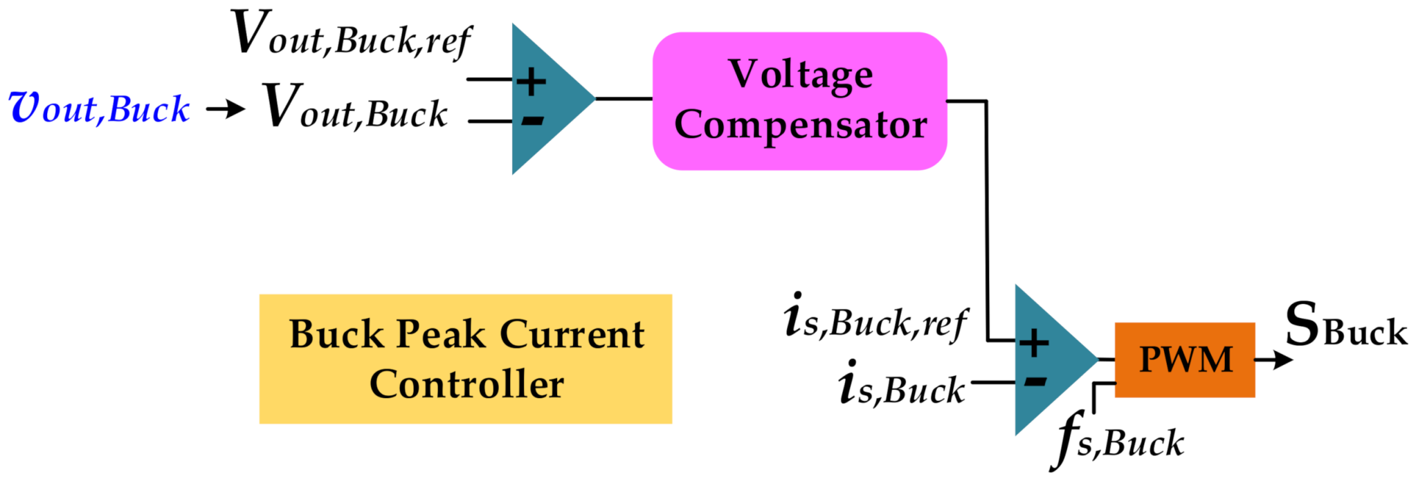
The implementation of the switching strategy in the Buck converter case involves a double control loop, comprising of an outer proportional controller—Voltage Compensator, including a comparator and an analog error amplifier—to perform the comparison of the reference and actual mean output voltage value (Vout,Buck), as well as an inner control loop, to which the error between the reference and actual values is fed. This error serves as a reference peak switching current value (iS,Buck,ref), driving the actual switching current value of SBuck (iS,Buck). This way, the appropriate pulses—using 450 kHz switching frequency in this case—to drive the converter are generated, as Figure 4 depicts.
Similarly, for the implementation of the switching strategy in the Boost converter case, a double control loop is involved, comprising of an outer proportional controller—Current Compensator, including a comparator and an analog error amplifier—to perform the comparison of the average reference and actual Boost input current values (Iin,Boost,ref and Iin,Boost respectively), as well as an inner control loop, to which the error is fed. This error serves as a reference peak switching current value (iS,Boost,ref), driving the actual switching current value of SBoost (iS,Boost). This way, the appropriate pulses—using 850 kHz switching frequency in this case– to drive the converter are generated, as Figure 5 depicts [21,22].
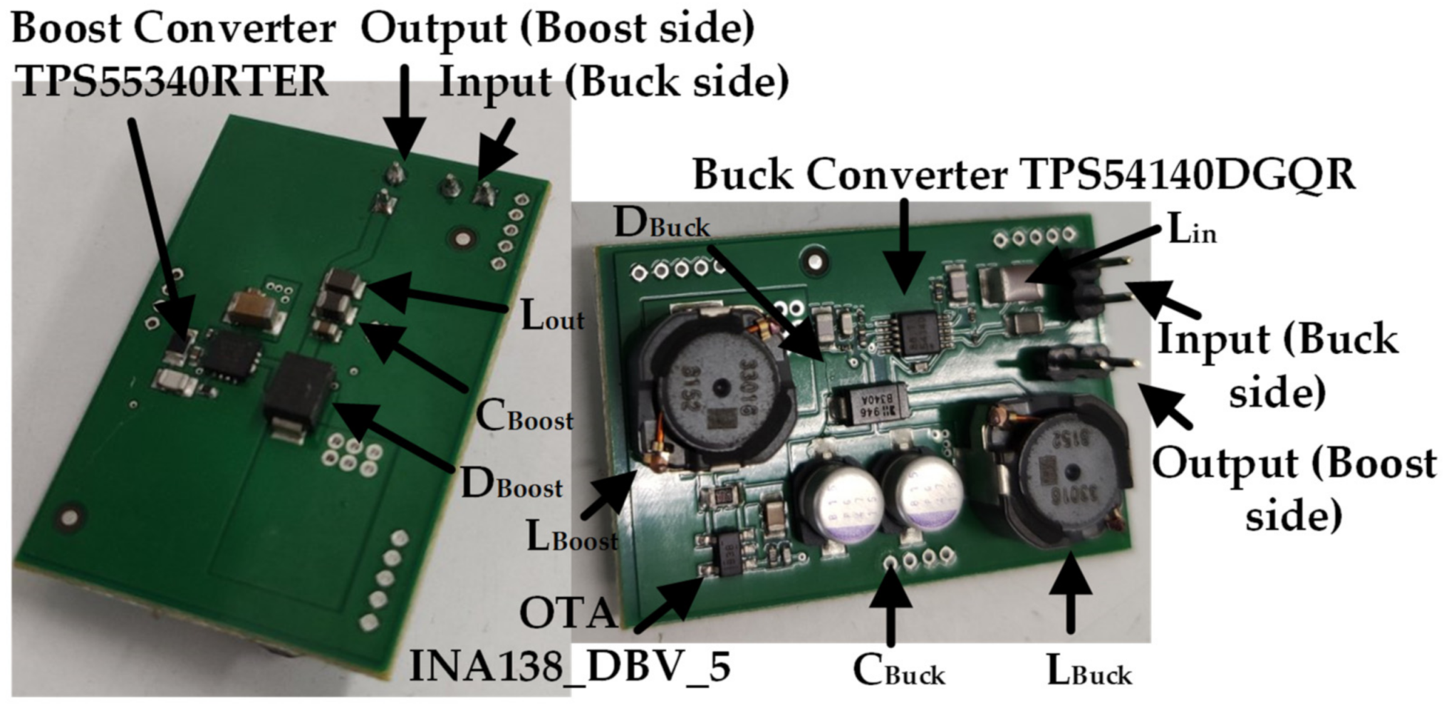
Regarding the present application, the Boost IC provides an embedded controller that implements a classical double loop peak current control, which is the same as that provided by the Buck’s converter IC. However, in order to apply our control scheme, the outer loop of Figure 5a must be converted from voltage loop to average current loop; the latter is achieved by using an Operational Transconductance Amplifier (OTA), which in our case is the INA138_DBV_5 IC [23], as illustrated in Figure 5b. The OTA converts the measured voltage signal into a current signal with a specific gain (gm); this current signal is then passed through an external resistor (RL) and the voltage drop (Vout) on this resistor drives the negative input of the outer voltage compensator, as depicted in Figure 5a. The total gain (g) of the current amplifier is affected by the selection of R and RL and is equal to R*gm*RL.
As depicted in Figure 5a, the Boost converter’s IC has an inner voltage reference (Vref,int) equal to 1.229 V, which defines the desired g of the circuitry for a specific input current value. In our case, the input average current value that results in a constant Boost converter input power is well known, since the voltage input is held constant from the Buck converter. For example, if the desired Boost IC input power (Pin,Boost) is 10 W, the desired input current is Iin,Boost = Pin/Vout,Buck = 10/9 = 1.11 A, which means that in order to convert the 1.11 A current level into 1.229 V voltage level, the required g can be calculated to the value of 1.229/1.11 = 1.1. In this way, the Boost converter’s control scheme is modified to perform the average power control.
It is noted that iS,Boost has limited ripple, thus facilitating the Average Power Control of the Boost converter; however, inductor filters (Lin, Lout) at the input and output stages of the innovative virtual load are necessary for the battery current (ib) ripple minimization. Obviously, the battery voltage level (vb) is held constant, according to the battery specifications. According to Figure 4 and Figure 5, instantaneous current feedback of both switches’ current, as well as output Buck voltage feedback (vout,Buck) and input Boost current feedback (iin,Boost) are necessary for the control scheme implementation.

3. Technical Features and Performance

3.1. Industrial Prototype

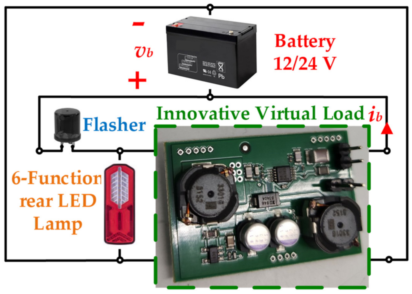
Figure 6 shows the industrial prototype of the innovative energy recovery unit, as analyzed in Section 2. The industrial prototype performance under real conditions has been validated with the use of the 6-Function rear LED lamp model of Dasteri Systems S.A. [24].
Figure 6 presents the schematic circuit of the specific truck lighting system under validation, consisting of the battery supply unit (which can be either at 12 V or at 24 V voltage level), the 6-Function rear LED lamp and the novel virtual load unit. It is noted that the Flasher component is a mechanical relay that implements the dynamic direction indication function of the specific lamp model [25]. For the hardware implementation of the designed converter topology, two industrial integrated converter modules are employed, the TPS54140DGQR (Buck converter) [26] and the TPS55340RTER (Boost converter) [27]; detailed photos of the innovative virtual load package, along with the list of its main components, can be found in Appendix A.
The main technical/design parameters of the developed energy recovery unit can be summarized as follows:
  • Recycling power (pseudo-consumption) level, 10 W (compatible with the CCU thresholds),
  • Weight, 15 g,
  • Total efficiency, over 80%,
  • High reliability, implying MTBF (Mean Time Between Failures) indicator value of 10,000 h,
  • Maximum operating temperature up to 70 °C,
  • Low cost, <0.6 €/W,
  • Plug-n-play device, and
  • Design flexibility/compatibility with all vehicle types, by allowing the implementation of various power level energy recovery scenarios via parameter management.
It is noted that the aforementioned technical characteristics highlight the developed industrial product modularity, facilitating its potential adoption in other LED lighting applications of various voltage and/or power levels.

3.2. Performance Results

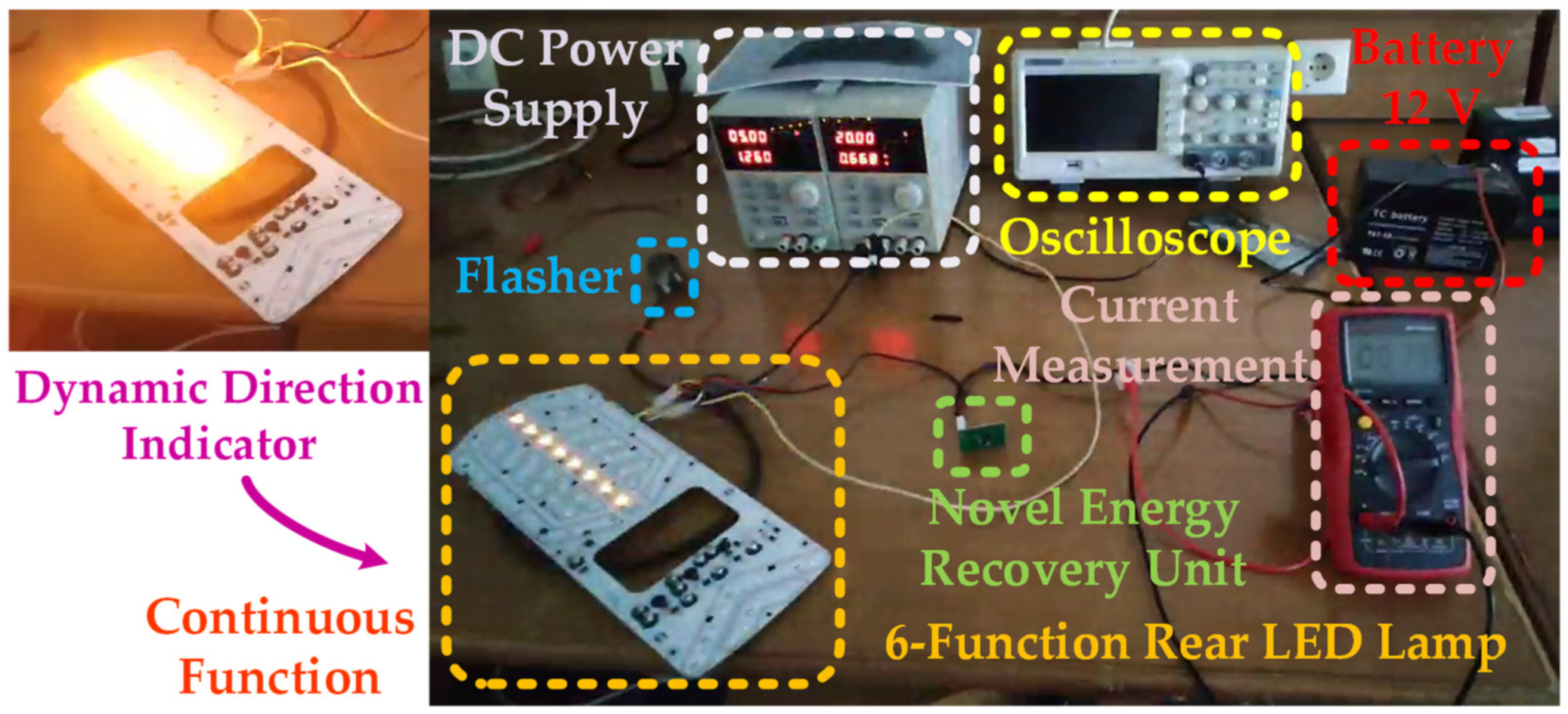
Figure 7 shows the test bench of the innovative industrial prototype, incorporated in the 6-Function rear LED lamp model of Dasteri Systems S.A.; the performance tests were implemented under two out of the six available functions of the specific lamp model, regarding the continuous as well as the dynamic direction indicator function (with the use of the Flasher). The battery supply unit is at 12 V voltage level.
Figure 8 depicts the Buck and Boost converters’ inductance voltage waveforms (i.e., Lbuck and LBoost voltages) under continuous function of the lamp, according to the set-up seen in Figure 7.
In the Buck converter case in Figure 8a, the LBuck voltage is held at the ub-vout,Buck voltage level when SBuck is on and at -vout,Buck voltage level when SBuck is off (according to the circuit in Figure 3). Similarly, in the Boost converter case in Figure 8b, LBoost voltage is at vin,Boost voltage level when SBoost is on and at the vin,Boost-vb voltage level when SBoost is off.
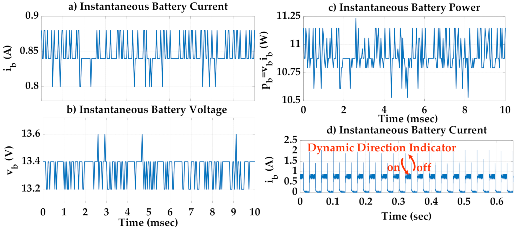
Moreover, Figure 9 presents the performance results of the innovative industrial product operation under continuous and dynamic direction indicator functions, according to the set-up seen in Figure 7.
More specifically, in Figure 9a–c the instantaneous battery current and voltage waveforms, as well as the recycled power waveform under the continuous lamp function, are depicted. In Figure 9d, the instantaneous battery current under the dynamic direction indicator function is presented, with 50/50% light on/off operation. It is noted that the total efficiency of the virtual load regarding Figure 9 results is 82%.
Furthermore, the power consumption of the LED lamp under study, as well as the passive pseudo-load and the innovative virtual load consumptions, under both continuous and dynamic direction indicator functions, have been measured; afterwards, the power consumption of the conventional and the novel industrial product, and thus the outcoming power saving, is estimated. These results are summarized in Table 1.
Table 1 results highlight the significant margin of the energy saving in heavy vehicles’ lighting systems with the incorporation of the innovative industrial product, which is up to 70% for the continuous lamp operation. These motivating results are further evaluated with the use of LCCA, which is presented in the following section.

4. Environmental and Financial Benefits

4.1. Life Cycle Cost Analysis

In order to evaluate the energy saving margin presented in Table 1 under realistic conditions of heavy-duty vehicles’ annual operation (h/y), three alternative scenarios are considered; these regard high, medium and low frequency annual operation of the vehicles, which are considered for 7000 h/y, 6000/5000 h/y and 4000 h/y driving hours, respectively. In every case, the electrical energy consumption of the lighting system is derived from diesel thermal energy consumption [28], reduced by the efficiency of the electrical generator, which is moderately considered at 80%. Moreover, the current rate prices of diesel oil for transportation purposes in Greece (refinery prices) are also considered [29].
The annual thermal energy consumption (kWhth,h) of the conventional and innovative industrial product are examined under the continuous function of the specific LED lamp model for the three aforementioned alternative scenarios of the vehicles’ operation; the results are summarized in Table 2.
From Table 2, it turns out that the annual thermal energy saving under the alternative vehicles’ operation scenarios with the adoption of the innovative industrial product is significant (up to 70% energy saving in every examined case).
Next, the initial cost of production and distribution of the innovative industrial product is estimated though current commercial components’ prices [30]; this way, the initial cost, defined as the market price of 30 €/unit, can result in the safe assessment of the payback period of the developed product. Under this light, a ten-year period LCCA has been carried out [31,32], taking into account the results of Table 2 as well as the values of the economic and time parameters in Table A2 of Appendix B. The results of the LCCA regarding the alternative vehicles’ operation scenarios are depicted in Figure 10.
Figure 10 implies that the more frequent the vehicles’ use, the more effective the energy and financial savings become; specifically, regarding the frequent usage of a heavy truck, i.e., 7000 h/y, or the medium usage of 6000 h/y, the investment (that is the innovative energy recovery unit incorporation in the truck’s lighting system) payback period turns out in less than two years, while in the case of low and medium frequency vehicle usage, 4000 h/y and 5000 h/y, respectively, the payback period is less than three years.

4.2. Battery Cycles Saving Assessment

The results of Section 4.1 (Figure 10) regarding the incorporation of the innovative industrial product in trucks’ lighting systems are promising not only in terms of the energy and financial savings for the next decade of the present analysis, but also for battery operating cycle savings, resulting in a considerable battery lifetime elongation.
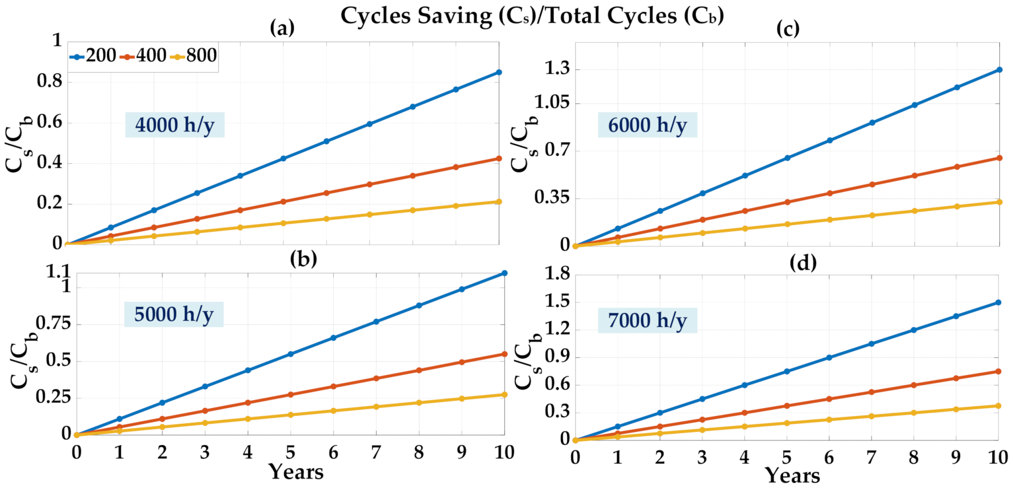
To investigate this assessment, three alternative cases of mature commercial battery technologies (dedicated to the heavy-duty vehicles under study) of 200, 400 and 800 operational cycles are considered [33,34]; once again, these batteries’ categories are evaluated under the already discussed alternative scenarios of vehicles’ usage, i.e., 4,000–7,000 h/y. Under this scope, Figure 11 depicts the number of the cycles that are saved (Cs) as a portion of the total battery operating cycles (Cb) for the ten-year period of the analysis and for each vehicle usage-case under examination.
From Figure 11, it turns out that the battery operating cycles’ savings range from the minimum 20%—regarding the advanced technology of 800 operating cycles battery, under the low-frequency vehicle usage of 4000 h/y (Figure 10a)—up to 150% (regarding the technology of 200 operating cycles battery), under the high-frequency vehicle usage of 7000 h/y (Figure 10d);
Regarding the 200 operating cycles battery case, even a total battery unit can be saved within the ten-year LCCA of the innovative energy recovery unit operation, under the 5000–7000 h/y operation scenarios, according to Figure 11b,c.

5. Discussion on the Performance and LCCA Results

The developed energy recovery unit provides an innovative solution for the drastic reduction of the energy consumption of both older and modern trucks’ lighting systems, especially when extremely low power LED lamps are used. Under this frame, the high-efficiency energy management capabilities that modern power electronics technology provides are exploited; a simple and mature DC/DC converter topology, which is controlled by the proper energy-recycling scheme, succeeds in achieving energy saving amounts up to 70%. What is more, the design flexibility of the innovative industrial product regarding its incorporation in several vehicle types further facilitates its widespread adoption.
The LCCA results (Section 4) along with the battery operating cycles’ saving potential assessment (Section 5) highlight the effectiveness of the developed energy recovery product to be incorporated in heavy-duty vehicles’ LED lighting systems. The initial cost of the innovative product is finally estimated at approximately 1.4 €/W, which for these low power applications is a tolerable expense, taking into consideration the prominent payback period; in every case of the vehicles’ annual usage, even under the moderate driving hours scenarios, the payback period turns out in less than three years, which highlights the cost-effectiveness of the innovative product.
Last but not least, the battery operating cycles’ saving hypothesis, with positive impact on the battery lifetime, further accounts for the initial commission; especially in the conventional battery case of 200 operating cycles, there is significant potential for saving a total battery unit within seven years of the innovative energy recovery unit operation; the latter can be a strong motivation, in terms of the enhancement of the trucks’ environmentally-friendly usage, via more rarely necessary battery replacement.

6. Conclusions

In the present work, the design and development of an innovative energy recovery unit dedicated to heavy-duty vehicles’ lighting systems is presented. In the first place, the main theoretical analysis of the project is described; a mature power converter topology is employed to absorb the appropriate amount of energy from the vehicles’ battery supply, in order to virtually raise the LED lighting power consumption—ensuring the unobstructed operation of the truck lighting system—and return it back to the battery unit. The developed unit’s performance tests results on an industrial lamp model proved the effectiveness of the initial energy saving concept. The LCCA results highlight the significant power/energy and financial amounts’ savings. Finally, the commercial trucks’ battery characteristics were taken into account in order to evaluate the potential battery lifetime increase resulting from this energy recovery; the latter also contributes to the reduction of lead-acid batteries’ recycling rate, with a direct positive environmental/public health impact.

7. Patents

The work reported in this manuscript is patent pending (Application Nr. 20200100205).

Author Contributions

Conceptualization, M.L. and V.D.; methodology, C.K.; software, N.A., F.V. and D.B.; validation, N.A., F.V. and D.B.; formal analysis, N.A., F.V.; investigation, D.B.; resources, V.D. and C.K.; data curation, F.V.; writing—original draft preparation, N.A.; writing—review and editing, N.A. and D.B.; visualization, F.V. and D.B.; supervision, M.L.; project administration, M.L.; funding acquisition, M.L. and V.D. All authors have read and agreed to the published version of the manuscript.

Funding

This research has been performed under the framework of Operational Program Competitiveness, Entrepreneurship and Innovation 2014–2020 (EPAnEK), regarding the project entitled ‘‘Reinforcement of secure transportation by means of an environmentally-friendly lighting system’’.

Institutional Review Board Statement

Not applicable.

Informed Consent Statement

Not applicable.

Data Availability Statement

The corresponding author can be contacted for further information and access to raw data.

Conflicts of Interest

The authors declare no conflict of interest.

Appendix A

Table A1. Main components of the energy recovery unit of Figure A1 [30].
Component Commercial ProductMTBF
Step down (Buck) converterTPS54140DGQR1.96 × 109
Step up (Boost) converterTPS55340RTER1 × 1010
Operational transconductance amplifier (OTA)INA138_DBV_54.71 × 109
Lin, Lout (1 uH)TFM201208ALD-1R0MTCA5.13 × 1010
LBuck, LBoost (33 uH)MSS1048-333MLB5.13 × 1010
DBuckB340A-13-F4.2 × 109
DBoostB340LB-13-F4.2 × 109
CBuck, CBoost (47 uF)16SVPG47M1.66 × 108
Figure A1. Novel energy recovery unit. Package dimensions: height: 10 mm, width: 39 mm, length: 27 mm.
Cleantechnol 03 00035 g0a1

Appendix B

Table A2. Economic and time parameters for the calculation method of LCCA [31,32].
Financial Parameters
Discount rate, d0%
Inflation rate, g0.30%
Cost of debit, i0%
Down payment, D100%
Escalation of energy cost, e0.50%
Time Parameters (Years)
Period analysis, N10
Loan period, NL0

References

  1. Gagliardi, G.; Casavola, A.; Lupia, M.; Cario, G.; Tedesco, F.; Lo Scudo, F.; Gaccio, F.C.; Augimeri, A. A smart city adaptive lighting system. In Proceedings of the 3rd International Conference on Fog and Mobile Edge Computing, FMEC 2018, Barcelona, Spain, 23–26 April 2018. [Google Scholar]
  2. Gagliardi, G.; Lupia, M.; Cario, G.; Tedesco, F.; Cicchello Gaccio, F.; Lo Scudo, F.; Casavola, A. Advanced Adaptive Street Lighting Systems for Smart Cities. Smart Cities 2020, 3, 1495–1512. [Google Scholar] [CrossRef]
  3. Magno, M.; Polonelli, T.; Benini, L.; Popovici, E. A low cost, highly scalable wireless sensor network solution to schieve smart LED light control for green buildings. IEEE J. Sens. 2015, 5, 2963–2973. [Google Scholar] [CrossRef]
  4. Pal, S.; Singh, B.; Shrivastava, A. A universal input CrCM Luo converter with low-cost pilot-line dimming concept for general purpose LED lighting applications. IEEE Trans. Ind. Inform. 2018, 14, 4895–4904. [Google Scholar] [CrossRef]
  5. Ruetschi, P. Aging mechanisms and service life of lead-acid batteries. J. Power Sources 2004, 127, 33–44. [Google Scholar] [CrossRef]
  6. Bindner, H.; Cronin, T.; Lundsager, P.; Manwell, J.F.; Abdulwahid, U.; Baring-Gould, I. Lifetime Modelling of Lead Acid Batteries; Risø National Laboratory Report; Risø National Laboratory: Roskilde, Denmark, 2005; p. 81. ISBN 87-550-3441-1. [Google Scholar]
  7. Sauer, D.; Wenzl, H. Comparison of different approaches for lifetime prediction of electrochemical systems-using lead-acid batteries as example. J. Power Sources 2008, 176, 534–546. [Google Scholar] [CrossRef]
  8. Voronov, S.; Frisk, E.; Krysander, M. Data-driven battery lifetime prediction and confidence estimation for heavy-duty trucks. IEEE Trans. Reliab. 2018, 67, 623–639. [Google Scholar] [CrossRef] [Green Version]
  9. Blanke, H.; Bohlen, O.; Buller, S.; De Doncker, R.W.; Fricke, B.; Hammouche, A.; Liznez, D.; Thele, M.; Sauer, D.U. Impedance measurements on lead–acid batteries for state-of-charge, state-of-health and cranking capability prognosis in electric and hybrid electric vehicles. J. Power Sources 2005, 144, 418–425. [Google Scholar] [CrossRef]
  10. Dutt, D. Life cycle analysis and recycling techniques of batteries used in renewable energy applications. In Proceedings of the International Conference on New Concepts in Smart Cities: Fostering Public and Private Alliances (SmartMILE), Gijon, Spain, 11–13 December 2013; pp. 1–7. [Google Scholar] [CrossRef]
  11. Steele, N.; Allen, D. Evaluation of recycling and disposal options for batteries. In Proceedings of the IEEE International Symposium on Electronics and the Environment (ISEE), Dallas, TX, USA, 6–8 May 1996; pp. 135–140. [Google Scholar] [CrossRef]
  12. Kim, M.; Choi, C.; Kim, S.; Jeong, D. An AC–DC LED driver with a two-parallel inverted buck topology for reducing the light flicker in lighting applications to low-risk levels. IEEE Trans. Power Electron. 2017, 32, 3879–3891. [Google Scholar] [CrossRef]
  13. Yu, W.; Lai, J.; Ma, H.; Zheng, C. High-efficiency DC–DC converter with twin bus for dimmable LED lighting. IEEE Trans. Power Electron. 2011, 26, 2095–2100. [Google Scholar] [CrossRef]
  14. Baros, D.; Voglitsis, D.; Papanikolaou, P.N.; Kyritsis, A.; Rigogiannis, N. Wireless power transfer for distributed energy sources exploitation in DC microgrids. IEEE Trans. Sustain. Energy 2018. [Google Scholar] [CrossRef]
  15. Rigogiannis, N.; Voglitsis, D.; Papanikolaou, N. Microcontroller based implementation of peak current control method in a bidirectional buck-boost DC-DC converter. In Proceedings of the International Symposium on Electrical Apparatus and Technologies (SIELA), Bourgas, Bulgaria, 3–6 June 2018; pp. 1–4. [Google Scholar] [CrossRef]
  16. Kim, M. Error amplifier design of peak current controlled (PCC) buck LED driver. IEEE Trans. Power Electron. 2014, 29, 6789–6795. [Google Scholar] [CrossRef]
  17. Rao, S.; Khan, Q.; Bang, S.; Swank, D.; Rao, A.; Mclntyre, W.; Hanumolu, P.K. A 1.2-A buck-boost LED driver with on-chip error averaged senseFET-based current sensing technique. IEEE J. Solid State Circuits 2011, 46, 2772–2783. [Google Scholar] [CrossRef]
  18. Qu, Y.; Qiu, L. I2V2 average current control for modular LED drivers. IEEE Trans. Power Electron. 2021, 36, 78–82. [Google Scholar] [CrossRef]
  19. Horsky, P.; Plojhar, J.; Daniel, J. Adaptive peak average current control LED driver for automotive lighting. In Proceedings of the IEEE European Solid State Circuits Conference (ESSCIRC), Cracow, Poland, 23–26 September 2019; pp. 1–4. [Google Scholar] [CrossRef]
  20. Hallworth, M.; Shirsavar, S.A. Microcontroller-based peak current mode control using digital slope compensation. IEEE Trans. Power Electron. 2012, 27, 3340–3351. [Google Scholar] [CrossRef]
  21. Poley, R.; Shirsavar, A. Digital Peak Current Mode Control with Slope Compensation Using the TMS320F2803x. Texas Instruments Application Report (SPRABE7A). 2012. Available online: https://e2e.ti.com/cfs-file/__key/communityserver-discussions-components-files/171/Digital-Peak-Current-Mode-Control-With-Slope-Compensation-Using-the-TMS320F2803x.pdf (accessed on 29 March 2021).
  22. Sheehan, R. Understanding and applying current-mode control theory. In Proceedings of the Power Electronics Technology Exhibition and Conference, Dallas, TX, USA, 30 October–1 November 2007. [Google Scholar]
  23. Available online: https://www.ti.com/lit/ds/symlink/ina168.pdf?ts=1627027982166&ref_url=https%253A%252F%252Fwww.google.com%252F (accessed on 29 March 2021).
  24. Available online: https://dasteri.gr/en/products/show/&tid=534 (accessed on 29 March 2021).
  25. Available online: https://www.ika-germany.de/wp-content/uploads/Automotive-Electronics-and-Relays-2019-Compressed-Cover.pdf (accessed on 29 March 2021).
  26. Available online: https://www.ti.com/lit/ds/symlink/tps54140.pdf?ts=1618072108253&ref_url=https%253A%252F%252Fwww.ti.com%252Fproduct%252FTPS54140 (accessed on 29 March 2021).
  27. Available online: https://www.ti.com/lit/ds/symlink/tps55340.pdf?HQS=dis-mous-null-mousermode-dsf-pf-null-wwe&ts=1618072276073&ref_url=https%253A%252F%252Fgr.mouser.com%252F (accessed on 29 March 2021).
  28. Available online: http://library.tee.gr/digital/m2600/m2600_efthimiadis.pdf (accessed on 29 March 2021).
  29. Available online: http://oil.gge.gov.gr/ (accessed on 29 March 2021).
  30. Available online: http://gr.mouser.com (accessed on 29 March 2021).
  31. Kotarela, F.; Kyritsis, A.; Papanikolaou, N. On the Implementation of the Nearly Zero Energy Building Concept for Jointly Acting Renewables Self- Consumers in Mediterranean Climate Conditions. Energies 2020, 13, 1032. [Google Scholar] [CrossRef] [Green Version]
  32. Kotarela, F.; Kyritsis, A.; Papanikolaou, N.; Kalogirou, S.A. Enhanced nZEB concept incorporating a sustainable Grid Support Scheme. Renew. Energy 2021, 169, 714–725. [Google Scholar] [CrossRef]
  33. Available online: https://batteryworld.varta-automotive.com/en-gb (accessed on 29 March 2021).
  34. Available online: https://www.varta-automotive.com/en-gb/products/varta-promotive-agm (accessed on 29 March 2021).
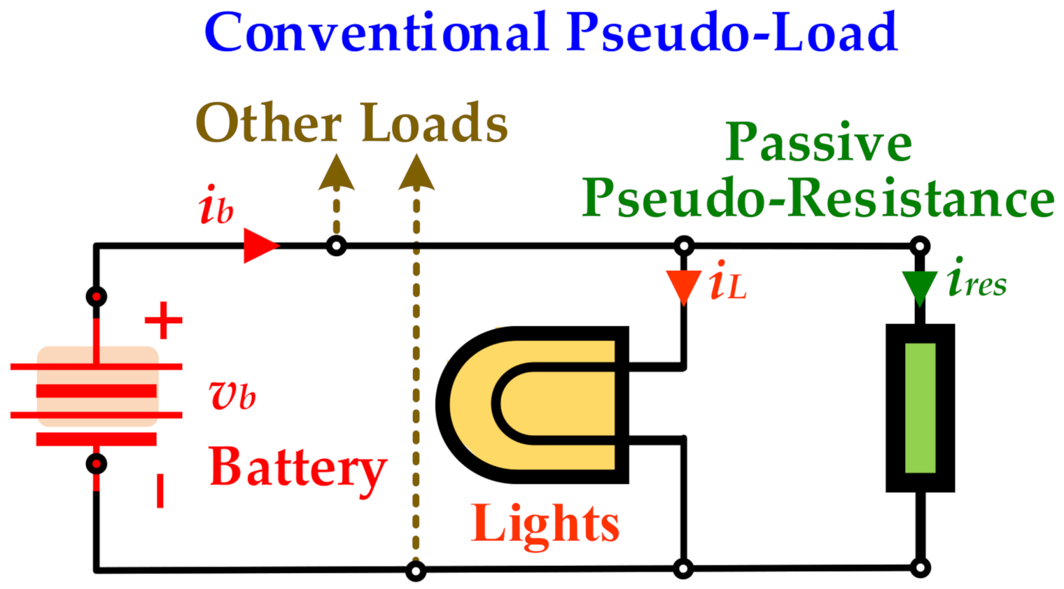
Figure 1. Conservative Pseudo-Loads incorporated in heavy-duty vehicles LED lighting system.
Cleantechnol 03 00035 g001
Figure 2. Novel energy recovery unit to be incorporated in heavy-duty vehicles’ LED lighting system.
Cleantechnol 03 00035 g002
Figure 3. Innovative virtual load topology, incorporating one Step-Down (Buck) and one Step-Up (Boost) converter topology; symbols are in accordance with Table A1 Appendix A.
Cleantechnol 03 00035 g003
Figure 4. Control scheme of the Buck converter. Peak Current Control implementation.
Cleantechnol 03 00035 g004
Figure 5. Control scheme of the Boost converter; (a) Average Power Control implementation. (b) OTA application IC.
Cleantechnol 03 00035 g005
Figure 6. Industrial prototype of the innovative energy recovery unit, incorporated in the 6-Function rear LED lamp model of Dasteri Systems S.A.
Cleantechnol 03 00035 g006
Figure 7. Test bench of the innovative industrial prototype incorporated in the 6-Function rear LED lamp model of Dasteri Systems S.A. Continuous and dynamic direction indicator operation.
Cleantechnol 03 00035 g007
Figure 8. Buck and Boost’s inductance voltages (i.e., Lbuck and LBoost voltages) under continuous function, for a 12 V battery voltage level.
Cleantechnol 03 00035 g008
Figure 9. Real-time results regarding the novel industrial prototype incorporated in the 6-Function rear LED lamp under real conditions performance test; (a) instantaneous battery current under continuous function, (b) instantaneous battery voltage under continuous function, (c) instantaneous battery recycled power under continuous function, and (d) instantaneous battery current under dynamic direction indicator function.
Cleantechnol 03 00035 g009
Figure 10. LCCA of the innovative industrial product regarding a ten-year period; (a) 4000 h/y, (b) 5000 h/y, (c) 6000 h/y, (d) 7000 h/y.
Cleantechnol 03 00035 g010
Figure 11. Number of the cycles that are saved (Cs) as a portion of the total battery operating cycles (Cb), for the ten-year period of the analysis; (a) 4000 h/y, (b) 5000 h/y, (c) 6000 h/y, (d) 7000 h/y.
Cleantechnol 03 00035 g011
Table 1. Power consumption of the LED lamp, and the conventional and the innovative industrial product. Power saving level under both continuous and dynamic direction indicator functions.
LED Lamp consumption (W)3.21.8
Passive/Virtual load consumption (W)12.8/1.656.4/1.48
Total Conventional/Innovative product consumption (W)16/4.858/3.08
Energy saving (%)7065
Table 2. Annual thermal energy consumption of the conventional and the innovative industrial product, under alternative scenarios of vehicles’ operation: high (7000 h/y), medium (6000 and 5000 h/y) and low (4000 h/y) annual driving hours.
Driving
h/y
Consumption
kWhth,h/y
Consumption
lt/y
Saving
ConventionalInnovativeConventionalInnovativekWhth,h/y%
4000 20060.6216.8 5.09139.37570
500025075.78216.37174.29
6000300 90.9325.217.64209.063
7000350106.0929.418.915243.907
Publisher’s Note: MDPI stays neutral with regard to jurisdictional claims in published maps and institutional affiliations.