Article

Aggressiveness of Different Ageing Conditions for Three Thick Marine Epoxy Systems

1
LaSIE UMR CNRS 7356, La Rochelle Université, Av. Michel Crépeau, 17042 La Rochelle, France
2
Naval Group, Technocampus Océan, 5 rue de l’Halbrane, 44340 Bouguenais, France
3
General Electric, 11 rue Arthur III-CS 86325, CEDEX 2, 44263 Nantes, France
4
Chantiers de l’Atlantique, BD de la Légion d’Honneur, 44600 Saint-Nazaire, France
5
IRT Jules Verne, CHEM Chaffault, Le Chaffault, 44340 Bouguenais, France
*
Author to whom correspondence should be addressed.
Corros. Mater. Degrad. 2021, 2(4), 721-742; https://doi.org/10.3390/cmd2040039
Submission received: 30 September 2021 / Revised: 22 November 2021 / Accepted: 30 November 2021 / Published: 3 December 2021

Abstract

:
Three different coated steel systems were aged in natural or artificial seawater, in neutral salt spray (NSS), and using alternate immersion tests in order to evaluate the aggressiveness of the different ageing conditions. Commercial epoxy coatings were applied onto steel (S355NL), hot-galvanized steel (HDG), and Zn-Al15 thermal spraying coated steel. The defect-free systems were immersed in artificial seawater at 35 °C for 1085 days and in natural seawater for 1200 days and were characterized by electrochemical impedance spectroscopy (EIS). Panels with artificial defects were immersed for 180 days in artificial seawater and, regarding adhesion, were evaluated according to ISO 16276-2. In parallel, the three coated systems were submitted to cyclic neutral salt spray (NSS) for 1440 h: defect-free panels were regularly evaluated by EIS, while the degree or corrosion was measured onto panels with artificial defect. After NSS, defect-free panels were immersed in artificial seawater at 35 °C for further EIS investigations. Finally, alternate immersion tests were performed for 860 days for the three defect-free coated systems and for 84 days for panels with a defect. The results showed that, for defect-free panels, immersions in natural or artificial seawater and NSS did not allowed us to distinguish the three different systems that show excellent anticorrosion properties. However, during the alternate immersion test, the organic coating system applied onto HDG presented blisters, showing a greater sensitivity to this test than the two other systems. For panels with a defect, NSS allowed to age the coatings more rapidly than monotone conditions, and the coating system applied onto steel presented the highest degree of corrosion. Meanwhile, the coating systems applied onto HDG and the thermal spray metallic coating showed similar behavior. During the alternate immersion test, the three coated systems with a defect showed clearly different behaviors, therefore it was possible to rank the three systems. Finally, it appeared that the alternate immersion test was the most aggressive condition. It was then proposed that a realistic thermal cycling and an artificial defect are needed when performing ageing tests of thick marine organic coating systems in order to properly rank/evaluate the different systems.

1. Introduction

The sea is a potentially huge source of energy, but the development of Marine Renewable Energy (MRE) technologies able to harness that energy is at a relatively early stage [1]. Part of the problem is that seawater is an aggressive medium, and that metallic structures are submitted to corrosion. An effective solution to protect against corrosion is organic coatings [2,3] which can be applied with high thicknesses and/or can be associated with cathodic protection [4]. Among them, epoxy-based marine coatings have been widely applied for the anticorrosion of metallic materials due to their low cost and their efficiency in aggressive mediums such as seawater [5,6]. However, all organic coating formulations have to be tested before being applied in order to offer a guarantee in terms of lifetime and effectiveness [7] because they suffer from degradation from the environment. In the past, much research has been devoted to evaluating the performance of organic coatings using natural or artificial tests [2,8,9,10,11,12,13,14,15,16].
Because anticorrosive coatings for marine environment are usually very robust, accelerated ageing tests are needed in order to promote the coating degradation. The physicochemical properties of the coatings are monitored during these tests, and many fields in material chemistry and physics are involved [17]. The coatings are often tested using standardized methods, such as the salt fog, the climatic chamber, the Q-UV chamber, thermal cycling, etc., and, in some cases, a combination of these methods is proposed. Many accelerated ageing cycles are used in practice to try to find a balance between various tests and obtain the most natural possible exposition [18]; however, very often, there is not a good correlation between accelerated ageing tests and degradation in a natural environment [19]. Research is still in progress in order to find reliable protocols and/or techniques to better understand organic coating degradation [20,21,22,23,24,25,26,27,28,29]. However, it is necessary to keep in mind that the degradation mechanisms have to be the same as the real life conditions [30], and that only the intensity of the degradation factors (temperature, humidity, UV radiation, mechanical stresses, etc.) can be increased, respecting the limit properties of the organic material. It is known that the continuous salt fog test is unrealistic [30,31,32], and a recent work showed that it did not correlate with other tests [33]. On the other hand, a simple UV-accelerated test is not sufficient to simulate the natural exposure and it is important to study the synergic effect of different accelerated factors (for example, UV radiation plus thermal cycling) on many different types of organic coatings [10,32]. In fact, fast temperature changes with high humidity and low humidity periods appear as the most harmful accelerated ageing conditions [9,12,34]. Recently, Qu et al. [35] used different wetting and drying cycles for the ageing of a coating system constituted by a thick epoxy primer and an acrylic polyurethane topcoat. They found that, the longer the wetting time in one cycle, the more serious the degradation of the coating samples. For offshore applications, organic coatings can be tested according to ISO 20340 standard, which alternates UV/condensation (ISO 11507), neutral salt spray (ISO9227), and a freezing phase (−20 °C), with a total duration of 4200 h. However, Le Bozec et al. [33] showed that there was no impact from the freezing phase and that the ISO 20340 cycle showed a satisfying correlation with test variants where UV/condensation was replaced by a wet and dry transition at a similar temperature. Davalos-Monteiro et al. [36] also compared ISO 20340 conditions to natural exposure testing, but attempts to correlate natural exposure results with cyclic test results proved unsuccessful. The authors highlighted the requirement of performing further research to provide an indication of whether a correlation with natural exposure might or might not be possible.
As one can see, the perfect accelerated ageing test that fully represents service conditions may not exist because of the very numerous factors that have to be considered, including the chemical nature of organic coatings. However, attempts to find realistic ageing conditions that one allow to accelerate the coating degradation and to rank different systems must be undertaken [37]. This work aimed to study the ageing of an epoxy coating system applied onto three different metallic substrates, using different ageing tests in natural or artificial seawater, neutral salt spray, and an alternate immersion test, in order to evaluate the aggressiveness of the different ageing conditions. Coated systems with and without initial artificial defect were considered and monotonous ageing conditions were compared to cyclic ageing conditions in order to define the most aggressive ageing condition for thick marine epoxy coatings. The evaluation of the coating degradation was performed by visual inspection (corrosion degree ISO 4628-8) for panels with defect and by electrochemical characterization (barrier properties, ISO 16773) for defect-free panels.

2. Experimental Part

2.1. Materials

Organic coatings were applied onto steel panels (S355NL) by airless spraying process under controlled climatic conditions, according to ISO 8502-4 standard by Cryo-West company (Trignac, France). The panel size was 150 mm × 100 mm × 5 mm. Three different surface preparations were used: steel panels (S355NL) submitted to blast-cleaning (Sa 2.5 according to ISO 8501-1 standard; Cryo-West company, Trignac, France), steel panels (S355NL) coated by a hot-galvanized layer (200 µm thick; France Galva company, Carquefou, France) and steel panels (S355NL) coated by a Zn-Al15 thermal spaying coat (150 µm thick; Cryo-West company, Trignac, France). Commercial paints (Hempel company, Trignac, France) were used and applied as presented in Table 1. Hempadur 45,703 is an epoxy-polyamide primer, Hempadur 45,753 is an epoxy-polyamide/amine primer and Hempadur 15,570 is an epoxy/polyamide adduct paint.
All coatings were dried at ambient air for at least 14 days, according to the technical specifications. For panels submitted to electrochemical measurements (electrochemical impedance spectroscopy, or EIS), a hole (diameter 2 mm) was drilled in the top edge of the panel and a metallic wire was inserted. The electrical connection was then embedded in a polyurethane resin to avoid moisture (Figure 1).

2.2. Ageing Tests

Defect-free samples were immersed in natural seawater (Port des Minimes, La Rochelle, France) for 1200 days (29,000 h). Samples were regularly brought back to the laboratory for EIS measurements in order to evaluate the barrier properties of the organic coating systems, according to ISO 16773 standard. Six identical panels (ROX1nat to ROX6nat; RG1nat to RG6nat; RM1nat to RM6nat) were tested for reproducibility.
Defect-free samples were also immersed in the laboratory at a controlled temperature, using NaCl 35 g·L−1 solution for 1085 days (26,000 h). The ageing temperature was 35 °C in order to accelerate degradation mechanisms but without damaging the polymer. Actually, the glass transition temperature Tg was measured by DSC measurements (DSC Q100, TA Instruments, New Castle, DC, USA) for each organic coating and was higher than 65 °C. Even with moisture ingress and a decrease in Tg, which is usually about 20 °C due to plasticization [38,39], the ageing temperature is well below the humid Tg. Moreover, artificial seawater was not chosen in order to avoid the presence of Ca2+ and Mg2+ ions, which leads to the formation of calcareous deposits [40,41] onto uncoated metallic surfaces. As RM and RG systems present a zinc layer under the organic coatings, the steel substrate is cathodically polarized in case of a defect in the organic coating and the calcareous deposit can delay the degradation of the substrate/coating interface for RM and RG systems, which is not the case for the ROX system, therefore a comparison between the different systems is not possible. Finally, six identical defect-free panels (ROX1 to ROX6; RG1 to RG6; RM1 to RM6) were tested for reproducibility.
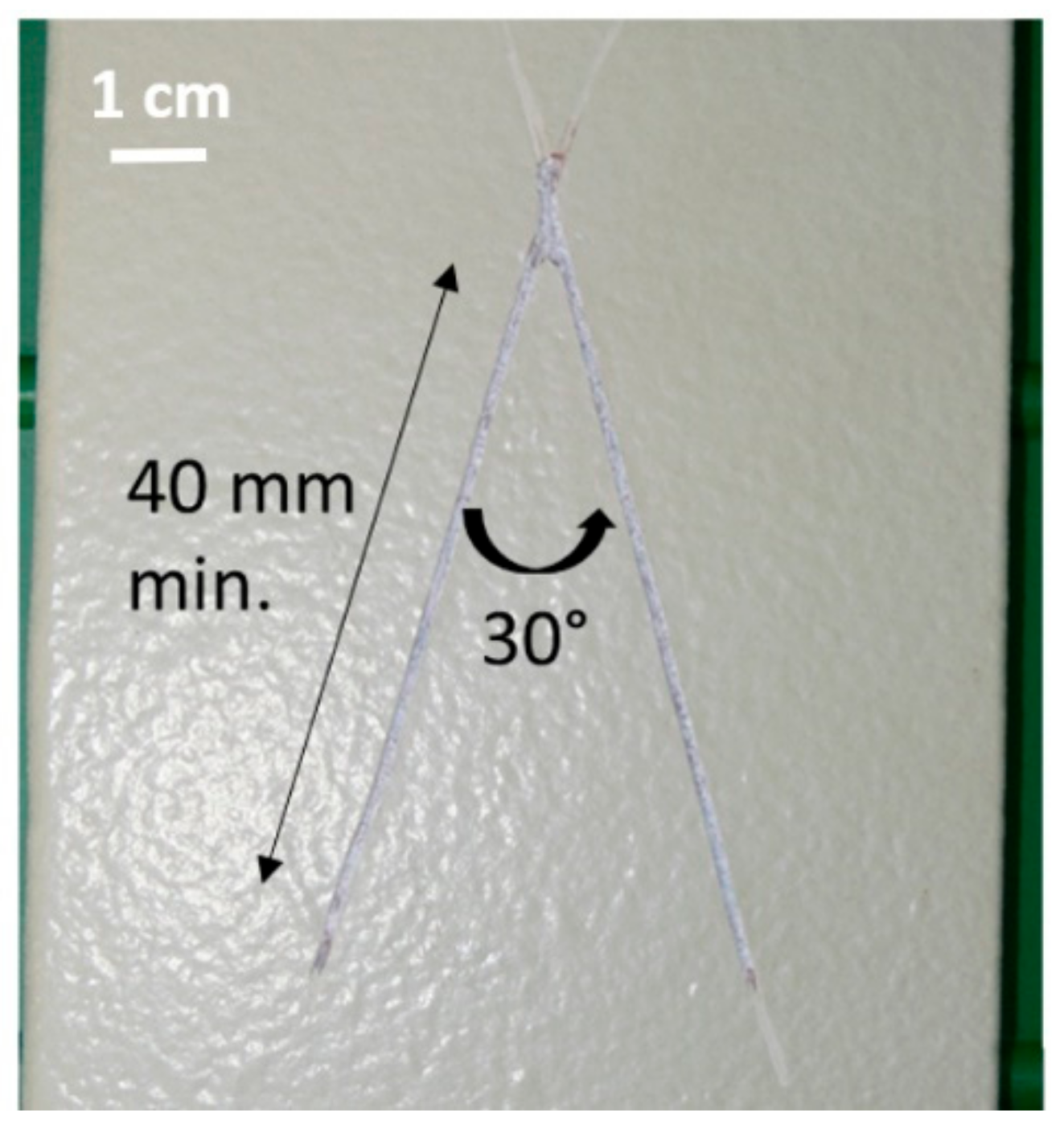
For each system, a defect (X-cut panels according to ISO 16272-2 standard) was created through the organic coating system till the metallic surface. The defect was a V shape, realized with a scribe (ISO 2409 standard) with Elcometer 1538 (40 mm length, two scribes with a 30° angle, Figure 2). The panels were then immersed in NaCl 35 g·L−1 solution for 181 days (4344 h) at 35 °C. Regularly, the samples were taken out and the degree of corrosion was evaluated according to ISO 4628-8 standard. Six identical defect-free panels for each system were tested for reproducibility.
Defect-free and X-cut panels were submitted to cyclic neutral salt spray (ASCOTT CC450IP, LABOMAT, France) for 60 days (1440 h). The cycle A from ISO 11997-1 standard was applied and is constituted as: 2 h of salt spray at 35 °C + 4 h of a dry period (20–30% Relative Humidity RH) at 60 °C + 2 h of a humid period (RH > 95%) at 50 °C. Four identical defect-free panels were evaluated by EIS measurements every week and, after 60 days, they were immersed in NaCl 35 g·L−1 solution for further EIS investigations. Four identical X-cut panels were also tested for 60 days with the cyclic neutral salt spray and the degree of corrosion was regularly evaluated.
Alternate immersion tests were also performed to better simulate marine environment. The coated samples were immersed in NaCl 35 g·L−1 solution in a glass vessel that was inserted in a climatic chamber (model WK 180/40, WEISS TECHNIK, Martillac, France) for thermal cycling for 5 days: 24 h at 5 °C then 24 h at 50 °C then 24 h at 5 °C then 24 h at 50 °C and finally 24 h at 5 °C. After 5 days, the samples were removed from the solution and placed in the climatic chamber for 2 days at 50 °C and 98%RH. The total duration for the alternate immersion test was at least 20,000 h. Every week, EIS measurements were performed with 6 identical defect-free panels and the degree of corrosion was evaluated for 4 identical X-cut panels.

2.3. EIS Measurements

Electrochemical impedance spectroscopy (EIS) measurements were performed in NaCl 35 g·L−1 solution using a REF600 potentiostat and a Paint Test Cell PTC1 (16 cm2) from GAMRY (GAMRY, Warminster PA, USA), with a calomel reference electrode and a graphite counter electrode. Defect-free coated panels with the PTC1 cell were placed in an oven (acting as a Faraday cage) at 35 °C for at least 30 min before EIS measurement so that all EIS data were obtained at 35 °C and the different ageing conditions can be compared. The frequency domain was swept from 200 kHz down to 50 mHz, with a 30 mV RMS perturbation at the free corrosion potential and 11 points per decade. From EIS spectra, the low frequency (0.1 Hz) impedance modulus |Z|0.1 Hz was measured and divided by the coating thickness e to obtain the reduced impedance modulus |Z|0.1 Hz/e that allowed to us compare samples with different thicknesses. From the high-frequency domain, the capacitance of the organic coating system Cf was calculated as:
C f = 1 2 π f · Z i
where f is 10 kHz and Z i is the imaginary part of the impedance. Then, the water uptake was calculated with the well-known Brasher and Kingsbury [42] equation, where one considers the volume fraction of pigment [43]:
χ V % = 1 f P v · log C f t C f t = 0 log ε w
where ε w is the water permittivity, f P v is the volume fraction of the pigment ( f P v = 0.46 ) , C f t is the measured capacitance at time t, and C f t = 0 is the measured capacitance at initial time.
All the results are presented as function of the reduced time τ = t i m e e (s1/2·cm−1) in order to remove the thickness effect [44,45] and to compare results obtained from samples with different thicknesses.

2.4. Degree of Corrosion

X-cut samples were regularly removed from the ageing test and observed with a microscope USB CONRAD DP-M14 camera (CONRAD, Haubourdin, France). Then, the pictures were analyzed using the software ImageJ to measure the mean scribe width (at least 6 points).

3. Results and Discussion

3.1. Thickness Measurements

Before applying the PTC1 cell onto the defect-free panels for EIS measurements, thickness (at least 10 points) was measured using an Elcometer gauge (Elcometer, La Chapelle Saint Mesmin, France) in order to find a zone with a homogeneous thickness, since EIS measurements can be greatly affected by a thickness gradient [46,47]. The mean thicknesses are given in Table 2.
These experimental values are quite different from the expected thickness about 500–550 µm (cf. Table 1) since thicknesses higher than 700 µm are frequently found. This relates the difficulty to obtain homogeneous thicknesses onto small surfaces with industrial process. It is also a strong proof that the thickness influence has to be removed from the considered parameters in order to compare all the systems.

3.2. Defect-Free Samples Immersed at 35 °C

EIS raw data obtained every 1 h for 50 h for panel ROX5 are shown in Figure 3. A one-time constant R/C behavior is clearly obtained with a capacitive domain in the high frequency region (phase values near −90°) and a resistive domain (phase values tending to 0°) for lower frequencies. The same typical behavior was obtained for other ROX panels and also for RM and RG systems.
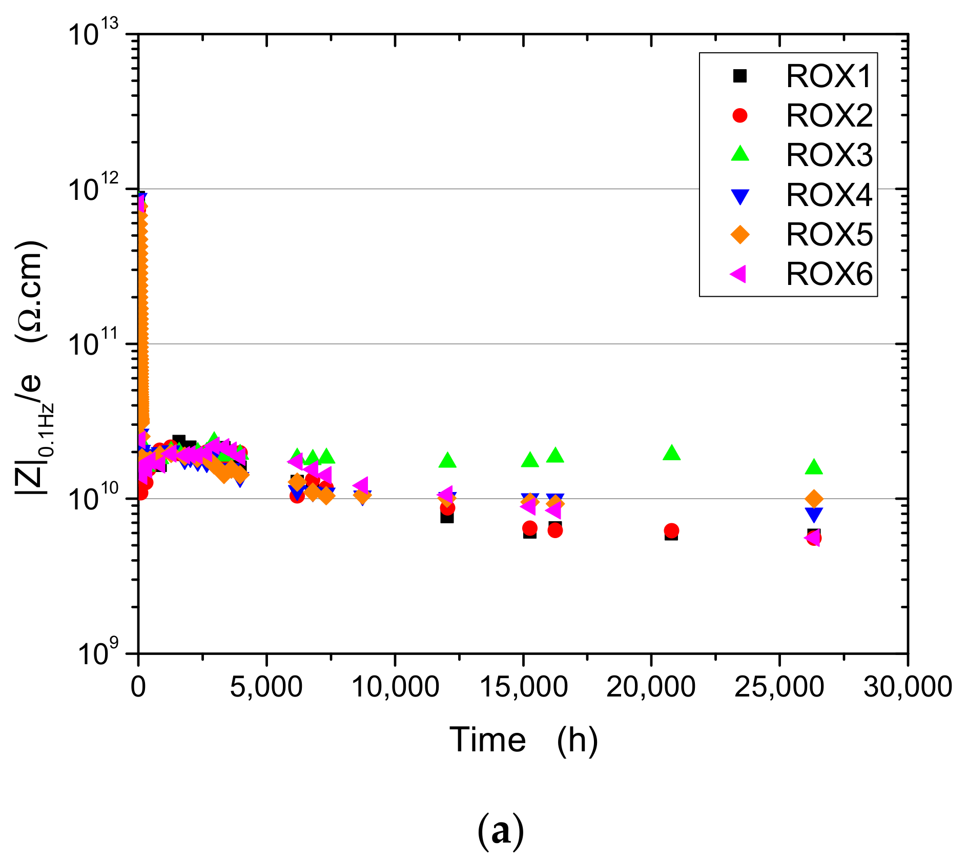
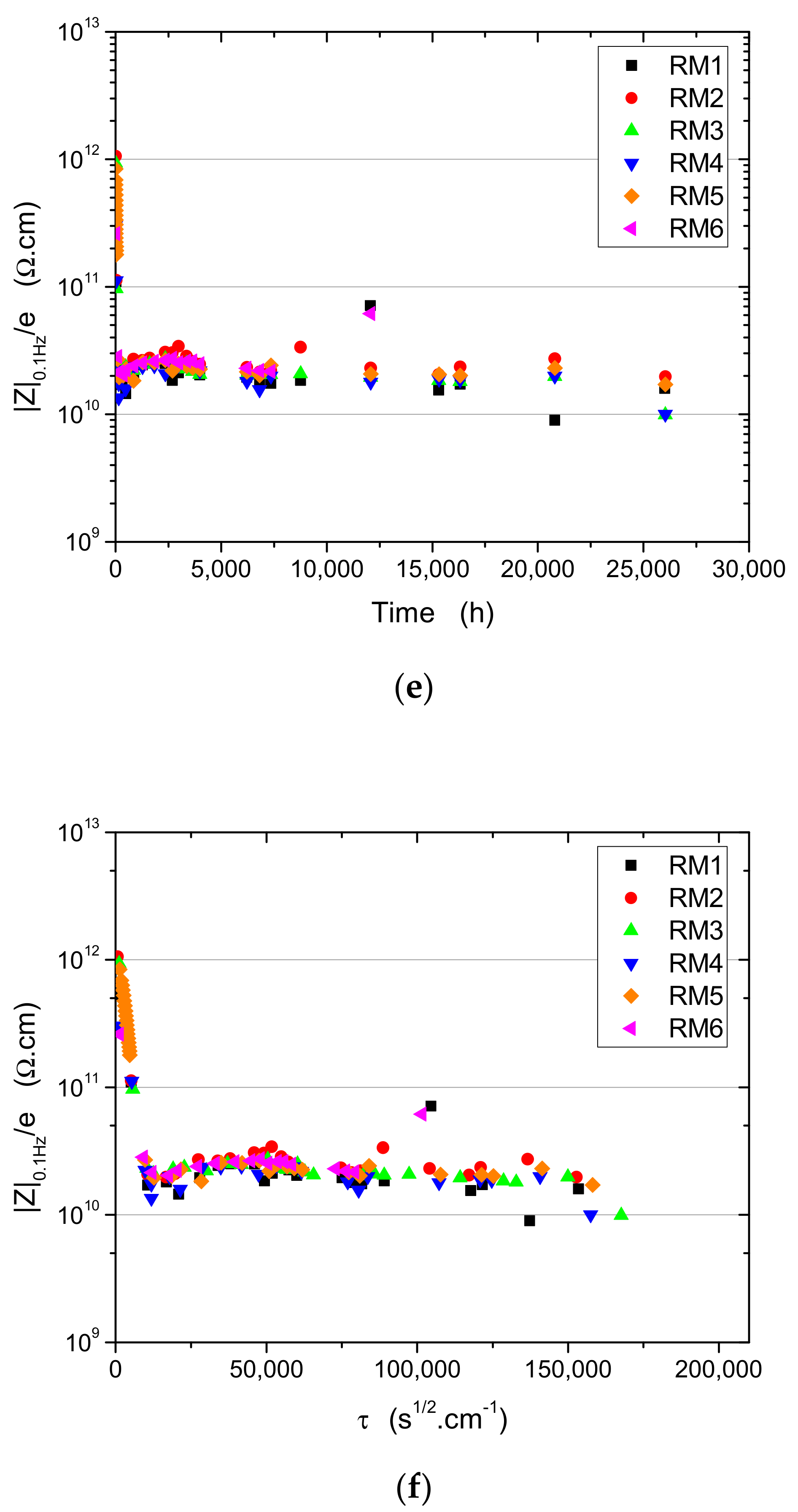
This shows a rapid decrease in the barrier effect of the organic coating system due to water uptake and a decrease in the low frequency impedance modulus |Z|0.1 Hz [8,48]. In the high frequency domain, the capacitive behavior indicates that the impedance value is dominated by its imaginary part, therefore the film capacitance C f can be readily calculated using Equation (1). Figure 4 presents the reduced low-frequency impedance modulus evolution with ageing time for ROX, RG, and RM systems.
For the three systems, the six identical panels show a very good reproducibility. For all systems, there is a rapid decrease in |Z|0.1 Hz/e, about two decades after one week, which means a decrease in the barrier effect due to water ingress. The decrease in |Z|0.1 Hz/e is the consequence of the progressive penetration of the electrolyte in the polymeric network and through resistive paths (pores, microscopic defects), which increases the conductivity of the organic layers [49,50]. The electrochemical behavior of the paint, which is highly capacitive at the beginning of the immersion period, becomes significantly resistive in the low frequency domain. Such behavior is typical for defect-free organic coatings exposed to aqueous electrolytes and has been widely described in the literature [51,52,53].
Then, for the ROX system, the reduced modulus values slightly increase before tending to a plateau, and final values are close to 10 GΩ·cm (5 × 10⁸ Ω·cm2) for 26,000 h of immersion (1085 days). These three different periods can be better seen when the reduced modulus is plotted vs. the reduced time. For RG panels, after the initial decrease in |Z|0.1 Hz/e from 1 TΩ·cm to 10 GΩ·cm, there is a long increase up to 50 GΩ·cm and a slight decrease after 20,000 h of immersion, with final values of about 30 GΩ·cm (1.5 × 10⁹ Ω·cm2) for 26,000 h of immersion (1085 days). For RM systems, a slight increase in the reduced modulus is observed after the initial decrease, similar to ROX system, except the values remain quite constant afterwards, with final values close to 20 GΩ·cm (109 Ω·cm2) for 26,000 h of immersion (1085 days). This can be explained by the presence of the additional coat onto RM systems (Table 1). For all systems, the slight increase in the reduced modulus value can be explained by a post-reticulation process [54,55] of the polymer matrix that enhances the barrier effect. Moreover, the porosity or the microscopic defects of the organic layers may be partially blocked by the swelling of the matrix or by the generation of few corrosion products [56,57]. The main observation is that, for the considered immersion period (1085 days), the coating systems present similar high impedance values that do not allow us to differentiate them, and all systems can be ranked as excellent, according to [12].
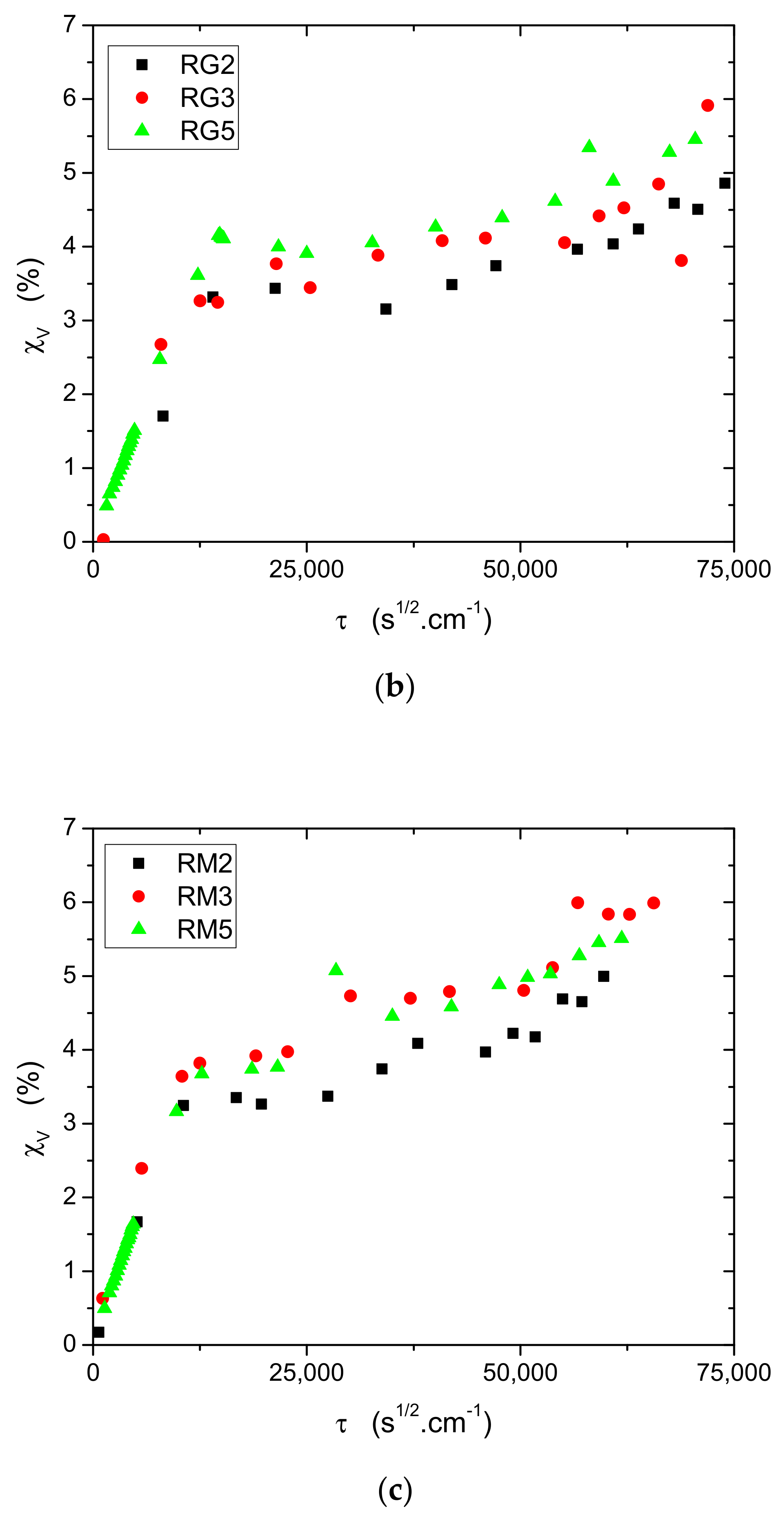
Water uptake values were calculated according to Equation (2) and plotted vs. the reduced time (Figure 5). For each system, the volume water uptake values are reproducible and are quite similar for all the systems for the ageing period. For all systems, the volume water uptake increases until 12,000 s1/2·cm−1 (about 7 days), which perfectly corresponds to the decrease in the reduced impedance modulus previously observed (Figure 4). Then, the values remain quite constant until 25,000 s1/2·cm−1 (about 30 days), with values between 3.5 and 4%, showing a pseudo-Fickian behavior. After the plateau, one can observed a slight increase that could be related to the presence of water at the pigment/polymer interface, paint delamination, swelling, or water accumulation in the coating in a heterogeneous way [58,59,60]. Indeed, the long-term water uptake of the samples may be associated with the swelling of the organic layers, increasing the thickness of the coating systems, and therefore the overall impedance, as previously discussed. Such behavior is in good accordance with many results described in the literature obtained on model epoxy coatings [61], as well as on commercial organic paints [62,63,64]. The main result is that all systems absorb similar water content, which is not surprising, since the same coating formulations are applied onto the metallic panels.
From these EIS measurements, it appears that the three systems behave quite similarly and that the immersion at 35 °C for 1085 days does not allow one to observe significant degradation and/or difference between the three systems. The same observation was made by other authors for epoxy coatings tested in aerated ASTM solution for 2 years of testing [65].

3.3. Defect-Free Samples Immersed in Natural Seawater

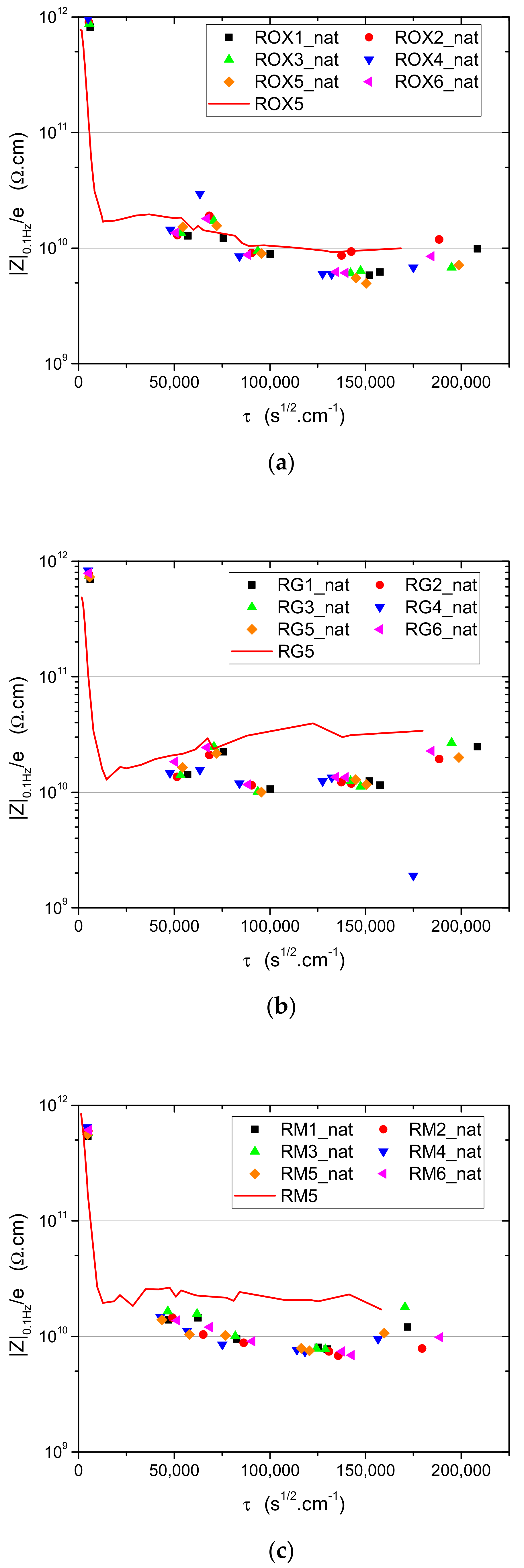
The evolution of the reduced impedance modulus for panels immersed in natural seawater is presented in Figure 6. For each system, a typical curve obtained for the same system from the ageing at 35 °C in laboratory is added to the plot for comparison with natural conditions.
Initial impedance modulus values are high, but they rapidly decrease with ageing time, as for the ageing at 35 °C in laboratory. For the three systems, the reduced impedance modulus slightly decreases with ageing time, showing final values that are globally lower than those observed during ageing at 35 °C. This can be explained by the low natural thermal cycles [2] that induce internal stresses [22,34,66,67] within the coating, leading to a faster decrease in the barrier efficiency. The main result is that the three systems behave quite similarly and that the natural immersion for 1200 days does not allow one to observe the significant degradation and/or difference between the three systems. The same observation was made by other authors for epoxy coatings tested for 7 months in natural seawater [8].

3.4. Defect-Free Samples in Cyclic NSS then Immersed at 35 °C

The evolution of the reduced impedance modulus for panels submitted to cyclic NSS is presented in Figure 7. For each system, a typical curve obtained for the same system from the ageing at 35 °C in laboratory is added to the plot for comparison with cyclic NSS conditions.
EIS measurements performed show high constant impedance values (>1 TΩ·cm ie) (|Z|0.1 Hz ≈ 50 GΩ·cm2) for all systems during the cyclic NSS period (1440 h). This means that the barrier effect is not modified by the cyclic ageing conditions and can be easily explained by the dry period at 60 °C that deletes the water uptake, as has been already mentioned by other studies [68]. Moreover, no defect (blister and/or delamination) was visually observed. It can therefore be concluded that much more time is needed to observe an eventual degradation of the coating using the cyclic NSS. After this initial period in cyclic NSS, panels were placed at 35 °C in NaCl solution. With this constant immersion, the reduced impedance modulus values decrease, showing a decrease in the barrier efficiency induced by water uptake. For the RG system, the final values of |Z|0.1 Hz/e are similar to those observed during constant immersion at 35 °C, while, for the RM and ROX systems, the final values are higher.
The initial period in cyclic NSS contains a dry period at 60 °C, which is close to the Tg value (between 65 °C and 70 °C) of the systems. In such conditions, post-reticulation and/or physical ageing [69,70,71,72] processes can take place and modify the polymer network, leading to a lower water uptake and then to a better barrier effect. That was observed for the ROX and RM systems, which are constituted by the same coating formulations, but not for the RG system. In fact, the RG system is constituted by another primer that could be more sensitive to thermal effects, leading to a lower barrier effect. Unfortunately, it was not possible to emphasize the thermal sensitivity of this primer in this work, since only coated panels were available from the industrial partners and not the paint formulations. Still, it is worth noting that, despite their relatively low thickness compared to the overall system, primers play a key role in the durability of protective paints. Indeed, the performance and the stability of the primer govern the quality of the adhesion between the metallic substrate and the coating system, which is essential to prevent and limits the propagation of corrosion. Many scientific papers have reported the importance of the adhesion regarding the durability of protective systems, and it can be improved thanks to several surface pretreatments [73,74] or through the use of the appropriate primer [75,76]. In the present case, the step at 60 °C from the NSS may deteriorate the primer and/or the interface between the primer and the substrate, leading to a loss of adhesion at the expense of the barrier properties.

3.5. Defect-Free Samples in Alternate Cycling

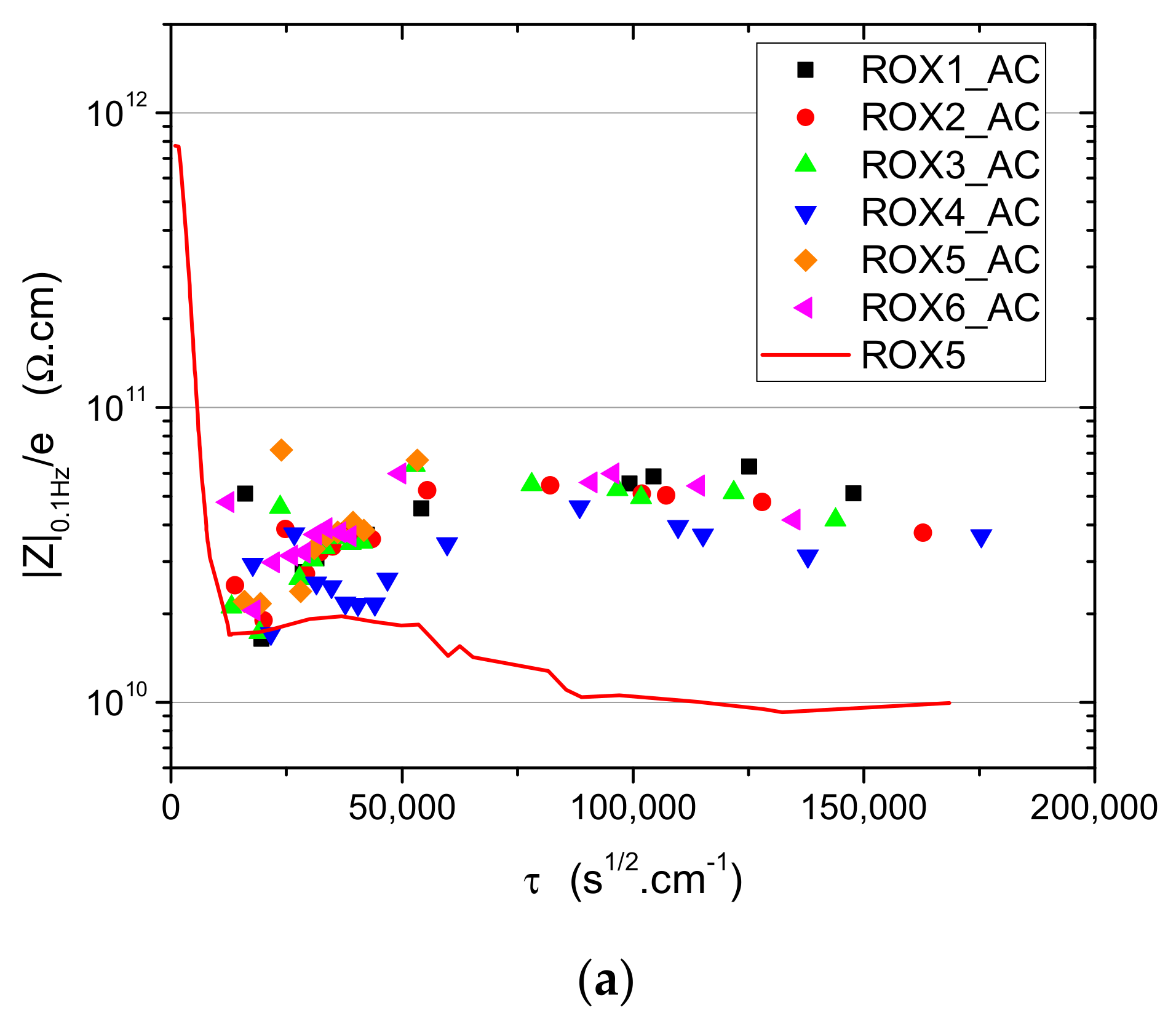
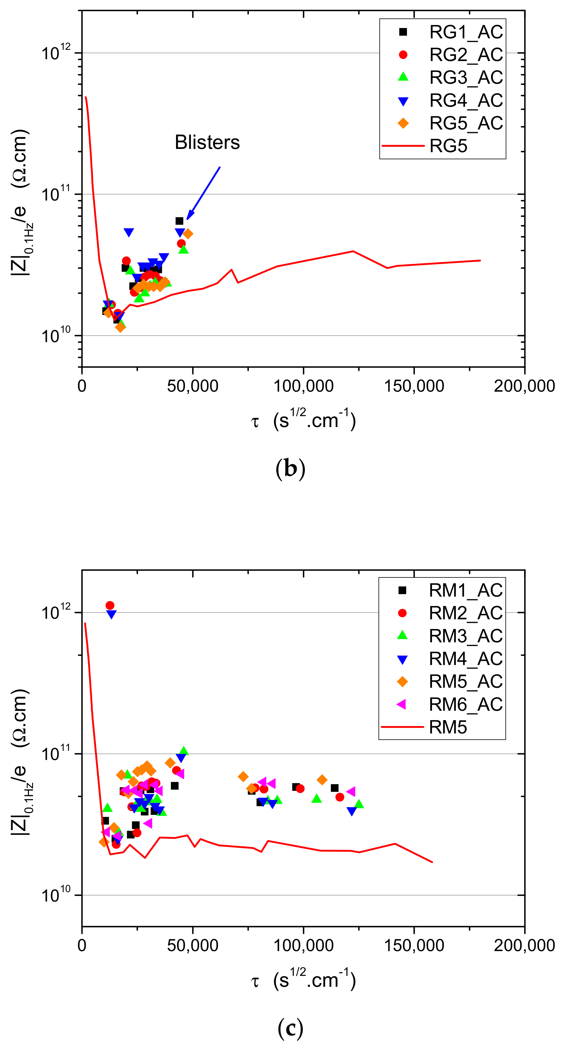
The evolution of the reduced impedance modulus for panels submitted to alternate cycling is presented in Figure 8. For each system, a typical curve obtained for the same system from the ageing at 35 °C in a laboratory is added to the plot for comparison with alternate cycling conditions.
For almost all coated panels, the reduced impedance modulus values drastically decrease after one week of the alternate cycling conditions. This is a strong difference with cyclic NSS, where a dry period was maintained for 4 h at 60 °C. In the alternate cycling conditions, the panels are either immersed or in contact with air at a relative humidity higher than 98%. In such conditions, no removal of the water uptake is expected, therefore the barrier effect decreases. After this initial decrease, the reduced impedance modulus slightly increases and tends to plateau with values higher than those observed with the immersion at 35 °C in NaCl solution. Again, thermal cycling seems to enhance the barrier effect, which can be explained, as done previously, by post-reticulation and/or physical ageing processes. If the ROX and RM systems present similar reduced impedance modulus values during the whole ageing period, the RG system rapidly presented some important blisters showing the significant degradation of the organic coating system. With such observations, the test was stopped for the RG system.
As previously seen with cyclic NSS, the RG system appears to be particularly sensitive to thermal cycling in humid conditions. The appearance of blisters confirms the loss of adhesion that was previously suspected for the RG samples exposed to NSS. Moreover, it confirms the fact that higher ageing temperatures may favor the loss of adhesion. Alternate cycling was able to request the Achilles heel of the system and to show a clear difference between RG samples and the other systems. This difference, which was already suspected from NSS results, is much more significant with alternate cycling. It may be due to the longer periods, where samples are exposed to high humidity combined with high temperature, and to the higher temperature amplitude during this test, inducing stresses at the interface between the paint system and the substrate. The same conclusions were obtained by others studies dealing with thermal cycling [30,32,77]. Unfortunately, it seems that more time is needed with these ageing conditions to differentiate the ROX and RM systems.

3.6. X-Cut Samples Immersed at 35 °C

The evolution of the corrosion degree for the three systems immersed at 35 °C in NaCl solution is presented in Figure 9. For each system, the presented curve is the mean curve obtained from six identical panels.
For the RM and RG systems, the corrosion degree values slightly increase and are quite similar for both systems, with values lower than 0.3 after 180 days of immersion. For the ROX system, the corrosion degree increases more rapidly, with values close to 0.8 after 180 days of immersion. These results show that the ROX system is less performant than the RM and RG systems, where zinc layers are deposited onto the steel substrate. It can be reminded that no specific surface treatment was applied onto the steel substrate before applying the organic coatings, which can explain such results. In these ageing conditions, and for X-cut samples, the contribution of the sacrificial layers (galvanized or thermal sprayed) and their ability to limit the propagation of corrosion are emphasized, as has been already shown by other studies [78,79], while the quality of the paint system (adhesion, barrier properties) is less crucial.

3.7. X-Cut Samples in Cyclic NSS

The evolution of the corrosion degree for the three systems submitted to cyclic NSS is presented in Figure 10. For each system, the presented curve is the mean curve obtained from four identical panels.
For RM and RG systems, the corrosion degree values slightly increase and are quite similar for both systems, with values lower than 0.3 after 1440 h (60 days) of ageing. For the ROX system, the corrosion degree increases more rapidly, with values close to 0.6 after 60 days of cyclic NSS. These results show again that the ROX system is less performant than RM and RG systems, for which no clear difference can be made after 1440 h of cycling NSS. In the same manner as immersion in NaCl, the NSS test emphasizes the contribution of the Zn-based sacrificial layers. These results are in agreement with previous studies [80] that showed that metallic Zn-based coatings increased the time for the appearance of reddish corrosion products in the edges and incision during the salt spray chamber test.

3.8. X-Cut Samples in Alternate Cycling

The evolution of the corrosion degree for the three systems submitted to alternate cycling is presented in Figure 11. For each system, the presented curve is the mean curve obtained from four identical panels.
With the alternate cycling, the three systems clearly present different behaviors. Again, the ROX system presents a more rapid increase in the corrosion degree, with values at 0.35 after 2064 h (86 days). For the RM system, the corrosion degree slightly increases and remains close to 0.07, while the RG system presents an intermediate behavior until 79 days, and drastically degrades afterwards, with a large delamination of the coating, therefore the test had to be stopped. As seen previously with defect-free panels, the RG system appears to be particularly sensitive to humid thermal cycles, especially regarding adhesion.
The alternate cycling applied to X-cut panels was then able to emphasize the contribution of the sacrificial layers in the same way as immersion in NaCl or NSS testing, but also to highlight the fragility of the adhesion, as it was observed on defect-free samples. Among the ageing conditions presented in this work, the alternate cycling should then be the preferred test to fully discriminate different paint systems, as it involves corrosion and delamination phenomena.

4. Conclusions

From the results of this work, the following conclusions can be proposed about the efficiency of the different ageing tests to differentiate the behaviors of thick marine coatings applied onto steel (ROX system), hot-galvanized steel (RG), and Zn-Al15 thermal spraying coated steel (RM):
When applied to defect-free samples, immersion tests in NaCl 35 g·L−1 solution at a constant temperature (35 °C) were only able to show the decrease in the paint resistivity for all systems. No significant difference was observed between the three systems after 1085 days of immersion. Much more time or lower thicknesses may be needed in such tests to expect degradation and eventual differentiation between different systems. When X-cut samples were immersed in NaCl, only the contribution of the sacrificial Zn layers has been shown.
The immersion in natural seawater for 1200 days showed no significant difference for the three systems. This test with true natural conditions is therefore not adapted for the rapid evaluation of thick coating performances.
No significant difference was observed between the defect-free systems during the cyclic NSS test for 1440 h. Only adhesion issues could have been suspected from these ageing conditions, but the phenomena were not clear enough. For panels with defects, the NSS cyclic test was clearly able to show the effect of the sacrificial Zn layers in the same way as the immersion tests.
When applied to defect-free panels, the alternate cycling test was able to clearly emphasize adhesion issues between the paint system and the substrate, as it has been seen with the blistering of RG samples. Moreover, when applied to X-cut panels, corrosion propagation was also involved, and this test allowed us to highlight the contribution of sacrificial Zn layers, as observed in the RM systems.
Thermal cycling is the only test which has been able to clearly differentiate defect-free systems by stressing the adhesion of the coatings. However, care must be taken when defining the thermal cycles so that the maximum temperature remains lower than the wet glass transition temperature. Finally, in the framework of this study, for thick, highly pigmented coatings, X-cut panels and alternate cycling have been the only ageing conditions to fully discriminate different paint systems by involving both corrosion and adhesion loss mechanisms. It can be noted that a long testing time is still needed to rank different thick organic coating systems, therefore more studies have to be performed in order to find rapid realistic ageing conditions. For example, steps of exposition to UV-light could also be introduced in the ageing cycles in order to induce the chemical degradation of the organic compounds and bring the testing to a more realistic level. Mechanical stresses should also be considered, depending on the targeted applications.
Further investigations should also be carried out to study paints applied on other metals, and to understand the degradation of more complex systems such as paints containing corrosion inhibitors or self-healing coatings.

Author Contributions

Investigation, A.R., V.P., J.G. and T.S.; resources, C.P.-L.; writing—original draft preparation, T.S.; writing—review and editing, A.R. and T.S.; supervision, S.F., M.K., A.-M.G.; project administration, L.F. All authors have read and agreed to the published version of the manuscript.

Funding

This research was funded by IRT Jules Verne (French Institute in Research and Technology in Advanced Manufacturing Technologies for Composite, Metallic and Hybrid Structures).

Institutional Review Board Statement

Not applicable.

Informed Consent Statement

Not applicable.

Data Availability Statement

Not applicable.

Acknowledgments

This study was part of the ADUSCOR project managed by IRT Jules Verne (French Institute in Research and Technology in Advanced Manufacturing Technologies for Composite, Metallic and Hybrid Structures). The authors wish to associate the partners of this project, respectively NAVAL GROUP, CHANTIERS DE L’ATLANTIQUE, GENERAL ELECTRIC, CETIM and IRT JULES VERNE.

Conflicts of Interest

The authors declare no conflict of interest.

References

  1. Borthwick, A.G.L. Marine Renewable Energy Seascape. Engineering 2016, 2, 69–78. [Google Scholar] [CrossRef] [Green Version]
  2. Fredj, N.; Cohendoz, S.; Feaugas, X.; Touzain, S. Ageing of marine coating in natural and artificial seawater under mechanical stresses. Prog. Org. Coat. 2012, 74, 391–399. [Google Scholar] [CrossRef]
  3. Song, G.-L.; Feng, Z. Modification, Degradation and Evaluation of a Few Organic Coatings for Some Marine Applications. Corros. Mater. Degrad. 2020, 1, 408–442. [Google Scholar] [CrossRef]
  4. Le Thu, Q.; Takenouti, H.; Touzain, S. EIS characterization of thick flawed organic coatings aged under cathodic protection in seawater. Electrochim. Acta 2006, 51, 2491–2502. [Google Scholar] [CrossRef]
  5. Funke, W. The role of adhesion in corrosion protection by organic coatings. J. Oil Colour Chem. Assoc. 1979, 68, 229–232. [Google Scholar]
  6. Wicks, Z.W.; Jones, F.N.; Pappas, S.P.; Wicks, A.D. Organic Coatings: Science and Technology, 2nd ed.; John Wiley & Sons, Inc.: Hoboken, NJ, USA, 1999. [Google Scholar]
  7. Sørensen, P.; Kiil, S.; Dam-Johansen, K.; Weinell, C. Anticorrosive coatings: A review. J. Coat. Technol. Res. 2009, 6, 135–176. [Google Scholar] [CrossRef]
  8. Mansfeld, F.; Xiao, H.; Han, L.T.; Lee, C.C. Electrochemical impedance and noise data for polymer coated steel exposed at remote marine test sites. Prog. Org. Coat. 1997, 30, 89–100. [Google Scholar] [CrossRef]
  9. Fedrizzi, L.; Bergo, A.; Fanicchia, M. Evaluation of accelerated aging procedures of painted galvanised steels by EIS. Electrochim. Acta. 2006, 51, 1864–1872. [Google Scholar] [CrossRef]
  10. Deflorian, F.; Rossi, S.; Fedrizzi, L.; Zanella, C. Comparison of organic coating accelerated tests and natural weathering considering meteorological data. Prog. Org. Coat. 2007, 59, 244–250. [Google Scholar] [CrossRef]
  11. Croll, S.G.; Shi, X.; Fernando, B.M.D. The interplay of physical aging and degradation during weathering for two crosslinked coatings. Prog. Org. Coat. 2008, 61, 136–144. [Google Scholar] [CrossRef]
  12. Bierwagen, G.P.; He, L.; Li, J.; Ellingson, L.; Tallman, D.E. Studies of a new accelerated evaluation method for coating corrosion resistance—Thermal cycling testing. Prog. Org. Coat. 2000, 39, 67–78. [Google Scholar] [CrossRef]
  13. Yang, X.F.; Li, J.; Croll, S.G.; Tallman, D.E.; Bierwagen, G.P. Degradation of low gloss polyurethane aircraft coatings under UV and prohesion alternating exposures. Polym. Degrad. Stab. 2003, 80, 51–58. [Google Scholar] [CrossRef]
  14. Corfias, C.; Pebere, N.; Lacabanne, C. Characterization of a thin protective coating on galvanized steel by electrochemical impedance spectroscopy and a thermostimulated current method. Corros. Sci. 1999, 41, 1539–1555. [Google Scholar] [CrossRef]
  15. Kendig, M.; Mansfeld, F.; Tsai, S. Determination of the long term corrosion behavior of coated steel with A.C. impedance measurements. Corros. Sci. 1983, 23, 317–329. [Google Scholar] [CrossRef]
  16. Zhang, W.; Chen, X.-Z.; Yin, P.-F.; Xu, Z.-K.; Han, B.; Wang, J. EIS study on the deterioration process of organic coatings under immersion and different cyclic wet-dry ratios. Appl. Mech. Mater. 2012, 161, 58–66. [Google Scholar] [CrossRef]
  17. Yang, C.; Xing, X.; Li, Z.; Zhang, S. A Comprehensive Review on Water Diffusion in Polymers Focusing on the Polymer–Metal Interface Combination. Polymers 2020, 12, 138. [Google Scholar] [CrossRef] [Green Version]
  18. Schulz, U.; Trubiroha, P.; Schernau, U.; Baumgart, H. Effects of acid rain on the appearance of automotive paint systems studied outdoors and in a new artificial weathering test. Prog. Org. Coat. 2000, 40, 151–165. [Google Scholar] [CrossRef]
  19. Wernståhl, K.M. Service life prediction of automotive coatings, correlating infrared measurements and gloss retention. Polym. Degrad. Stab. 1996, 54, 57–65. [Google Scholar] [CrossRef]
  20. Margarit-Mattos, I.C.P. EIS and organic coatings performance: Revisiting some key points. Electrochim. Acta 2020, 354, 136725. [Google Scholar] [CrossRef]
  21. Da Silva, T.C.; Mallarino, S.; Touzain, S.; Margarit-Mattos, I.C.P. DMA, EIS and thermal fatigue of organic coatings. Electrochim. Acta 2019, 318, 989–999. [Google Scholar] [CrossRef]
  22. Olivier, M.-G.; Romano, A.-P.; Vandermiers, C.; Mathieu, X.; Poelman, M. Influence of the stress generated during an ageing cycle on the barrier properties of cataphoretic coatings. Prog. Org. Coat. 2008, 63, 323–329. [Google Scholar] [CrossRef]
  23. Oliveira, J.L.; Skilbred, A.W.B.; Loken, A.; Henriques, R.R.; Soares, B.G. Effect of accelerated ageing procedures and flash rust inhibitors on the anti-corrosive performance of epoxy coatings: EIS and dynamic-mechanical analysis. Prog. Org. Coat. 2021, 159, 106387. [Google Scholar] [CrossRef]
  24. Allahar, K.N.; Bierwagen, G.P.; Gelling, V.J. Understanding ac-dc-ac accelerated test results. Corros. Sci. 2010, 52, 1106–1114. [Google Scholar] [CrossRef]
  25. Bistac, S.; Vallat, M.F.; Schultz, J. Durability of steel/polymer adhesion in an aqueous environment. Int. J. Adhes. Adhes. 1998, 18, 365–369. [Google Scholar] [CrossRef]
  26. Hollaender, J. Rapid assessment of food/package interactions by electrochemical impedance spectroscopy (EIS). Food Addit. Contam. 1997, 14, 617–626. [Google Scholar] [CrossRef] [PubMed]
  27. Suay, J.J.; Rodríguez, M.T.; Izquierdo, R.; Kudama, A.M.; Saura, J.J. Rapid Assessment of Automotive Epoxy Primers by Electrochemical Techniques. J. Coat. Technol. 2003, 75, 103–111. [Google Scholar] [CrossRef]
  28. Miszczyk, A.; Darowicki, K. Accelerated ageing of organic coating systems by thermal treatment. Corros. Sci. 2001, 43, 1337–1343. [Google Scholar] [CrossRef]
  29. Zargarnezhad, H.; Asselin, E.; Wong, D.; Lam, C.N.C. A critical review of the time-dependent performance of polymeric pipeline coatings: Focus on hydration of epoxy-based coatings. Polymers 2021, 13, 1517. [Google Scholar] [CrossRef] [PubMed]
  30. Bierwagen, G.; Tallman, D.; Li, J.; He, L.; Jeffcoate, C. EIS studies of coated metals in accelerated exposure. Prog. Org. Coat. 2003, 46, 149–158. [Google Scholar] [CrossRef]
  31. Bierwagen, G.P.; Jeffcoate, C.S.; Li, J.; Balbyshev, S.; Tallman, D.E.; Mills, D.J. The use of electrochemical noise methods (ENM) to study thick, high impedance coatings. Prog. Org. Coat. 1996, 29, 21–29. [Google Scholar] [CrossRef]
  32. Valentinelli, L.; Vogelsang, J.; Ochs, H.; Fedrizzi, L. Evaluation of barrier coatings by cycling testing. Prog. Org. Coat. 2002, 45, 405–413. [Google Scholar] [CrossRef]
  33. LeBozec, N.; Thierry, D.; le Calvé, P.; Favennec, C.; Pautasso, J.-P.; Hubert, C. Performance of marine and offshore paint systems: Correlation of accelerated corrosion tests and field exposure on operating ships. Mater. Corros. 2015, 66, 215–225. [Google Scholar] [CrossRef]
  34. Ochs, H.; Vogelsang, J. Effect of temperature cycles on impedance spectra of barrier coatings under immersion conditions. Electrochim. Acta 2004, 49, 2973–2980. [Google Scholar] [CrossRef]
  35. Qu, S.; Ju, P.; Zuo, Y.; Zhao, X.; Tang, Y. The effect of various cyclic wet-dry exposure cycles on the failure process of organic coatings. Int. J. Electrochem. Sci. 2019, 14, 10754–10755. [Google Scholar] [CrossRef]
  36. Thirion, P. Proprietes viscoelastiques des reseaux a l’etat caoutchoutique. Eur. Polym. J. 1974, 10, 1093–1101. [Google Scholar] [CrossRef]
  37. Mills, D.J.; Jamali, S.S. The best tests for anti-corrosive paints. And why: A personal viewpoint. Prog. Org. Coat. 2017, 102, 8–17. [Google Scholar] [CrossRef] [Green Version]
  38. Apicella, A.; Tessieri, R.; De Cataldis, C. Sorption modes of water in glassy epoxies. J. Memb. Sci. 1984, 18, 211–225. [Google Scholar] [CrossRef]
  39. Apicella, A.; Nicolais, L. Effect of water on the properties of epoxy matrix and composite. In Epoxy Resins and Composites I; Springer: Berlin/Heidelberg, Germany, 1985; pp. 69–77. [Google Scholar] [CrossRef]
  40. Barchiche, C.; Deslouis, C.; Festy, D.; Gil, O.; Refait, P.; Touzain, S.; Tribollet, B. Characterization of calcareous deposits in artificial seawater by impedance techniques: 3—Deposit of CaCO3 in the presence of Mg (II). Electrochim. Acta 2003, 48, 1645–1654. [Google Scholar] [CrossRef]
  41. Deslouis, C.; Doncescu, A.; Festy, D.; Gil, O.; Maillot, V.; Touzain, S.; Tribollet, B. Kinetics and characterisation of calcareous deposits under cathodic protection in natural sea water. Mater. Sci. Forum 1998, 289–292, 1163–1180. [Google Scholar] [CrossRef]
  42. Brasher, D.M.; Kingsbury, A.H. Electrical measurements in the study of immersed paint coatings on metal. I. Comparison between capacitance and gravimetric methods of estimating water-uptake. J. Appl. Chem. 1954, 4, 62–72. [Google Scholar] [CrossRef]
  43. Fredj, N.; Cohendoz, S.; Mallarino, S.; Feaugas, X.; Touzain, S. Evidencing antagonist effects of water uptake and leaching processes in marine organic coatings by gravimetry and EIS. Prog. Org. Coat. 2010, 67, 287–295. [Google Scholar] [CrossRef]
  44. Boisseau, A.; Davies, P.; Thiebaud, F. Sea water ageing of composites for ocean energy conversion systems: Influence of glass fibre type on static behaviour. Appl. Compos. Mater. 2012, 19, 459–473. [Google Scholar] [CrossRef]
  45. Dang, D.N.; Cohendoz, S.; Mallarino, S.; Feaugas, X.; Touzain, S. Effects of curing program on mechanical behavior and water absorption of DGEBA/TETa epoxy network. J. Appl. Polym. Sci. 2013, 129, 2451–2463. [Google Scholar] [CrossRef]
  46. Cattarin, S.; Comisso, N.; Musiani, M.; Tribollet, B. The Impedance of an Electrode Coated by a Resistive Film with a Graded Thickness. Electrochem. Solid-State Lett. 2008, 11, C27–C30. [Google Scholar] [CrossRef]
  47. Touzain, S. Some comments on the use of the EIS phase angle to evaluate organic coating degradation. Electrochim. Acta 2010, 55, 6190–6194. [Google Scholar] [CrossRef]
  48. Bouvet, G.; Nguyen, D.D.; Mallarino, S.; Touzain, S. Analysis of the non-ideal capacitive behavior for high impedance organic coatings. Prog. Org. Coat. 2014, 77, 2045–2053. [Google Scholar] [CrossRef]
  49. Nguyen, A.S.; Musiani, M.; Orazem, M.E.; Pébère, N.; Tribollet, B.; Vivier, V. Impedance analysis of the distributed resistivity of coatings in dry and wet conditions. Electrochim. Acta 2015, 179, 452–459. [Google Scholar] [CrossRef] [Green Version]
  50. Mišković-Stanković, V.B.; Dražić, D.M.; Teodorović, M.J. Electrolyte penetration through epoxy coatings electrodeposited on steel. Corros. Sci. 1995, 37, 241–252. [Google Scholar] [CrossRef]
  51. Walter, G.W. The application of impedance methods to study the effects of water uptake and chloride ion concentration on the degradation of paint films—II. Free films and attached/free film comparisons. Corros. Sci. 1991, 32, 1085–1103. [Google Scholar] [CrossRef]
  52. Duval, S.; Keddam, M.; Sfaira, M.; Srhiri, A.; Takenouti, H. Electrochemical impedance spectroscopy of epoxy-vinyl coating in aqueous medium analyzed by dipolar relaxation of polymer. J. Electrochem. Soc. 2002, 149, B520. [Google Scholar] [CrossRef]
  53. Amirudin, A.; Thieny, D. Application of electrochemical impedance spectroscopy to study the degradation of polymer-coated metals. Prog. Org. Coat. 1995, 26, 1–28. [Google Scholar] [CrossRef]
  54. Zhou, J.; Lucas, J.P. Hygrothermal effects of epoxy resin. Part I: The nature of water in epoxy. Polymer 1999, 40, 5505–5512. [Google Scholar] [CrossRef]
  55. Irigoyen, M.; Aragon, E.; Perrin, F.X.; Vernet, J.L. Effect of UV aging on electrochemical behavior of an anticorrosion paint. Prog. Org. Coat. 2007, 59, 259–264. [Google Scholar] [CrossRef]
  56. Pebere, N.; Picaud, T.; Duprat, M.; Dabosi, F. Evaluation of corrosion performance of coated steel by the impedance technique. Corros. Sci. 1989, 29, 1073–1086. [Google Scholar] [CrossRef]
  57. Mansfeld, F. Use of electrochemical impedance spectroscopy for the study of corrosion protection by polymer coatings. J. Appl. Electrochem. 1995, 25, 187–202. [Google Scholar] [CrossRef]
  58. Deflorian, F.; Fedrizzi, L.; Rossi, S.; Bonora, P.L. Organic coating capacitance measurement by EIS: Ideal and actual trends. Electrochim. Acta 1999, 44, 4243–4249. [Google Scholar] [CrossRef]
  59. Van Westing, E.P.M.; Ferrari, G.M.; De Wit, J.H.W. The determination of coating performance with impedance measurements-II. Water uptake of coatings. Corros. Sci. 1994, 36, 957–977. [Google Scholar] [CrossRef]
  60. Nguyen, V.N.; Perrin, F.X.; Vernet, J.L. Water permeability of organic/inorganic hybrid coatings prepared by sol-gel method: A comparison between gravimetric and capacitance measurements and evaluation of non-Fickian sorption models. Corros. Sci. 2005, 47, 397–412. [Google Scholar] [CrossRef]
  61. Dang, D.N.; Peraudeau, B.; Cohendoz, S.; Mallarino, S.; Feaugas, X.; Touzain, S. Effect of mechanical stresses on epoxy coating ageing approached by Electrochemical Impedance Spectroscopy measurements. Electrochim. Acta 2014, 124, 80–89. [Google Scholar] [CrossRef]
  62. Mišković-Stanković, V.B.; Dražić, D.M.; Kačarević-Popović, Z. The sorption characteristics of epoxy coatings electrodeposited on steel during exposure to different corrosive agents. Corros. Sci. 1996, 38, 1513–1523. [Google Scholar] [CrossRef]
  63. Fedrizzi, L.; Deflorian, F.; Boni, G.; Bonora, P.L.; Pasini, E. EIS study of environmentally friendly coil coating performances. Prog. Org. Coat. 1996, 29, 89–96. [Google Scholar] [CrossRef]
  64. Perez, C.; Collazo, A.; Izquierdo, M.; Merino, P.; Novoa, X.R. Characterisation of the barrier properties of different paint systems. Part I. Experimental set-up and ideal Fickian diffusion. Prog. Org. Coat. 1999, 36, 102–108. [Google Scholar] [CrossRef]
  65. Murray, J.N.; Hack, H.P. Testing organic architectural coatings in ASTM synthetic seawater immersion conditions using EIS. Corrosion 1992, 48, 671–685. [Google Scholar] [CrossRef]
  66. Perera, D.Y. Effect of thermal and hygroscopic history on physical ageing of organic coatings. Prog. Org. Coat. 2002, 44, 55–62. [Google Scholar] [CrossRef]
  67. Perera, D.Y. Physical ageing of organic coatings. Prog. Org. Coat. 2003, 47, 61–76. Available online: http://www.sciencedirect.com/science/article/B6THD-48NC0P4-1/2/dd9b3f7922d3afe1c28c0df3162bd9a0 (accessed on 30 September 2021). [CrossRef]
  68. Bierwagen, G.P.; Wang, X.; Tallman, D.E. In situ study of coatings using embedded electrodes for ENM measurements. Prog. Org. Coat. 2003, 46, 163–175. [Google Scholar] [CrossRef]
  69. Kong, E. Physical aging in epoxy matrices and composites. In Epoxy Resins and Composites IV; Dušek, K., Ed.; Springer: Berlin/Heidelberg, Germany, 1986; pp. 125–171. [Google Scholar] [CrossRef]
  70. Elkebir, Y.; Mallarino, S.; Trinh, D.; Touzain, S. Effect of physical ageing onto the water uptake in epoxy coatings. Electrochim. Acta 2020, 337, 135766. [Google Scholar] [CrossRef]
  71. Hutchinson, J.M. Physical aging of polymers. Prog. Polym. Sci. 1995, 20, 703–760. [Google Scholar] [CrossRef]
  72. Le Guen-Geffroy, A.; Le Gac, P.-Y.; Habert, B.; Davies, P. Physical ageing of epoxy in a wet environment: Coupling between plasticization and physical ageing. Polym. Degrad. Stab. 2019, 168, 108947. [Google Scholar] [CrossRef]
  73. Thai, T.T.; Druart, M.-E.; Paint, Y.; Trinh, A.T.; Olivier, M.-G. Influence of the sol-gel mesoporosity on the corrosion protection given by an epoxy primer applied on aluminum alloy 2024 –T3. Prog. Org. Coat. 2018, 121, 53–63. [Google Scholar] [CrossRef]
  74. Deflorian, F.; Fedrizzi, L. Adhesion characterization of protective organic coatings by electrochemical impedance spectroscopy. J. Adhes. Sci. Technol. 1999, 13, 629–645. [Google Scholar] [CrossRef]
  75. Ecco, L.G.; Fedel, M.; Deflorian, F.; Becker, J.; Iversen, B.B.; Mamakhel, A. Waterborne acrylic paint system based on nanoceria for corrosion protection of steel. Prog. Org. Coat. 2016, 96, 19–25. [Google Scholar] [CrossRef]
  76. Bonora, P.L.; Deflorian, F.; Fedrizzi, L. Electrochemical impedance spectroscopy as a tool for investigating underpaint corrosion. Electrochim. Acta 1996, 41, 1073–1082. [Google Scholar] [CrossRef]
  77. Park, J.H.; Lee, G.D.; Ooshige, H.; Nishikata, A.; Tsuru, T. Monitoring of water uptake in organic coatings under cyclic wet–dry condition. Corros. Sci. 2003, 45, 1881–1894. [Google Scholar] [CrossRef]
  78. Fedrizzi, L.; Rodriguez, F.J.; Rossi, S.; Deflorian, F. Corrosion study of industrial painting cycles for garden furniture. Prog. Org. Coat. 2003, 46, 62–73. [Google Scholar] [CrossRef]
  79. Bajat, J.B.; Mišković-Stanković, V.B.; Bibić, N.; Dražić, D.M. The influence of zinc surface pretreatment on the adhesion of epoxy coating electrodeposited on hot-dip galvanized steel. Prog. Org. Coat. 2007, 58, 323–330. [Google Scholar] [CrossRef]
  80. Rosales, B.M.; Di Sarli, A.R.; De Rincón, O.; Rincón, A.; Elsner, C.I.; Marchisio, B. An evaluation of coil coating formulations in marine environments. Prog. Org. Coat. 2004, 50, 105–114. [Google Scholar] [CrossRef]
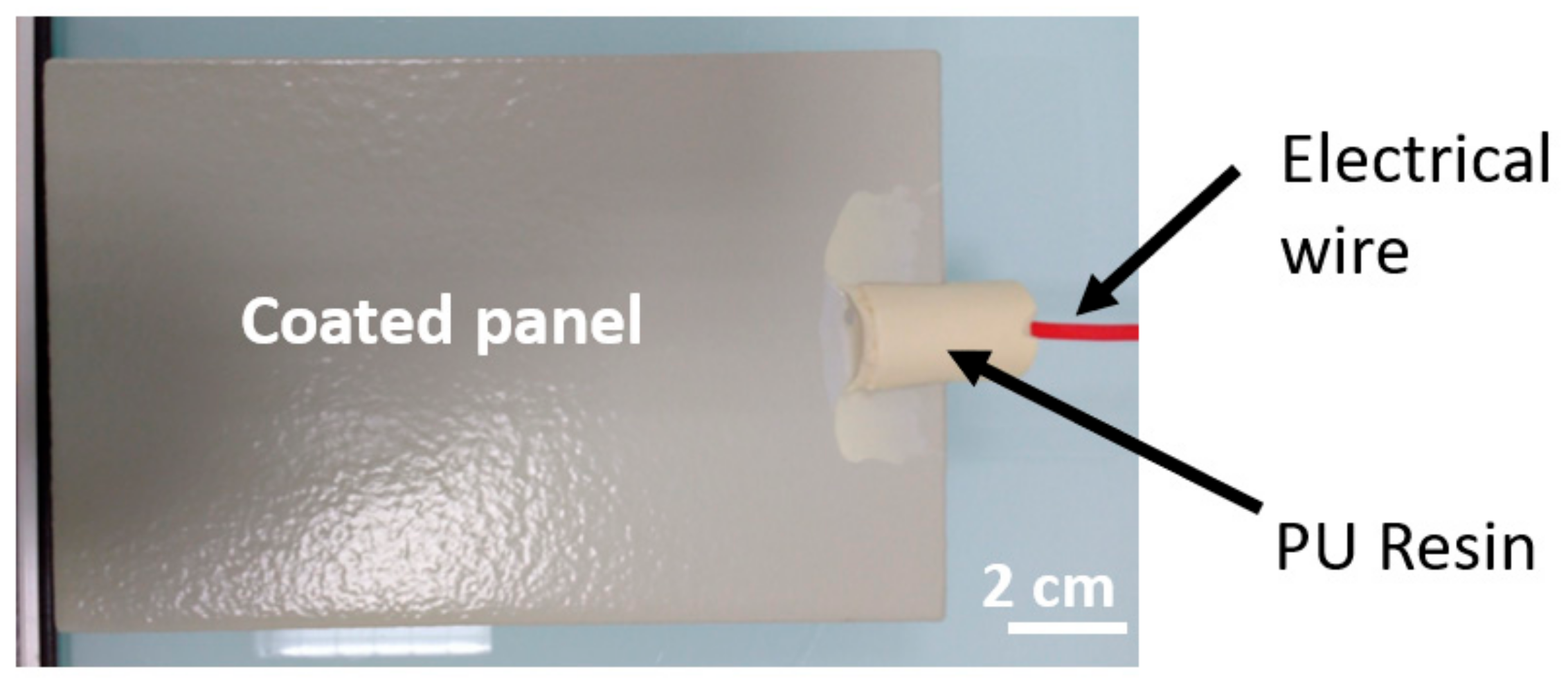
Figure 1. Coated panel with electrical connection.
Cmd 02 00039 g001
Figure 2. X-cut panel.
Cmd 02 00039 g002
Figure 3. Typical EIS raw data obtained for panel ROX5 (a) impedance modulus |Z| in ohm (Ω) and (b) the phase Theta in degree (°).
Cmd 02 00039 g003aCmd 02 00039 g003b
Figure 4. Evolution of the reduced impedance modulus |Z|0.1 Hz/e vs. ageing time for ROX system (a), RG system (c), and RM system (e) and evolution of the reduced impedance modulus |Z|0.1 Hz/e vs. reduced time for ROX system (b), RG system (d), and RM system (f) during the immersion at 35 °C in laboratory.
Cmd 02 00039 g004aCmd 02 00039 g004bCmd 02 00039 g004c
Figure 5. Evolution of the volume water uptake values with reduced time for (a) ROX system, (b) RG system, and (c) RM system during the immersion at 35 °C in laboratory.
Cmd 02 00039 g005aCmd 02 00039 g005b
Figure 6. Evolution of |Z|0.1 Hz/e vs. reduced time for the ageing in natural seawater for (a) ROX system, (b) RG system, and (c) RM system.
Cmd 02 00039 g006
Figure 7. Evolution of |Z|0.1 Hz/e vs. reduced time for the ageing in cyclic NSS for (a) ROX system, (b) RG system, and (c) RM system.
Cmd 02 00039 g007aCmd 02 00039 g007b
Figure 8. Evolution of |Z|0.1 Hz/e vs. reduced time for the ageing in alternate cycling for (a) ROX system, (b) RG system, and (c) RM system.
Cmd 02 00039 g008aCmd 02 00039 g008b
Figure 9. Evolution of the corrosion degree for X-cut panels immersed in NaCl solution at 35 °C.
Cmd 02 00039 g009
Figure 10. Evolution of the corrosion degree for X-cut panels submitted to cyclic NSS.
Cmd 02 00039 g010
Figure 11. Evolution of the corrosion degree for X-cut panels submitted to alternate cycling.
Cmd 02 00039 g011
Table 1. Name of the systems, composition of the systems, and total dry film thicknesses of the studied organic coating systems.
System NamePaint SystemTotal Dry Film Thickness
Organic system
ROX
Hempadur 45703: 250 µm + Hempadur 45753: 250 µm500 µm
Galvanized system
RG
Hempadur 15570: 50 µm + Hempadur 45703: 200 µm + Hempadur 45753: 250 µm500 µm
Thermal spray system
RM
Hempadur 45703: 30 µm + Hempadur 45703: 250 µm + Hempadur 45753: 250 µm530 µm
Table 2. Name and measured thickness of the defect-free coated panels tested in the different ageing conditions.
Ageing ConditionsPanel NameThickness
(µm)
Panel NameThickness
(µm)
Panel NameThickness
(µm)
Immersion at 35 °C in NaCl solutionROX1544RG1555RM1630
ROX2658RG2514RM2634
ROX3618RG3528RM3577
ROX4535RG4479RM4615
ROX5578RG5539RM5612
ROX6683RG6505RM6650
Immersion in seawaterROX1_nat490RG1_nat490RM1_nat594
ROX2_nat542RG2_nat542RM2_nat569
ROX3_nat524RG3_nat524RM3_nat599
ROX4_nat584RG4_nat584RM4_nat653
ROX5_nat514RG5_nat514RM5_nat640
ROX6_nat554RG6_nat554RM6_nat541
Cyclic NSSROX1_NSS651RG1_NSS725RM1_NSS667
ROX2_NSS521RG2_NSS536RM2_NSS679
ROX3_NSS483RG3_NSS719RM3_NSS696
ROX4_NSS517RG4_NSS711RM4_NSS669
Alternate cyclingROX1_AC594RG1_AC720RM1_AC756
ROX2_AC571RG2_AC705RM2_AC741
ROX3_AC600RG3_AC648RM3_AC690
ROX4_AC530RG4_AC671RM4_AC708
ROX5_AC594RG5_AC662RM5_AC796
ROX6_AC640RG6_AC681RM6_AC708
Publisher’s Note: MDPI stays neutral with regard to jurisdictional claims in published maps and institutional affiliations.