Article

Self-Healing Coatings Consisting of an Outer Electrodeposited Epoxy Resin Layer and an Inner Porous Anodic Oxide Layer with Healing Agents for the Corrosion Protection of Al Alloys

National Institute of Technology, Asahikawa College, Asahikawa 071-8142, Japan
*
Author to whom correspondence should be addressed.
Corros. Mater. Degrad. 2023, 4(3), 516-527; https://doi.org/10.3390/cmd4030027
Submission received: 2 July 2023 / Revised: 5 September 2023 / Accepted: 14 September 2023 / Published: 18 September 2023

Abstract

:
Recently, new surface treatments for the corrosion protection of Al alloys by forming self-healing layers have attracted the attention of many researchers. The authors of this paper have previously developed self-healing polyurethane coatings with micro-capsules containing healing agents and porous anodic oxide films filled with healing agents. In this study, self-healing coatings consisting of an outer electrodeposited epoxy resin layer and an inner porous anodic oxide layer with healing agents were developed for the corrosion protection of Al alloys. The corrosion protection abilities of the self-healing coating were shown in Cu2+/Cl solutions after damaging with indenters and were affected by freezing treatments and the tip angles of the indenter.

1. Introduction

Galvanized steels have domestically been commonly used as automobile body components [1,2,3], and they are going to be replaced with Al alloys because they have low densities, low costs, and excellent processabilities [4,5,6]. The corrosion protection abilities of Al alloys are too low for them to be used as industrial products for long-term applications because the corrosion of Al alloy products causes the deterioration of their performances and safeties. Therefore, surface treatments, including anodizing, chemical treatments, organic coating, metal plating, and thermal spraying, are applied to improve the corrosion protection of Al alloy products [7,8,9,10].
However, when the films formed by the surface treatment are damaged physically and the substrate is exposed to the surroundings, the local corrosion of Al soon occurs [11,12,13,14,15]. From this viewpoint, “self-healing coatings” that are automatically healed without maintenance have attracted a lot of attention from many researchers.
Firstly, a self-healing coating was proposed by S. R. White et al. [16]. Capsules containing dicyclopentadiene, as a liquid repairing solution, and a catalyst for the promotion of the repairing of the coating were dispersed in a coating. When cracking of the coating occurs due to physical damage, the cracking breaks the capsules. The repairing solution flows from the capsules into the cracks and fills the cracks by capillary action. Then, the repairing solution reacts with the catalyst to form a structure with a cross-linked network at the damaged area of the coating.
Lingwei Ma et al. [17] successfully produced a novel core–shell nano-container consisting of a core of TiN nanoparticles and a shell of mesoporous silica. The core–shell nano-container was incorporated into a thermo-responsive shape memory polymer (SMP) mixed with an epoxy coating to provide ultra-fast self-healing properties and corrosion protection. SiO2 core–shell nano-containers also served as a reservoir for benzotriazole (BTA)-based corrosion inhibitors. The BTA-based corrosion inhibitor was efficiently released by the photothermal effect. The heat generated by the photothermal effect of the TiN core induced the shape memory effect of the coating matrix, and this induced the damage closure effect.
The authors of this study recently developed self-healing polyurethane coatings with micro-capsules containing healing agents. The healing mechanism is similar to that described above [18,19]. In this case, the capsules consist of a polyurethane shell and a diisocyanate core [20,21]. When the capsules are broken, the diisocyanate flows into the damaged area and reacts with moisture in the air to form a polyurethane-like polymer Equation (1). Finally, the polymer covers the substrate exposed by the damage to the coating.
OCN-R-NCO + H2O → H2N-R-NH2 + CO2
Healing Agent
(Diisocyanate)

OCN-R-NCO + H2N-R-NH2 → -CONH-R-NH-
However, the synthesis of the capsule includes relatively complex processes and gives low yields of capsules. In order to solve this problem, the authors developed a new type of self-healing coating [22,23]. In the new process, Al alloys are anodized in oxalic acid solutions to form porous anodic oxide films [24,25,26,27,28,29,30], and the pores of the anodic oxide film are filled with healing agents. Then, a polyurethane coating is spread on the specimen (Figure 1a). When the specimen is damaged, the porous oxide film is broken simultaneously, and the healing agent filling the pores flows into the damaged area (Figure 1b). By reacting the healing agents with moisture in the air, a self-healing structure is formed on the exposed substrate (Figure 1c).
When Al alloys are used as automobile body components, a typical surface treatment that is applied to the components includes electrodeposition. Thus, developments in electrodeposited coatings with self-healing properties for the corrosion protection of Al alloys is significantly important for industrial purposes. However, it is unclear whether the technique of the formation of a self-healing polyurethane coating can be applied to that of the electrodeposition of an epoxy coating. In order to keep the corrosion protection abilities high after damage to the coating occurs, the self-healing structure formed at the damaged areas must firmly adhere to the coating. The self-healing structure consisting of a polyurethane-like polymer firmly adheres to the polyurethane coating, but it may not adhere to the electrodeposited epoxy resin coating.
In cold regions where the outdoor temperature drops to lower than 0 °C in winter, rain freezes on the body of automobiles, and the ice may cause physical damage to the body, especially at the healed areas due to volume expansion through phase transformation.
In the present study, the effects of the tip angle of indenters and freezing treatments on the self-healing properties for the corrosion protection of Al alloys covered with electrodeposited epoxy resin coatings on porous anodic oxide films filled with healing agents are examined by electrochemical impedance spectroscopy (EIS) and scanning electron microscopy (SEM).

2. Materials and Methods

2.1. Formation of Self-Healing Electrodeposition Coating

Specimens of 1050 Al alloy plates (Fe: 0.25, Si: 0.15, Cu: 0.05, Al: 99.5 mass%) with a 1.5 mm thickness were cut into 20 × 20 mm specimens. The specimens were electropolished in a 78 vol% CH3COOH/22 vol% HClO4 solution with a constant voltage of 30 V for 30 s as a pretreatment. Then, the pretreated specimens were anodically oxidized in a 2 wt% (COOH)2 solution with a constant current density of 200 A m−2 at 313 K for 60 min to form porous oxide films with a thickness of 30 μm on the specimens.
After anodizing, the specimens were immersed in isophorone diisocyanate (IPDI), a coating-healing agent, for 100 min under supersonic vibration to fill the pores with this agent. On the surface of the specimens, a prepolymer mixture of polyurethane and ethylene glycol at a mass ratio of 75:10 was spread to form a thin polyurethane coating, covering the healing agent in the pores of the porous films. Then, all the specimens were aged for 48 h in an air atmosphere at room temperature.
The prepolymer was produced by the following procedure. First, 2,4-tolylene-diisocyanate (TDI) was reacted with glycerol at a mass ratio of 1:6 in cyclohexanone at 348 K for 24 h under agitation at 600 rpm. In order to remove water from this solution, N2 gas was blown into the solution during the first 1 h.
Finally, electrophoretic deposition was carried out in a cationic electrodeposition coating solution (NIPPON PAINT AUTOMOTIVE COATINGS CO., LTD., Hirakata, Japan), which is used as a primer coating for automobile bodies, at a constant potential of −20 V for 60 min to obtain an epoxy resin coating with a thickness of 30 μm on the specimens after filling the pores with healing agents, and then aging was carried out for 24 h in an air atmosphere at room temperature.

2.2. Scratching of Coating Films with Indenters and Freezing Treatments

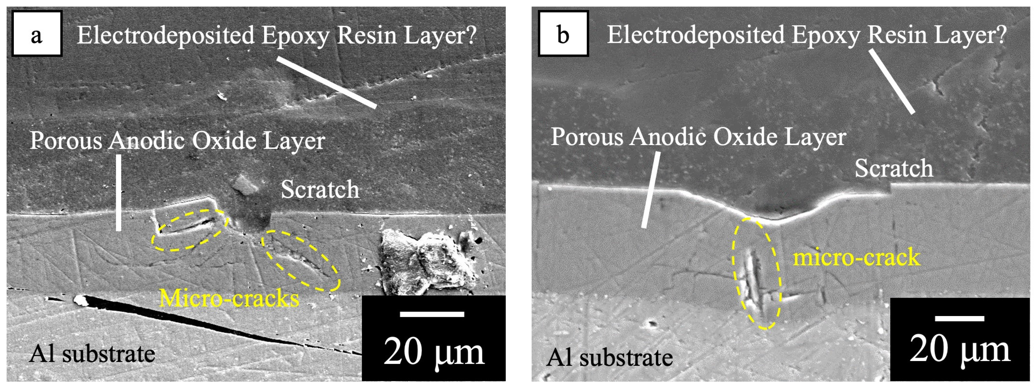
In order to evaluate the self-healing properties of the electrodeposited coatings, 5 lines of scratches were formed on the specimens with the coated layer using two types of indenters. One was a cutter-type indenter with a tip angle of 50°, and the other was a conical-type one with a tip angle of 120°. The depth of the scratches was adjusted to about 45 μm by controlling the load (see Figure A1).
After aging for 24 h, 0.16 mL of Milli-Q water was dropped onto the scratched surface, and the specimens were kept at −25 °C for 5 h and then kept at 20 °C for 3 h. The time transients from room temperature to −25 °C and from −25 °C to 20 °C were one hour. During the freezing treatment, water on the specimens was present in a liquid phase for about 3 h and in a solid phase for about 5 h. The surface of specimens before/after the freezing treatments was observed by SEM.

2.3. Evaluation of Corrosion Protection of Damaged Specimens with Self-Healing Coating

In order to examine the corrosion protection of the specimens with the coating, cross-shaped scratches were formed on the specimen surfaces by two types of indenters with 50° and 120° tip angles, and then the specimens were immersed in a 1.57 × 10⁻³ M-CuSO4/0.57 M KCl solution for 24 h at room temperature. After the corrosion tests, the specimens were immersed in a commercially available coating remover (Shimizu Corporation: Non-Chrome W) at 75 °C for 1–2 h to remove the electrodeposited coating and then immersed in a 10 wt% H3PO4/4 wt% K2CrO4 solution for 40 min at 363 K to remove deposited Cu particles, corrosion products, anodic oxide films, and healing agents. The surface morphology of the specimens after the corrosion test and after immersion in the coating remover and the H3PO4/K2CrO4 solution was observed by SEM. In the present study, 4 specimens were prepared for each condition in order to examine the reproducibility of the SEM images. There was no significant difference among the samples under each condition. The SEM images shown here are typical ones.
The corrosion protection of the damaged specimens with the self-healing coating was also evaluated by EIS in a boric/borate buffer solution (pH 8.4) after bubbling N2 gas for 20 min. Pt mesh and Ag/AgCl/saturated KCl electrodes were used as the counter and reference electrodes, respectively. A potential amplitude ranging from 50 mV to a rest potential of −550 mV (vs. R.E.) was applied in the frequency range between 1 × 10⁻¹ and 1 × 10⁵ Hz. The value of −550 mV (vs. R. E.) was the rest potential of the electropolished specimen. Here, 7 samples were prepared for the EIS measurements.

3. Results

3.1. Healing Behavior of Self-Healing Coatings after Damaging with 50° and 120° Tip Angle Indenters

Figure 2 shows the SEM images of the surface of the specimens covered with films consisting of: (a) an outer electrodeposited epoxy resin layer and an inner porous anodic oxide layer (normal coating), (b) films consisting of an outer electrodeposited epoxy resin layer and an inner anodic oxide layer filled with healing agents (self-healing coating), and (c) the self-healing coating after the freezing treatments (self-healing coating with freezing). All the photos were taken at the areas damaged by scratching with a 50° tip angle indenter. In Figure 2a–c, cracks can be seen with a width of 20–25 μm, as shown by the dotted lines in the image. The rough patterns outside the cracks may have been due to the detachment of the outer epoxy resin layer from the inner anodic oxide layer. As shown in Figure 2b,c, as well as in Figure 2a, it seems that there was no healing structure in the cracks.
Figure 3 shows the SEM images of the surface of the specimens after scratching with a 120° tip angle indenter covered with: (a) the normal coating, (b) the self-healing coating, and (c) the self-healing coating with freezing. As shown in Figure 3a–c, clear and wide cracks can be seen at the center of the images on all the specimens. The difference in the crack widths in Figure 3a–c cannot be explained clearly, but they may have been due to the effect of the healing structure or the freezing treatments. There was no self-healing structure in the samples shown in Figure 3b,c. This agrees with that shown in Figure 2a–c and is discussed in Section 4.1.

3.2. Corrosion Behavior of Self-Healing Coating during Immersion in Cu2+/Cl Solution after Scratching with 50° Tip Angle Indenter

In previous studies, the authors of this paper found that a Cu2+/Cl solution is significantly useful for detecting imperfections in oxide films on Al alloys [18,19,22,23]. Cu2+ and Cl ions synergistically enhance the local corrosion of Al alloys through imperfections. Copper particles are deposited on the specimens through the imperfections in the oxide film by the reaction indicated in Equation (2).
2Al + 3Cu2+ → 2Al3+ + 3Cu
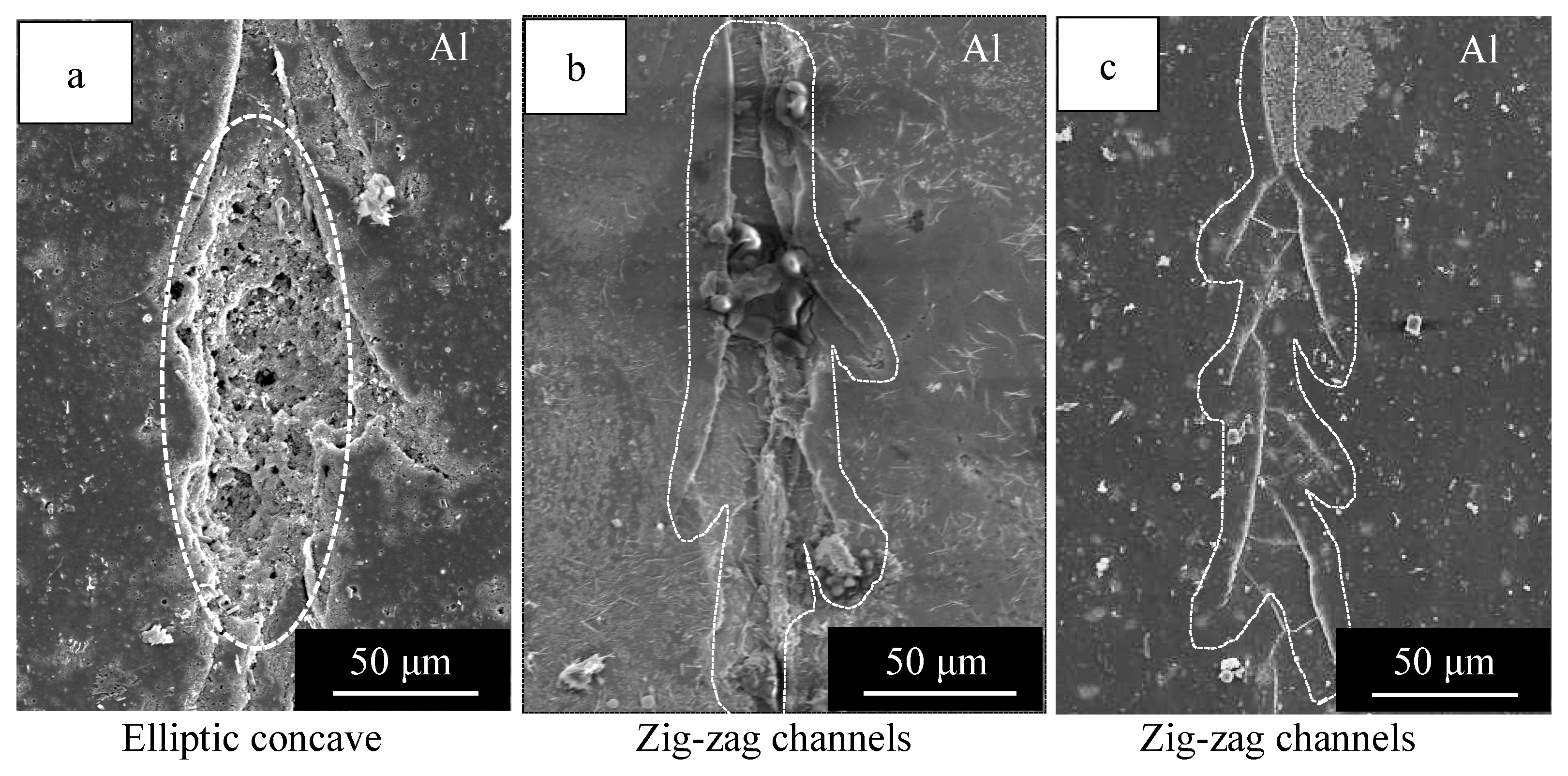
Figure 4 shows the SEM images of the surface of specimens covered with: (a) normal coating, (b) the self-healing coating, and (c) the self-healing coating with freezing after the corrosion tests in a Cu2+/Cl solution and after the removal of the coatings, oxide films, healing agents, corrosion products, and deposited Cu particles. All the photos were taken at areas scratched with a 50° tip angle indenter. In Figure 4a, an elliptical concave section with an area of 100 × 50 μm2 and several deep pits with a diameter of about 5 μm can be seen. Further, zig-zagging narrow channels in the vertical direction of the image can be seen along the scratch. In Figure 4b,c, zig-zagging narrow channels can be seen, but there are no elliptical concave areas or deep pits. The patterns in Figure 4 reflect the corrosion of the substrate. The elliptical concave section with an area of 100 × 50 μm2 represents relatively severe corrosion and the deep pits correspond to pitting corrosion. The zig-zagging channels are considered to correspond to slight corrosion through micro-cracks formed in the innermost oxide layer by the scratching. This is discussed in Section 4.1.
It can be seen from Figure 4 that the specimen covered with the normal coating proceeded much more severely than that covered with the self-healing coating and that the freezing treatments only slightly affected the corrosion rate.
Figure 5 shows the Bode plot from the EIS measurements obtained for the speci-mens covered with the normal coating (Cmd 04 00027 i001), self-healing coating (Cmd 04 00027 i002), and self-healing coating with freezing (Cmd 04 00027 i003). All the curves were measured after scratching with a 50° tip angle indenter.
As can be seen in this figure, the plot of log Z vs. log f for the self-healing coating (Cmd 04 00027 i002) and the self-healing coating with freezing (Cmd 04 00027 i003) had a linear relationship with a slope of −1 between 10 and 104 Hz, and the Z values for the self-healing coating were the same as those for the self-healing coating with freezing between 10 and 104 Hz. The plot of log Z vs. log f for the normal coating (Cmd 04 00027 i001) had a flatter slope than −1, and the Z values were much smaller than those of the self-healing coatings with/without freezing. The Δθ values on the three kinds of specimens decreased with increasing f and then increased with increasing f, passing through a minimum. The minimum values of Δθ were almost −90° for the self-healing coatings with/without freezing and −60° for the normal coating. The data for the self-healing coating (Cmd 04 00027 i002) and the self-healing coating with freezing (Cmd 04 00027 i003) showed an appreciable scattering between 0.1 and 1 Hz, and this was due to high impedances.

3.3. Corrosion Behavior of Self-Healing Coating Film after Damaging with 120° Tip Angle Indenter

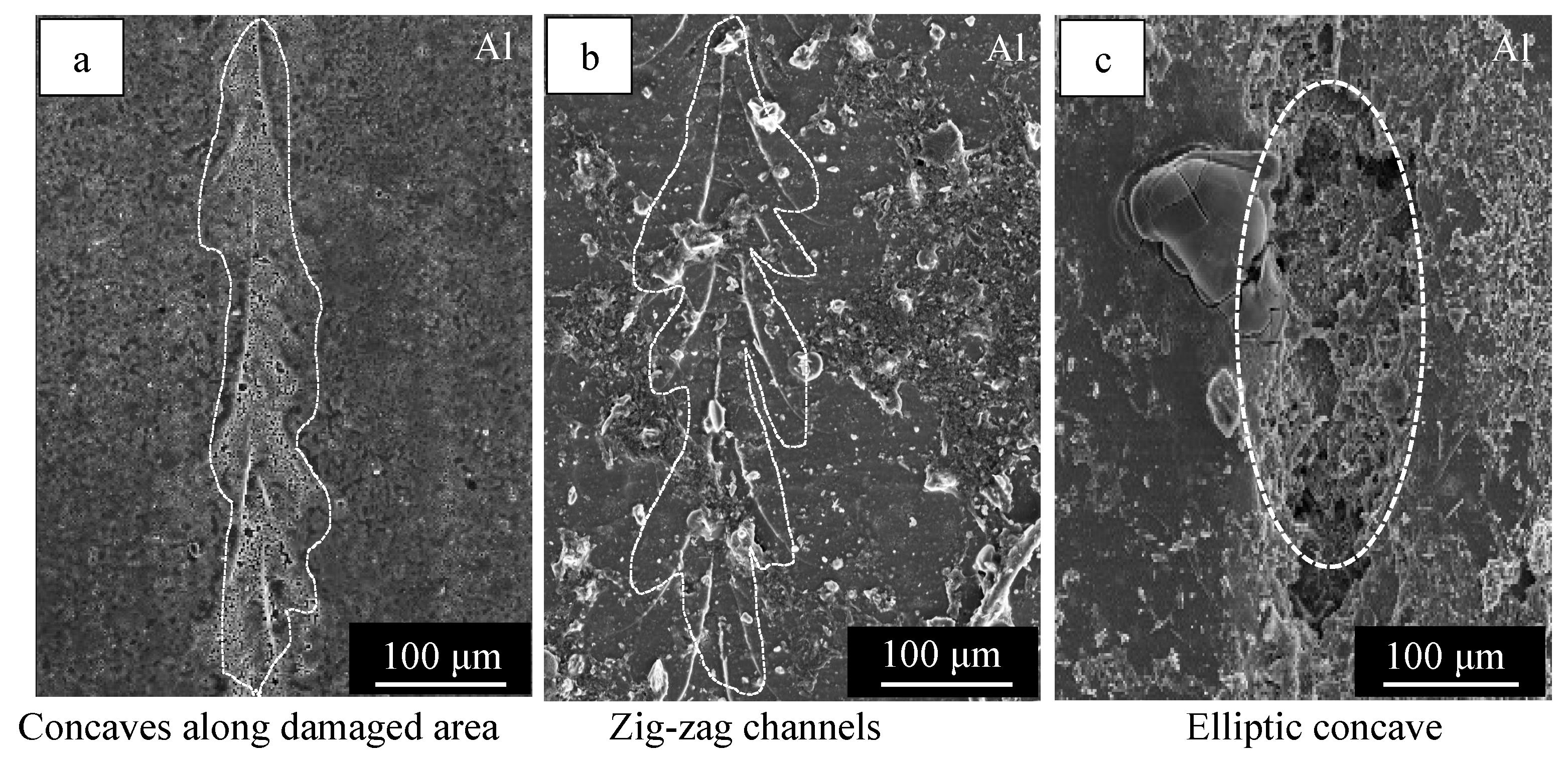
Figure 6 shows the SEM images of the surface of the specimens with: (a) the normal coating, (b) the self-healing coating, and (c) the self-healing coating with freezing, obtained after damaging with a 120° tip angle indenter, corrosion tests, and the removal of the coating, oxide film, healing agents, corrosion products, and deposited Cu particles.
In Figure 6a, it can be seen that there were shallow concaves along the damaged area and pits as small as 10 µm in size, suggesting that local corrosion proceeded at the damaged areas. In Figure 6b, it can be seen that a zig-zagging linear pattern appeared along the damaged area. In Figure 6c, it can be seen that there was an elliptical concave area that was 300 × 100 μm in size and pits with a 10 μm diameter. It is clear from Figure 6 that the corrosion protection ability of the specimens covered with the self-healing coating was the highest after damaging with a 120° tip angle indenter and that the freezing treatments significantly suppressed the corrosion protection ability of the specimens covered with the self-healing coating, leading to a lower ability than that of the specimen with the normal coating. This was entirely different from the results obtained with the 50° tip angle indenter (see Figure 5), and the difference in the behavior between the 50° and 120° tip angle indenters is discussed in Section 4.1 and Section 4.2.
Figure 7 shows Bode plot obtained from the EIS measurements for the specimens covered with the normal coating (Cmd 04 00027 i001), self-healing coating, (Cmd 04 00027 i002) and self-healing coating with freezing (Cmd 04 00027 i003) after damaging with a 120° tip angle indenter. As can be seen in this figure, the plot of log Z vs. log f for all the specimens had a linear relationship between 10 and 1000 Hz. The relationship for the specimen covered with the self-healing coating had a slope of almost −1, but the relationships for the specimens covered with the normal coating and self-healing coating with freezing had slopes less than −1. The Z values between 10 and 1000 Hz for the three kinds of specimens were in the following order:
Self-healing coating >> Normal coating > Self-healing coating with freezing
The Δθ values of all the specimens decreased with increasing f and then increased with increasing f, passing through a minimum between 10−1 and 104 Hz. The minimum value was in the following order:
Normal coating = Self-healing coating with freezing >> Self-healing coating
Comparing Figure 5 with Figure 7, one can see that impedance of the self-healing coating with freezing (Cmd 04 00027 i003) was considerably decreased after damaging it with a 120° tip angle indenter, while it remained constant after damaging it with a 50° tip angle indenter.

4. Discussion

4.1. Analysis of the EIS Data of the Specimens Covered with Normal Coating and Self-Healing Coating after Damaging

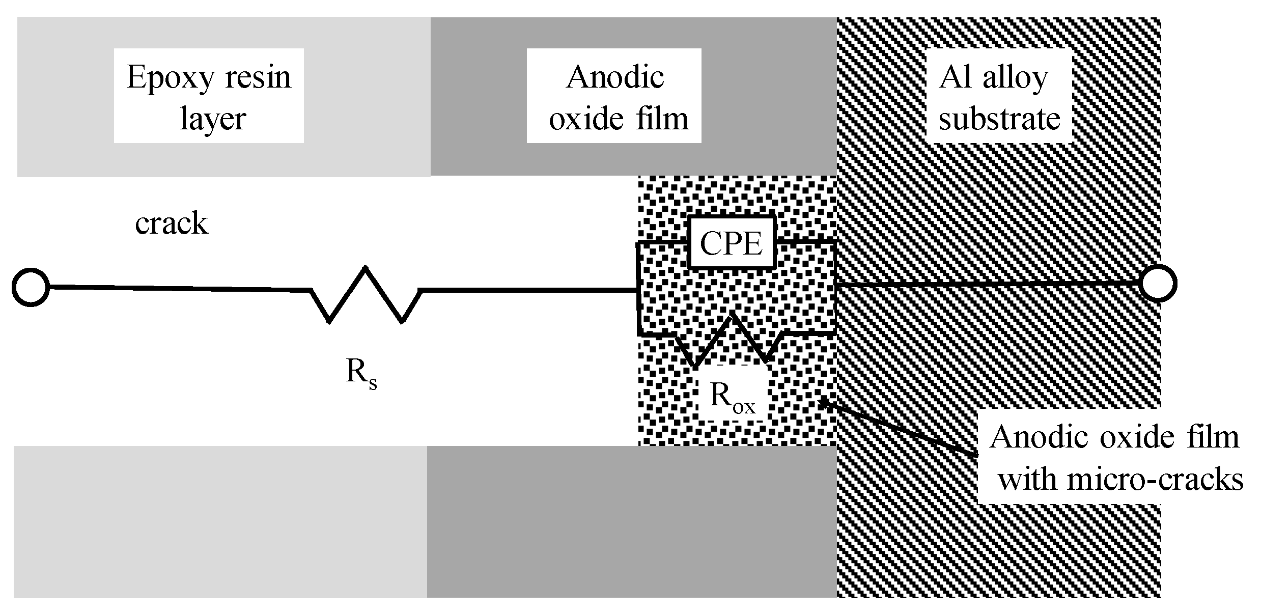
From the EIS data shown in Figure 5 and Figure 7, an equivalent circuit can be assumed, as shown in Figure 8 [22,31,32,33,34].
The equivalent circuit is presented by a series connection between Rs, the solution resistance in the crack formed by scratching, and CPE, the constant phase element of the anodic oxide films remaining unremoved at scratched area, which has a parallel connection with Rox, the resistance of the anodic oxide film at the scratched area. The corrosion protection ability of the coating at the damaged area can be evaluated from the value of Rox in the equivalent circuit. The Rox values of the specimens covered with the normal coating, self-healing coating, and self-healing coating with freezing are summarized in Figure 9. The Rox value of the three kinds of specimens was in the following order:
Self-healing coating > Self-healing coating with freezing >> Normal coating
It is clear that self-healing coating had a high corrosion protection ability after being damaged and that the freezing treatment slightly suppressed the corrosion protection ability.

4.2. Effects of Freezing Treatments and the Tip Angle of Indenters on Corrosion Protection of the Self-Healing Coating

When the specimens covered with the normal coating, which had an outer epoxy resin layer with a thickness of 30 μm and an inner anodic oxide layer with a thickness of 30 μm, were damaged with indenters, cracks with a depth of 45 μm were formed under the conditions used in the present study, indicating that the innermost layer of the anodic oxide layer remained unremoved with a thickness of 15 μm. The unremoved innermost oxide layer can be considered to have a network of micro-cracks due to stresses during the scratching with indenters. During the corrosion tests, the Cu2+/Cl solution penetrated through the micro-cracks, leading to a relatively severe level of corrosion on the substrate (see Figure 4a and Figure 6a).
When the self-healing coatings were scratched with indenters, the healing agents flowed into the damaged area and penetrated through the micro-cracks, leading to the appreciable suppression of the corrosion of the substrate. This is also demonstrated in Figure 4b and Figure 6b. The amount of the healing agents flowing into the damaged area was too small to form a self-healing structure in the crack, as shown in Figure 1.
The effect of the angle of the tips of the indenters on the formation of micro-cracks can be explained as follows. By scratching with the indenters, triangular prism-shaped cracks were formed, and the whole thickness of the epoxy resin layer and half of the thickness of the anodic oxide layer were removed as debris. In addition, the organic coating and the anodic oxide layers next to the triangular prism-shaped cracks are considered to be subjected to compressive stresses in the direction perpendicular to the scratch line. Thus, the anodic oxide film underneath the bottom of the crack was subjected to tensile stresses, producing a network of micro-cracks there.
The indenter with a 120° tip angle produced more obtuse cracks than that with a 50° tip angle. Thus, the stress to the oxide film underneath the crack was larger with the 120° tip angle indenter than with the 50° tip angle indenter, and a larger network of micro-cracks could develop. This was clarified by the fact that the corrosion after damaging proceeded more significantly with the 120° tip angle indenter than with the 50° tip angle indenter, as shown in Figure 4b and Figure 6b.
The effect of the freezing treatments on the structure of network of micro-cracks is discussed below. When 0.16 mL of water was dropped on the specimens covered with the self-healing coating after scratching with indenters, the cracks were filled with water, and the water penetrated through the micro-cracks in the innermost layer, remaining unremoved. By dropping the temperature of the specimens from room temperature to −25 °C, the volume of water expanded by about 10% due to phase transformation. The outer epoxy resin layer tended to be deformed elastically and plastically so that the crack became larger during the temperature drop. When the specimens were heated from −25 °C to 20 °C, the crack volume shrank slightly. The polyurethane-like polymer in the micro-cracks may show a similar behavior to the epoxy resin coating.
During the temperature drop, the anodic oxide film tended to be deformed elastically and to break beyond the yield point. The difference in the deformation type between the organic substances and the anodic oxide films can be considered to cause a gap between them in the micro-cracks, leading to the enhancement of the corrosion of the substrate during immersion in the Cu2+/Cl solution. This was ascertained by the facts shown in Figure 4c and Figure 6c.
Consequently, the enhancement of the corrosion by scratching with the 120° tip angle indenter and the freezing treatment was a result of the synergistic effects of the extent of the transfer of the Cu2+/Cl solution by the two treatments.

5. Conclusions

In the present study, a self-healing coating, which consisted of an outer electrodeposited epoxy resin layer and an inner anodic oxide layer with healing agents, was developed, and the effects of the tip angles of indenters scratching the coating and freezing treatments on the self-healing ability of the coating for the corrosion protection of Al alloys were examined. The following conclusions were drawn:
1. Self-healing coatings consisting of an outer electrodeposited epoxy resin layer and an inner anodic oxide layer with self-healing agents can be successfully obtained, and the corrosion protection abilities of the coating were kept high after scratching with indenters.
2. The corrosion protection abilities of the specimens covered with the self-healing coating suffered significantly from an indenter with an obtuse-angled tip and from a freezing treatment.

Author Contributions

Conceptualization, M.C.; Investigation, R.T. and K.H.; Writing—original draft, R.T.; writing—review and editing, H.T. and M.C.; Project administration, M.C. All authors have read and agreed to the published version of the manuscript.

Funding

This study was supported by Kato Foundation for Promotion of Science.

Data Availability Statement

The data is available on reasonable request from the corresponding author.

Conflicts of Interest

The authors declare no conflict of interest.

Appendix A

Figure A1. Cross-sectional images of specimens with normal coating after damaging with 50° (a) and 120° (b) tip angle indenters. These images were taken after embedding the specimen in epoxy resin. In these images, the interface between electrodeposited coating and embedded resin is not clear because of the similarity in the chemical compositions of these organic compounds.
Cmd 04 00027 g0a1

References

  1. Vural, M.; Akkus, A. On the resistance spot weldability of galvanized interstitial free steel sheets with austenitic stainless steel sheets. J. Mater. Process. Technol. 2004, 153–154, 1–6. [Google Scholar] [CrossRef]
  2. Fujita, S.; Mizuno, D. Corrosion and corrosion test methods of zinc coated steel sheets on automobiles. Corros. Sci. 2007, 49, 211–219. [Google Scholar] [CrossRef]
  3. Mei, L.; Chen, G.; Jin, X.; Zhang, Y.; Wu, Q. Research on laser welding of high-strength galvanized automobile steel sheets. Opt. Lasers Eng. 2009, 47, 1117–1124. [Google Scholar] [CrossRef]
  4. Miller, W.S.; Zhuang, L.; Bottema, J.; Wittebrood, A.J.; De Smet, P.; Haszler, A.; Vieregge, A. Recent development in aluminium alloys for the automotive industry. Mater. Sci. Eng. 2000, 280, 37–49. [Google Scholar] [CrossRef]
  5. Lee, S.H.; Saito, Y.; Sakai, T.; Utsunomiya, H. Microstructures and mechanical properties of 6061 aluminum alloy processed by accumulative roll-bonding. Mater. Sci. Eng. 2002, 325, 228–235. [Google Scholar] [CrossRef]
  6. Ozturk, F.; Sisman, A.; Toros, S.; Kilic, S.; Picu, R.C. Influence of aging treatment on mechanical properties of 6061 aluminum alloy. Mater. Des. 2010, 31, 972–975. [Google Scholar] [CrossRef]
  7. Martínez-Viademonte, M.P.; Abrahami, S.T.; Hack, T.; Burchardt, M.; Terryn, H. A Review on Anodizing of Aerospace Aluminum Alloys for Corrosion Protection. Coating 2020, 10, 1106. [Google Scholar] [CrossRef]
  8. Yanagimoto, H.; Saito, K.; Okuyama, H.; Takahashi, H.; Chiba, M. Changes in the structure and corrosion protection ability of porous anodic oxide films on pure Al and Al alloys by pore sealing treatment. Materials 2022, 15, 8544. [Google Scholar] [CrossRef] [PubMed]
  9. Atz-Dick, P.; Konrath, A.; Melo, Y.R.; Ratke, C.; Dick, L.F.P. Aluminum anodizing with simultaneous silanization for increased hydrophobicity and corrosion protection. Appl. Surf. Sci. 2022, 593, 153392. [Google Scholar] [CrossRef]
  10. Titu, A.M.; Sandor, R.-N.; Pop, A.B. Research on the Influence of Coating Technologies on Adhesion Anti-Corrosion Layers in the Case of Al7175 Aluminum Alloy. Coatings 2023, 13, 1054. [Google Scholar] [CrossRef]
  11. Dehri, I.; Erbil, M. The effect of relative humidity on the atmospheric corrosion of defective organic coating materials: An EIS study with a new approach. Corros. Sci. 2000, 42, 969–978. [Google Scholar] [CrossRef]
  12. Khramov, A.N.; Voevodin, N.N.; Balbyshev, V.N.; Donley, M.S. Hybrid organo-ceramic corrosion protection coatings with encapsulated organic corrosion inhibitors. Thin Solid Films 2004, 447–448, 549–557. [Google Scholar] [CrossRef]
  13. Zhong, C.; Tang, X.; Cheng, Y.F. Corrosion of steel under the defected coating studied by localized electrochemical impedance spectroscopy. Electrochim. Acta 2008, 53, 4740–4747. [Google Scholar] [CrossRef]
  14. Dong, C.F.; Fu, A.Q.; Li, X.G.; Cheng, Y.F. Localized EIS characterization of corrosion of steel at coating defect under cathodic protection. Electrochim. Acta 2008, 54, 628–633. [Google Scholar] [CrossRef]
  15. Tavandashti, N.P.; Ghorbani, M.; Shojaei, A.; Mol, J.M.C.; Terryn, H.; Baert, K.; Gonzalez-Garcia, Y. Inhibitor-loaded conducting polymer capsules for active corrosion protection of coating defects. Corros. Sci. 2016, 112, 138–149. [Google Scholar] [CrossRef]
  16. White, S.R.; Sottos, N.R.; Geubelle, P.H.; Moore, J.S.; Kessler, M.R.; Sriram, S.R.; Brown, E.N.; Viswanathan, S. Autonomic healing of polymer composites. Nature 2001, 409, 794–797. [Google Scholar] [CrossRef] [PubMed]
  17. Ma, L.; Wang, J.; Zhang, D.; Huang, Y.; Huang, L.; Wang, P.; Qian, H.; Lic, X.; Terryn, H.A.; Mol, J.M.C. Dual-action self-healing protective coatings with photothermal responsive corrosion inhibitor nanocontainers. Chem. Eng. J. 2021, 404, 127118. [Google Scholar] [CrossRef]
  18. Chiba, M.; Yamada, C.; Okuyama, H.; Sugiura, M.; Pletincx, S.; Verbruggen, H.; Hyono, A.; De Graeve, I.; Terryn, H.; Takahashi, H. Development of novel surface treatments for corrosion protection of aluminum: Self-repairing coatings. Corros. Rev. 2018, 36, 55–64. [Google Scholar] [CrossRef]
  19. Chiba, M.; Tsuji, Y.; Takada, R.; Eguchi, Y.; Takahashi, H. Formation of Self-Healing Organic Coatings for Corrosion Protection of Al Alloys by Dispersion of Spherical and Fibrous Capsules. Materials 2023, 16, 3018. [Google Scholar] [CrossRef] [PubMed]
  20. Yang, J.; Keller, M.W.; Moore, J.S.; White, S.R.; Sottos, N.R. Microencapsulation of Isocyanates for Self-Healing Polymers. Macromolecules 2008, 41, 9650–9655. [Google Scholar] [CrossRef]
  21. Sondari, D.; Septevani, A.A.; Randy, A.; Triwulandari, E. Polyurethane microcapsule with glycerol as the polyol component for encapsulated self healing agent. Int. J. Eng. Technol. 2010, 2, 466–471. [Google Scholar]
  22. Hirasawa, K.; Tomioka, Y.; Kawamura, M.; Hyono, A.; Chiba, M. Self-healing Coating by Using Pore of Porous Film Formed on Al Alloy Anodized and Effect of Pore-size on Self-healing Property of Coating. Zair.-Kankyo 2022, 71, 63–69. [Google Scholar] [CrossRef]
  23. Takada, R.; Hirasawa, K.; Chiba, M. Self-healing Coating by Using Pore of Porous Film Formed on Al Alloy Anodized and Effect of Pore-Widening Treatment on Corrosion Protection. Zair.-Kankyo 2022, 71, 300–307. [Google Scholar] [CrossRef]
  24. Tsangaraki-Kaplanoglou, I.; Theohari, S.; Dimogerontakis, T.; Wang, Y.-M.; Kuo, H.-H.; Kia, S. Effect of alloy types on the anodizing process of aluminum. Surf. Coat. Technol. 2006, 200, 2634–2641. [Google Scholar] [CrossRef]
  25. Zaraska, L.; Sulka, G.D.; Szeremeta, J.; Jaskuła, M. Porous anodic alumina formed by anodization of aluminum alloy (AA1050) and high purity aluminum. Electrochim. Acta 2010, 55, 4377–4386. [Google Scholar] [CrossRef]
  26. Oh, J.; Thompson, C.V. The role of electric field in pore formation during aluminum anodization. Electrochim. Acta 2011, 56, 4044–4051. [Google Scholar] [CrossRef]
  27. Runge, J.M. Anodizing for Design and Function. J. Mater. Sci. Nanotechnol. 2011, 1, 1. [Google Scholar]
  28. Roslyakov, I.V.; Gordeeva, E.O.; Napolskii, K.S. Role of Electrode Reaction Kinetics in Self-Ordering of Porous Anodic Alumina. Electrochim. Acta 2017, 241, 362–369. [Google Scholar] [CrossRef]
  29. Kikuchi, T.; Akiya, S.; Kunimoto, K.; Suzuki, R.O.; Natsui, S. Photoluminescence from Anodic Aluminum Oxide Formed via Etidronic Acid Anodizing and Enhancing the Intensity. Mater. Trans. 2020, 61, 1130–1137. [Google Scholar] [CrossRef]
  30. Buruberri, L.H.; Senff, L.; Seabra, M.P.; Labrincha, J.A. Effect of Al anodizing waste on the final properties of porous geopolymers. Constr. Build. Mater. 2020, 263, 120160. [Google Scholar] [CrossRef]
  31. Itagaki, M. Denkikagaku-Inpidansu-Ho, 2nd ed.; Maruzen-Shuppan: Tokyo, Japan, 2011; pp. 53–86. [Google Scholar]
  32. Xie, C.; Li, H.; Zhou, X.; Sun, C. Corrosion behavior of cold sprayed pure zinc coating on magnesium. Surf. Coat. Technol. 2019, 374, 797–806. [Google Scholar] [CrossRef]
  33. Liu, J.; Lu, Z.; Zhang, L.; Li, C.; Ding, R.; Zhao, X.; Zhang, P.; Wang, B.; Cui, H. Studies of corrosion behaviors of a carbon steel/copper-nickel alloy couple under epoxy coating with artificial defect in 3.5 wt.% NaCl solution using the WBE and EIS techniques. Prog. Org. Coat. 2020, 148, 105909. [Google Scholar] [CrossRef]
  34. Gaona-Tiburcio, C.; Montoya-Rangel, M.; Cabral-Miramontes, J.A.; Estupiñan-López, F.; Zambrano-Robledo, P.; Cruz, R.O.; Chacón-Nava, J.G.; Baltazar-Zamora, M.A.; Almeraya-Calderón, A. Corrosion Resistance of Multilayer Coatings Deposited by PVD on Inconel 718 Usin hemical Impedance Spectroscopy Technique. Coatings 2020, 10, 521. [Google Scholar] [CrossRef]
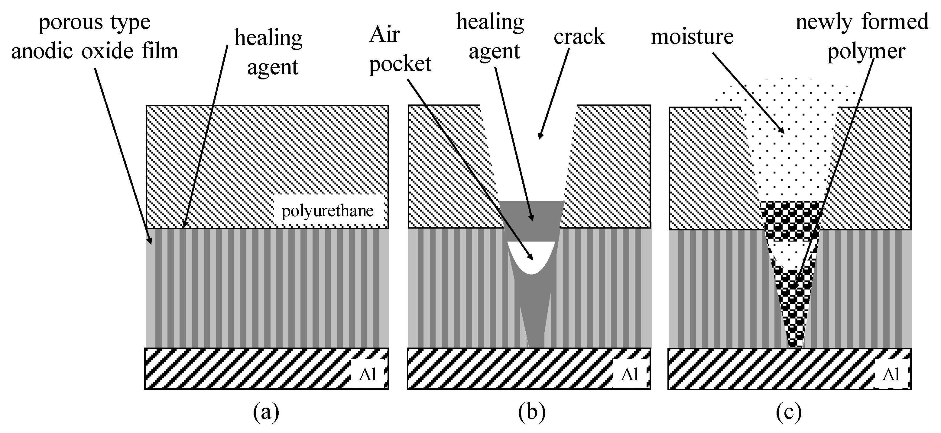
Figure 1. Schematic illustration of self-healing mechanism of coatings consisting of an outer polyurethane coating layer and an inner anodic oxide layer with healing agents. (a) Injection of healing agents into nano-pores of porous anodic oxide film and coating of outer polyurethane layer. (b) Flowing of healing agents into cracks at damaged areas. (c) Formation of self-healing structure to cover the exposed substrate.
Cmd 04 00027 g001
Figure 2. SEM images of the surface of specimens covered with: (a) films consisting of an outer electrodeposited epoxy resin layer and an inner porous anodic oxide layer (normal coating), (b) films consisting of an outer electrodeposited epoxy resin layer and an inner anodic oxide layer filled with healing agents (self-healing coating), and (c) the self-healing coating after freezing treatments (self-healing coating with freezing). All the photos were taken at areas damaged by scratching with 50° tip angle indenter.
Cmd 04 00027 g002
Figure 3. SEM images of the surface of specimens: (a) covered with normal coating, (b) covered with self-healing coating, and (c) covered with self-healing coating with freezing. All the photos were taken after scratching with 120° tip angle indenter.
Cmd 04 00027 g003
Figure 4. SEM images of the surface of specimens covered with: (a) normal coating, (b) self-healing coating, and (c) self-healing coating with freezing after the corrosion test in Cu2+/Cl solution and after removal of coating, oxide film, corrosion products, and deposited Cu particles. All the photos were taken at areas damaged with 50° tip angle indenters.
Cmd 04 00027 g004
Figure 5. Typical Bode plot from EIS measurements obtained for specimens covered with normal coating (Cmd 04 00027 i001), self-healing coating (Cmd 04 00027 i002), and self-healing coating with freezing (Cmd 04 00027 i003). All the curves were measured after scratching with 50° tip angle indenters.
Cmd 04 00027 g005
Figure 6. SEM images of the surface of specimens covered with: (a) normal coating, (b) self-healing coating, and (c) self-healing coating with freezing after the corrosion test in Cu2+/Cl solution and after removal of coating, oxide film, corrosion products, and deposited Cu particles. All the photos were taken at areas damaged with 120° tip angle indenters.
Cmd 04 00027 g006
Figure 7. Typical Bode plot from EIS measurements obtained for specimens covered with normal coating (Cmd 04 00027 i001), self-healing coating (Cmd 04 00027 i002), and self-healing coating with freezing (Cmd 04 00027 i003). All the curves were measured after scratching with 120° tip angle indenters.
Cmd 04 00027 g007
Figure 8. Equivalent circuit of coatings scratched with indenters. Rs: Solution resistance in the crack formed by scratching. CPE: Constant phase element of anodic oxide films remaining unremoved at scratched area. Rox: Resistance of the anodic oxide film at the scratched area.
Cmd 04 00027 g008
Figure 9. Average Rox value of seven specimens covered with: (N.C.) normal coating, (S.H.C.) self-healing coating, and (S.H.C.F.) self-healing coating with freezing.
Cmd 04 00027 g009
Disclaimer/Publisher’s Note: The statements, opinions and data contained in all publications are solely those of the individual author(s) and contributor(s) and not of MDPI and/or the editor(s). MDPI and/or the editor(s) disclaim responsibility for any injury to people or property resulting from any ideas, methods, instructions or products referred to in the content.