Article

The Formation of Small Amounts of Cyclopropane during Pulsed Pyrolysis of C4–C5 Acyclic Alkanes in the Adiabatic Compression Reactor

A.V. Topchiev Institute of Petrochemical Synthesis of the Russian Academy of Sciences (TIPS RAS), Leninsky Ave. 29, Moscow 119991, Russia
Reactions 2023, 4(3), 381-397; https://doi.org/10.3390/reactions4030023
Submission received: 25 May 2023 / Revised: 25 June 2023 / Accepted: 14 July 2023 / Published: 19 July 2023

Abstract

:
During high-temperature pulse pyrolysis of acyclic butanes and pentanes under adiabatic compression conditions, cyclopropane, a stressed cyclic hydrocarbon, was found among the reaction products in small quantities for the first time. The analysis of the reaction products was performed by gas chromatography using three capillary columns of different polarity, selectivity and sufficient efficiency. The identification of reaction products, including cyclopropane, was performed using retention times of individual substances and model mixtures, as well as comparing chromatograms with reference chromatograms from the literature and the ScanView Application Database. It was shown that the chromatographic peak attributed to cyclopropane could not be a ghost peak. Additional confirmation of this conclusion was obtained in a series of experiments on the pyrolysis of n-butane at a reduced initial temperature of the adiabatic compression reactor (from 120 °C to 50 °C) and a modified mode of GC analysis. Cyclopropane yields as a function of maximum temperature have a bell-shaped asymmetric dependence. The maximum value of the yield of cyclopropane increases with the transition from normal alkanes to isoalkanes, and from pentanes to butanes; for n-pentane, 0.009 wt. %, and for isobutene, ≈0.017 wt. %. During the pulse pyrolysis of isobutane, n-butane, isopentane and n-pentane, cyclopropane is not a primary product. Further theoretical and experimental studies are needed to establish the mechanism of cyclopropane formation during pyrolysis of C4–C5 acyclic alkanes.

1. Introduction

The adiabatic compression (AC) of gas mixtures with a free piston is a homogeneous kinetics method applicable to the study of gas-phase reactions [1,2,3,4,5,6,7,8]. In this method, the gas mixture is rapidly heated during compression and cooled equally rapidly during expansion as the piston moves. During adiabatic compression, the maximum values of temperature (Tmax) and pressure (Pmax) can reach several thousand degrees and hundreds of atmospheres, respectively; the characteristic time of the method is several milliseconds [1,9,10,11]. One advantage of this method is the rapid heating and cooling of the reaction mixture, resulting in the ability to study fast reactions and reducing the role of secondary processes. Adiabatic compression is a convenient and reliable method for determining the detailed compositions of gas-phase reaction products of hydrocarbons, halogenated hydrocarbons and other substances in the medium and high temperature ranges [5,6,7,8,10,11,12]. Recently, there has been renewed interest in conducting reactions in piston reactors in which the gas mixture is heated and cooled in a periodic mode during compression and expansion. Such reactors are supposed to be used for the conversion of methane and other hydrocarbon raw materials into olefins and hydrogen [13,14], synthesizing gas [15], obtaining nanopowders [16], and other applications [17,18]. In piston reactors, compression occurs quickly, but still it cannot be considered adiabatic [11].
Using the AC method, the pulse pyrolysis of C4–C5 alkanes of normal and isometric structures (isobutane [19], n-butane [20], n-pentane [21] and isopentane [22]) was studied in the temperature range 950–1520 K and in a wide range of conversion degrees (0.2–95%). Chemical analysis of the compositions of the initial mixtures (1–2% alkane + argon) and the reaction products was carried out by gas chromatography. A capillary column with molecular sieves and a thermal conductivity detector with a small internal volume (microTCD) were used to determine H2, and the carrier gas was argon. A detailed analysis of the hydrocarbon mixture was carried out using an Al2O3/KCl PLOT capillary column and a flame ionization detector (FID), with helium as the carrier gas. For example, for each of the above alkanes, the following C4 hydrocarbons were detected among the product mixtures studied: n-butane, isobutane, butene-1, trans- and cis-butenes-2, isobutene, butadiene-1,3, vinyl acetylene, diacetylene, butene-1 and butene-2 (see Figures S1 and S2). However, several unidentified low-height peaks remained in the FID chromatograms of the pyrolysis product mixtures. Among them is the peak located before the propylene peak (see Figures S3–S6). The height of this peak varies smoothly from experiment to experiment depending on the temperature reached during compression. In the analyses of the initial C4–C5 alkane mixtures, this peak was absent in the FID chromatograms (red chromatograms in Figures S3–S6). A comparison of the obtained chromatograms with reference chromatograms from ScanView Application Database [23] showed the only candidate for identification of this peak—cyclopropane cyclo-C3H6.
The pyrolysis of alkanes of normal and isomeric structure, including butanes and pentanes, is well studied [24,25,26,27]. The mechanisms of gas-phase pyrolysis of lower alkanes have common features. In general, the composition of pyrolysis products of lower alkanes is almost the same, although there are some differences in the reaction products of normal and isoalkanes [26,28]. The main pyrolysis products of butanes and pentanes are: hydrogen, methane, ethylene and propylene. Among the minor reaction products are: olefins (butenes, pentenes), dienes (allene, butadiene and others), acetylenes (acetylene, methylacetylene and others), alkanes (ethane, propane, n-butane), benzene, and toluene. Cyclopropane was not detected among the pyrolysis products of acyclic butanes and pentanes.
Cyclopropane is the cyclic alkane with the least carbon atoms. Functionally substituted cyclopropanes exist in nature [29,30], but unsubstituted cyclopropane does not occur in natural objects. Due to high cycle tensions, cyclopropane and its derivatives can be obtained only using special methods [31,32,33,34]. In particular, cyclopropane is formed during the dehalogenation of 1,3-dihalopropane [35], during addition to ethylene of methylene CH2 generated by photolytic or thermal decomposition of diazomethane [36] or ketene [37], and during photochemical or thermal decomposition of 1-pyrazoline with N2 extrusion [38] and cyclobutanone with CO extrusion [39,40].
Few cases are known wherein cyclopropane is formed directly from hydrocarbons in a thermal reaction. It is established that cyclopropane is formed as a minor primary product in the pyrolysis of cyclopentane in a shock tube, in the temperature range 1050–1220 K [41], and in a VLPP reactor [42], but not in the pyrolysis of cyclohexane [43,44]. Small amounts of cyclopropane were found in the decay products of the 5-methyl-1-hexyl radicals and 1-pentyl radicals obtained by shock tube heating of 5-methylhexyl iodide [45] and 1-iodopentane [46], as well as the cyclopentyl radical obtained from cyclopentane by detaching the H atom [47], but not from the cyclopentyl radical, obtained as a result of the attachment of the H atom to the cyclopentene [48]. The theoretically possible formation of cyclopropane as a result of the reaction of ethylene and methylene generated during the decomposition of the precursor hydrocarbon molecule requires high energy input and, to our knowledge, has not been found experimentally. In particular, to obtain CH2 via the thermal decomposition of ethane, it is necessary to heat up to the temperature 2100 K and more [49]; therefore, this variant of the formation of cyclopropane at pyrolysis of C4–C5 alkanes [19,20,21,22] is excluded. As far as is known from the literature, in works where the detailed analysis of hydrocarbons by the GC method was undertaken, cyclopropane was not observed among the products of pyrolysis of n-pentane [27,28,50], isopentane [28] and higher alkanes of normal and isomeric structures [27,28]. In the pyrolysis products of n-butane and isobutane yielded by synchrotron vacuum UV photoionization mass spectrometry (SVUV-PIMS) techniques, a large number of products were determined, but not cyclopropane [51,52]. Cyclopropane is also absent among the products of n-butane pyrolysis in a quasi-wall-free reactor using laser heating [53] and flow reactors [54].
So, according to the literature data, the formation of cyclopropane during the pyrolysis of hydrocarbons in the temperature range 1050–1220 K was found only with the decomposition of cyclopentane. Two paths were suggested for this reaction: the decomposition of the cyclopentane molecule to form 1,5-biradical followed by its decomposition into ethylene molecule and 1,3-biradical (trimethylene ·CH2CH2CH2·), which closes into the cyclopropane molecule [41], or the immediate decomposition of the cyclopentane molecule into ethylene and cyclopropane molecules [55]. For the pyrolysis of C4–C5 alkanes of normal and isomeric structures, both these variants—release of 1,3-biradical ·CH2CH2CH2· or cyclopropane molecules—seem to be unlikely. The presence of cyclopropane in the pyrolysis products of acyclic alkanes C4–C5 can update the kinetic schemes of pyrolysis of lower hydrocarbons, so the establishment of the actual state of affairs is of great interest. Therefore, a study was undertaken to identify a minor product formed during the pulsed pyrolysis of C4–C5 alkanes and eluting on an Al2O3/KCl PLOT capillary column before the propylene peak. For the trustworthy identification of cyclopropane, chemical analysis by gas chromatography was performed using three capillary columns with different polarity and selectivity. The selected capillary columns had sufficient efficiency for the separation of lower hydrocarbons, which is important for reliable identification.

2. Materials and Methods

2.1. Adiabatic Compression of Gases with Free Flying Piston

The pulse pyrolysis of C4–C5 alkanes was studied by adiabatic gas compression with free flying piston. Gas compression is adiabatic if there is no heat exchange between the compressed gas and the reactor walls. For this, the compression must be so fast that the characteristic times of this process become shorter than the characteristic times of transport processes such as thermal conduction and diffusion. If the gas is compressed at speeds lower than the speed of sound, no shock waves occur. For an ideal gas with a constant heat capacity (perfect gas), such compression is isoentropic and is described by the Poisson adiabatic equation [8,9,11]:
T = T 0 ε γ 1 ,     P = P 0 ε γ
where T (K) and P (atm) are the temperature and pressure of the compressible gas, T0 and P0 are the initial values of the temperature and pressure of the gas, ε = V0/V geometric degree of compression, V0 and V are the initial and current values of gas volume, γ = the Cp/Cv adiabatic coefficient, and Cp and Cv are the specific heat capacities at constant pressure and constant volume, respectively.
In the pneumatically actuated adiabatic free piston compression reactor, the piston moves freely under the influence of the pressure difference between the driver gas and the mixture under study. The mixture is compressed by the work of the driver gas, initially pressurized in the receiver and fed by the rapid opening of the valve into the space behind the piston. When the mixture under study is compressed, its volume decreases, and its pressure and temperature increase (heating occurs). The piston stops when the forces acting on the piston become equal. It then starts moving in the opposite direction, and the studied gas expands and cools down. In the following experiments, increases in the pressure of the driver gas in the receiver with the constant initial composition of the studied gas and invariable values of initial parameters (T0, P0, V0) will lead to increases in the value of the maximum degree of compression εmax, and accordingly in the values of the maximum temperature Tmax and pressure Pmax. In the process of compression–expansion of the studied mixture, the temperature of the reactor walls does not change, which ensures that the reactor walls do not influence the reaction.

2.2. Experimental Setup

A schematic of the experimental adiabatic compression setup (ACS) is shown in Figure 1 (in various articles the adiabatic compression reactor is referred to as ballistic compressor [56], ballistic piston compressor [10], adiabatic compressor [57] or ballistic piston apparatus [1]). The main element of the ACS is the reactor, which is a thick-walled, horizontally placed cylinder made of high-strength steel. The inner channel of the cylinder is manufactured with high accuracy (deviation from cylindricity at the length of the reactor is less than 0.01 mm). The cylinder is closed at both ends with removable flanges.
The piston is inside the cylinder. The piston is fitted to the cylinder with a clearance of ~0.01 mm, thus achieving a good seal without rings and lubrication. In this paper, a titanium alloy piston weighing 464 g was used. At the end of the piston, there was an orifice for fastening a compression degree indicator—a soft aluminum wire with a flattened end, which deforms on impact with a blind cylinder bottom. By measuring the length of this wire after the experiment, the minimum distance between the piston and the bottom of the cylinder in each experiment was determined, by which the maximum geometric compression ratio was calculated εmaxmax = V0/Vmin = L/xmin, where L and xmin are the length of the part of the cylinder filled with the test gas before the experiment and at the time of maximum compression.
In order to ensure a one-time compression–expansion process, an inertia valve (backpressure valve) is located in the space behind the piston, which at the right moment opens the driver gas to the atmosphere.
The reactor and the feedstock container with the gas mixture to be tested are placed in an air thermostat. The rest of the gas line system with shut-off valves is placed in a second thermostat directly adjacent to the main thermostat. The mixtures of substances from the reactor or the feed container are fed for analysis to the chromatographs via a heated metal capillary.
The pressure in the reactor working volume P1(t) and in the piston space P2(t) was measured by means of piezoquartz pressure transducers model 7031 (0–250 bar) manufactured by Kistler (Winterthur, Switzerland). The signal of the pressure sensors was transmitted to a personal computer by means of an analog-to-digital converter (ADC) L-1250 by L-card (Moscow, Russia).
Main parameters of the ACS: internal diameter of the cylinder 42.15 mm, working length of the cylinder L = 432 mm, volume of the investigated gas 0.60 L, volume of the driver gas receiver 0.47 L. Nitrogen of 99.996% purity was used as the driver gas. The pressure in the driver gas reservoir Prev was determined using a manometer.
In this study, in all experiments the initial pressure of the gas mixture in the reactor P0 = 1 atm. For the four series of experiments with isobutane, n-butane, isopentane and n-pentane, the initial temperature T0 = 120 °C (393 K). For n-butane, an additional series of experiments was performed with T0 = 50 °C (323 K) and modified sample entry and analysis conditions (see below for details).

2.3. Materials

The purity of the starting components according to GC data was as follows: isobutane 99.40 wt. % (main impurities: trans-C4H8 0.19, butene-1 0.14, cis-C4H8 0.13, n-butane 0.08 wt. %); n-butane 99.16 wt. % (main impurities: neopentane 0.30, isobutane 0.17, propane 0.13, propylene 0.13, butenes sum 0.05 wt. %); n-pentane 98.91 wt. % (main impurities: isopentane 0.89, n-hexane 0.10, 2-methylpentane 0.04 wt. %); isopentane 99.89 wt. % (main impurities: 2-methylbutene-2 0.06 wt. %).
Cyclopropane was synthesized according to the method in [35]. The purity of the sample according to 1H-NMR analysis is 98%. 1H-NMR analysis was performed on a Bruker AM300 (ZIOC RAS, Moscow, Russia). Two reference mixtures were made: 15 ppm cyclopropane in argon and 15 ppm cyclopropane and 15 ppm propylene in argon. A reference mixture Scott (Supelco, Bellefonte, PA, USA) was also used for the identification of substances: 15 ppm CH4, C2H6, C2H4, C2H2, C3H8, C3H6, C3H4, n-C4H10 in nitrogen (15 ppm CnHm in N2).
Initial mixtures containing isobutane and n-butane and reference mixtures containing cyclopropane were composed by pressure. To prepare mixtures containing n-pentane and isopentane, the calculated amount of liquid alkane was injected using a syringe into the prepared feedstock container (through a vacuum-tight rubber) and then the required amount of argon (neon and argon, in the case of isopentane) was added. The compositions of the initial mixtures (% vol.): isobutane 2.0, argon 98.0; n-butane 2.0, argon 98.0; isopentane 0.86, neon 0.22, argon 98.9; n-pentane 1.0, argon 99.0.
The purity of the gases for GC analysis: He 99.995%, Ar 99.998%, H2 99.99%. Commercial filters for the preparation of carrier gases were used: oxygen and moisture for He, moisture for Ar. Air was supplied from pre-compressed gas cylinders. Parker Balston (Parker Hannifin Corporation, Lancaster, NY, USA) zero air generator and filters absorbing residual hydrocarbons and moisture were used for air purification.

2.4. GC Analysis

Chemical analysis of the starting mixtures and process products was carried out by gas chromatography. Typically Varian CP-3800 (Middelburg, The Netherlands) and Chrompack CP 9000 (Middelburg, The Netherlands) chromatographs were used. Each was equipped with a thermal conductivity detector (microTCD or TCD) and a flame ionization detector (FID). Each analytical channel had two sample introduction devices: an injector and downstream gas-sampling valve Valco WE or UWE-series (Valco Instruments Co. Inc., Houston, TX, USA).
The initial mixture was kept at overpressure in a feedstock container (metal cylinder) placed in the same thermostat as the reactor. After completion of the compression–expansion cycle, the reaction products were inside the reactor at atmospheric pressure. The feed of the sample from the feed tank and from the reactor for analysis in the chromatographs was carried out using a metal capillary heated to reactor temperature (120 °C), and the dosing of samples into the chromatographic columns was done using Valco gas sampling valves heated to 150 °C. The temperature of all injectors was 150 °C.
The separation of hydrocarbons was carried out on a capillary column CP-Al2O3/KCl PLOT 50 m × 0.53 mm × 10 µm (Varian, Middelburg, The Netherlands), with a detector of FID (T = 220 °C, carrier gas—helium). Detectable components: C1–C4 hydrocarbons (detailed), pentanes (n-, iso-, neo- and cyclo-), pentenes (6 acyclic and cyclopentene), isoprene, cyclopentadiene, benzene, toluene (see Figures S1 and S2).
A second FID (T = 220 °C, carrier gas—helium) and a porous polymer column were used to determine the components of the critical pairs: allene and isobutane in isobutane pyrolysis and methylacetylene and isopentane in isopentane pyrolysis. There were two options: a CP-PoraBOND Q 25 m × 0.53 mm × 10 μm capillary column (Varian, The Netherlands/USA) and a CP-PoraPLOT U 25 m × 0.53 mm × 20 μm capillary column (Varian, The Netherlands/USA). The former is comparable in polarity with the well-known non-polar porous polymer Porapak Q, and the latter is comparable in polarity with the polar porous polymer Porapak N [58]. In the three capillary PLOT columns used in this work with FID detectors, the selectivity increased in the series: porous polymer Q type < porous polymer U type < Al2O3/KCl [59]. The efficiency of all three columns, especially the CP-Al2O3/KCl PLOT column, was sufficient for the analysis of light hydrocarbon mixtures, which is important for the identification of unknown substances [60].
The analysis of permanent gases and the determination of hydrogen was carried out with a micro thermal conductivity detector (micro-TCD, T = 110 °C), and the carrier gas was argon, with separation on a Molsieve 5A PLOT 25 m × 0.53 mm × 50 μm capillary column (Chrompack, Middelburg, The Netherlands). The second thermal conductivity detector (TCD) used helium as the carrier gas. This detector and the 3 m × 2 mm column filled with HayeSep Q 80/100 porous polymer (Hayes Separations, Bandera, TX, USA) were used to determine the composition of the initial mixture.
In an additional series of experiments, an Agilent 6890N (Agilent Technologies, Inc., Santa Clara, CA, USA) equipped with an FID detector (T = 220 °C, carrier gas—helium) was used along with the two chromatographs mentioned above. The sample was fed into an Agilent 6890N (Agilent Technologies, Inc.) chromatograph equipped with a CIS4 cooled injection system using gas syringes. Separation was performed on one of the two porous polymer columns, and the carrier gas was helium.
Peak identifications were made for individual compounds and for standard mixtures. The identification of vinylacetylene, diacetylene and cyclopentadiene, as well as the confirmation of the identification of isoprene, benzene and toluene, were carried out by chromatography–mass spectrometry in the TIPS RAS chromatography laboratory.

3. Results and Discussion

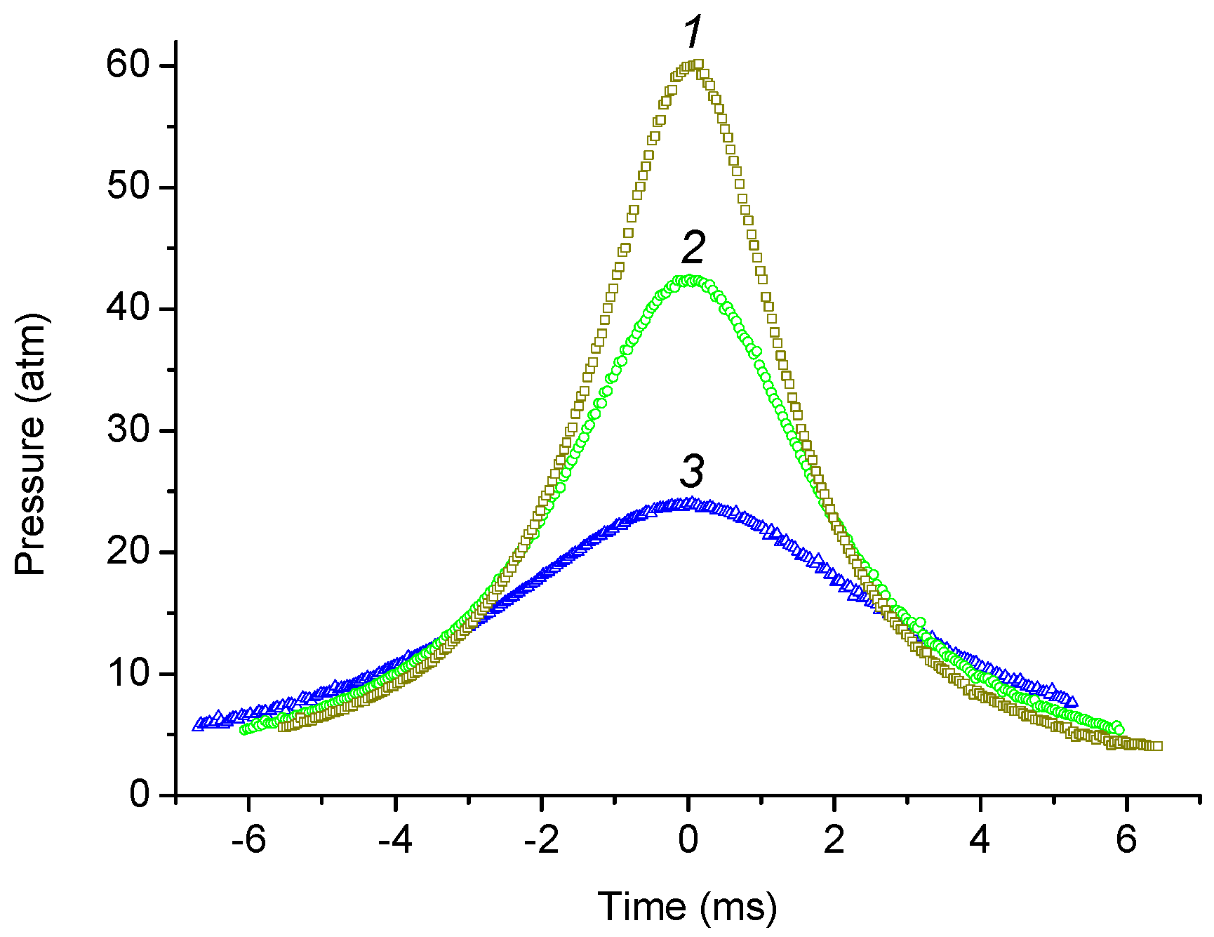
3.1. Pressure–Time History and Calculation of Tmax

Examples of the experimental pressure dependence of the compressible gas P1(t) at different values of the driver gas pressure are shown in Figure 2. The moment of maximum compression was chosen as t = 0, so negative time values correspond to gas compression and positive time values to expansion.
For each experiment, the experimentally determined maximum pressure Pmax of compressible gas and compression ratio εmax were used to calculate the maximum temperature Tmax using the Clapeyron formula:
T m a x = P m a x · V m a x · T 0 P 0 · V 0 = P m a x · T 0 P 0 · ε m a x

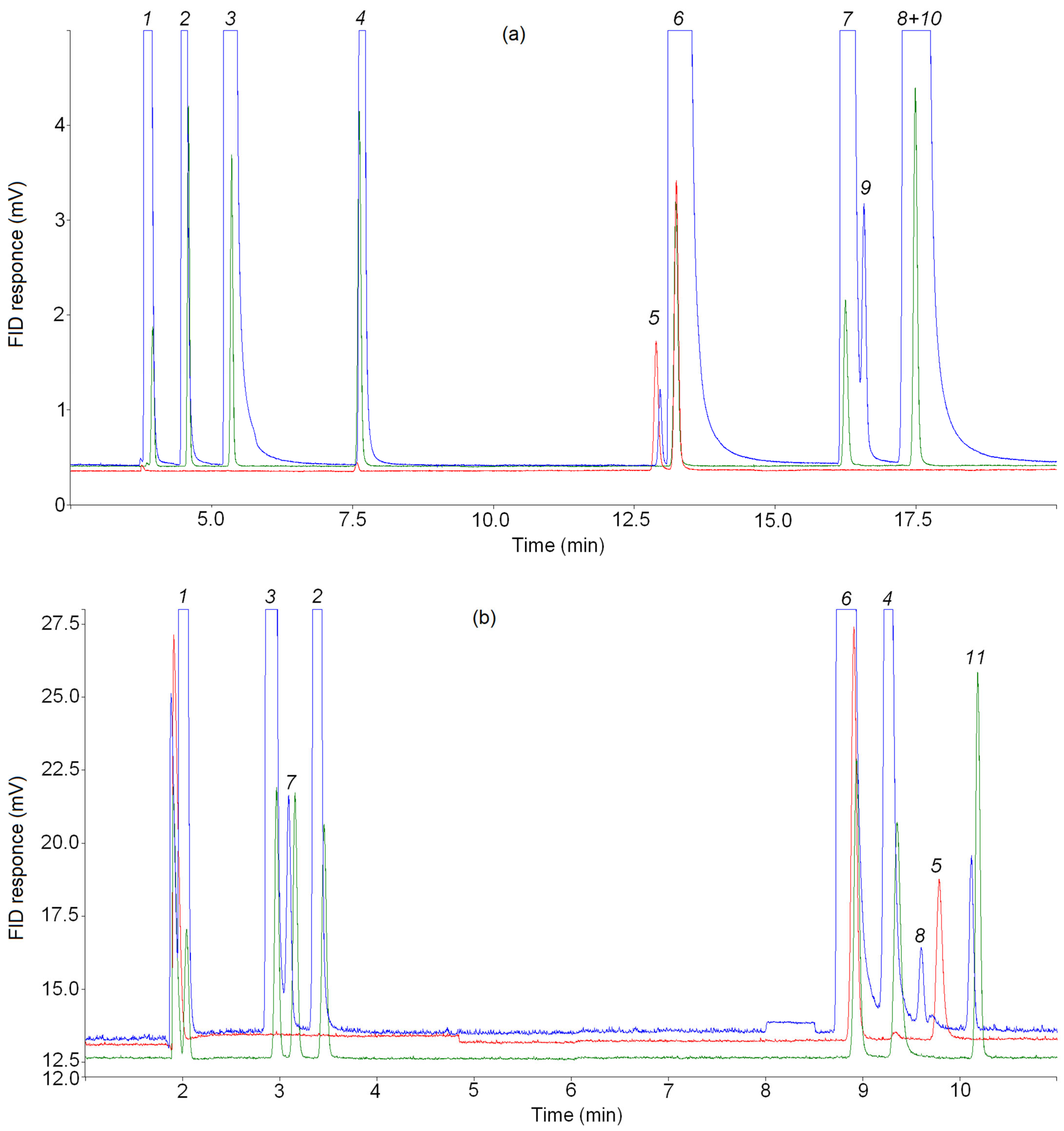
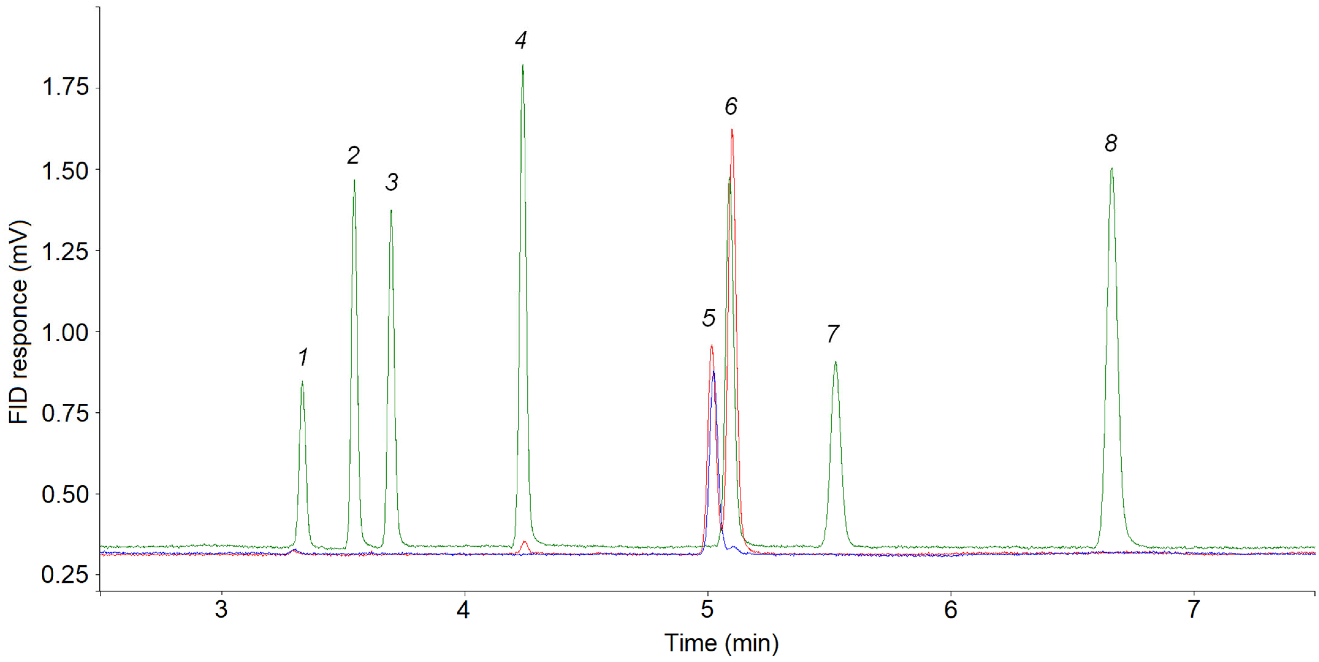
3.2. Choosing of Temperature Programmes for GC Analysis

The choice of chromatographic columns for the separation of product mixtures was guided by the need to ensure the most complete separation of components, including small components, so that the small components are not masked by the main product peaks. For the chemical analysis of a complex mixture of light hydrocarbons, PLOT columns are the most suitable. The use of WCOT columns for this purpose involves cooling the column thermostat initially to negative temperatures. To determine cyclopropane in a complex mixture of light hydrocarbons, it is possible to use columns with methyl silicone phase, for example CP-Sil 5CB [61], but the pyrolysis products of C4–C5 alkanes have high propylene content as well as methyl acetylene and allene; therefore, a small cyclopropane peak, eluting the last of the C3 hydrocarbons, will be masked by peaks of these C3 hydrocarbons. Using PLOT columns with alumina and porous polymers, mixtures of C1–C4 and C1–C3 hydrocarbons, respectively, can be separated to the base line.
It is known that the elution order of light hydrocarbons of different classes on all PLOT columns with alumina remains unchanged in almost all cases, except for the analysis of alkynes and dienes when using an Al2O3/KCl column [62]. For this column, the elution order of the hydrocarbons can vary depending on the temperature program. In the literature, there are many examples of the separation of light hydrocarbon mixtures, including those with cyclopropane, on capillary columns with alumina deactivated with KCl [59,62,63,64,65,66,67,68,69,70]. In all these cases, the order of elution of C3 hydrocarbons was established: propane, cyclopropane, propylene, allene and methylacetylene. Six applications (reference chromatograms) obtained using CP-Al2O3/KCl PLOT capillary columns of different length, inner diameter and thickness of the adsorbent layer are shown in Table 1. These reference chromatograms were obtained in isothermal mode and by programming the oven temperature, with initial temperature values from 40 to 100 °C. The reference chromatograms show peaks of five C3 hydrocarbons (propane, cyclopropane, propylene, allene, methylacetylene) along with other light hydrocarbons. In these reference chromatograms, the cyclopropane peak precedes the propylene peak. When the initial temperature is increased to 130 °C, the cyclopropane and propylene peaks elute together (Application A00273 + [67]). The reverse elution order, i.e., propylene first followed by cyclopropane, is not observed for the CP-Al2O3/KCl PLOT capillary columns.
The analysis of initial mixtures, mixtures of pyrolysis products and reference mixtures using a CP-Al2O3/KCl PLOT capillary column was performed according to the following standard temperature oven program: 100 °C—12 min, temperature rise 8 °C/min to 188 °C. The total analysis time was 60 min or more if necessary. Cyclopropane and propylene peaks were eluted at the first temperature plateau at 100 °C. Thus, conditions were created for their separation as separate peaks. Examples of analyses of light hydrocarbon mixtures, including those involving cyclopropane, are shown in Figure 3, Figure 4a and Figures S3–S6.
In an additional series of experiments on the pyrolysis of n-butane (2a), along with a decrease in reactor temperature to T0 = 323 K (50 °C), the temperature regime of the analysis was changed: the temperature of the gas sampling valves was reduced to 50 °C, and the heating of the metal capillary through which the sample from the reactor was fed to the gas sampling valves was disabled. The temperature program in the column oven was 50 °C—10 min, temperature rise 5 °C/min to 190 °C. The total analysis time was 60 min or more if necessary. Cyclopropane and propylene peaks were separated to the zero line at the first temperature plateau at 50 °C (see Figure 5).
According to the data from the literature, when using a capillary column with a porous polymer of low polarity (phase type Q), C3 hydrocarbons are eluted at a sufficient distance from hydrocarbons C2 and C4 in the following order: propylene, propane, allene, cyclopropane, methylacetylene (Application A01454 + [71])—see also [68,72]. In this work, five C3 hydrocarbons were separated and yielded separate peaks in a column oven under the following temperature program: 40 °C—6 min, temperature rise 10 °C/min to 160 °C, total analysis time 40–50 min (see Figure 4b, Figure 6 and Figure S7).
For a capillary column with a polar porous polymer (U-phase), the elution order of the C3 hydrocarbons was propylene + propane (one peak), cyclopropane, allene, methylacetylene (Applications A01456, CA000C1128 + [73]). In this work, four peaks separated to the zero line were obtained in the C3 hydrocarbon region when heated in a column oven under the following temperature program: 60 °C—5 min, temperature rise 10 °C/min up to 150 °C (Figure 4c and Figure S8).

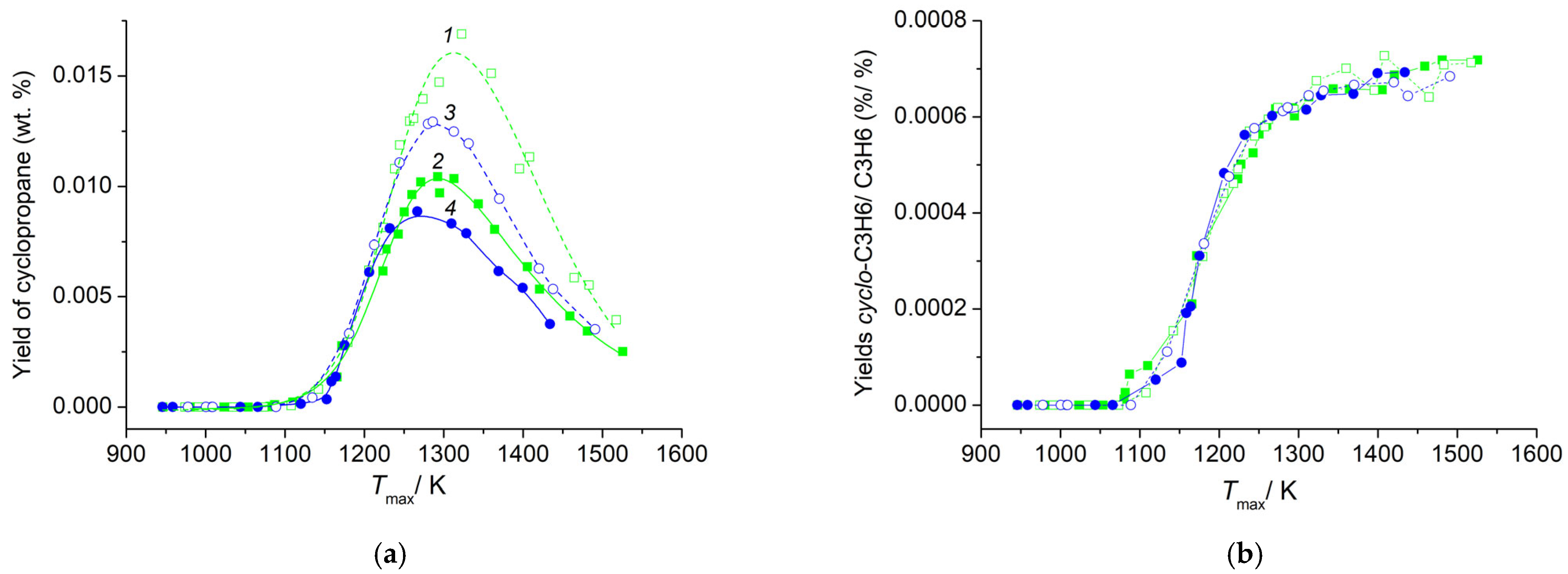
3.3. Cyclopropane Content in a Mixture of Pyrolysis Products of C4–C5 Alkanes

The results of the analysis of pulse pyrolysis product mixtures of isobutane [19], n-butane [20], n-pentane [21], and isopentane [22] in an adiabatic compression reactor show that the main products are: hydrogen, methane, ethylene and propylene (see Figures S1 and S2). At temperatures up to Tmax ≈ 1300 K and correspondingly for alkane conversion degrees ≤ 80%, the main products of pulsed pyrolysis of C4–C5 isoalkanes also include isobutene, and for n-pentane, they include butane-1. Acetylene is added to the main products at a high conversion degree. The list of minor products is quite long, and among them are ethane, propane, allene, methylacetylene, 4 acyclic butenes (butene-1, trans- and cis-butene-2, isobutene), butadiene-1,3, vinyl acetylene, diacetylene, butene-1, butene-2, six acyclic pentenes (pentene-1, trans- and cis-pentene-2, 2-methylbuten-1, 2-methylbuten-2, 3-methylbuten-1), cyclopentene, cyclopentadiene, isoprene, benzene, toluene, etc. [19,20,21,22]. Along with these substances, previously unidentified products were found in a mixture of products. In particular, in the chromatogram obtained using a CP-Al2O3/KCl PLOT capillary column, a small peak before the propylene peak was detected (see Figures S3–S6). According to the chemical analysis there are no molecular oxygen and oxygen-containing organic substances in the initial mixtures; moreover, the highly polar substances are not eluted from the alumina columns [74]. Consequently, this small peak can only correspond to hydrocarbons. A comparison of the retention times of the C2 to C4 hydrocarbons and this unknown peak shows that it can be matched to the C3 hydrocarbon but not to the propane, propylene, allene or methylacetylene, whose retention times have been determined. Reference chromatograms of hydrocarbon mixtures on CP-Al2O3/KCl PLOT capillary columns from the ScanView Application Database [23] show a cyclopropane peak before the propylene peak (see Table 1).
For the final identification of the peak of the unknown C3 hydrocarbon, a chromatographic analysis of mixtures containing cyclopropane was performed under the same GC analysis conditions as the pyrolysis products of C4–C5 alkanes. Figure 4a shows the chromatograms of the pyrolysis product mixture of n-butane (blue line), the mixture 15 ppm cyclo-C3H6/15 ppm C3H6 in Ar (red line) and the reference mixture of 15 ppm CnHm in N2 (green line). As can be seen in this figure, the retention times of cyclopropane and the unknown product are the same. In addition, the retention times of the reference mixture and the known pyrolysis products (CH4, C2H6, C2H4, C2H2, C3H8, C3H6, n-C4H10) present in this chromatogram are identical.
Fir the C3 hydrocarbon retention times, chromatograms of pyrolysis product mixtures obtained with the CP-PoraBOND Q and CP-PoraPLOT U, along with propane, propylene, allene and methylacetylene, also show a small peak attributed to cyclopropane according to reference chromatograms from ScanView [23] (see Figure 4b,c). A comparison of the chromatograms of the product mixtures (blue line), the mixture 15 ppm cyclo-C3H6/15 ppm C3H6 in Ar (red line) and reference mixture 15 ppm CnHm in N2 (green line) confirmed the identification of the unknown C3 hydrocarbon peak as cyclopropane.
In order to rule out the appearance of a small peak before the propylene peak due to thermal degradation processes and misidentification, an additional series of experiments (2a) was carried out on the pyrolysis of n-butane (same mixture) at an initial temperature T0 = 323 K (50 °C). The following were also changed: the temperature regime of injectors and gas sampling valves (the temperature was reduced from 150 °C to 50 °C), the temperature program in the CP-Al2O3/KCl PLOT column oven (the temperature of the initial section at which the separation of propylene and the small peak in front of it were reduced from 100 °C to 50 °C), and the heating of the metal capillary through which the sample was transferred from the reactor into gas sampling valves was turned off. In all cases, a small peak before the propylene peak was detected when separating the product mixture on the CP-Al2O3/KCl PLOT column (see Figure 5a) and between the allene and propylene peaks when separating the product mixture on the CP-PoraBOND Q column (see Figure 5b). Thus, it was shown that the presence of a small peak among C3 hydrocarbons in the chromatograms of the mixture of pyrolysis products of C4–C5 alkanes is not due to temperature effects.
Figure 5. Representative chromatogram from (a) the CP-Al2O3/KCl PLOT and (b) the CP-PoraBOND Q columns, zoomed view. The analysis conditions have changed (see text). Blue line—products of n-butane pyrolysis (additional series at T0 = 323 K), red line—reference mixture cyclo-C3H6/15 ppm C3H6 in Ar, green line—reference mixture 15 ppm CnHm in N2. Note that the larger peaks are off-scale to allow observation of the minor products. Identified compounds: 1 = methane; 2 = ethane; 3 = ethylene; 4 = propane; 5 = cyclopropane; 6 = propylene; 7 = acetylene; 8 = allene; 9 = isobutane; 10 = n-butane, 11 = methylacetylene.
Reactions 04 00023 g005
The small C3 hydrocarbon peak detected on the three PLOT columns cannot be a ghost peak because in the “blank” analysis with argon, there are no peaks in the cyclopropane elution region on any column; the sample fed for analysis is not in contact with the injector (septa, liner, etc.), but is injected from a gas sampling valve directly into the column; the peak identified as cyclopropane is eluted from alumina at an isotherm of 100 °C when analyzed according to the standard program, and at 50 °C when analyzed according to the modified program in an additional series of experiments. There were no acids, bases, alcohols or water in the sample that may have contributed to ghost peaks [75]. There are no peaks caused by previous sample entry—the peak attributed to cyclopropane appeared in the first analysis on all columns.
The dependence of cyclopropane yield on maximum temperature Tmax in a series of experiments with T0 = 393 K began at temperatures 1150–1160 K, passed through the maximum in the range 1270–1320 K, and decreased monotonously up to the end of the temperature interval for all investigated alkanes, C4–C5 (Figure 6a). The initial sections of cyclopropane yield dependence coincided for all investigated alkanes, but the position of maximums and the final sections were different. The maximum yield of cyclopropane increased with the transition from normal alkanes to isoalkanes and from pentanes to butanes. For isobutene, it reached ≈0.017 wt. %, and for n-pentane, 0.009 wt. %. For all investigated alkanes C4–C5, the dependences of the ratio of yields of cyclopropane and propylene Yc-C3H6/YC3H6 monotonically increased with increasing Tmax (Figure 6b). The maximum value of the Yc-C3H6/YC3H6 ratio reached 7 × 10⁻⁴ at high temperatures. According to data from the literature, the yields of cyclopropane during the pyrolysis of cyclopentane are markedly higher. For a mixture with an initial cyclopentane concentration of 5%, the ratio Yc-C3H6/YC3H6 decreases with increasing temperature from 0.14 to 0.018 [41]. During the decomposition of the cyclopentyl radical, the ratio Yc-C3H6/YC3H6 in the products in the temperature range 1060–1116 K ranges from 3 × 10⁻³ to 5 × 10⁻³ [47]. During the decomposition of the 1-pentyl radical, the yield of cyclopropane is approximately 1 × 10⁻³ relative to propylene [46]. The selectivity of cyclopropane for n-butane and isobutane, and for n-pentane and isopentane, coincides in pairs to a conversion degree of alkane of ≈25% and 30%, respectively (Figure 7). It is seen that in the pyrolysis of C4–C5 acyclic alkanes, cyclopropane is not a primary product, in contrast to the pyrolysis of cyclopentane [41] and the decomposition of cyclopentyl radical [47]. The selectivities of cyclopropane during the pyrolysis of n-butane in two series of experiments at different initial temperatures T0 = 393 K (shaded squares 2) and T0 = 323 K (shaded rhombus 2a) are similar in shape and differ in the position of the maximum. The results obtained testify not only to the low content of cyclopropane in the products of pulse pyrolysis of acyclic alkanes C4–C5, but also to the difference in the mechanism of its formation compared to the pyrolysis of cyclopentane.
Figure 6. Temperature dependence of the cyclopropane yield (a) and Yc-C3H6/YC3H6 (b). Open squares (1), closed squares (2), open circle (3) and closed circles (4) represent the weight content of cyclopropane produced during the pyrolysis of isobutane, n-butane, isopentane and n-pentane, respectively. Initial temperature T0 = 393 K.
Reactions 04 00023 g006
Figure 7. Selectivity of the cyclopropane. Symbols (1)–(4) are the same as in Figure 6. The closed rhombus (2a) represents the selectivity of the cyclopropane produced during the pyrolysis of n-butane at the initial temperature T0 = 323 K.
Reactions 04 00023 g007
Thus, among the products of the pyrolysis of n-butane, isobutane, n-pentane and isopentane, cyclopropane was found for the first time in small quantities. Surprisingly, a stressed cyclic hydrocarbon is formed in the non-selective gas-phase pyrolysis process of alkanes. The presence of cyclopropane in the pyrolysis products of alkanes means that the rate of its formation is comparable to the rate of decline. It is known that at high temperatures, cyclopropane is rapidly isomerized into propylene, so the rate of the formation of cyclopropane should also be high enough. Detailed kinetic mechanisms involving cyclopropane are discussed in the literature [76,77,78], but all of them were developed for modeling ignition delays, and are not adapted for the study of the kinetics of cyclopropane formation in an oxygen-free environment. The question about the mechanism of cyclopropane formation under the conditions of pulse pyrolysis of alkanes remains open. Further theoretical and experimental investigations are desirable to establish the mechanism of this reaction.

4. Conclusions

The pulsed pyrolysis of C4–C5 alkanes with normal and isomeric structures was studied in an adiabatic compression reactor with a free flying piston. The composition of the pulsed pyrolysis products was investigated by gas chromatography. The analysis of the hydrocarbon part of the products was carried out using three capillary columns of different polarity and selectivity, and sufficient efficiency to separate all C1–C4 hydrocarbons (CP-Al2O3/KCl PLOT column) and C1–C3 hydrocarbons (CP-PoraBOND Q and CP-PoraPLOT columns). Cyclopropane was found among the pyrolysis products for the first time. The identification of cyclopropane in the products of pulsed pyrolysis of C4–C5 alkanes was carried out by analyzing mixtures containing cyclopropane and other C1–C4 hydrocarbons under the same conditions as the standard analysis of a mixture of products. The peak attributed to cyclopropane cannot be a ghost peak. This was confirmed in a series of experiments on the pyrolysis of n-butane with a reduced initial temperature of the adiabatic compression reactor (from 120 °C to 50 °C) and a modified GC analysis mode.
Cyclopropane yields, as a function of maximum temperature, show a bell-shaped, asymmetrical dependence. The maximum yield of cyclopropane increases with the transition from normal alkanes to isoalkanes and from pentanes to butanes. For isobutene, it reaches ≈0.017 wt. %, and for n-pentane, 0.009 wt. %. Cyclopropane is not a primary product of the pyrolysis of isobutane, n-butane, isopentane or n-pentane, unlike cyclopentane.
Thus, the conducted studies indicate the formation of cyclopropane during the pyrolysis of C4–C5 alkanes with normal and isomeric structures. Further theoretical and experimental studies are desirable to establish the mechanism of this reaction. It should be noted that substances such as cyclopropane can be detected in a mixture of products during rapid cooling (quenching), which was successfully implemented in the method of the adiabatic compression of gases with a free flying piston.

Supplementary Materials

The following supporting information can be downloaded at: https://www.mdpi.com/article/10.3390/reactions4030023/s1, Figure S1: Representative chromatograms of n-butane pyrolysis products and the initial mixture from the CP-Al2O3/KCl PLOT column under standard analysis conditions; Figure S2: Representative chromatograms of isobutane pyrolysis products and the initial mixture from the CP-Al2O3/KCl PLOT column under standard analysis conditions; Figure S3: Representative chromatograms of n-butane pyrolysis products and the initial mixture from the CP-Al2O3/KCl PLOT column under standard analysis conditions—zoomed view; Figure S4: Representative chromatograms of isobutane pyrolysis products and the initial mixture from the CP-Al2O3/KCl PLOT column under standard analysis conditions—zoomed view; Figure S5: Representative chromatograms of n-pentane pyrolysis products and the initial mixture from the CP-Al2O3/KCl PLOT column under standard analysis conditions—zoomed view; Figure S6: Representative chromatograms of isopentane pyrolysis products and the initial mixture from the CP-Al2O3/KCl PLOT column under standard analysis conditions—zoomed view; Figure S7: Representative chromatograms of isobutane pyrolysis products and the initial mixture from the CP-PoraBOND Q column under standard analysis conditions—zoomed view; Figure S8: Representative chromatograms of isobutane pyrolysis products and the initial mixture from the CP-PoraPLOT U column—zoomed view.

Funding

This work was carried out within the State Program for the TIPS RAS.

Data Availability Statement

The data presented in this study are available on request from the corresponding author. The data are not publicly available due to restrictions privacy.

Conflicts of Interest

The authors declare no conflict of interest.

References

  1. Longwell, P.A.; Reamer, H.H.; Wilburn, N.P.; Sage, B.H. Ballistic piston for investigating gas phase reactions. Ind. Eng. Chem. 1958, 50, 603–610. [Google Scholar] [CrossRef]
  2. Markevich, A.M.; Azatyan, V.V.; Sokolova, N.A. Adiabatic compression as a method for studying chemical processes under nonstationary conditions. Kinet. Catal. 1962, 3, 431–438. [Google Scholar]
  3. Volokhonovich, I.E.; Markevich, A.M.; Masterovoy, I.F.; Azatyan, V.V. Non-isothermal processes. Thermal cracking of methane. Dokl. USSR 1962, 146, 387–390. [Google Scholar]
  4. Kondratiev, V.N. Determination of the rate constant for thermal cracking of methane by means of adiabatic compression and expansion. Symp. Int. Combust. 1965, 10, 319–322. [Google Scholar] [CrossRef]
  5. Buravtsev, N.N.; Grigor’ev, A.S.; Kolbanovskii, Y.A. Kinetics of the cyclodimerization of tetrafluoroethylene and the thermal decomposition of octafluorocyclobutane. Kinet. Catal. 1985, 26, 1–7. [Google Scholar]
  6. Buravtsev, N.N.; Grigor’ev, A.S.; Kolbanovskii, Y.A. Kinetics and mechanism of pyrolysis of hexafluoropropylene. Kinet. Catal. 1989, 30, 13–22. [Google Scholar]
  7. Kuptsova, T.S.; Buravtsev, N.N.; Chernyak, N.Y.; Shapiro, E.A.; Kolbanovskii, Y.u.A.; Nefedov, O.M. Thermal isomerization of 3,3-dimethylcyclopropene under adiabatic-compression conditions. Russ. Chem. Bull. 1989, 38, 1845–1847. [Google Scholar] [CrossRef]
  8. Kolbanovskiy, Y.A. Adiabatic compression in studies on the kinetics and mechanism of reactions involving fluorine-containing carbenes. Russ. Chem. Rev. 1989, 58, 1024–1032. [Google Scholar] [CrossRef]
  9. Ryabinin, Y.N. Gases at High Densities and Temperatures; Pergamon Press, Inc.: New York, NY, USA, 1961; 52p. [Google Scholar]
  10. Lalos, G.T.; Hammond, G.L. The Ballistic Compression and High Temperature Properties of Dense Gases. In Experimental Thermodynamics, Volume II. Experimental Thermodynamics of Non-Reacting Fluids; Le Neindre, B., Vodar, B., Eds.; Springer Science + Business Media: New York, NY, USA, 1975; pp. 1193–1218. [Google Scholar]
  11. Kolbanovskiy, Y.A.; Shchipachev, V.S.; Chernyak, N.Y.; Chernyshova, A.S.; Grigor’ev, A.S. Impulsive Compression of Gases in Chemistry and Technology; Science: Moscow, Russia, 1982; 240p. (In Russian) [Google Scholar]
  12. Buravtsev, N.N.; German, L.S.; Grigor’ev, A.S.; Kolbanovskii, Y.A.; Ovsyannikov, A.A.; Volkonskii, A.Y. Trifluoromethylfluorocarbene Formation and Reactions under C2F5SiF3 Pulsed Adiabatic Compression Pyrolysis. Mendeleev Commun. 1993, 3, 133–134. [Google Scholar] [CrossRef]
  13. Slotboom, Y.; Roosjen, S.; Kronberg, A.; Glushenkov, M.; Kersten, S.R.A. Methane to ethylene by pulsed compression. Chem. Eng. J. 2021, 414, 128821. [Google Scholar] [CrossRef]
  14. Drost, S.; Schießl, R.; Maas, U. Multi compression–expansion process for chemical energy conversion: Transformation of methane to unsaturated hydrocarbons and hydrogen. Appl. Energy Combust. Sci. 2023, 14, 100129. [Google Scholar] [CrossRef]
  15. Porras, S.; Kaczmarek, D.; Herzler, J.; Drost, S.; Werler, M.; Kasper, T.; Fikri, M.; Schießl, R.; Atakan, B.; Schulz, C.; et al. An experimental and modeling study on the reactivity of extremely fuel-rich methane/dimethyl ether mixtures. Combust. Flame 2020, 212, 107–122. [Google Scholar] [CrossRef]
  16. Ezdin, B.S.; Vasiljev, S.A.; Yatsenko, D.A.; Fedorov, V.E.; Ivanova, M.N.; Kalyada, V.V.; Pakharukov, Y.V.; Shabiev, F.K.; Zarvin, A.E. The Synthesis of Carbon Nanoparticles in a Compression Reactor in the Atmosphere of Buffer Gases. Sib. J. Phys. 2022, 17, 29–46. [Google Scholar] [CrossRef]
  17. Rudolph, C.; Atakan, B. Pyrolysis of Methane and Ethane in a Compression–Expansion Process as a New Concept for Chemical Energy Storage: A Kinetic and Exergetic Investigation. Energy Technol. 2021, 9, 2000948. [Google Scholar] [CrossRef]
  18. Ashok, A.; Katebah, M.A.; Linke, P.; Kumar, D.; Arora, D.; Fischer, K.; Jacobs, T.; Al-Rawashdeh, M. Review of piston reactors for the production of chemicals. Rev. Chem. Eng. 2023, 39, 1–30. [Google Scholar] [CrossRef]
  19. Bilera, I.V.; Buravtsev, N.N. The homogeneous pyrolysis of isobutane under pulsed adiabatic compression. Gorenie Vzryv. Mosk.—Combust. Explos. 2013, 6, 37–40. [Google Scholar]
  20. Bilera, I.V. The homogeneous pyrolysis of n-butane under pulsed adiabatic compression. Gorenie Vzryv. Mosk.—Combust. Explos. 2014, 7, 35–41. [Google Scholar]
  21. Bilera, I.V. The homogeneous pyrolysis of n-pentane under pulsed adiabatic compression. Gorenie Vzryv. Mosk.—Combust. Explos. 2015, 8, 97–105. [Google Scholar]
  22. Bilera, I.V.; Buravtsev, N.N. The homogeneous pyrolysis of isopentane under pulsed adiabatic compression. Gorenie Vzryv. Mosk.—Combust. Explos. 2016, 9, 74–82. [Google Scholar]
  23. ScanView—Online eLibrary (Agilent Technologies). The Fully Updated 2018 Version Is Available and Is Hosted in Agilent Community. Available online: https://community.agilent.com (accessed on 16 October 2018).
  24. Allara, D.L.; Edelson, D. A Computational Modeling Study of the Low-Temperature Pyrolysis of n-Alkanes; Mechanisms of Propane, n-Butane, and n-Pentane Pyrolyses. Int. J. Chem. Kinet. 1975, 7, 479–507. [Google Scholar] [CrossRef]
  25. Safarik, I.; Strausz, O.P. The thermal decomposition of hydrocarbons. Part 1. n-alkanes (C ≥ 5). Res. Chem. Intermed. 1996, 22, 275–314. [Google Scholar] [CrossRef]
  26. Dente, M.; Bozzano, G.; Faravelli, T.; Marongiu, A.; Pierucci, S.; Ranzi, E. Kinetic Modelling of Pyrolysis Processes in Gas and Condensed Phase. Adv. Chem. Eng. 2007, 32, 51–166. [Google Scholar] [CrossRef]
  27. Hou, X.; Song, C.; Ma, Z.; Chen, B.; Zhao, L.; Huang, J.; Yuan, E.; Cui, T. Universality analysis of the reaction pathway and product distribution in C5–C10 n-alkanes pyrolysis. J. Anal. Appl. Pyrolysis 2022, 162, 105451. [Google Scholar] [CrossRef]
  28. Zamostny, P.; Belohlav, Z.; Starkbaumova, L.; Patera, J. Experimental study of hydrocarbon structure effects on the composition of its pyrolysis products. J. Anal. Appl. Pyrolysis 2010, 87, 207–216. [Google Scholar] [CrossRef]
  29. Yanovskaya, L.A.; Dombrovskii, V.A. Functionally Substituted Cyclopropanes. Russ. Chem. Rev. 1975, 44, 154–169. [Google Scholar] [CrossRef]
  30. Lebel, H.; Marcoux, J.-F.; Molinaro, C.; Charette, A.B. Stereoselective Cyclopropanation Reactions. Chem. Rev. 2003, 103, 977–1050. [Google Scholar] [CrossRef]
  31. Vogel, E. Kleine Kohlenstoff-Ringe. Angew. Chem. 1960, 72, 4–26. [Google Scholar] [CrossRef]
  32. Engel, P.S. Mechanism of the thermal and photochemical decomposition of azoalkanes. Chem. Rev. 1980, 80, 99–150. [Google Scholar] [CrossRef]
  33. Elinson, M.N.; Dorofeeva, E.O.; Vereshchagin, A.N.; Nikishin, G.I. Electrochemical synthesis of cyclopropanes. Russ. Chem. Rev. 2015, 84, 485–497. [Google Scholar] [CrossRef]
  34. Ebner, C.; Carreira, E.M. Cyclopropanation Strategies in Recent Total Syntheses. Chem. Rev. 2017, 117, 11651–11679. [Google Scholar] [CrossRef]
  35. Lott, W.A.; Christiansen, W.G. The preparation of cyclopropane. J. Am. Pharm. Assoc. 1930, 19, 341–344. [Google Scholar] [CrossRef]
  36. Setser, D.W.; Rabinovitch, B.S. Singlet methylene from thermal decomposition of diazomethane. Unimolecular reactions of chemically activated cyclopropane and dimethylcyclopropane molecules. Can. J. Chem. 1962, 40, 1425–1451. [Google Scholar] [CrossRef]
  37. Setser, D.W.; Rabinovitch, B.S.; Simons, J.W. Collisional Transition Probabilities for Deactivation of Highly Vibrationally Excited Cyclopropane and Dimethylcyclopropane. J. Chem. Phys. 1964, 40, 1751–1761. [Google Scholar] [CrossRef]
  38. Crawford, R.J.; Mishra, A. The Mechanism of the Thermal Decomposition of 1-Pyrazolines and Its Relationship to Cyclopropane Isomerizations. J. Am. Chem. Soc. 1966, 88, 3963–3969. [Google Scholar] [CrossRef]
  39. Campbell, R.J.; Schlag, E.W.; Ristow, B.W. Mechanistic consequences of curved Stern–Volmer plots. The photolysis of cyclobutanone. J. Am. Chem. Soc. 1967, 89, 5098–5102. [Google Scholar] [CrossRef]
  40. Blades, A.T. Kinetics sf the thermal decomposition of cyclobutanone. Can. J. Chem. 1969, 47, 615–617. [Google Scholar] [CrossRef]
  41. Tsang, W. Thermal decomposition of cyclopentane and related compounds. Int. J. Chem. Kinet. 1978, 10, 599–617. [Google Scholar] [CrossRef]
  42. Gusel’nikov, L.E.; Volkova, V.V.; Ivanov, P.E.; Inyushkin, S.V.; Shevelkova, L.V.; Zimmermann, G.; Ziegler, U.; Ondruschka, B. Direct infrared spectroscopic evidence of allyl radical and definition of the initiation step in thermal decomposition of cycloalkanes. A comparison with very low pressure pyrolysis of alkenes. J. Anal. Appl. Pyrolysis 1991, 21, 79–93. [Google Scholar] [CrossRef]
  43. Tsang, W. Thermal stability of cyclohexane and 1-hexene. Int. J. Chem. Kinet. 1978, 10, 1119–1138. [Google Scholar] [CrossRef]
  44. Wang, Z.; Cheng, Z.; Yuan, W.; Cai, J.; Zhang, L.; Zhang, F.; Qi, F.; Wang, J. An experimental and kinetic modeling study of cyclohexane pyrolysis at low pressure. Combust. Flame 2012, 159, 2243–2253. [Google Scholar] [CrossRef] [Green Version]
  45. Awan, I.A.; McGivern, W.S.; Tsang, W.; Manion, J.A. Decomposition and isomerization of 5-methylhex-1-yl radical. J. Phys. Chem. A 2010, 114, 7832–7846. [Google Scholar] [CrossRef]
  46. Awan, I.A.; Burgess, D.R., Jr.; Manion, J.A. Pressure Dependence and Branching Ratios in the Decomposition of 1-Pentyl Radicals: Shock Tube Experiments and Master Equation Modeling. J. Phys. Chem. A 2012, 116, 2895–2910. [Google Scholar] [CrossRef]
  47. Awan, I.A.; Burgess, D.R., Jr.; Tsang, W.; Manion, J.A. Shock tube study of the decomposition of cyclopentyl radicals. Proc. Combust. Inst. 2011, 33, 341–349. [Google Scholar] [CrossRef]
  48. Manion, J.A.; Awan, I.A. A Shock tube study of H atom addition to cyclopentene. Int. J. Chem. Kinet. 2018, 50, 225–242. [Google Scholar] [CrossRef]
  49. Markus, M.W.; Woiki, D.; Roth, P. Two-channel thermal decomposition of CH3. Proc. Combust. Inst. 1992, 24, 581–588. [Google Scholar] [CrossRef]
  50. Saldana, M.H.; Bogin, G.E., Jr. Investigation of n-pentane pyrolysis at elevated temperatures and pressures in a variable pressure flow reactor. J. Anal. Appl. Pyrolysis 2016, 118, 286–297. [Google Scholar] [CrossRef] [Green Version]
  51. Zhang, Y.-J.; Yuan, W.-H.; Cai, J.-H.; Zhang, L.-D.; Qi, F.; Li, Y.-Y. Product identification and mass spectrometric analysis of n-butane and i-butane pyrolysis at low pressure. Chin. J. Chem. Phys. 2013, 26, 151–156. [Google Scholar] [CrossRef]
  52. Li, W.; Wang, G.; Li, Y.; Li, T.; Zhang, Y.; Cao, C.; Zou, J.; Law, C.K. Experimental and kinetic modeling investigation on pyrolysis and combustion of n-butane and i-butane at various pressures. Combust. Flame 2018, 191, 126–141. [Google Scholar] [CrossRef]
  53. Goos, E.; Hippler, H.; Hoyermann, K.; Jürges, B. Laser powered homogeneous pyrolysis of butane initiated by methyl radicals in a quasi-wall-free reactor at 750–1000 K. Phys. Chem. Chem. Phys. 2000, 2, 5127–5132. [Google Scholar] [CrossRef]
  54. Khan, Z.A.; Hellier, P.; Ladommatos, N.; Almaleki, A. Sampling of Gas-Phase Intermediate Pyrolytic Species at Various Temperatures and Residence Times during Pyrolysis of Methane, Ethane, and Butane in a High-Temperature Flow Reactor. Sustainability 2023, 15, 6183. [Google Scholar] [CrossRef]
  55. Sirjean, B.; Glaude, P.A.; Ruiz-Lopez, M.F.; Fournet, R. Detailed kinetic study of the ring opening of cycloalkanes by CBS-QB3 calculations. J. Phys. Chem. A 2006, 110, 12693–12704. [Google Scholar] [CrossRef] [PubMed] [Green Version]
  56. Alkidas, A.C.; Plett, E.G.; Summerfieldt, M. Performance study of a ballistic compressor. AIAA J. 1976, 14, 1752–1758. [Google Scholar] [CrossRef]
  57. Price, D.; Lalos, G.T. Adiabatic compressor for P-V-T measurements on gases to 100,000 pounds per square inch. Ind. Eng. Chem. 1957, 49, 1987–1992. [Google Scholar] [CrossRef]
  58. Castello, G.; Vezzani, S.; Gardella, L. Influence of temperature on the polarity of porous polymer beads stationary phases for gas chromatography. J. Chromatogr. A 1999, 837, 153–170. [Google Scholar] [CrossRef]
  59. Ji, Z.; Majors, R.E.; Guthrie, E.J. Porous layer open-tubular capillary columns: Preparations, applications and future directions. J. Chromatogr. A 1999, 842, 115–142. [Google Scholar] [CrossRef]
  60. Grob, R.L.; Kaiser, M.A. Qualitative and Quantitative Analysis by Gas Chromatography. In Modern Practice of Gas Chromatography, 4th ed.; Grob, R.L., Barry, E.F., Eds.; John Wiley & Sons, Inc.: Hoboken, NJ, USA, 2004; pp. 403–460. [Google Scholar]
  61. Do, L.; Raulin, F. Gas chromatography of Titan’s atmosphere. III. Analysis of low-molecular-weight hydrocarbons and nitriles with a CP-Sil5 CB WCOT capillary column. J. Chromatogr. 1992, 591, 297–301. [Google Scholar] [CrossRef]
  62. Armstrong, D.W.; Reid, G.L.; Luong, J. Gas Separations: A Comparison of GasPro™ and Aluminum Oxide PLOT Columns for the Separation of Highly Volatile Compounds. Curr. Sep. 1996, 15, 5–11. Available online: http://www.currentseparations.com/issues/15-1/cs15-1a.pdf (accessed on 16 March 2023).
  63. Ji, Z.; Chang, I. A New Look at Light Hydrocarbon Separations on Commercial Alumina PLOT Columns: Column Selectivity and Separation. J. High Resolut. Chromatogr. 1996, 19, 32–36. [Google Scholar] [CrossRef]
  64. Schneider, W.; Frone, J.; Bruderreck, H. Determination of hydrocarbons in the parts per 109 range using glass capillary columns coated with aluminium oxide. J. Chromatogr. 1978, 155, 311–327. [Google Scholar] [CrossRef]
  65. De Nijs, R.C.M. Analysis of Light Hydrocarbons C1-C5 with Porous Layer Open Tubular Fused Silica Columns of Aluminum Oxide. J. High Resolut. Chromatogr. 1981, 4, 612–615. [Google Scholar] [CrossRef]
  66. De Nijs, R.C.M.; De Zeeuw, J. Aluminium oxide-coated fused-silica porous-layer open-tubular column for gas-solid chromatography of C1-C10 hydrocarbons. J. Chromatogr. 1983, 279, 41–48. [Google Scholar] [CrossRef]
  67. De Zeeuw, J.; De Nijs, R.C.M.; Henrich, L.T. Adsorption Chromatography on PLOT (Porous-Layer Open-Tubular) Columns: A New Look at the Future of Capillary GC. J. Chromatogr. Sci. 1987, 25, 71–83. [Google Scholar] [CrossRef]
  68. Henrich, L.H. Recent Advances in Adsorption Chromatography for Analysis of Light Hydrocarbons in Petrochemical-Related Materials. J. Chromatogr. Sci. 1988, 26, 198–205. [Google Scholar] [CrossRef]
  69. Schaeffer, H.-J. Gas Chromatographic Analysis of Traces of Light Hydrocarbons. A Review of Different Systems in Practice. J. High Resolut. Chromatogr. 1989, 12, 69–81. [Google Scholar] [CrossRef]
  70. De Zeeuw, J.; Luong, J. Developments in stationary phase technology for gas chromatography. Trends Anal. Chem. 2002, 21, 594–607. [Google Scholar] [CrossRef]
  71. Tang, Y.-Z.; Tran, Q.; Fellin, P.; Cheng, W.K.; Drummond, I. Determination of C1–C4 hydrocarbons in air. Anal. Chem. 1993, 65, 1932–1935. [Google Scholar] [CrossRef]
  72. Do, L.; Raulin, F. Gas chromatography of Titan’s atmosphere. I. Analysis of low-molecular-weight hydrocarbons and nitriles with a PoraPLOT Q porous polymer coated open-tubular capillary column. J. Chromatogr. 1989, 481, 45–54. [Google Scholar] [CrossRef]
  73. Ji, Z.; Hutt, S. A New Bonded Porous Polymer PLOT U Column with Increased Polarity. J. Chromatogr. Sci. 2000, 38, 496–502. [Google Scholar] [CrossRef] [Green Version]
  74. Ruan, Z.; Liu, H.J. Preparation of 4-vinylpyridine and divinylbenzene porous-layer open tubular columns by in situ copolymerization. J. Chromatogr. 1995, 693, 79–88. [Google Scholar] [CrossRef]
  75. Kumar, A.; Sharma, C. Recent update of the various sources originating ghost peaks in gas chromatography: A review. J. Chromatogr. A 2022, 1685, 463625. [Google Scholar] [CrossRef]
  76. Battin-Leclerc, F. Detailed chemical kinetic models for the low-temperature combustion of hydrocarbons with application to gasoline and diesel fuel surrogates. Progr. Energy Combust. Sci. 2008, 34, 440–498. [Google Scholar] [CrossRef] [Green Version]
  77. Vlasov, P.A.; Garmash, A.A.; Tereza, A.M. Ignition of Cyclopropane in Shock Waves. Russ. J. Phys. Chem. B 2016, 10, 602–614. [Google Scholar] [CrossRef]
  78. Wang, R.; Xu, P.; Tang, W.; Ding, T.; Zhang, C.; Li, X. An experimental and kinetic study of the ignition delay characteristics of cyclopropane in air. Fuel 2022, 319, 123784. [Google Scholar] [CrossRef]
Figure 1. Schematic diagram of the experimental setup. 1—cylinder, 2—piston, 3—a compression degree indicator, 4—driver gas receiver, 5—valve, 6—manometer, 7—back-pressure valve, 8—feedstock container, 9—air thermostat, 10—pressure transducer, 11—charge amplifier, 12—analog-to-digital converter, 13—personal computer, 14 and 15—gas chromatographs, 16—heated capillary.
Reactions 04 00023 g001
Figure 2. Comparison of pressure dependencies during adiabatic compression of a mixture of 2.0% vol. n-butane, 98% argon. T0 = 393 K (120 °C). Pressures of driver gas: 1—12.0 atm; 2—10.0 atm; 3—7.0 atm. Skip 2 points on the pressure dependences.
Reactions 04 00023 g002
Figure 3. Separations of C1–C3 hydrocarbons on the CP-Al2O3/KCl PLOT column. Blue line—reference mixture 15 ppm cyclopropane in Ar, red line—reference mixture 15 ppm cyclopropane + 15 ppm propylene in Ar, green line—reference mixture 15 ppm CnHm in N2. Peaks: 1 = methane; 2 = ethane; 3 = ethylene; 4 = propane; 5 = cyclopropane; 6 = propylene; 7 = acetylene; 8 = n-butane.
Reactions 04 00023 g003
Figure 4. Separations of C3 hydrocarbons on (a) the CP-Al2O3/KCl PLOT, (b) the CP-PoraBOND Q and (c) the CP-PoraPLOT U columns. Blue line—products of n-butane pyrolysis, red line—reference mixture cyclo-C3H6/15 ppm C3H6 in Ar, green line—reference mixture 15 ppm CnHm in N2. Note that the larger peaks are off-scale to allow observation of the minor substances. Peaks: 1 = methane; 2 = ethane; 3 = ethylene; 4 = propane; 5 = cyclopropane; 6 = propylene; 7 = acetylene; 8 = allene; 9 = isobutane; 10 = n-butane, 11 = methylacetylene, 12 = unknown substance.
Reactions 04 00023 g004aReactions 04 00023 g004b
Table 1. Application numbers from the ScanView Application Database [23] used for comparison with chromatograms.
GC ColumnApplication No.
CP-Al2O3/KCl PLOTA00155, A00677, A01099, A01123, A01124, A01545
CP-PoraBOND QA01454
CP-PoraPLOT UA01456, CA000C1128
Disclaimer/Publisher’s Note: The statements, opinions and data contained in all publications are solely those of the individual author(s) and contributor(s) and not of MDPI and/or the editor(s). MDPI and/or the editor(s) disclaim responsibility for any injury to people or property resulting from any ideas, methods, instructions or products referred to in the content.

