Review

Low-Dimensional Nanostructures for Electrochemical Energy Applications

1
Department of Applied Physics and Chemistry, University of Taipei, Taipei 10048, Taiwan
2
Department of Chemistry, National Taiwan University, Taipei 10617, Taiwan
*
Authors to whom correspondence should be addressed.
These authors contributed equally.
Physics 2020, 2(3), 481-502; https://doi.org/10.3390/physics2030027
Submission received: 28 July 2020 / Revised: 31 August 2020 / Accepted: 4 September 2020 / Published: 11 September 2020
(This article belongs to the Section Applied Physics)

Abstract

:
Materials with different nanostructures can have diverse physical properties, and they exhibit unusual properties as compared to their bulk counterparts. Therefore, the structural control of desired nanomaterials is intensely attractive to many scientific applications. In this brief review, we mainly focus on reviewing our recent reports based on the materials of graphene and the transition metal chalcogenide, which have various low-dimensional nanostructures, in relation to the use of electrocatalysts in electrochemical energy applications; moreover, related literatures were also partially selected for discussion. In addition, future aspects of the nanostructure design related to the further enhancement of the performance of pertinent electrochemical energy devices will also be mentioned.

1. Introduction

Since 2004, graphene has been unambiguously produced and identified, soon causing a boom in global research on two-dimensional materials [1]. Graphene shows great potential in electronics, composites, and catalysis due to its great conductivity, high electron mobility, and high surface area [2]. According to quantum mechanics, finite-size effects have been theoretically predicted and experimentally confirmed. Many studies have utilized a new type of graphene nanostructure, graphene quantum dots (GQDs), whose sizes are smaller than 100 nm [3]. GQDs exhibit great crystallinity, preserving the promising chemical and physical properties of graphene. A recent report revealed that the addition of GQD in counter electrodes (CEs) increased the efficiency in dye-sensitized solar cells (DSSCs) due to the improvement of the catalytic activity and the increase of the electrocatalytic surface area. Owing to quantum confinement and edge effects, GQDs have generated great interest in photovoltaics and light-emitting diodes (LED) applications [4]. On the other hand, 3-dimensional (3D) graphene materials such as graphene hollow balls have recently been produced for the improvement of the electrocatalytic activity and surface area in electrocatalysis applications [5]. Transition metal dichalcogenides (TMDCs), two-dimensional layered semiconductor materials with a chemical bond within an in-plane structure and an attraction by Van der Waals force between layers, have attracted much attention in recent years. For example, molybdenum disulfide (MoS2), tungsten disulfide (WS2), molybdenum diselenide (MoSe2), and tungsten diselenide (WSe2) are noted for their low cost, abundance and easy processing. 1-dimensional (1D) TMDCs, such as nanowires (NWs), nanotubes (NTs), and nanoneedles (NDs), play a significant role in nanoscale electronic or photoelectronic devices due to their fast charge transporting property [6,7,8]. TMDCs have been investigated as potential materials to replace platinum (Pt) as electrocatalysts in hydrogen evolution reactions (HERs) because they are earth-abundant and possess excellent electrochemical properties [9,10,11]. Meanwhile, 2-dimensional (2D) materials with a high surface area and high conductivity have also attracted much attention in recent years. There is a transformation from indirect bandgap to direct bandgap when 2D materials are stripped from bulk ones to monolayers [12]. Studies have shown that 2D materials show promise in catalysis and energy storage because of their unique properties and structure [13,14]. In this article, the different dimensions of graphene and TMDC materials in electrochemical applications will be briefly reviewed.

2. Zero-Dimensional Graphene Material for the Counter Electrode of Dye-Sensitized Solar Cells

2.1. Graphene Quantum Dot-Doped Polypyrrole

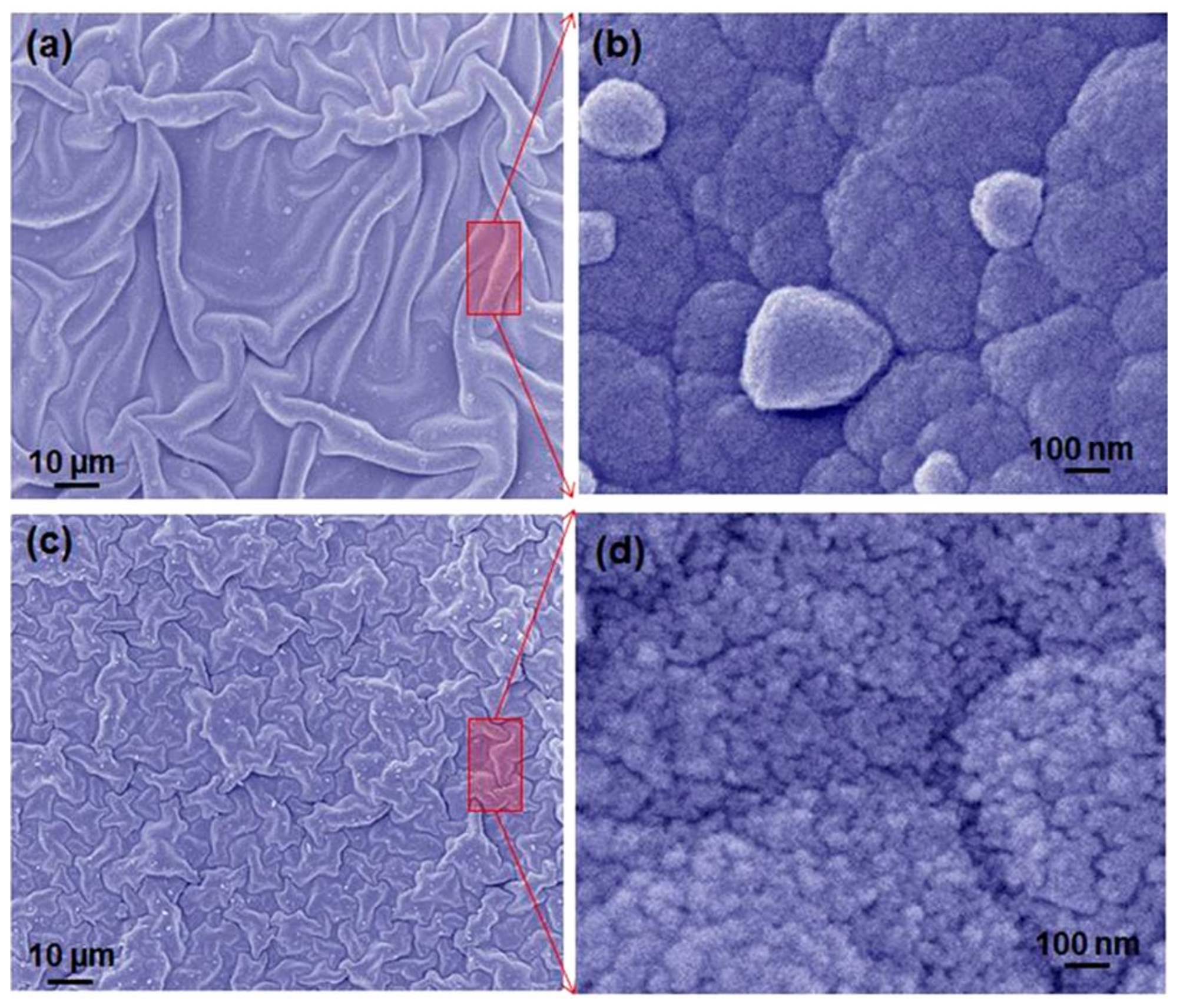
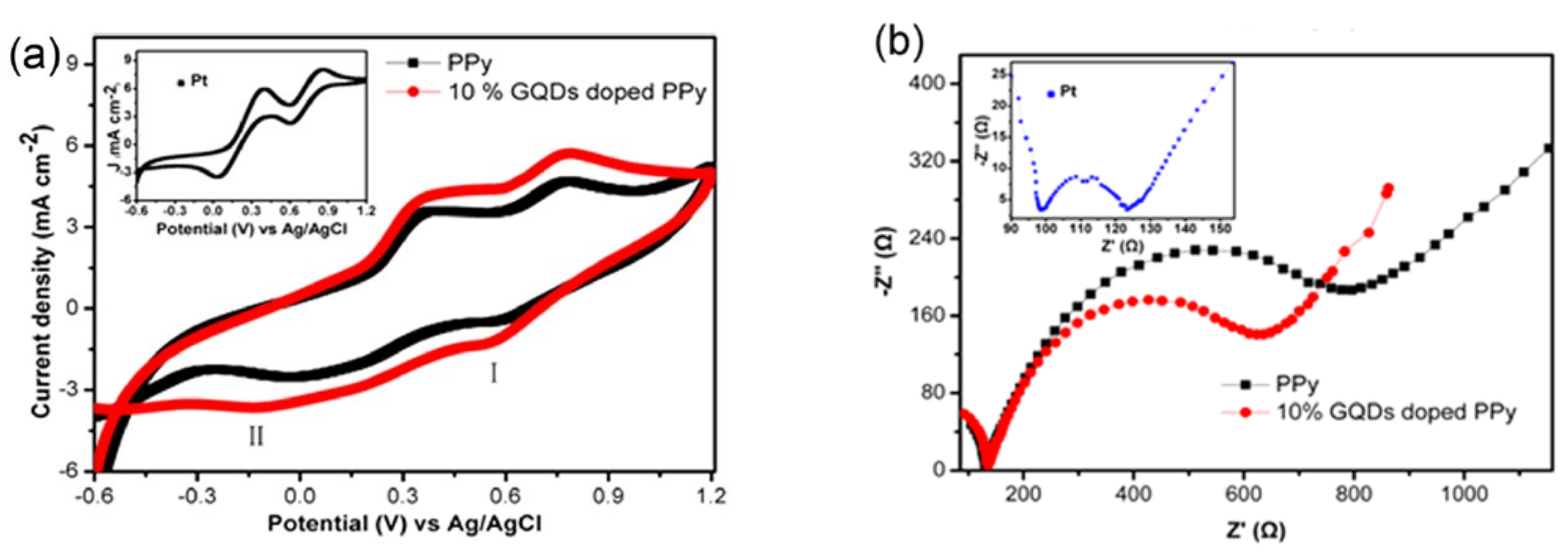
Contrary to carbon nanotubes and graphene, GQDs exhibit much smaller sizes while retaining their graphitic nature. In Chen and his coworkers’ research [15], GQDs were prepared with a chemical oxidation approach and used to dope in polypyrrole (PPy) film through the electrochemical codeposition method. The transmission electron microscope (TEM) image in Figure 1a shows that the GQDs show quite a uniform size of around 10 nm. The atomic force microscope (AFM) image, along with the corresponding height profile (as shown in Figure 1b), revealed that the GQDs exhibited an average height of 0.8 nm, indicating the monolayer structure. The morphologies of GQD-doped PPy and bare PPy films are observed by scanning electron microscope (SEM), as shown in Figure 2. The GQD-doped PPy film exhibits a porous structure, while the plain PPy shows quite a dense structure. If there were more GQDs in the PPy film, the pertinent counter electrode would possess better electrode kinetics due to the increase of electrocatalytic actives. As shown in Figure 3a, the cyclic voltammetry (CV) curves demonstrate a typical pair of adsorption peaks (~0.4 V vs. Ag/AgCl) and a pair of I/I3 redox reactions at approximately −0.4 and 0.75 V, respectively, similarly to the previous report [16]. The more positive potential of the reduction peak and higher current density of the GQD-doped PPy electrode reveal that it performs a higher electrocatalytic activity and more reaction actives for the I3 ions reduction. Figure 3b shows the Nyquist plots of GQD-doped PPy and PPy electrodes, measured by electrochemical impedance spectroscopy (EIS). The semicircle diameter of GQD-doped PPy is smaller than that of PPy, indicating that the charge-transfer resistance (Rct) of GQD-doped PPy is lower than that of PPy. These results imply that GQDs can improve the charge transfer rate in the cathodic reaction process.
DSSC with 10% GQD-doped PPy CEs achieves the highest power conversion efficiency (PCE) at 5.27%, which is around 20% higher than that of DSSC with bare PPy (4.46%) and is comparable to that of DSSC with platinum (Pt) (see Table 1). The GQD-doped PPy CE provides a promising candidate to replace Pt as a cheap CE for high-performance DSSC.

2.2. Graphene Quantum Dot-Decorated Strontium Ruthenate (SrRuO3) Mesoporous Film

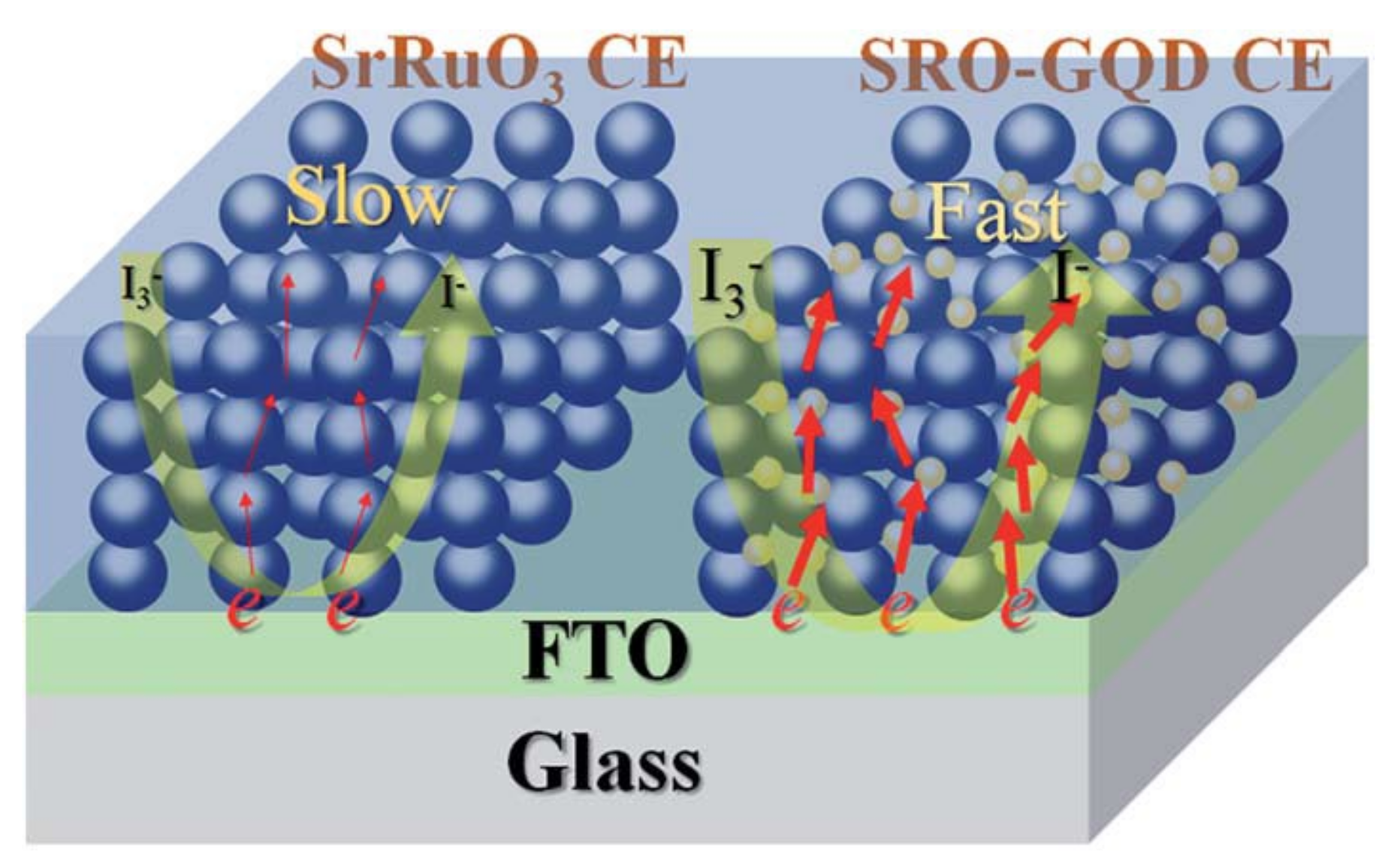
Liu et al. [17] found that, via a dipping technique, the combination of strontium ruthenate (SrRuO3, SRO) nanoparticles and GQDs yields a compelling advantage in terms of improving the conductivity and the catalytic activity (Figure 4) [17]. GQDs with good conductivity are responsible for connecting SrRuO3 nanoparticles and promoting the formation of a conductive network for the SRO–GQD CEs, which show a resistivity of 4.5 × 10⁻²–5.9 × 10⁻² Ω cm via a four-probe measurement. The synergic effect of SrRuO3 and GQDs provides multiple benefits in driving ion spread and collecting electrons from the external circuit, as well as in accelerating electron transfer to catalytic sites, thus achieving a high electrocatalytic capability towards the I/I3 redox reaction. Consequently, this results in a great PCE of DSSC devices with SRO–GQD CEs (8.05%) (see Figure 5), which is much higher than for DSSCs with other kinds of GQD-based composite CEs in the literature [18].
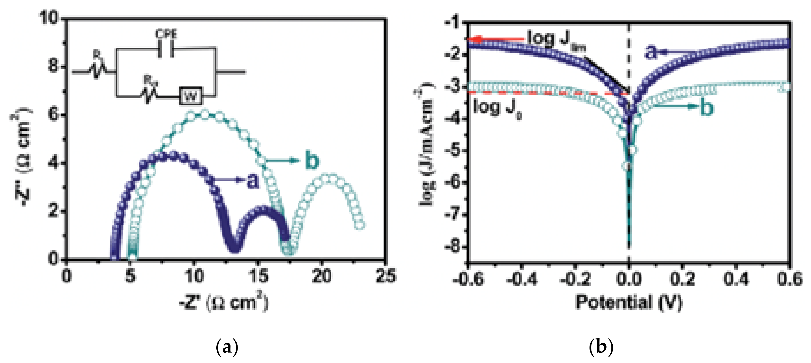
According to the Nyquist plots shown in Figure 6a, one can obviously see that the semicircle diameter of the SRO–GQD CE is smaller than that of the SrRuO3 CE, suggesting a lower Rct of SRO–GQD than that of SrRuO3. The Tafel polarization curves shown in Figure 5b characterize the catalytic abilities of SrRuO3 and SRO–GQD CEs towards the I/I3 redox reaction. The exchange current density (J0) and the limiting diffusion current density (Jlim) obtained from the Tafel curves are closely related to the catalytic activity of the CEs. Compared with SrRuO3, SRO–GQD possesses a higher J0 due to a larger slope for the anodic or cathodic branches, revealing a higher electrocatalytic activity on the I/I3 redox reaction, which is in good correlation with the trends derived from the CV and EIS analyses.

2.3. Graphene Dots (GDs)/poly(3,4-Ethylene Dioxythiophene):poly(4-Styrene Sulfonate) (PEDOT:PSS) Composite Film

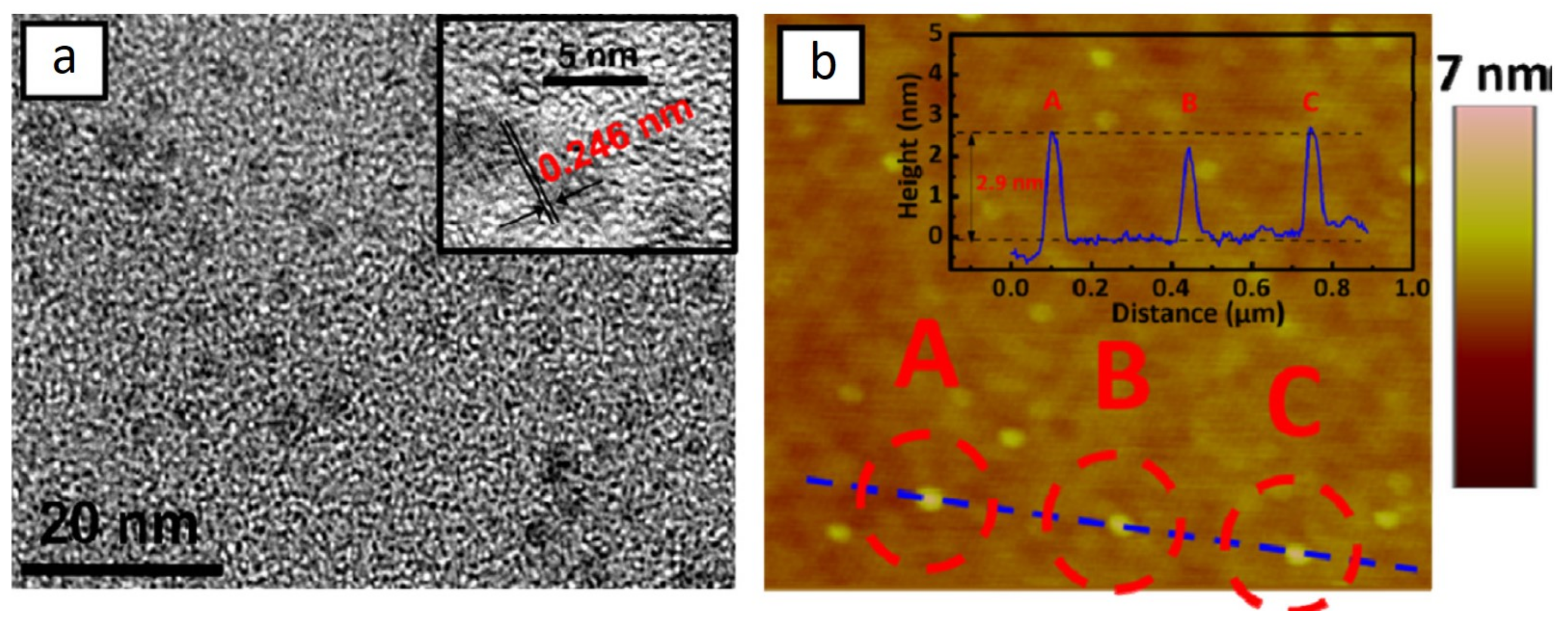
A water-dispersible conducting polymer, PEDOT:PSS, has attracted much attention as the catalytic CE of DSSCs, mainly due to its outstanding advantage of having aqueous solution processability [19]. However, pristine PEDOT:PSS films are limited by a low conductivity and poor electrocatalytic activity in the reduction of I3, due to the nonconductive counter anion of PSS, which blocks the electron transporting path inside the film. In recent research [20], the conductivity and catalytic surface areas could be improved by doping carbon materials, especially GDs with high active sites, into PEDOT:PSS films. Figure 7a shows the TEM image of the monodispersed GDs, which exhibit uniform diameters of 3.5 nm. As shown in the inset of Figure 7a, the high-resolution TEM (HRTEM) image indicates a high crystallinity of GQDs with a lattice parameter of 0.246 nm that corresponds to the (1120) lattice fringes of graphene. The AFM image of monodispersed GDs is shown in Figure 7b. The average height of these GDs is 2.90 nm, as shown in the inset of Figure 7b.
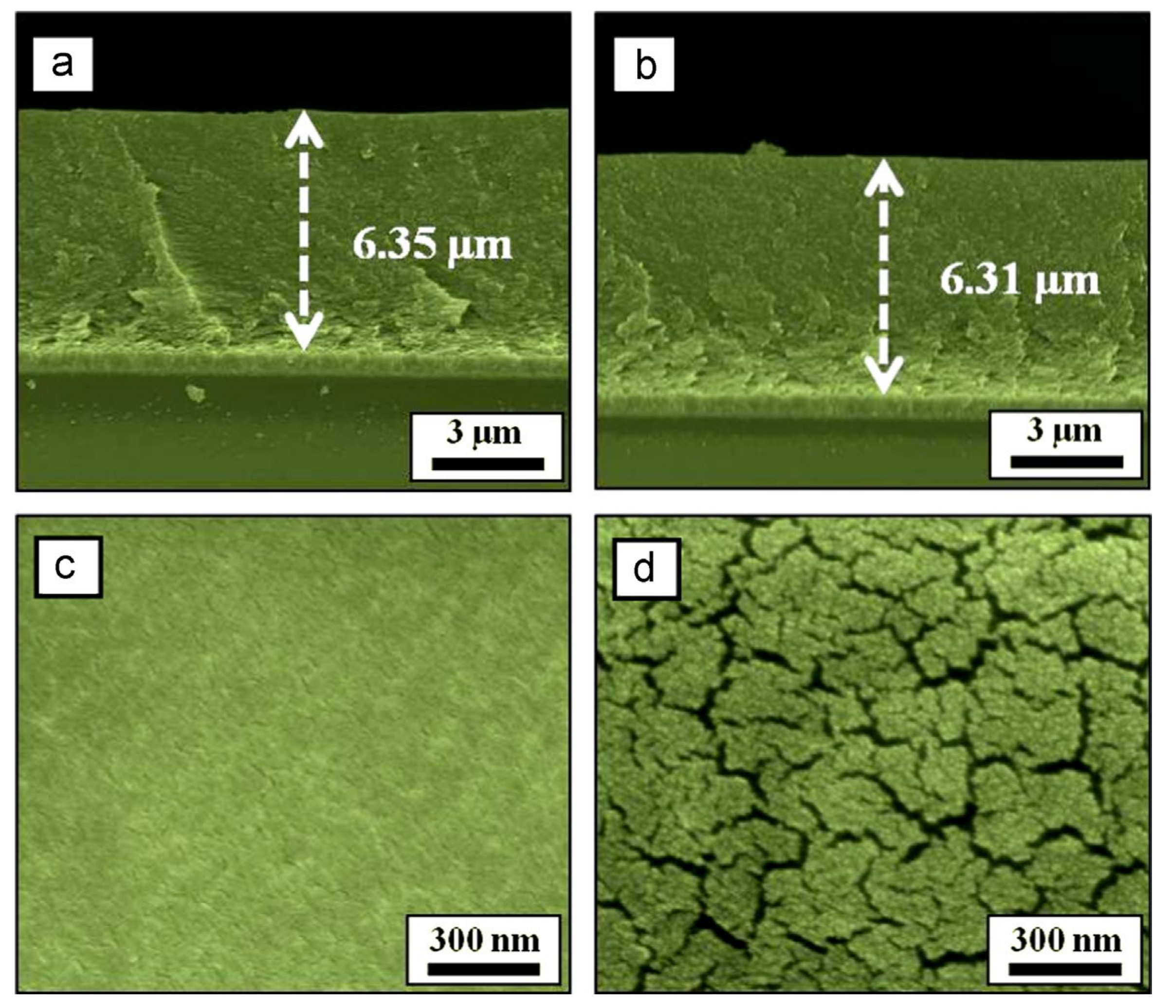
As shown in Figure 8, the thickness of PEDOT:PSS and GD-PEDOT:PSS films are almost similar (around 6.3 μm); the PEDOT:PSS film exhibits a flat and smooth morphology, while the GD-PEDOT:PSS film displays a rough morphology consisting of irregular island-like structures. The high superficial roughness is predicted to enhance the electrocatalytic activity for the I/I3 redox couple, as well as to reduce the Rct at the CE/electrolyte interface. Moreover, the sheet resistance of the GDs-PEDOT:PSS film (1.5   ×   10−4 Ω cm) was found to be lower when compared to that of the PEDOT:PSS film (9.6 × 10⁻⁴ Ω cm). We found that GD-PEDOT:PSS CEs possess a higher cathodic current density and smaller redox peaks separation (347 mV) (Figure 9a and Table 2), which can be attributed to its larger surface area and the faster charge transfer kinetics at the CE/electrolyte interface. The photocurrent density versus voltage (J–V) characteristics of the DSSCs with PEDOT:PSS CEs and GD-PEDOT:PSS CEs are shown in Figure 9b, and the corresponding photovoltaic parameters are listed in Table 3. The cell with GD-PEDOT:PSS CEs shows the best performance, with a cell efficiency of 7.36%, which is much higher than that of the cell with PEDOT:PSS CEs (5.14%) and close to that of the cell with sputtered Pt CEs (8.46%). Compared to the photocurrent density (JSC) of the DSSC with flat PEDOT:PSS films as CEs, the DSSC with GD-PEDOT:PSS CEs performs a high JSC, which is attributed to more electrocatalytically active sites on the rough surface of GD-PEDOT:PSS films for the reduction of triiodide ions. A faster diffusion of the redox couple is expected in the electrolyte of the DSSC with GD-PEDOT:PSS CEs due to the faster reduction of I3 ions at the CE of the cell, which in turn can lead to faster electron transfer kinetics and a higher fill factor (FF) for the cell (0.70), when compared to that of the cell with PEDOT:PSS CEs (0.60). The Rct property at the CE/electrolyte interface was performed by EIS. The symmetric sandwich-type cells with PEDOT:PSS and GD-PEDOT:PSS electrodes possess Rct values of 10.38 and 7.92 Ω cm2, respectively (Figure 9c). The results show that GD-PEDOT:PSS catalytic films can effectively catalyze the reduction of I3 ions to I ions due to low charge transfer resistances, leading to a high performance of the DSSC with GD–PEDOT:PSS CEs.
Furthermore, there are several studies that focus on MoS2 quantum dots (MSQDs) in relation to the hydrogen evolution reaction (HER) and oxygen evolution reaction (OER). Density functional theory studies show that MSQDs are reactive and that the vacancies at the edges can promote the reaction, which indicates that defects at the edges are efficient for the OER and HER. However, the synthesis of MSQDs is usually done in the presence of carbon solvents, which results in the formation of unavoidable carbon QDs (CQDs), which would interfere with the properties and performance of MSQDs. The report shows that applying the one-step methods can avoid the formation of unwanted carbon quantum dots (CQDs) and enhance the OER activity of MSQDs [21]. MSQD is also a good material for the HER reaction. The monolayer MSQDs exhibit superior HER catalytic activities with a low overpotential of approximately 120 mV and a relatively small Tafel slope of 69 mV dec−1. Both the unique structure and the large amounts of exposed active edge sites make monolayer MSQDs promising HER electrocatalysts [22].

3. One-Dimensional Materials for Hydrogen Evolution Reaction (HER)

3.1. One-Dimensional Nanowire

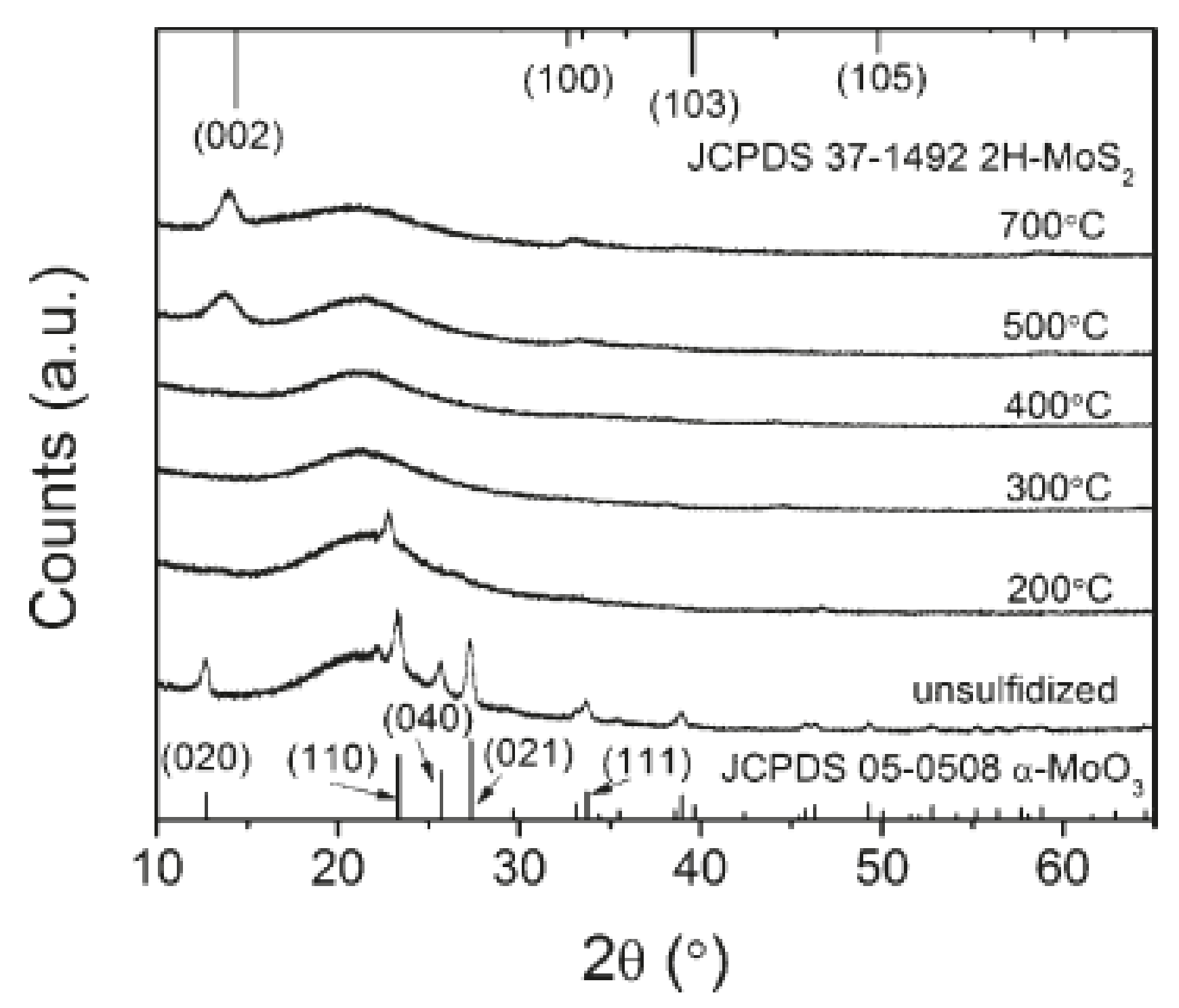
In 2011, Chen et al. [23] successfully synthesized vertically oriented core-shell molybdenum(VI) oxide-molybdenum disulfide (MoO3-MoS2) nanowires [23]. They used low-temperature sulfidization to obtain the best properties of each material. There are no apparent changes in the nanowire morphology before (Figure 10a) or after (Figure 10b) sulfidization at 200 °C. Some nanowires exhibit sharper tips and have a more grass-like morphology at 300 °C or higher sulfidization temperatures (Figure 10b–f). The X-ray diffraction (XRD) spectra shown in Figure 11 indicate that, when sulfidized at 300 °C and above, all peaks corresponding to the MoO3 disappear, which means a lack of long-range order of the phase. Combining a conductive core comprised of substoichiometric MoO3 with a conformal MoS2 shell, they have created a high-aspect ratio structure that can enhance charge transports over large distances with a high catalytic activity and stability in acidic solvents. Electrochemical measurements of the core-shell MoO3-MoS2 nanowires are shown in Figure 12. Apparently, sulfidization at 300 °C decreases the HER activity. However, the nanowires with sulfidization at 200 °C demonstrate a lower overpotential of approximately 150–200 mV. A Tafel plot was constructed to gain more insight into the activity of nanowires: the Tafel slope was 50–60 mV/decade near the onset of the current at 200 mV. Compared with other non-noble materials, the core-shell MoO3-MoS2 nanowire (denoted “MoS2” in Figure 12d) is highly active, especially at higher current densities (>10 mA cm−2).
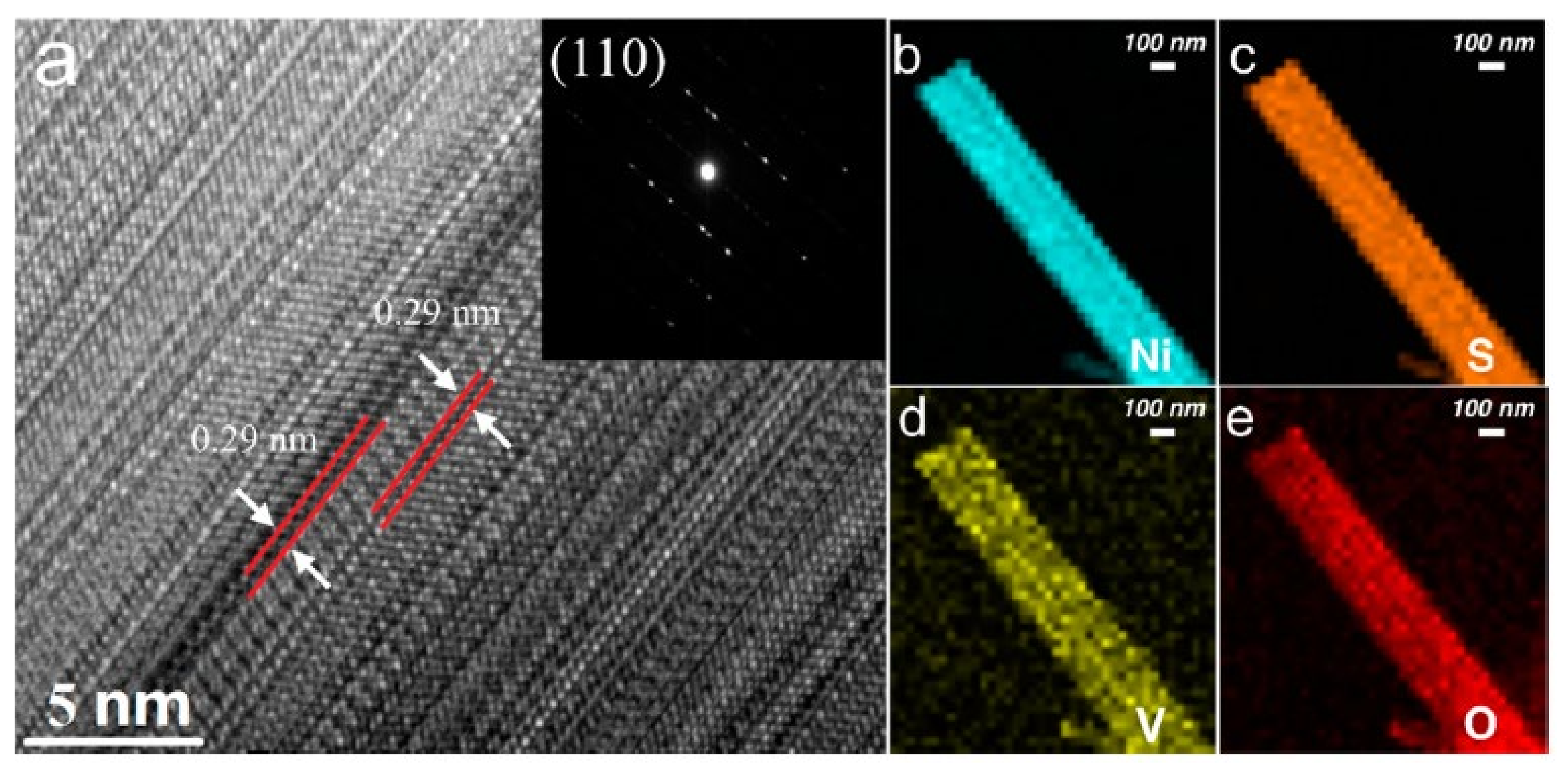
Furthermore, in 2017, Qu et al. [24] found that the vanadium (V)-doped nickel sulfide (Ni3S2) nanowire arrays exhibited an excellent electrocatalytic performance for HER [24]. As shown in the SEM and HRTEM images in Figure 13 and Figure 14, V-doped Ni3S2 nanowire (V-Ni3S2-NW) arrays grow uniformly on the nickel foam. This report also indicates that pure a Ni3S2 nanowire cannot be manufactured at 160 °C or lower temperatures without oxidizing the Ni foam or introducing copolymer into the solution [24].
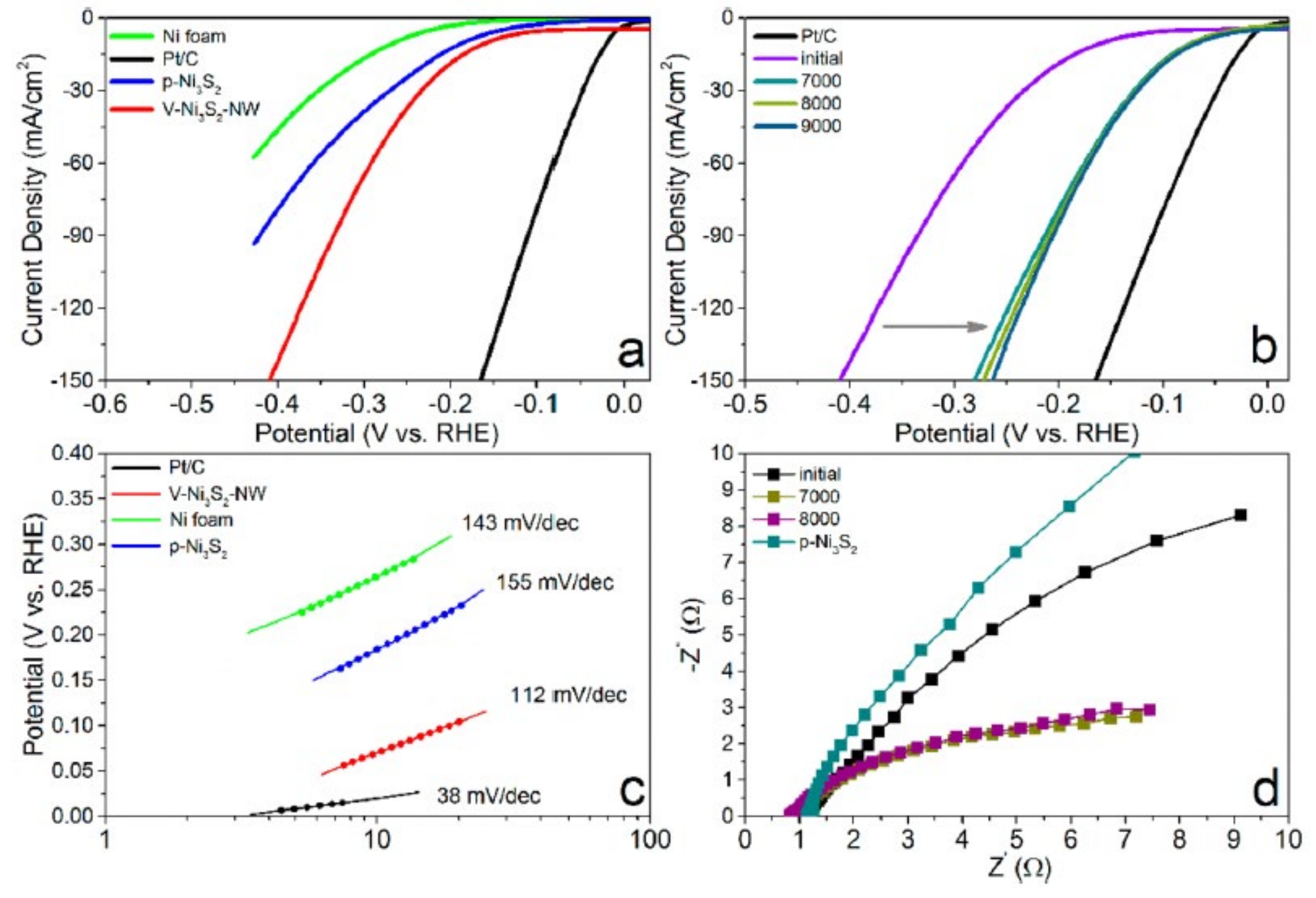
In the polarization curve (Figure 15a), V-Ni3S2-NWs demonstrate a lower overpotential (~203 mV) than the pure Ni and Ni3S2 nanoparticles (~232 mV) at a current density of 20 mA cm−2. It was also found that, after thousands of cycles under the same condition, V-Ni3S2-NWs enhance the performance remarkably and remain stabilized. Moreover, at a current density of 10 mA cm−2, its overpotential is reduced from 157 to 68 mV after 7000 cycles (Figure 15b), which is better than MoS2/Ni3S2 nanosheets (110 mV) [25] and MoOx/Ni3S2 (106 mV) grown on nickel foams under the same condition [26]. Compared with the Tafel slope of the pure Ni foam and pure Ni3S2 nanostructure (Figure 15c), V-Ni3S2-NW shows the smallest Tafel slope value (112 mV). Additionally, V-doped Ni3S2, in improving the free carrier density near the Fermi level, leads to an enhancement of the catalytic activity, which is also proven via first-principles calculations in this article [24].

3.2. One-Dimensional Nanotube

By optimizing the growth condition, Xu et al. [27] successfully synthesized ternary WS2(1-x)Se2x. nanotubes (NTs) and could systematically control the composition of S and Se on the carbon fibers [27]. In this report, they could also identify and compare the electrocatalytic activity of WS2, WSe2, and WS2(1-x)Se2x nanotubes, respectively. From the TEM image (Figure 16), the as-prepared WS2, WSe2 and WS2(1-x)Se2x exhibit multiwall nanotubes. In general, NTs display a full opening, but some WS2 NTs seem to be sealed when the growth is terminated. Besides, many previous reports have implied that the exposed edge sites and conductivity of TMCs are essential to an impressive HER performance [28,29,30]. The HRTEM images show the layer dislocations and defects (pointed out by red arrows) in the wall, as shown in Figure 16b,d; meanwhile, NTs demonstrate a large surface area because of their hollow structure.
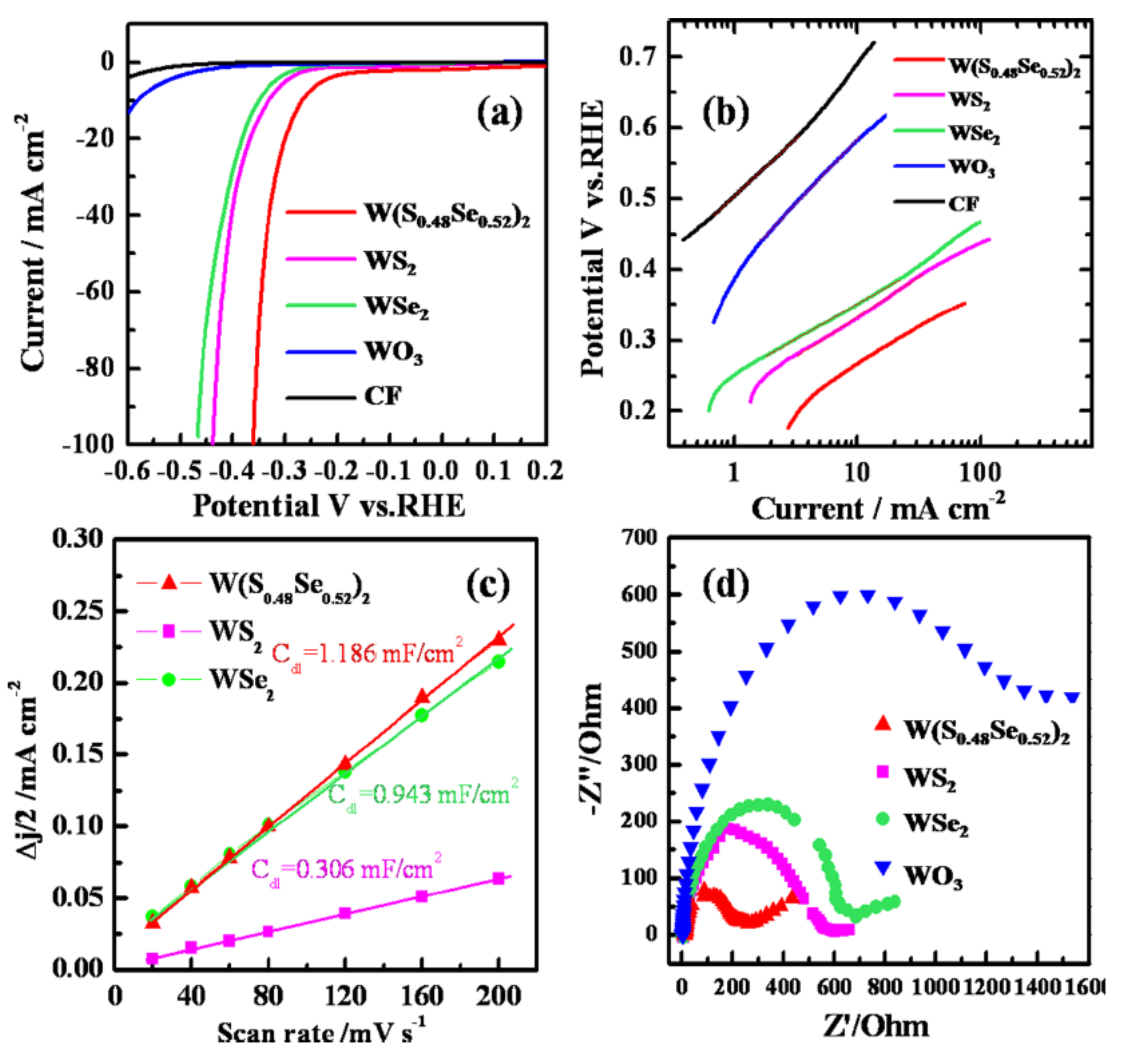
The electrocatalytic measurements show that the electrocatalytic properties of WSe2 and WS2 NTs are similar; the WS2(1-x)Se2x NTs (x = 0.52) demonstrate the best catalytic activity among all NT electrocatalysts (Figure 17a). According to the previous work, changing the geometry of the TX2-type inorganic nanotubes (T = Mo, W; X = S, Se, Te) can elongate the T-X bond lengths, which influences their electronic properties [31], and comprised of different elements can bring about the synergistic effect of rich active sites and a great conductivity in the electrocatalyst [32]. Thus, the ternary WS2(1-x)Se2x NTs process a higher number of active sites and a higher conductivity for the HER performance. This can also be confirmed by other measurements. A lower Tafel slope of ~105 mV/decade (Figure 17b), Rct of ~204 Ω cm2 (Figure 17d), higher exchange current density (0.029 mA cm−2), and large electrochemical double-layer cy (EDLC) (1.186 mF cm−2) (Figure 17c) demonstrate that WS2(1-x)Se2x NT is an excellent catalyst for HER.

3.3. One-Dimensional Nanoneedle

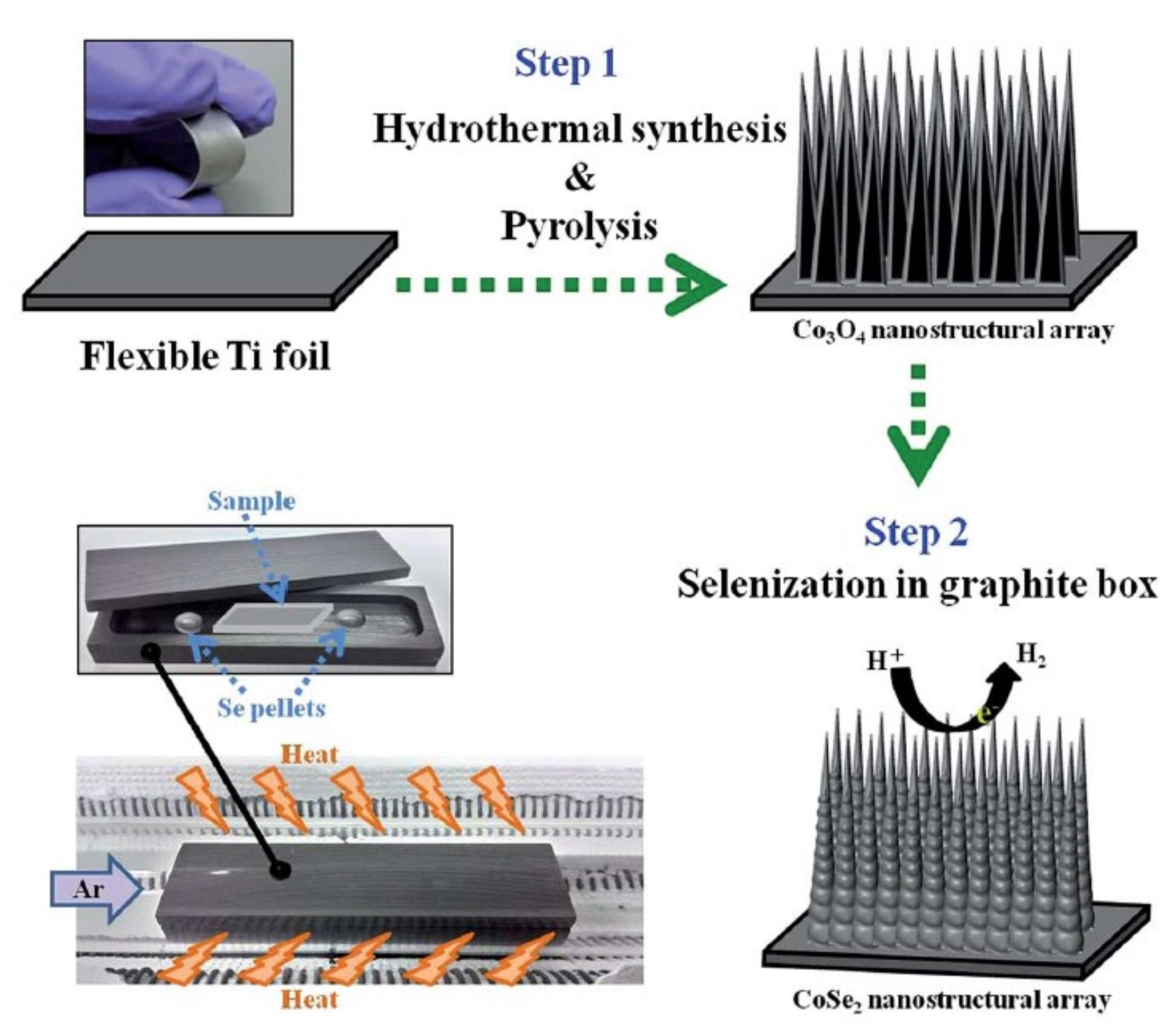
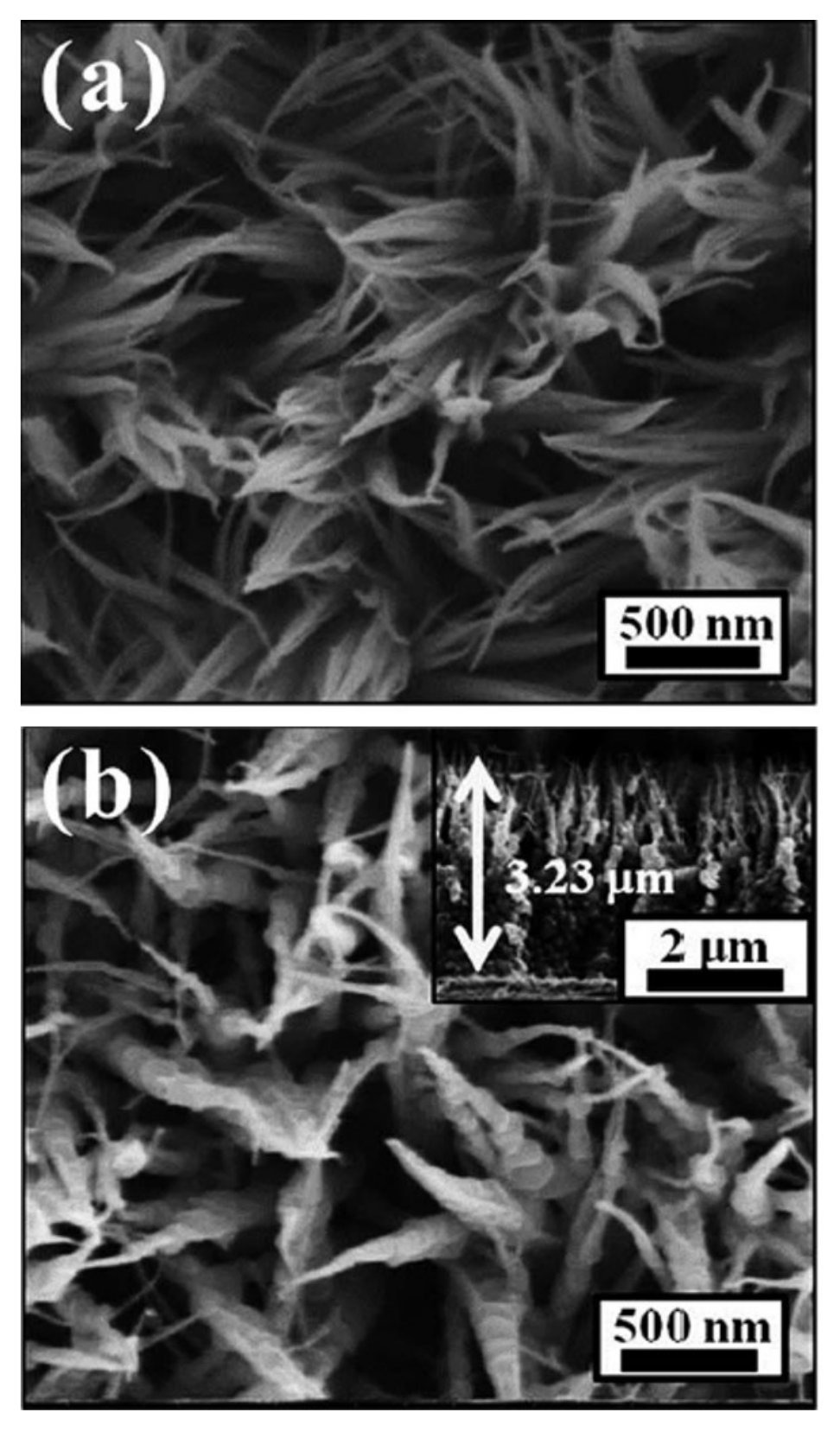
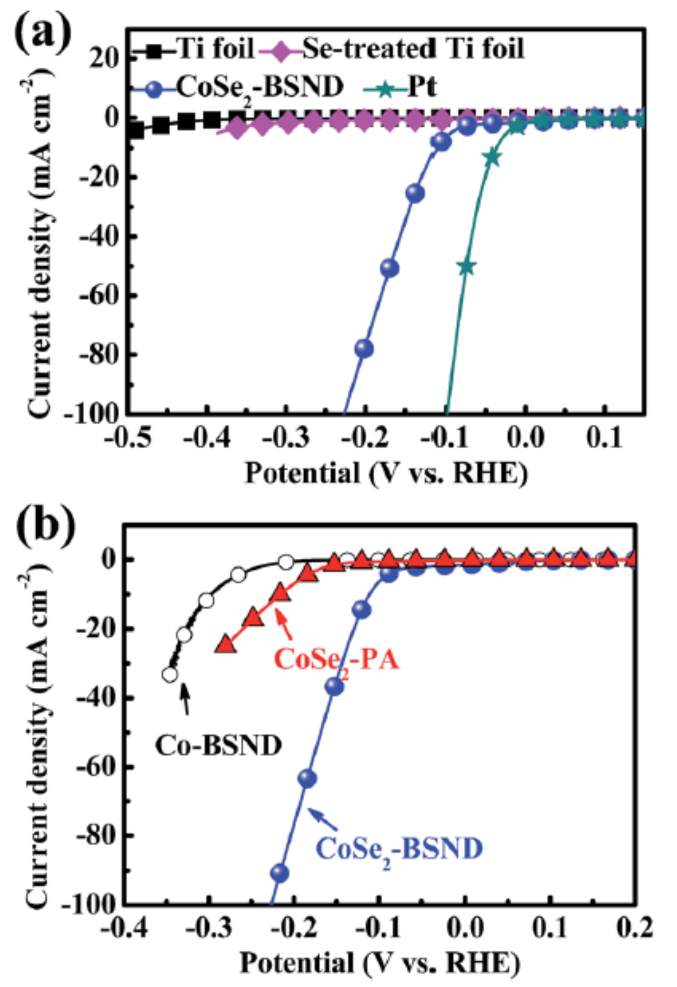
Lee et al. [33] synthesized the beaded stream-like CoSe2 nanoneedle array (CoSe2-BSND) directly formed on the flexible titanium foil by a two-step hydrothermal-selenization approach (Figure 18), which is the unique hierarchical structure shown in Figure 18 [33]. Through this architecture, CoSe2-BSND possesses highly accessible surface active sites, a strongly attractive force between water and the surface of nanoneedles, and it enhances charge transfer kinetics. The SEM images (Figure 19) show that the nanoneedle arrays maintain the morphologies before and after the selenization process.
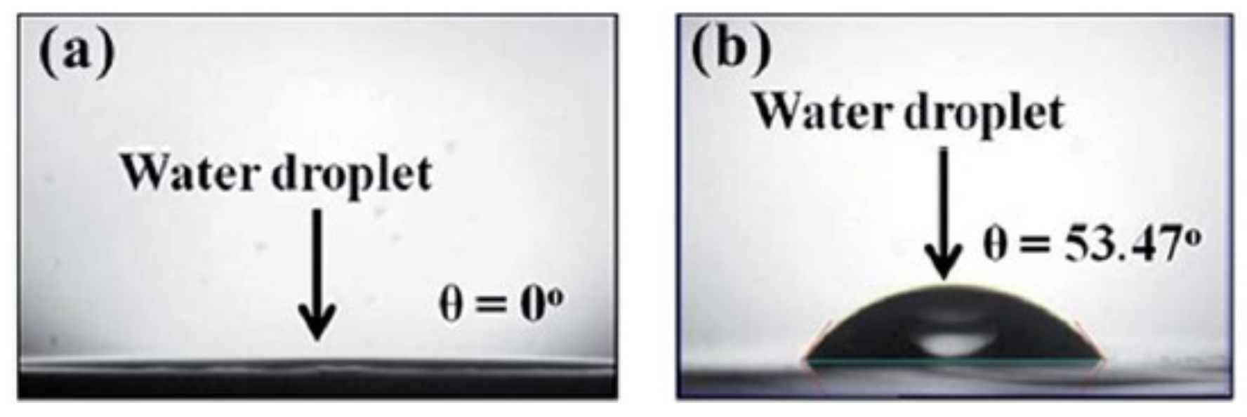
In Figure 20, compared with the Ti foil and Se-treated Ti foil, CoSe2-BSND demonstrates a better activity of HER at a current density of 20 mA cm−2. Moreover, according to the published reports related to TMC-based HER catalysts [34,35], i.e., electrocatalysis of the hydrogen evolution reaction by electrodeposited amorphous cobalt selenide films, the activity of CoSe2-BSND belongs to the top group of these catalysts under similar conditions (Table 4). For the Co-BSND, the Tafel slope is 77.5 mV/decade; by contrast, CoSe2-BSND possesses a lower Tafel slope (48.5 mV/decade), which means a faster discharge of protons (Figure 21). Therefore, the presence of selenium in the Co lattice prefers proton adsorption kinetics. In Figure 22, we can see that the surface contact angle of CoSe2-BSND is close to zero, which indicates an increase in the effective electrode surface area and a decrease in the mass transport resistance. Likewise, a high exchange current density and low charge-transfer resistance confirm that CoSe2-BSND is an outstanding HER catalyst.

4. Two-/Three-Dimensional Materials for the Counter Electrode of Dye-Sensitized Solar Cells

4.1. Molybdenum Disulfide (MoS2)

Recently, 2D TMDCs have attracted huge attention due to their excellent physical and chemical properties. Among them, molybdenum disulfide (MoS2), a layered material with a thickness of only three atoms, is one of the most typical TMDC materials. Bulky MoS2 is a semiconductor with an indirect energy gap of 1.29 eV, while monolayer MoS2 (which can be stripped from bulk MoS2 or prepared by chemical vapor deposition) is a semiconductor material with a direct energy gap of 1.9 eV [36].

4.2. MoS2/Graphene Composite

Yue et al. [37] used a MoS2/graphene flake composite as a Pt-free CE to catalyze the iodine/iodide (I/I3) redox couple in DSSCs [37]. The SEM images of the MoS2, graphene, and MoS2/graphene composite are shown in Figure 23. In the CV results, the cathodic current density of the MoS2/graphene composite CE for the I3 reduction was higher than that of MoS2, graphene, and Pt CEs. The J–V curves of DSSCs with MoS2/graphene as CEs at different thicknesses were investigated and compared with that of the DSSCs using conventional Pt CEs (Figure 24). The performances of the DSSCs were affected by the MoS2/graphene layer number (Figure 24a,d). The Jsc and open-circuit voltage (Voc) increased when the layer number increased from monolayer to trilayer. From 0.5 wt% (weight percent) to 1.5 wt%, the graphene content also reflected a decrease in Rct for MoS2/graphene CEs (Figure 24d). The PCE of the DSSCs with MoS2/graphene composite CEs with 1.5 wt% graphene showed an impressive efficiency of 5.98%, which was very close to the PCE of DSSCs with Pt CEs (6.23%) (Figure 24b). The results proved that the MoS2/graphene composite is a low-cost alternative to the Pt CE.

4.3. MoS2/N-Doped Graphene Composite

Fan et al. [38] successfully synthesized nitrogen-doped graphene (NGr) with a MoS2 (NM-8) composite film prepared by the drop-coating method as a CE for DSSCs (Figure 25) [38]. The electrocatalytic activity of NM-8 composite films for the reduction of triiodide (I3) was much higher than that of the pristine N-graphene and MoS2 thin films because of the lower Rct at the CE/electrolyte interface (Table 5). With the introduction of NGr, there is an increase in the electrical conductivity of the composite film. Here, the N atom attracts the electron clouds from nearby C atoms because of the difference in the electronegativity between C and N, promoting the electron transfer and hence forming an active site [39]. Furthermore, the electrocatalytic activity of the composite film increases due to the addition of MoS2, which provides more active sites on its edges. The performance of DSSCs with NM-8 composite films as CEs displays a promising efficiency of 7.82%, which is just slightly lower than that of DSSCs with the Pt CE (8.25%).

4.4. Nickel Disulfide (NiS2)

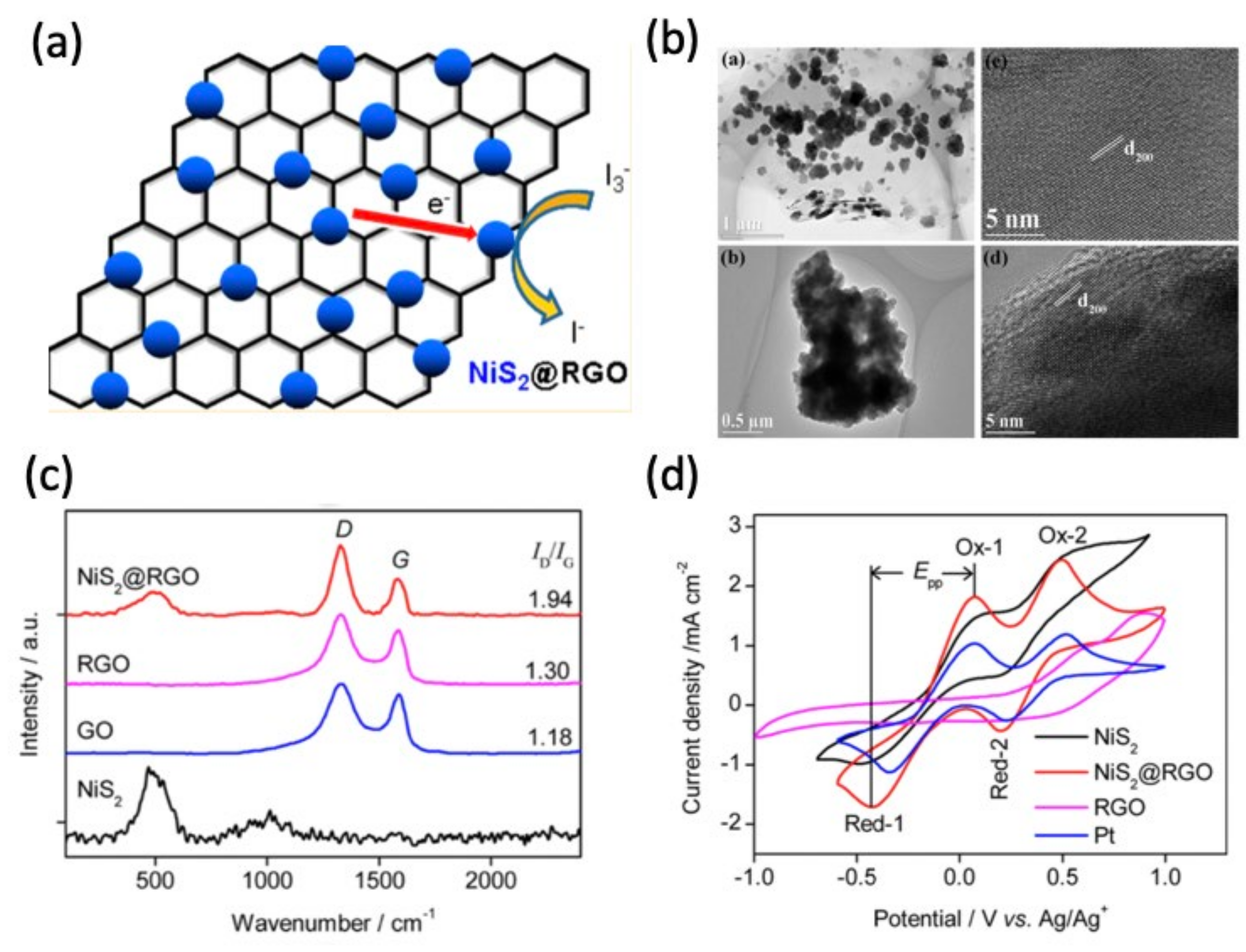
Nickel disulfide (NiS2) can be synthesized by different methods, such as vapor phase reaction, hydrothermally, ultrasonic irradiation and solvothermal [40]. Nickel disulfide (NiS2) is a semiconductor with a pyrite structure, which exhibits great electrical, optical, and catalytic properties in many different morphologies [41,42]. Li et al. [43]. synthesized the composite of NiS2 nanoparticles and reduced graphene oxide (NiS2@RGO) via a hydrothermal reaction (Figure 26a) [43]. GO serves as a substrate for the nucleation of NiS2 nanoparticles, which results in well-dispersed NiS2 nanoparticles on a graphene oxide sheet (Figure 26b). The stretching vibration peak of NiS2 at 480 cm−1 can be observed in the samples of NiS2 and NiS2@RGO (Figure 26c). Judging by the higher reduction current and smaller redox peak potential separation, the catalytic activity of NiS2@RGO shows a superior performance when compared to that of NiS2- and RGO-only electrodes (Figure 26d). The DSSCs with the NiS2@RGO CE have the highest PCE at 8.55%, which is ascribed to a low Rct (Table 6). On the other hand, recently, the group-10 noble TMDCs have been reintroduced as new 2D materials, such as MX2, where M is a noble metal (Pd or Pt) and X is a chalcogenide element (S, Se, and Te). They display many attractive properties, including a widely tunable bandgap and excellent catalytic ability [44,45].

4.5. Tungsten Diselenide (WSe2)

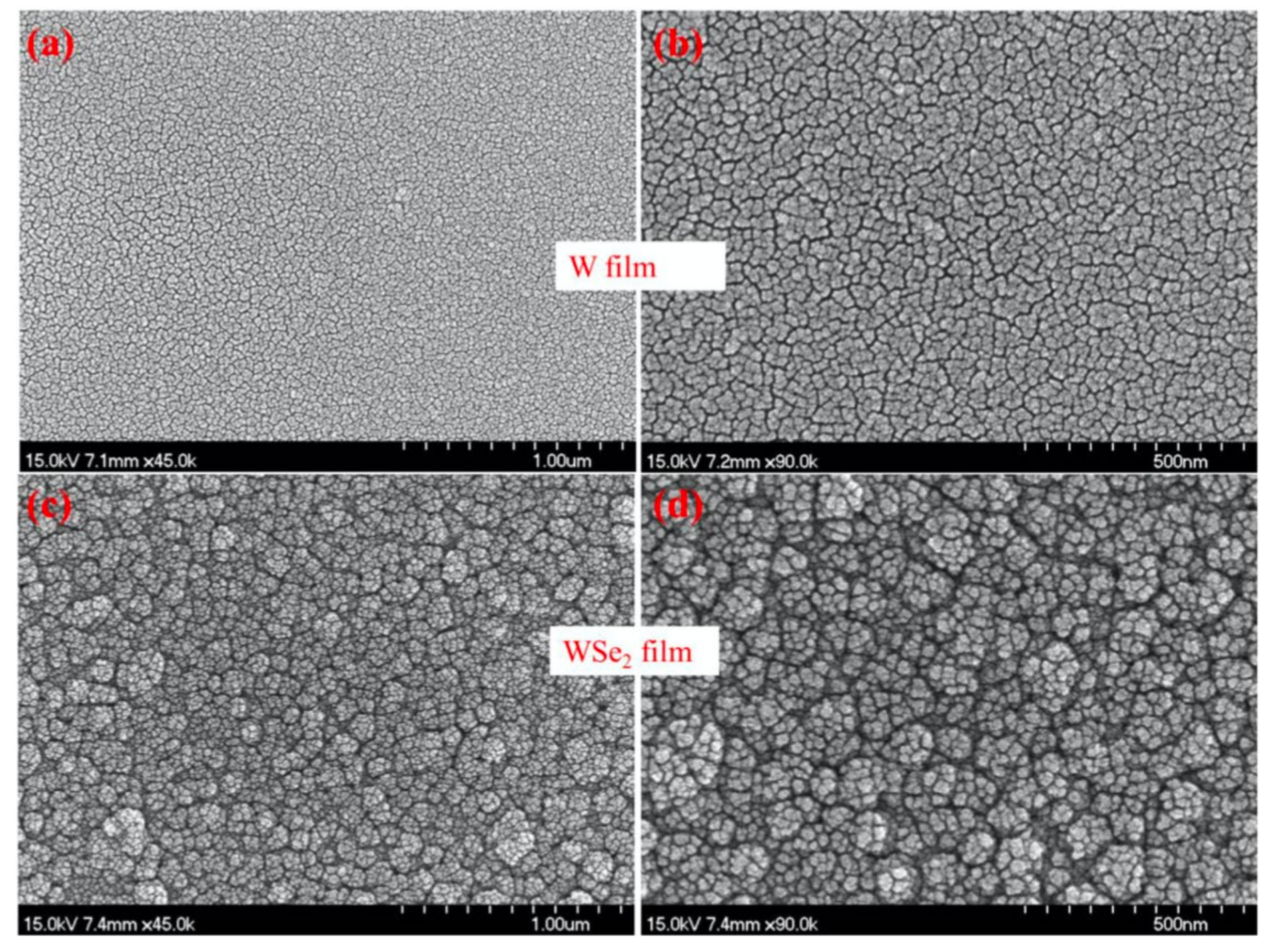
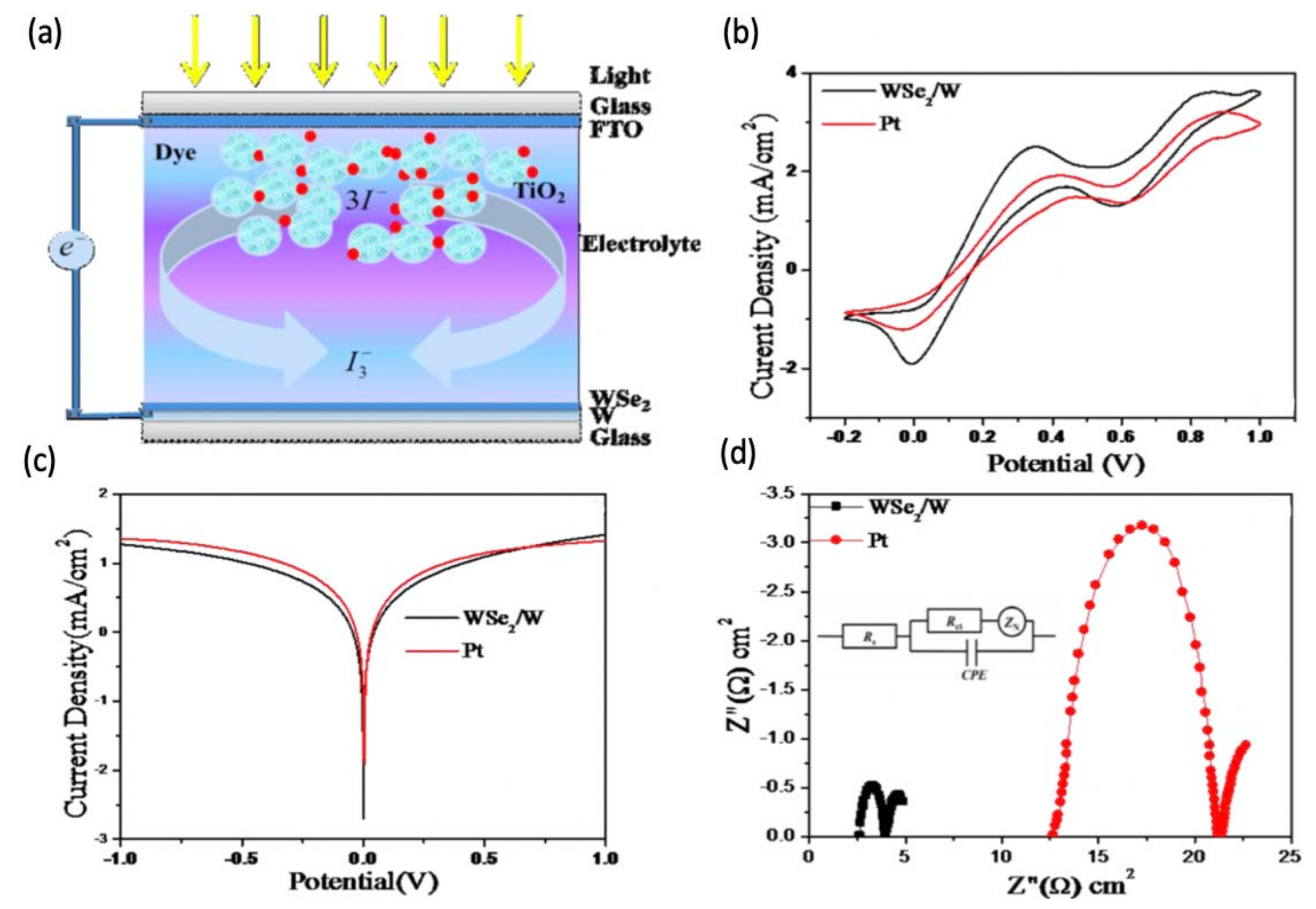
Hussain et al. [46] prepared WSe2/W by sputtering the W metal and then conducting a selenization annealing (Figure 27 and Figure 28) [46]. In Figure 29b, WSe2/W has a smaller cathodic peak potential and a larger current density, which indicates its lower overpotential, better electrocatalytic capability, and faster reaction speed for I3 reduction (Figure 29b). The abovementioned can be ascribed to the low overall cell resistance. The slopes of the anodic or cathodic part of WSe2/W are higher than those of Pt, which indicates a higher exchange current density on the electrode (Figure 29c). The EIS results show that the sheet resistance (2.64 Ω cm2) and Rct (1.38 Ω cm2) of the WSe2/W CE are smaller than those of Pt/FTO (12.72 Ω cm2 for the sheet resistance and 8.66 Ω cm2 for the Rct) (Figure 29d). The PCE of DSSCs with WSe2/W as CEs (8.22%) showed a better performance than that of DSSCs that were based on Pt CEs (8.20%).

4.6. Nitrogen-Doped Graphene Hollow Nanoballs (N-GHBs)

With its excellent electrical conductivity, high carrier mobility, mechanical strength, and chemical stability, graphene has become one of the potential noble-metal-free CEs in DSSCs [39]. However, the basal plane of graphene is smooth and inert, which is not active for catalytic reactions. In our work [5], We synthesized nitrogen-doped graphene with melamine as nitrogen source via a chemical vapor deposition (CVD) reaction (Figure 30a). Highly-curved GHBs with a 3D hollow nanoball structure can prevent self-assembly restacking in graphene and can provide high surface areas for electrocatalytic reactions. The heteroatomic incorporation enhances the catalytic activities and the electron transfer from N-doped active sites to the adsorbed I3 in the redox reaction of the electrolyte (Figure 30b,c). It was found that the contents of pyridinic N and quaternary N in N-GHBs/CC CEs play a crucial role in the catalytic activity of DSSCs. With a clear understanding of the role of different N-doped states in graphene, people can easily develop a gadget to design highly efficient electrocatalysts for DSSCs. Finally, the photovoltaic performance of the as-prepared N-GHBs with an N-doping content of 12.10% reached 7.53% because of the high specific surface area and the decrease of the Rct, which made it very close to that (7.70%) of the standard sputtered Pt CEs (Figure 31).

5. Conclusions

In this short review, we focused on the most recent progress related to low-dimensional electrocatalysts for electrochemical energy applications. Although Pt is a promising electrocatalyst for hydrogen evolution reactions and triiodide reduction reactions in DSSCs, its precious cost and poor stability reveal the difficulty of using it for practical applications. The development of an alternative to the Pt electrode with a high electrocatalytic activity and good stability is in high demand. GQDs with a good conductivity and high electrocatalytic activity on their edges have been shown to be good candidates as CEs for the triiodide reduction in DSSCs. By incorporating GQDs, the sheet resistance of CEs and the charge transfer resistance at the CE/electrolyte interface can be improved. Moreover, the use of 1D materials such as nanowires, nanotubes, and nanoneedles with fast charge transporting properties is attractive to energy conversion applications. Some reports have revealed that 1D nanostructures can change the hydrophilicity of the material surface and that the robust nanostructures can improve the stability of the hydrogen evolution reaction. Last but not least, 2D TMDCs with a low cost, earth abundance, high activity, and great stability have attracted much attention in recent years. 2D TMDCs have been investigated as potential materials to replace Pt as electrocatalysts. Studies have shown that 2D materials, such as MoS2, WSe2, etc., show an electrocatalytic activity that is comparable to that of a standard Pt electrode. For the future development of low-dimensional electrocatalysts with a superior electrocatalytic performance, we may try to synthesize a hierarchically composite matrix consisting of QD, 1D, and 2D nanostructures. Here, the vertically-aligned 1D electrocatalyst arrays can first be constructed on the electrode substrate, and then the leaf-like 2D electrocatalysts are directly synthesized on the side-wall of the vertically-aligned 1D electrocatalyst; finally, QD electrocatalysts are further used to decorate the basal plane of the 2D electrocatalysts. This design concept aims to solve the general challenges of using the abovementioned low-dimensional electrocatalysts alone, e.g., the aggregation and non-directional charge transport route of QD electrocatalysts; the poor activity on the basal plane of the 2D electrocatalysts and their restacking; and the lower surface area of the vertically-aligned 1D electrocatalyst as compared to QDs within a fixed film thickness. Accordingly, the as-designed composite matrix is expected to achieve a much higher electrocatalytic performance.

Author Contributions

Conceptualization and organization, C.-P.L. and C.-A.T.; Writing—Original draft, H.-Y.C., Y.-H.X. and L.-J.C. All authors have read and agreed to the published version of the manuscript.

Funding

This research received funding from Ministry of Science and Technology (MOST) of Taiwan.

Acknowledgments

This work was supported by the Ministry of Science and Technology (MOST) of Taiwan, under grant numbers 107-2113-M-845-001-MY3.

Conflicts of Interest

The authors declare no conflict of interest.

References

  1. Mas-Ballesté, R.; Gómez-Navarro, C.; Gomez-Herrero, J.; Zamora, F. 2D materials: To graphene and beyond. Nanoscale 2011, 3, 20–30. [Google Scholar] [CrossRef]
  2. Syama, S.; Mohanan, P.V. Comprehensive Application of Graphene: Emphasis on Biomedical Concerns; Springer: Berlin/Heidelberg, Germany, 2019; Volume 11. [Google Scholar]
  3. Wang, C.C.; Lu, S.Y. Carbon black-derived graphene quantum dots composited with carbon aerogel as a highly efficient and stable reduction catalyst for the iodide/tri-iodide couple. Nanoscale 2015, 7, 1209–1215. [Google Scholar] [CrossRef] [PubMed]
  4. Maity, N.; Kuila, A.; Das, S.; Mandal, D.; Shit, A.; Nandi, A.K. Optoelectronic and photovoltaic properties of graphene quantum dot–polyaniline nanostructures. J. Mater. Chem. A 2015, 3, 20736–20748. [Google Scholar] [CrossRef]
  5. Tseng, C.A.; Lee, C.P.; Huang, Y.J.; Pang, H.W.; Ho, K.C.; Chen, Y.T. One-step synthesis of graphene hollow nanoballs with various nitrogen-doped states for electrocatalysis in dye-sensitized solar cells. Mater. Today Energy 2018, 8, 15–21. [Google Scholar] [CrossRef]
  6. Nethravathi, C.; Jeffery, A.A.; Rajamathi, M.; Kawamoto, N.; Tenne, R.; Golberg, D.; Bando, Y. Chemical Unzipping of WS2 Nanotubes. ACS Nano 2013, 7, 7311–7317. [Google Scholar] [CrossRef]
  7. Ghorbani-Asl, M.; Zibouche, N.; Wahiduzzaman, M.; Oliveira, A.F.; Kuc, A.; Heine, T. Electromechanics in MoS2 and WS2: Nanotubes vs. monolayers. Sci. Rep. 2013, 3, 2961. [Google Scholar] [CrossRef] [Green Version]
  8. Levi, R.; Bitton, O.; Leitus, G.; Tenne, R.; Joselevich, E. Field-Effect Transistors Based on WS2 Nanotubes with High Current-Carrying Capacity. Nano Lett. 2013, 13, 3736–3741. [Google Scholar] [CrossRef]
  9. Chen, Z.; Duan, X.; Wei, W.; Wang, S.; Ni, B.J. Recent advances in transition metal-based electrocatalysts for alkaline hydrogen evolution. J. Mater. Chem. A 2019, 7, 14971–15005. [Google Scholar] [CrossRef]
  10. Kong, D.; Cha, J.J.; Wang, H.; Lee, H.R.; Cui, Y. First-row transition metal dichalcogenide catalysts for hydrogen evolution reaction. Energy Environ. Sci. 2013, 6, 3553–3558. [Google Scholar] [CrossRef]
  11. Seh, Z.W.; Kibsgaard, J.; Dickens, C.F.; Chorkendorff, I.; Nørskov, J.K.; Jaramillo, T.F. Combining theory and experiment in electrocatalysis: Insights into materials design. Science 2017, 355, 4998. [Google Scholar] [CrossRef] [Green Version]
  12. Sun, Y.; Wang, D.; Shuai, Z. Indirect-to-Direct Band Gap Crossover in Few-Layer Transition Metal Dichalcogenides: A Theoretical Prediction. J. Phys. Chem. C 2016, 120, 21866–21870. [Google Scholar] [CrossRef]
  13. Li, C.; Cao, Q.; Wang, F.; Xiao, Y.; Li, Y.; Delaunay, J.J.; Zhu, H. Engineering graphene and TMDs based van der Waals heterostructures for photovoltaic and photoelectrochemical solar energy conversion. Chem. Soc. Rev. 2018, 47, 4981–5037. [Google Scholar] [CrossRef] [PubMed]
  14. Choi, W.; Choudhary, N.; Han, G.H.; Park, J.; Akinwande, D.; Lee, Y.H. Recent development of two-dimensional transition metal dichalcogenides and their applications. Mater. Today 2017, 20, 116–130. [Google Scholar] [CrossRef]
  15. Chen, L.; Guo, C.; Zhang, Q.; Lei, Y.; Xie, J.; Ee, S.; Guai, G.; Song, Q.; Li, C.M. Graphene Quantum-Dot-Doped Polypyrrole Counter Electrode for High-Performance Dye-Sensitized Solar Cells. ACS Appl. Mater. Interfaces 2013, 5, 2047–2052. [Google Scholar] [CrossRef]
  16. Saranya, K.; Sivasankar, N.; Subramania, A. Microwave-assisted exfoliation method to develop platinum-decorated graphene nanosheets as a low cost counter electrode for dye-sensitized solar cells. RSC Adv. 2014, 4, 36226–36233. [Google Scholar] [CrossRef]
  17. Liu, T.; Yu, K.; Gao, L.; Chen, H.; Wang, N.; Hao, L.; Li, T.; He, H.; Guo, Z. A graphene quantum dot decorated SrRuO3mesoporous film as an efficient counter electrode for high-performance dye-sensitized solar cells. J. Mater. Chem. A 2017, 5, 17848–17855. [Google Scholar] [CrossRef]
  18. Gupta, V.; Chaudhary, N.; Srivastava, R.; Sharma, G.D.; Bhardwaj, R.; Chand, S. Luminscent Graphene Quantum Dots for Organic Photovoltaic Devices. J. Am. Chem. Soc. 2011, 133, 9960–9963. [Google Scholar] [CrossRef]
  19. Yue, G.; Wu, J.; Xiao, Y.; Lin, J.; Huang, M. Low cost poly(3,4-ethylenedioxythiophene): Polystyrenesulfonate/carbon black counter electrode for dye-sensitized solar cells. Electrochim. Acta 2012, 67, 113–118. [Google Scholar] [CrossRef]
  20. Lee, C.P.; Lin, C.A.; Wei, T.C.; Tsai, M.L.; Meng, Y.; Li, C.T.; Ho, K.C.; Wu, C.I.; Lau, S.P.; He, J.H. Economical low-light photovoltaics by using the Pt-free dye-sensitized solar cell with graphene dot/PEDOT: PSS counter electrodes. Nano Energy 2015, 18, 109–117. [Google Scholar] [CrossRef]
  21. Mohanty, B.; Ghorbani-Asl, M.; Kretschmer, S.; Ghosh, A.; Guha, P.; Panda, S.K.; Jena, B.; Krasheninnikov, A.V.; Jena, B.K. MoS2 Quantum Dots as Efficient Catalyst Materials for the Oxygen Evolution Reaction. ACS Catal. 2018, 8, 1683–1689. [Google Scholar] [CrossRef]
  22. Qiao, W.; Yan, S.; Song, X.; Zhang, X.; Sun, Y.; Chen, X.; Zhong, W.; Du, Y. Monolayer MoS2 quantum dots as catalysts for efficient hydrogen evolution. RSC Adv. 2015, 5, 97696–97701. [Google Scholar] [CrossRef]
  23. Chen, Z.; Cummins, D.; Reinecke, B.N.; Clark, E.L.; Sunkara, M.K.; Jaramillo, T.F. Core–shell MoO3–MoS2 Nanowires for Hydrogen Evolution: A Functional Design for Electrocatalytic Materials. Nano Lett. 2011, 11, 4168–4175. [Google Scholar] [CrossRef] [PubMed]
  24. Qu, Y.; Yang, M.; Chai, J.; Tang, Z.; Shao, M.; Kwok, C.T.; Yang, M.; Wang, Z.; Chua, D.; Wang, S.; et al. Facile Synthesis of Vanadium-Doped Ni3S2 Nanowire Arrays as Active Electrocatalyst for Hydrogen. ACS Appl. Mater. Interfaces 2017, 9, 5959–5967. [Google Scholar] [CrossRef]
  25. Zhang, J.; Wang, T.; Pohl, D.; Rellinghaus, B.; Dong, R.; Liu, S.; Zhuang, X.D.; Feng, X. Interface Engineering of MoS2/Ni3S2 Heterostructures for Highly Enhanced Electrochemical Overall-Water-Splitting Activity. Angew. Chem. Int. Ed. 2016, 55, 6702–6707. [Google Scholar] [CrossRef] [PubMed] [Green Version]
  26. Wu, Y.; Li, G.D.; Liu, Y.; Yang, L.; Lian, X.; Asefac, T.; Zou, X. Overall Water Splitting Catalyzed Efficiently by an Ultrathin Nanosheet-Built, Hollow Ni3S2-Based Electrocatalyst. Adv. Funct. Mater. 2016, 26, 4839–4847. [Google Scholar] [CrossRef]
  27. Xu, K.; Wang, F.; Wang, Z.; Zhan, X.; Wang, Q.; Cheng, Z.; Safdar, M.; He, J. Component-Controllable WS2(1–x)Se2x Nanotubes for Efficient Hydrogen Evolution Reaction. ACS Nano 2014, 8, 8468–8476. [Google Scholar] [CrossRef]
  28. Xie, J.; Zhang, H.; Li, S.; Wang, R.; Sun, X.; Zhou, M.; Zhou, J.; Lou, X.W.; Xie, Y. Defect-Rich MoS2 Ultrathin Nanosheets with Additional Active Edge Sites for Enhanced Electrocatalytic Hydrogen Evolution. Adv. Mater. 2013, 25, 5807–5813. [Google Scholar] [CrossRef]
  29. Gong, Y.; Liu, Z.; Lupini, A.R.; Shi, G.; Lin, J.; Najmaei, S.; Lin, Z.; Elías, A.L.; Berkdemir, A.; You, G.; et al. Band Gap Engineering and Layer-by-Layer Mapping of Selenium-Doped Molybdenum Disulfide. Nano Lett. 2013, 14, 442–449. [Google Scholar] [CrossRef]
  30. Phuruangrat, A.; Ham, D.J.; Hong, S.J.; Thongtem, S.; Lee, J.S. Synthesis of hexagonal WO3 nanowires by microwave-assisted hydrothermal method and their electrocatalytic activities for hydrogen evolution reaction. J. Mater. Chem. 2010, 20, 1683–1690. [Google Scholar] [CrossRef] [Green Version]
  31. Zibouche, N.; Ghorbani-Asl, M.; Heine, T.; Kuc, A. Electromechanical Properties of Small Transition-Metal Dichalcogenide Nanotubes. Inorganics 2014, 2, 155–167. [Google Scholar] [CrossRef]
  32. Xie, J.; Zhang, J.; Li, S.; Grote, F.; Zhang, X.; Zhang, H.; Wang, R.; Lei, Y.; Pan, B.C.; Xie, Y. Controllable Disorder Engineering in Oxygen-Incorporated MoS2 Ultrathin Nanosheets for Efficient Hydrogen Evolution. J. Am. Chem. Soc. 2013, 135, 17881–17888. [Google Scholar] [CrossRef] [PubMed]
  33. Lee, C.P.; Chen, W.F.; Billo, T.; Lin, Y.G.; Fu, F.Y.; Samireddi, S.; Lee, C.H.; Hwang, J.S.; Chen, L.C.; Chen, L.-C. Beaded stream-like CoSe2 nanoneedle array for efficient hydrogen evolution electrocatalysis. J. Mater. Chem. A 2016, 4, 4553–4561. [Google Scholar] [CrossRef]
  34. Kong, D.; Wang, H.; Lu, Z.; Cui, Y. CoSe2 Nanoparticles Grown on Carbon Fiber Paper: An Efficient and Stable Electrocatalyst for Hydrogen Evolution Reaction. J. Am. Chem. Soc. 2014, 136, 4897–4900. [Google Scholar] [CrossRef]
  35. Faber, M.S.; Lukowski, M.A.; Ding, Q.; Kaiser, N.S.; Jin, S. Earth-Abundant Metal Pyrites (FeS2, CoS2, NiS2, and Their Alloys) for Highly Efficient Hydrogen Evolution and Polysulfide Reduction Electrocatalysis. J. Phys. Chem. C 2014, 118, 21347–21356. [Google Scholar] [CrossRef] [Green Version]
  36. Mak, K.F.; Lee, C.; Hone, J.; Shan, J.; Heinz, T.F. Atomically Thin MoS2: A New Direct-Gap Semiconductor. Phys. Rev. Lett. 2010, 105, 136805. [Google Scholar] [CrossRef] [Green Version]
  37. Yue, G.; Lin, J.Y.; Tai, S.Y.; Xiao, Y.; Lan, Z. A catalytic composite film of MoS2/graphene flake as a counter electrode for Pt-free dye-sensitized solar cells. Electrochim. Acta 2012, 85, 162–168. [Google Scholar] [CrossRef]
  38. Fan, M.S.; Lee, C.P.; Li, C.T.; Huang, Y.J.; Vittal, R.; Ho, K.C. Nitrogen-doped graphene/molybdenum disulfide composite as the electrocatalytic film for dye-sensitized solar cells. Electrochim. Acta 2016, 211, 164–172. [Google Scholar] [CrossRef]
  39. Chang, Y.C.; Tseng, C.A.; Lee, C.P.; Ann, S.B.; Huang, Y.J.; Ho, K.C.; Chen, Y.T. N- and S-codoped graphene hollow nanoballs as an efficient Pt-free electrocatalyst for dye-sensitized solar cells. J. Power Sources 2020, 449, 227470. [Google Scholar] [CrossRef]
  40. Jamil, A.; Batool, S.S.; Sher, F.; Rafiq, M.A. Determination of density of states, conduction mechanisms and dielectric properties of nickel disulfide nanoparticles. AIP Adv. 2016, 6, 55120. [Google Scholar] [CrossRef] [Green Version]
  41. Yang, S.; Yao, H.B.; Gao, M.R.; Yu, S.H. Monodisperse cubic pyrite NiS2 dodecahedrons and microspheres synthesized by a solvothermal process in a mixed solvent: Thermal stability and magnetic properties. CrystEngComm 2009, 11, 1383–1390. [Google Scholar] [CrossRef]
  42. Singh, E.; Kim, K.S.; Yeom, G.Y.; Nalwa, H.S. Two-dimensional transition metal dichalcogenide-based counter electrodes for dye-sensitized solar cells. RSC Adv. 2017, 7, 28234–28290. [Google Scholar] [CrossRef] [Green Version]
  43. Li, Z.; Gong, F.; Zhou, G.; Wang, Z.S. NiS2/Reduced Graphene Oxide Nanocomposites for Efficient Dye-Sensitized Solar Cells. J. Phys. Chem. C 2013, 117, 6561–6566. [Google Scholar] [CrossRef]
  44. Gao, J.; Cheng, Y.; Tian, T.; Hu, X.; Zeng, K.; Zhang, Y.W.; Zhang, Y.W. Structure, Stability, and Kinetics of Vacancy Defects in Monolayer PtSe2: A First-Principles Study. ACS Omega 2017, 2, 8640–8648. [Google Scholar] [CrossRef] [PubMed] [Green Version]
  45. Miro, P.; Heine, T.; Ghorbani-Asl, M. Two Dimensional Materials beyond MoS2: Noble-Transition-Metal Dichalcogenides. Angew. Chem. Int. Ed. 2014, 53, 3015–3018. [Google Scholar] [CrossRef]
  46. Hussain, S.; Patil, S.A.; Vikraman, D.; Arbab, A.A.; Jeong, S.H.; Kim, H.S.; Choi, H. Growth of a WSe2/W counter electrode by sputtering and selenization annealing for high-efficiency dye-sensitized solar cells. Appl. Surf. Sci. 2017, 406, 84–90. [Google Scholar] [CrossRef]
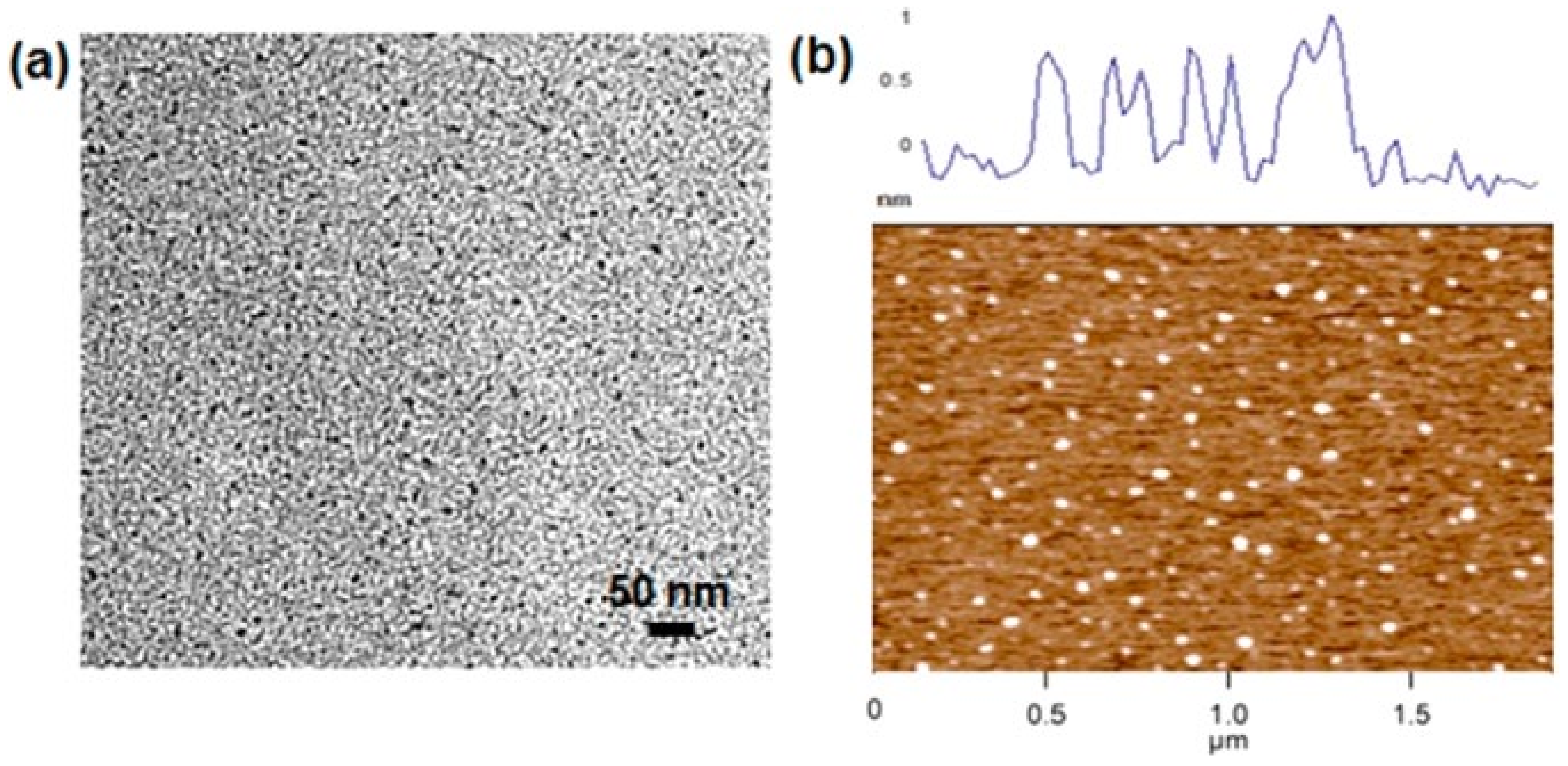
Figure 1. The sample of GQDs: (a) The TEM image and (b) AFM image with the corresponding height profile [15]. GQDs: graphene quantum dots; TEM: transmission electron microscope; AFM: atomic force microscope.
Physics 02 00027 g001
Figure 2. The high and low magnifications of SEM images of (a,c) PPy and (b,d) 10% GQD-doped PPy [15]. SEM: scanning electron microscope; PPy: polypyrrole; GQD: graphene quantum dot.
Physics 02 00027 g002
Figure 3. (a) CV curves of plain PPy and GQD-doped PPy CE. The inset is the CV curve of the Pt CE toward the I/I3 redox reaction. (b) Nyquist plots of bare PPy and GQD-doped PPy CEs. The inset shows the Nyquist plot of Pt CE [15]. CV: cyclic voltammetry; PPy: polypyrrole; GQD: graphene quantum dot; CE: counter electrode.
Physics 02 00027 g003
Figure 4. The schematic diagram of the electrolyte regeneration reaction for SrRuO3 and SRO–GQD hybrid CEs [17]. SrRuO3: Strontium Ruthenate; SRO–GQD: Strontium Ruthenate-graphene quantum dot; CEs: counter electrodes; FTO: Fluorine-doped tin oxide.
Physics 02 00027 g004
Figure 5. (a) The cyclic voltammograms of different CEs ((line a) SRO–GQD, (line b) SrRuO3 and (line c) Pt) recorded at a scan rate of 50 mV s−1 in an acetonitrile solution of 10 mM LiI, 1 mM I2 and 0.1 M LiClO4. (b) J–V characteristics of the DSSCs using different CEs measured under AM 1.5 simulated solar illumination (100 mW cm−2) [17]. CEs: counter electrodes; SRO–GQD: Strontium Ruthenate-graphene quantum dot; SrRuO3: Strontium Ruthenate; J–V: photocurrent density–photovoltage; DSSCs: dye-sensitized solar cells; AM: air mass.
Physics 02 00027 g005
Figure 6. (a) Nyquist plots derived from the EIS of the symmetrical dummy cells with (line a) SRO–GQD and (line b) SrRuO3 CEs. The equivalent circuit diagram used for the fitting of the Nyquist plots is inserted as the inset. (b) Tafel polarization curves of the symmetrical dummy cells [17]. EIS: electrochemical impedance spectroscopy; SRO–GQD: Strontium Ruthenate-graphene quantum dot; SrRuO3: Strontium Ruthenate; CEs: counter electrodes.
Physics 02 00027 g006
Figure 7. (a) TEM image of GQDs and its corresponding HRTEM image (inset). (b) AFM image of the GDs and its corresponding height profile (inset) [20]. TEM: transmission electron microscope; GQDs: graphene quantum dots; HRTEM: high resolution transmission electron microscope; AFM: atomic force microscope; GDs: graphene dots.
Physics 02 00027 g007
Figure 8. Cross-sectional SEM images of (a) PEDOT:PSS and (b) GD–PEDOT:PSS films. Corresponding top-view SEM images of (c) PEDOT:PSS and (d) GD–PEDOT:PSS films [20]. SEM: scanning electron microscope; PEDOT:PSS: poly(3,4-ethylene dioxythiophene):poly(4-styrene sulfonate); GD–PEDOT:PSS: graphene dot–poly(3,4-ethylene dioxythiophene):poly(4-styrene sulfonate).
Physics 02 00027 g008
Figure 9. (a) The J−V curves of the DSSCs with PEDOT:PSS and GD–PEDOT:PSS CEs measured at 100 mW cm−2 (AM 1.5 G). (b) The CV curves of the CEs with PEDOT:PSS and GD–PEDOT:PSS films. (c) Nyquist plots of the symmetric sandwich-type cells with PEDOT:PSS and GD–PEDOT:PSS CEs obtained at a zero bias potential. The inset shows the equivalent circuit [20]. J–V: Photocurrent density–photovoltage; DSSCs: dye-sensitized solar cells; PEDOT:PSS: poly(3,4-ethylene dioxythiophene):poly(4-styrene sulfonate); GD–PEDOT:PSS: graphene dot–poly(3,4-ethylene dioxythiophene):poly(4-styrene sulfonate); CEs: counter electrodes; AM1.5 G: the air mass is 1.5 (where the sun is about 41° above the horizon); CV: cyclic voltammetry.
Physics 02 00027 g009
Figure 10. External morphology of (a) MoO3 nanowires, and (bf) MoO3 nanowire sulfidized at different temperatures [23].
Physics 02 00027 g010
Figure 11. XRD spectra of MoO3-MoS2 nanowires on amorphous quartz sulfidized at various temperatures [23]. XRD: X-ray diffraction.
Physics 02 00027 g011
Figure 12. Electrochemical activity of MoO3-MoS2 nanowires [23]. (a) Cyclic voltammograms of nanowires sulfidized at 200 °C and 300 °C. The inset shows a comparison between nanowires sulfidized at 150 and at 200 °C. (b) The activity of the nanowires sulfidized at 200 °C presented with its iR-corrected data. iR correction: to remove the background interference; RHE: reversible hydrogen electrode. (c) Tafel slope produced by taking a derivative of the Tafel plot in (d). (d) Comparison with digitized data of HER measurements at 25 °C for other materials. HER: hydrogen evolution reaction. FTO: Fluorine-doped tin oxide.
Physics 02 00027 g012
Figure 13. SEM images of (ac) V-doped Ni3S2 nanowire arrays and (d) pure Ni3S2 nanoparticles on nickel foams [24]. SEM: Scanning electron microscope.
Physics 02 00027 g013
Figure 14. HRTEM image of single V-doped Ni3S2 nanowire arrays, (a) and EDS element maps of the single V-doped Ni3S2 nanowire: (b) nickel, (c) sulfur, (d) vanadium, and (e) oxygen. The inset in panel a is the SAED pattern [24]. HRTEM: high resolution transmission electron microscope; EDS: energy-dispersive X-ray spectroscopy; SAED: selected area electron diffraction.
Physics 02 00027 g014
Figure 15. (a) Polarization curves of samples after an activation test, (b) polarization curves of V-doped Ni3S2 nanowires after thousands of linear sweep voltammetry cycles and Pt/C, (c) Tafel plots of stabilized samples, and (d) Nyquist plots of stabilized V-doped Ni3S2 nanowire arrays and pure Ni3S2 nanoparticles [24].
Physics 02 00027 g015
Figure 16. HRTEM images of (a) WO3 NWs, and (b) WS2, (c) WSe2 and (d) WS2(1-x)Se2x NTs [27]. HRTEM: High resolution transmission electron microscope; NWs: nanowires; NTs: nanotubes.
Physics 02 00027 g016
Figure 17. HER electrocatalytic properties of WO3 NWs, WS2, WSe2, and WS2(1-x)Se2x NTs. (a) Polarization curves (after iR correction). (b) Corresponding Tafel plots. (c) Linear fitting of the capacitive currents of the catalysts versus the scan rate. (d) Nyquist plots of different samples [27]. HER: hydrogen evolution reaction; NTs: nanotubes; iR correction: to remove the background interference.
Physics 02 00027 g017
Figure 18. Schematic depiction of the synthesis of CoSe2 nanoneedle arrays [33].
Physics 02 00027 g018
Figure 19. SEM images of (a) Co3O4 and (b) CoSe2 nanoneedle arrays [33]. SEM: Scanning electron microscope.
Physics 02 00027 g019
Figure 20. (a) The polarization curves of different CEs. (b) The polarization curves of Co-BSND, CoSe2-PA, and CoSe2-BSND [33]. CEs: counter electrodes; Co-BSND: beaded stream-like Co nanoneedle array; CoSe2-PA: CoSe2 particle; CoSe2-BSND: beaded stream-like CoSe2 nanoneedle array.
Physics 02 00027 g020
Figure 21. (a) Tafel plots of the electrodes (b) The Bode plots of the CoSe2-BSND electrode at overpotentials of 0 and 150 mV. (c) The Nyquist plots of beaded stream-like CoSe2-BSND at overpotentials changing from 0 to 250 mV in a 0.5 M H2SO4 solution. (d) Comparison of the Nyquist plots [33]. CoSe2-BSND: beaded stream-like CoSe2 nanoneedle array.
Physics 02 00027 g021
Figure 22. Surface contact angles of water droplets on electrodes with (a) the CoSe2-BSND and (b) the CoSe2-PA electrodes [33]. CoSe2-BSND: beaded stream-like CoSe2 nanoneedle array; CoSe2-PA: CoSe2 particle.
Physics 02 00027 g022
Figure 23. SEM images of (a) MoS2, (b) graphene, and (c) MoS2/graphene powders [37]. SEM: Scanning electron microscope.
Physics 02 00027 g023
Figure 24. (a) J–V curves of DSSCs with Pt CE and MoS2/graphene CE at different thickness. (b) J–V curves of DSSCs with Pt and other CE. (c) Nyquist plots of the cells fabricated from MoS2/graphene CE prepared at various thicknesses. (d) EIS of the cells of MoS2/graphene CE with different graphene contents [37]. J–V: photocurrent density–photovoltage; DSSCs: dye-sensitized solar cell; CE: counter electrode; EIS: electrochemical impedance spectroscopy.
Physics 02 00027 g024
Figure 25. A schematic illustration of the electrocatalytic reduction of triiodide with the NM-8 composite films [38]. NM-8: nitrogen-doped graphene with MoS2.
Physics 02 00027 g025
Figure 26. (a) Illustration of how the electrolyte reacts with the material. (b) HRTEM images of as-synthesized NiS2@RGO (a,c) and NiS2 (b,d). (c) Raman spectra of NiS2 nanoparticles and NiS2@RGO, RGO, GO, and NiS2. (d) CV of iodide/triiodide redox species for NiS2 nanoparticles and NiS2@RGO, NiS2, Pt, and RGO counter electrodes [43]. HRTEM: high resolution transmission electron microscope; NiS2@RGO: NiS2 nanoparticles and reduced graphene oxide; RGO: reduced graphene oxide; GO: graphene oxide; CV: cyclic voltammetry.
Physics 02 00027 g026
Figure 27. Schematic illustration of the setup for the selenization of W on W-film coated (WSe2/W) counter electrode [46].
Physics 02 00027 g027
Figure 28. Surface morphology changes (a,b) before and (c,d) after selenization on the W surface [46].
Physics 02 00027 g028
Figure 29. (a) The illustration of the selenization of W on W-film coated (WSe2/W) structure as a CE in DSSCs. (b) Three-electrode cyclic voltammetry (CV) using WSe2/W and Pt as a WE in the electrolyte. (c) Tafel plot of symmetrical cells made of WSe2/W and Pt; (d) EIS of the spectra of WSe2/W and Pt [46]. CE: counter electrode; DSSCs: dye-sensitized solar cell; WE: working electrode; EIS: electrochemical impedance spectroscopy.
Physics 02 00027 g029
Figure 30. (a) A schematic diagram of the CVD design for the growth of N-GHBs. (b) Three types of N-GHBs, including pyridinic N, pyrrolic N, and quaternary N. (c) The distribution of various N-doped states in different N-GHBs samples [5]. CVD: chemical vapor deposition; N-GHBs: nitrogen-doped graphene hollow nanoballs.
Physics 02 00027 g030
Figure 31. (a) The SEM images and (b) HRTEM image of N-GHBs; (c) Photocurrent density-voltage curves; and (d) EIS measurements of various electrodes [5]. SEM: scanning electron microscope; HRTEM: high resolution transmission electron microscope; N-GHBs: nitrogen-doped graphene hollow nanoballs; EIS: electrochemical impedance spectroscopy.
Physics 02 00027 g031
Table 1. Performance parameters of DSSCs with different amounts of GQD-doped PPy CEs under AM1.5 G illumination [15]. DSSCs: dye-sensitized solar cells; GQD: graphene quantum dot; PPy: polypyrrole; CE: counter electrode; AM1.5 G: the air mass is 1.5 (where the sun is about 41° above the horizon); V/V: volume percentage concentration; PCE: power conversion efficiency; Voc: open-circuit voltage; Isc: short cut current; FF: fill factor.
GQD Ratio (V/V) (%)PCE (%)Voc (V)Isc (mA cm−2)FF (%)
04.460.7212.8348.60
34.890.7413.8147.90
105.270.7214.3650.80
155.000.7313.8049.80
204.940.7312.2355.60
254.670.7012.0755.60
304.620.7111.4157.30
Pt6.020.7012.8167.50
Table 2. Electrochemical parameters for different counter electrodes [20].
CE withCathodic Current Density a (mA cm−2)ΔEp a (mV)Rctb (ohm)
PEDOT:PSS−0.3943610.38
GD-PEDOT:PSS−1.583477.92
a The values are obtained from CV; b The values are obtained from EIS; CEs: counter electrodes; PEDOT:PSS: poly(3,4-ethylene dioxythiophene):poly(4-styrene sulfonate); GD–PEDOT:PSS: graphene dot–poly(3,4-ethylene dioxythiophene):poly(4-styrene sulfonate); ΔEp: peak separation. Rct: charge-transfer resistance.
Table 3. Photovoltaic parameters of the DSSCs with PEDOT:PSS and with GD-PEDOT:PSS counter electrodes [20].
DSSC withη (%)Voc (mV)Jsc (mA cm−2)FF
PEDOT:PSS CE5.1466812.820.60
GD-PEDOT:PSS CE7.3671814.700.70
DSSCs: dye-sensitized solar cells; PEDOT:PSS: poly(3,4-ethylene dioxythiophene):poly(4-styrene sulfonate); GD–PEDOT:PSS: graphene dot–poly(3,4-ethylene dioxythiophene):poly(4-styrene sulfonate); CE: counter electrode; η: the cell efficiency of the DSSC; Voc: open-circuit voltage; Jsc: photocurrent density; FF: fill factor.
Table 4. HER performance of one-dimensional TMDCs.
CatalystMorphologyOverpotential
(mV)
Corresponding Tafel Slope
(mV dec−1)
Current Density (mA cm−2)ElectrolyteRef.
Core-shell
MoO3-MoS2
nanowire150–20050–60N/A0.5 M H2SO4[23]
V-doped Ni3S2nanowire157112N/A1 M KOH[24]
WS2(1-x)Se2x /CFsnanotube150–2001050.0291 M H2SO4[27]
WSe2/CFsnanotube250–300990.0031 M H2SO4[27]
WS2/CFsnanotube250–3001130.00121 M H2SO4[27]
CoSe2-BSNDnanoneedle125480.0430.5 M H2SO4[33]
HER: hydrogen evolution reaction; TMDCs: transition metal dichalcogenides; CF: carbon fiber; CoSe2-BSND: beaded stream-like CoSe2 nanoneedle array.
Table 5. Analysis of DSSCs based on the films of Pt, NGr, MoS2, and NM-8 CE [38].
CEJpc (mA cm−2)ΔEp (V)Jsc-IPCE (mA cm−2)k0 (cm s−1)Ae (cm2)Rs (Ω cm2)Rct (Ω cm2)ZW (Ω cm2)Rct-Tafel (Ω cm2)J0 (mA cm−2)
Pt2.550.3812.823.75 × 10–30.19615.2310.158.499.881.30
NGr0.490.7210.161.34 × 10–30.39016.3130.1735.4633.930.38
MoS20.520.9110.897.04 × 10–40.13621.1424.9327.2024.610.52
NM-82.060.5812.032.40 × 10–30.73015.6016.7318.1216.150.80
DSSCs: dye-sensitized solar cells; NGr: nitrogen-doped graphene; NM-8: nitrogen-doped graphene with MoS2; CE: counter electrode; Jpc: peak current density; ΔEp: peak separation; Voc: open-circuit voltage; Jsc: photocurrent density; IPCE: incident photo-to-current conversion efficiency; k0: rate constant; Ae: surface area; Rs: solution resistance; Rct: charge-transfer resistance; Zw: warburg imperdance; J0: exchange current density.
Table 6. A schematic illustration of the photovoltaic and electrochemical parameters for different CEs [43].
CEsVoc (mV)Jsc (mA cm−2)FFPCE (%)Rs (Ω cm2)Rct (Ω cm2)Epp (V)
NiS273814.420.667.025.108.800.65
NiS2@RGO74916.550.698.556.402.900.50
RGO71610.980.403.1414.20100.20N/A
Pt73915.750.708.152.200.500.44
CEs: counter electrodes; Voc: open-circuit voltage; Jsc: photocurrent densit; FF: fill factor; PCE: power conversion efficiency; Rs: solution resistance; Rct: charge-transfer resistance; Epp: peak-to-peak separation.