Article

Prosthetic Sockets: Tensile Behavior of Vacuum Infiltrated Fused Deposition Modeling Sandwich Structure Composites

1
Department of Mechanical and Aerospace Engineering, University of California San Diego, San Diego, CA 92093, USA
2
Department of Bioengineering, University of California San Diego, San Diego, CA 92093, USA
3
The Robotics Institute, Carnegie Mellon University, Pittsburgh, PA 15213, USA
4
Department of Nanoengineering, University of California San Diego, San Diego, CA 92093, USA
5
California Institute for Telecommunications and Information Technology (Calit2), San Diego, CA 92093, USA
*
Author to whom correspondence should be addressed.
Prosthesis 2022, 4(3), 317-337; https://doi.org/10.3390/prosthesis4030027
Submission received: 12 April 2022 / Revised: 14 June 2022 / Accepted: 20 June 2022 / Published: 22 June 2022
(This article belongs to the Special Issue 3D Printing Strategies for Limb Prostheses)

Abstract

:
The development of novel materials will enable a new generation of prosthetic devices to be built with additive manufacturing (AM). Vacuum infiltrated sandwich structure composites are a promising approach for building prosthetic sockets via AM. In this paper, we test the tensile properties of 18 different composite material configurations using ASTM D638. These composites were manufactured using a custom vacuum infiltration method and had varying filament materials, infiltrated matrix materials, and print directions. Several material-matrix-print composites showed higher ultimate tensile strengths and reduced anisotropy compared to full-infill control samples. However, the mechanical properties of these composites were limited by a large degree of porosity due to the manufacturing method. Still, the results were sufficiently promising to create a proof of concept prosthetic socket via the vacuum infiltration method. Future research should focus on reducing porosity defects and investigating additional material-matrix-print combinations.

1. Introduction

The majority of clinicians still utilize traditional layup methods and plaster of Paris fitting models to shape custom prostheses for persons with limb loss. These traditional layup methods have several disadvantages which can be overcome by building prosthetic sockets with digital techniques [1]. Hands-on methods are destructive, requiring clinicians to destroy intermediate plaster limb models (which take incredible expertise and skill to shape.) With digital models of patient limbs, clinicians can keep track of the exact shape and morphology of an amputee at a specific point in time and see how their residual limb fluctuates in size [2]. Digital limb models still require clinician experience to shape into prosthetic sockets via CAD software, but computerized workflows offer the ability to quickly make non-destructive changes [3]. Importantly, with digital limb models, clinicians can easily remanufacture prosthetic sockets for patients whose limbs fail prematurely without requiring additional measurements.
Additive manufacturing (AM) is a key technology for bridging the digital divide and bringing computer designed prosthetic socket models into reality. Researchers have been using 3D printing and other CAD/CAM methods to build prosthetic sockets for more than 30 years [4]. AM is the leading method for fabricating prosthetic sockets designed via computer aided design (CAD) [3] because AM methods can easily accommodate the complex and unique shapes of residual limbs. AM methods also have a distinct advantage in their ability to utilize new topologies and create prosthetic sockets that are fully integrated monocoque structures [5]. Despite the method’s popularity, strength limitations of the materials themselves used in printing have been a major obstacle to widespread clinical implementation [6].
Previous researchers attempted to strengthen AM manufactured prosthetic sockets by coating them with polymeric materials [7]. This had a promising, but ultimately limited impact on the material’s strength. Recent developments in additive manufacturing, such as fill compositing [8] and direct printing of sandwich structure composites [9], have the potential to result in stronger reinforcement of AM printed parts. Building off these advancements, we propose that using vacuum infiltrated fill compositing in addition to printed sandwich structure configurations can improve the mechanical properties of AM printed prosthetic sockets. If successful, improving the mechanical performance of these AM materials could accelerate the shift of modern prosthetic clinics towards digital approaches and the advantages they entail.

2. Background

2.1. Material Challenges

Prosthetic sockets, due to their custom nature, are difficult to test and validate for safety. There are no international standards for strength verification of prosthetic sockets, but it is common for researchers to base their strength calculations on the P5 activity level listed in ISO 10328 [10]. Evaluations of the strength of prosthetic socket materials have led to mixed results. Historically, additively manufactured sockets have not been able to reach acceptable levels of safety [3,6].
In the authors’ previous work [11] as well as dynamic testing experiments by Saey et al. [12], it was revealed how crucial the junction between the AM socket and modular component interface is. Without careful design consideration, these interfaces can fail at much lower strengths or cycles than predicted. Recent work by van der Stelt et al. [13] showed that AM sockets fail in brittle fracture at this interface before reaching terminal fatigue strength.
Developments in AM materials have improved the feasibility of using the fused deposition modeling (FDM) printing technology for manufacturing prosthetic sockets. Several studies identified AM polymeric materials which could meet the ISO load requirements [14,15,16]. However, these investigations were limited to static testing scenarios and these sockets also failed catastrophically in almost every case. Circumferential brittle cracks were the most common forms of failure. These researchers emphasized the importance of new material research to identify novel materials which may meet conditions not investigated previously.

2.2. New Material Approaches

Developing new additive manufacturing filament materials is an approach that is promising and is an active area of research [17]. Recent research has focused on improving the strength of existing filaments utilizing chopped fiber or particulate additives [18,19] Significant advances in continuous fiber filament reinforced PLA composites were reported by Maqsood et al. [20]. Despite the promise of stronger filament materials for prosthetic sockets, development will take time. Furthermore, while these filament fiber composites often result in stiffer materials, they do not necessarily increase the tensile strength or improve the strength to weight ratio. Improving the properties of existing filament materials in a structure as large as a prosthetic socket requires a different approach.
Belter et al. [8] reported that they were able to significantly improve the performance of additively manufactured robotics components using a fill compositing technique. In this technique, they printed hollow components which they filled with epoxy utilizing a syringe extruder. With this technique they were able to significantly improve the flexural strength of additively manufactured ABS plastic specimens. The key limitation of this technique was the manual injection of polymer, limiting the scalability of this technique.

2.3. Sandwich Structure Composites

Multi-material polymer-based sandwich structure composites have been of significant interest to both the industrial and research community in recent years [21]. A sandwich structure composite is a laminate that consists of two thin facesheets surrounding a thicker core material [22]. The components of these polymeric composites are immiscible with the binder, which results in a cohesive interface [23]. Imperfections, such as the presence of voids and delaminations often serve as crack initiation sites resulting in material failure [24].
Galatas et al. [25] studied whether it would be possible to enhance the mechanical properties of additively manfactured ABS by adding carbon fiber reinforced polymer (CRFP) layers to create a sandwich structure. They varied the internal density of the printed ABS core using several infill patterns and built a test matrix to isolate the strength contribution of the CRFP facesheets. They found that they were able to increase the ultimate tensile strength by a factor of 9 after normalizing for density, but the addition of CRFP facesheets caused brittle failure.
Other researchers have looked into directly printing sandwich structure composites in order to improve the mechanical properties of additively manufactured components. Baca Lopez et al. [9] tested the mechanical behavior of ABS, PLA, and HIPS filament materials in several sandwich structure configurations. Their experiments revealed that PLA outer skins with ABS cores were the best sandwich structure configuration for tension resulting in the highest tensile strength, stiffness, and strain at break. Crucially, this work showed that sandwich structural configurations could result in stronger AM parts than parts built out of a single homogeneous material.

3. Materials and Methods

3.1. Materials

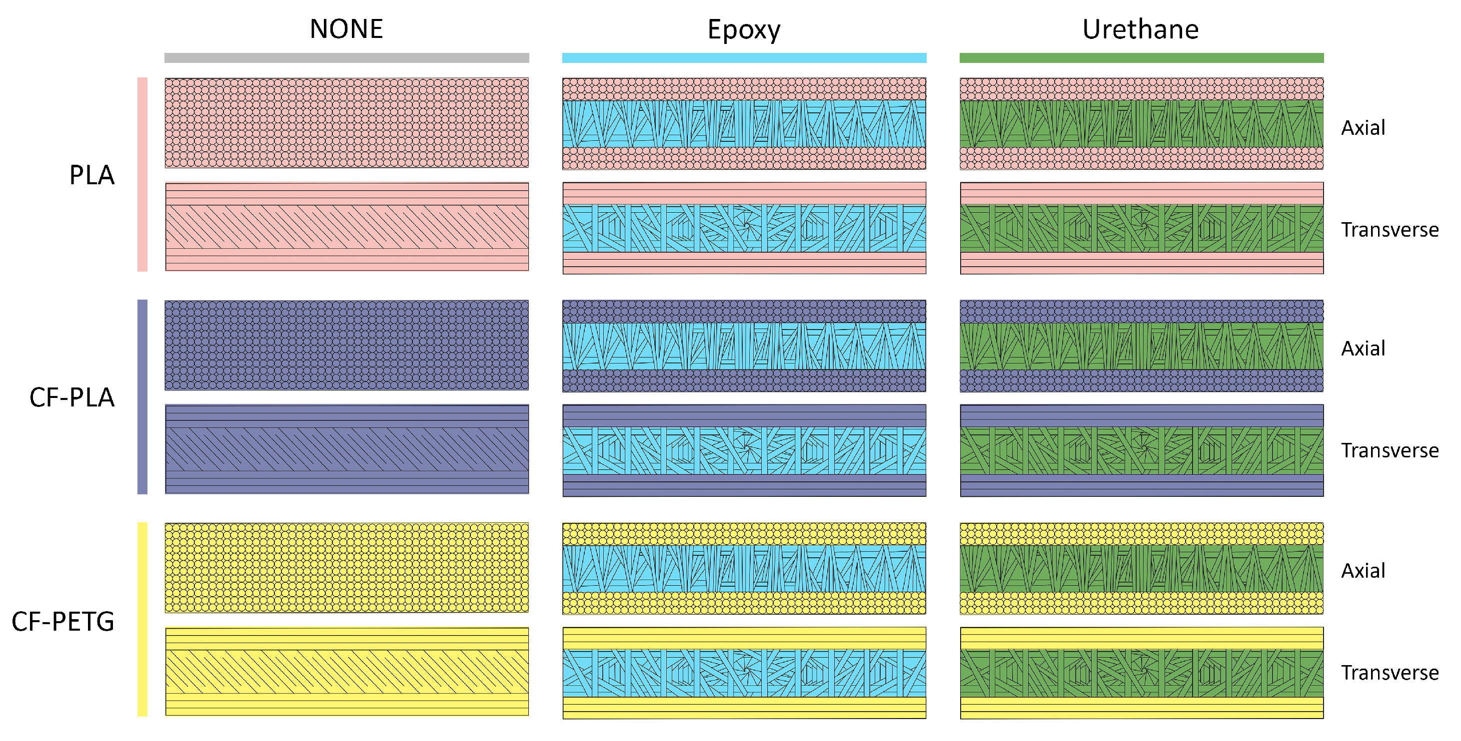
We hypothesize that there is a filament-matrix composite material that will increase the tensile strength of additively manufactured prosthetic sockets. Using additive manufacturing to build face sheets, and vacuum infiltration to create a polymer core is an innovative way to generate sandwich structure composite materials for building prosthetic sockets. In this research, we create sandwich structure composites out of 3 filament materials (PLA, CF-PLA, CF-PETG), 2 resin infiltrating materials (Epoxy, Urethane), and in 2 print directions (0° Axial, 90° Transverse), Figure 1. The properties of the filament materials and resin infiltrating materials are listed in Table 1.
Using a Raise3D Pro2Plus 3D Printer, large sheets measuring 35 cm by 27 cm and 5 mm thick were printed for each filament material (Figure 2). Printing parameters for bed temperature, nozzle temperature, nozzle size (0.4 mm) and print speed were chosen based on the manufacturers recommended specifications [26,27,28]. For experimental controls, test sheets of each filament material at 100% infill were printed using the 0°–45° raster pattern in Figure 3. For the vacuum infiltration experiments, it was not possible to print completely hollow sheets without significant warping to the outer faces due to thermal stresses imparting during the printing process. Geometric integrity was maintained by using a 20% sparse infill pattern printed at raster angles of 0°–30°–60°–90° visible in Figure 3.
After the large sheets were manufactured using 3D Printing, they were infiltrated with resin using the setup outlined in Figure 4. The sheets were wrapped in vacuum bagging, and sealed. Additional sealant tape ensured that resin flowed through the sheets. The source end of the setup was outfitted with a resin jacket to ensure even distribution of resin along the entire edge of the sheet. The sink end of the setup utilized bleeder and breather cloths to allow excess resin to pass while simultaneously reducing the presence of air bubbles. A vacuum pump drew resin through the system and excess resin was caught in a resin trap. Both ends of the infiltration setup contained a valve which was sealed to maintain a state of vacuum while the resin cured.
Critically, when testing the printed samples, it was important reduce the contribution of print edge defects which can cause crack initiation due to air voids or weak inter-layer bonding [31,32]. To reduce the chance of improper crack initiation at the interlayer bonding site, tensile sample coupons were cut out of the large sheets using a waterjet. These tensile samples were prepared in accordance with ASTM D638 and were cut in 2 perpendicular orientations out of the same sheet to evaluate orthotropic behavior of the materials (Figure 5).

3.2. Methods

These samples were tested using the ASTM D638 test methods [33] to determine mechanical properties. For each of the 18 configurations, ASTM D638 requirements for number of tensile samples to ensure statistical significance (n > 5) were met and exceeded. In total, 126 tensile specimens were tested. Machine compliance was recorded and this correction was applied to the raw data using the method described in [34]. This compliance correction ensured that the analyzed displacement data represented deformation of samples instead of both the samples and the load frame. Machine compliance was measured by inserting a steel dummy specimen into the tensile grips at a grip distance of 0 mm and measuring deflection of the load frame. The machine load-displacement curve was then subtracted from the sample load-displacement curve, resulting in a compliance corrected load-displacement curve. Since the tensile testing machine (Instron 3367) was much stiffer than the tested polymeric samples, machine compliance was not found to meaningfully alter the analyzed mechanical properties of the materials.

4. Results

4.1. Tensile Data

For axial samples (Table 2), CF PLA + Epoxy was the stiffest material with a Young’s Modulus of 4390 ± 120 MPa, while PLA had the lowest stiffness with a value of 2310 ± 360 MPa (Figure 6). For each of the 3 filament materials, infiltration with either epoxy or urethane slightly increased stiffness, with the exception of CF PLA + Urethane where the stiffness was significantly reduced (Figure 6). CF PETG + Urethane had the highest ultimate tensile strength with a value of 42.9 ± 3.4 MPa, while PLA + Epoxy had the lowest strength with a value of 20.9 ± 0.5 MPa (Figure 7). For each of the 3 filament materials, infiltration with epoxy significantly reduced the axial ultimate tensile strength whereas infiltration with urethane slightly increased the ultimate tensile strength (Figure 7).
For transverse samples (Table 3), CF PLA + Epoxy once again was the stiffest material with a Young’s Modulus of 2880 ± 260 MPa, while CF PETG had the lowest stiffness with a value of 950 ± 50 MPa (Figure 6). In all cases, for each of the 3 filament materials infiltration with either epoxy or urethane significantly increased the stiffness of the composite. CF PLA + Urethane had the highest ultimate tensile strength with a value of 20.8 ± 3.5 MPa while CF PETG had the lowest strength with a value of 5.7 ± 0.5 MPa (Figure 7). Infiltration with epoxy was found to slightly increase the ultimate tensile strength of composites made with CF PETG and CF PLA, while infiltration with urethane was found to significantly increase the ultimate tensile strength of composites made with these filament materials. However, inclusion of either epoxy or urethane decreased the ultimate tensile strength of composites made with PLA (Figure 7).
Looking at the Ashby plots (Figure 8), the relationship between the stiffness and strength of the composite materials becomes clear. For axial samples, CF PETG + Urethane, CE PETG, and CF PLA were comparably stiff with high ultimate tensile strengths. PLA + Epoxy had the lowest ultimate tensile strength of the axial samples with a relatively lower stiffness as well. For transverse samples, CF PETG + Urethane and CF PLA + Urethane both have high ultimate tensile strengths but CF PLA + Urethane is a stiffer material. CF PETG clearly had the lowest ultimate tensile strength and stiffness of the transverse samples.
In Table 4, the degrees of anisotropy for stiffness and ultimate tensile strength are calculated using the mean values from Table 1 and Table 2. These ratios reveal the difference in stiffness and strength between the axial and transverse samples. Values close to 1 represent highly isotropic materials, wheras values close to 0 represent highly anisotropic materials. CF PETG had the highest degree of stiffness anisotropy with the axial stiffness being on average 3.84 times stiffer than the transverse stiffness. CF PLA + Urethane had the lowest degree of stiffness anisotropy with the axial stiffness being on average 1.06 times stiffer than the transverse stiffness. Incorporating either urethane or epoxy into the three filament materials resulted in a reduction in the degree of stiffness anisotropy. Similar to the results for stiffness, CF PETG had the highest degree of ultimate tensile strength anisotropy with the material being on average 7.31 times stronger in the axial direction than the transverse direction. CF PLA + Urethane also had the lowest degree of ultimate tensile strength anisotropy with the material only being on average 2.02 times stronger in the axial direction than the transverse direction. Incorporating either urethane or epoxy into the three filament materials resulted in a reduction in the degree of strength anisotropy for all materials with the exception of PLA + Urethane. In the case of PLA + Urethane, the degree of anisotropy increased by a small amount due to an increase in axial ultimate tensile strength.
Normalizing the ultimate tensile strength of each material by their measured density, we can calculate specific strength for each material (Table 4). These specific strengths largely mirror the ultimate tensile strength results previously discussed with small differences. CF PETG + Urethane had the highest specific strength in both the axial and transverse directions, 37,500 Pa·m3/kg and 18,300 Pa·m3/kg, respectively. PLA + Urethane had the lowest specific strength in the axial direction (19,000 Pa·m3/kg), whereas CF PETG had the lowest specific strength in the transverse direction (5100 Pa·m3/kg). Under axial loading, infiltrating any of the three filament materials with urethane increased the specific strength slightly, while infiltrating these materials with epoxy significantly reduced the specific strength. Under transverse loading, infiltration with urethane resulted in small to large improvements in the specific strength while infiltration with epoxy resulted in medium improvements in specific strength, with the exception of PLA + Epoxy where there was a drop in specific strength.

4.2. Fracture Surfaces

In Figure 9, the characteristic stress–strain curves reveal both ductile and brittle behavior of the composite materials tested in these experiments under axial loading. PLA exhibited significant plastic deformation before failure, resulting in an average elongation of 4.34 ± 0.97% (Table 2). PLA’s stress–strain curve also indicated strain hardening behavior [35]. CF PLA also exhibited a large degree plastic deformation, to a lesser degree, and resulted in an average elongation of 2.02 ± 0.21% before failure. Most of the other materials loaded axially showed lesser degrees of ductile behavior with the exception of PLA + Epoxy which exhibited brittle behavior.
Comparing these observations to the axial fracture surfaces in Figure 10, it can be inferred that PLA and CF PLA indeed show visible signs of plastic deformation. As the polymeric materials deform plastically, we can observe a color change with the filament fibers turning white from their original black color. This phenomenon is commonly referred to as stress whitening [36]. This color change is not present in the case of PLA + Epoxy. The smooth fracture surface of PLA + Epoxy confirms the suspected brittle failure in the elastic regime. CF PETG does not show a large degree of stress whitening, but instead the rough surfaces with fibers in and out of the plane of focus suggesting tortuous crack growth and ductile fracture. In all axial infiltrated samples, there is clear evidence of porosity at the fracture surface. This porosity likely contributed to the failure of these samples. This is certainly the case for PLA + Epoxy, PLA + Urethane, CF PLA + Urethane, and CF PETG + Urethane as hackles visibly radiate from the voids in these samples.
Referring back to Figure 9, the characteristic stress–strain curves for composite materials tested under transverse loading revealed primarily brittle behavior. CF PLA + Urethane and CF PETG + Urethane both exhibit plasticity with ultimate tensile strains of 1.02 ± 0.14% and 1.59 ± 0.41% respectively (Table 3). These ultimate tensile strains are lower than the same composites loaded axially, but larger than the values for their respective non-infiltrated filaments. PLA + Epoxy, PLA + Urethane, CF PLA + Epoxy, CF PETG + Epoxy, and CF PETG show brittle failures in the linear elastic regime. PLA + Epoxy is the most brittle of these samples with an average ultimate tensile strain of only 0.37 ± 0.03%.
Examining the transverse fracture surfaces in Figure 11, there is evidence for brittle fracture in these composite materials. All of the samples loaded transversely break cleanly along the filament lines from the additive manufacturing process. There are slight indications of strain whitening in CF PETG + Urethane, CF PLA + Urethane, and PLA, but less so than those of the axial samples. PLA + Epoxy and PLA + Urethane show the cleanest breaks along the filaments and within their infiltrated cores, while CF PLA + Urethane and CF PETG + Urethane exhibited the most plasticity of the transverse samples in their stress–strain curves, the fracture surfaces indicate rapid crack growth suggesting brittle fracture. Once again, porosity was evident in the infiltrated samples and many cracks initiated at these voids. For CF PETG + Urethane, the presence of hackles radiating in multiple directions on the infiltrated surface suggests that multiple cracks initiated on the voids, then coalesced to form a crack plane causing failure.
Comparing the experimentally obtained material properties with the reference values for density, modulus, and ultimate tensile strength on the control samples (Table 5) it can be observed that all three results are less than expected for bulk materials. The fracture surfaces can help give insight as to why the experimentally obtained values are lower than the reference values for the bulk materials. It is relatively well known that additively materials have properties inferior to their bulk counterparts [37,38]. This is especially true with fused deposition modeling because voids form between the filament fibers during the printing process. These gaps can cause stress concentrations on individual fibers leading to premature failure. In Figure 11, it is clear that there are noticeable gaps between the filament fibers for the PLA, CF PLA and CF PETG control samples. These gaps can help explain why the samples have a reduced density and stiffness compared to their bulk counterparts. The filament fibers also display a poor degree of fusion between the layers. This poor fusion contributes to the inferior ultimate tensile strength by causing these filament fibers to neck and locally deform plastically. Recent research has focused on improving the fusion between these filament fibers using the ANOVA technique to optimize process parameters [39].

4.3. Porosity Estimates

Since all of the vacuum infiltrated samples demonstrated significant porosity on their fracture surfaces, it is necessary to quantify the degree of porosity. Cross sectional imaging is a common and recommended method to achieve this [22]. To quantify the degree of porosity, the distal surface (non-fractured end) of every vacuum infiltrated tensile sample (80 total) was imaged via high resolution photographs (Figure 12A). These surfaces were imaged because they could provide a more random sampling of porosity compared to the fracture surfaces. The fracture surfaces showed a bias towards failure on porosity whereas the distal ends provide a non-biased snapshot of the cross sectional porosity. Following this, the background in each image was removed using Adobe Photoshop resulting in an isolated sample (Figure 12B). At this stage, the full color RGB photographs were converted into 32 bit greyscale images in ImageJ to facilitate threshold analysis. The region of interest was identified and the total area measured by setting the maximum threshold to 250 then creating a boundary around the sample area (Figure 12C). The threshold was then reduced to 50 to isolate pores on each sample. This threshold successfully identified areas containing porosity using the ImageJ built-in “Analyze Particles…” function (Figure 12D). To reduce false positive results, areas smaller than 0.1 mm2 were excluded from porosity calculations. The average pore diameter and area fraction of porosity were measured for each sample and the results are reported in Table 6.
In Table 6, area fraction estimates from the ImageJ analysis correlate the observation that the vacuum infiltrated samples contain a large degree of porosity. The highest area fraction observed was for CF PETG + Epoxy (4.76 ± 6.96%) while the lowest area fraction observed was for CF PLA + Urethane (0.59 ± 0.84%). This porosity certainly limits the strength of the composite materials. It is important to keep in mind that these area fractions overestimate the volume fraction of porosity. For spherical and ellipsoid voids, the area fraction will always be larger than the volumetric fraction due to the geometric relationship between projected area of an ellipsoid and its volume. The ratio between the area fraction and volume fraction also grows larger as pore size decreases, meaning that small pores affect the measured area far more than they affect the actual volume. Assuming spherical particles, and that the observed areas corresponds to a unit cell with an equivalent number of pores, it is possible to estimate the volume fraction of pores. The final column in Table 6 corresponds to a conservative estimate of volume fraction. The ratio between the calculated area fraction and estimated volume fraction is 3:2, consistent with [40].

5. Discussion

5.1. Comparison with Theoretical Models—Rule of Mixtures

For simple first order approximations of the mechanical properties of composite materials, the Voigt and Reuss models (referred to as the Rule of Mixtures) are often used to predict material properties [41]. For unidirectional composites reinforced axially, the contribution of each material to the final property is proportional to the volume fraction of each component (Equation (1)).
P c = i = 1 n P i V i
In this Equation, P is a property and V denotes volume fraction. The subscript c indicates the composite, and the subscript i indicates the ith component of a total of n components. For a simple two phase composite n = 2 where the property P is the Young’s Modulus E, the equation simplifies to Equation (2):
E c = E f V f + E m V m
For unidirectional composites loaded transversely, the model of the system changes because the components are under equal stress leading to Equation (3).
1 P c = i = 1 n V i P i
Again, for a simple two phase composite n = 2 where the property P is the Young’s modulus E, the equation simplifies to Equation (4):
1 E c = V f E f + V m E m
Because equal stress conditions are less realistic than equal strain, the Reuss model for transverse loading will always be less accurate than the Voigt Model for axial loading [41].
Unfortunately, both of these models are not sufficient to account for the complexity of the mechanical behavior in most composite materials. This is especially true when interfacial failure, void presence, fiber misalignment, statistical dispersion among other defects are considered [22,42,43]. Critically, the porosity in the matrix must be accounted for. The relative density of porosity is the single most important factor affecting the mechanical properties of porous materials [44].
For this research, simple modifications to the Rule of Mixtures are proposed. The materials studied are simple two phase composites, but have additional complexity due to additive manufacturing and vacuum infiltration induced defects. Modified Rule of Mixtures (MRoM) equations for axial loading are presented below (Equations (5) and (6)).
E c = η 0 E f V f + E m V m ( 1 φ ) 2
σ c = η 0 σ f V f + σ m V m ( 1 φ ) 2
E and σ refer to the Young’s modulus and ultimate tensile strength, respectively. The subscripts c, f, and m refer to the composite, filament material, and infiltrated matrix. For materials with porosity relative densities > 0.3, voids behave as isolated pores in a solid. Previous theoretical and experimental studies have shown that a term ( 1 φ ) 2 can be applied to the matrix as a "porosity correction factor" [40,43]. Here φ is the volume fraction of porosity.
η 0 describes the Krenchel fiber orientation efficiency factor of the filaments in the matrix [45] (Equation (7)). In this equation, θ n is the angle between groups of parallel filament fibers and the load direction. a n is the fraction of filament fibers oriented at θ n .
η 0 = i = 1 n a n c o s 4 θ n
Simple application of this orientation efficiency factor would result in zero contribution from filament fibers perpendicular to the load direction. This is not true, and corrections such as the ten percent rule [46] bound the failure envelope for fiber reinforced composites. In additively manufactured materials, the volume fraction of filament fibers are very high (often continuous) meaning there will be a significant transverse response. To account for this, it is more appropriate to bound this envelope by the ratio of anisotropy for each relevant property α = P t P a , where P t and P a are the transverse and axial properties of interest. This leads to a modified Krenchel efficiency factor (Equation (8)):
η 0 = i = 1 n a n ( ( 1 α ) c o s 4 θ n + α )
The equations for transverse loading are similar to those of the Reuss model. In this case, all correction factors η 0 and ( 1 φ ) 2 , move to the denominator of Equation (Equations (9) and (10)).
1 E c = V f η 0 E f + V m E m ( 1 φ ) 2
1 σ c = V f η 0 σ f + V m σ m ( 1 φ ) 2
Table 7 and Table 8 plus Figure 13 summarize the expected values for stiffness and ultimate tensile strength calculated using the Rule of Mixtures (RoM) and Modified Rule of Mixtures (MRoM). The input material properties for RoM and MRoM are found in Table 1 with a volume fraction of 0.584 for the filament fibers and 0.416 for the volume fraction of resin. The MRoM model utilizes an assumed porosity φ of 0.03, while values for η 0 were calculated using filament anisotropy values reported in Table 4 and raster pattern geometry.
Examination of the values for axial stiffness and strength, Table 7 plus Figure 13, show that both the RoM and MRoM over predict the axial ultimate tensile strength of the composite materials. This is consistent with previous applications of RoM and MRoM models [42,43,47]. The MRoM better predicts the axial UTS in every case, but still over predicts strength by a large margin. Prediction of axial stiffness is much better than the strength predictions with relative error being as low as 0.8% for PLA + Epoxy. The MRoM had a slight edge in this case with a lower average error. Notably, CF PLA + Epoxy outperformed the predicted stiffness for both RoM and MRoM models with relative errors of −7.3% and −13.4% respectively.
Inspecting the transverse values of stiffness and strength, Table 8 plus Figure 13, it is clear that the RoM over predicts both material properties by a large margin. The values predicted by the RoM model are significantly different from the experimentally reported values. The MRoM model more accurately predicts the transverse stiffness and strength in every single case. The MRoM consistently underpredicts the transverse stiffness by a small margin and overpredicts the transverse tensile strength by a larger margin. Interestingly, CF PLA + Urethane as well as CF PETG + Urethane outperform their strength predictions from the MRoM model with relative errors of −3.5% and −71.6% respectively.
While the results of the RoM and MRoM models are interesting and useful for predicting properties of novel composite materials, they are limited in their effectiveness. As a first order approximation, the RoM model typically describes the theoretical upper and lower bounds of composite strength and stiffness [41]. The MRoM model improves on this by including some geometric factors and defects into account, but more elaborate models have been proposed. Prediction of material properties could be improved by utilizing models such as the Volume Average Stiffness (VAS) method [43,48,49].

5.2. Impact on Additive Manufacturing

The novel composite materials developed in this work have many implications for additive manufacturing. Often it is not possible to print components in a favorable raster orientation due to machine limitations. In every single case tested in these experiments, it was observed that the stiffness anisotropy due to additive manufacturing was reduced. This means that when operating under linear elastic conditions, engineers and designers have more geometric freedom for designing additively manufactured components. The reduction in stiffness anisotropy means that parts can be loaded in more configurations. Similarly, the strength anisotropy was reduced in every single case tested except one (PLA + Urethane). In this outlier, the specific strength of the material actually increased. This makes a strong case that vacuum infiltration improves the isotropy properties of these materials. For both stiffness and strength, this internal reinforcement impacted the transverse loading condition more dramatically than the axial loading condition. Since the transverse loading direction is the weakest, any improvements in transverse stiffness or strength improve the usefulness of a material matrix combination.
Importantly, there are limitations to this vacuum reinforcement method for additive manufacturing. First, not every geometry that can be additively manufactured can be vacuum infiltrated because of the need for surrounding the part with vacuum bagging. In addition, the observed porosity in these experiments was the cause of failure for most infiltrated specimens, while some degree of porosity is inevitable, the strength of these composites could be much better if processing conditions were improved to reduce the number and size of voids. Other limitations include leakage of resin through the walls of 3D printed parts. This issue was not significant enough to drastically change the intended geometry but would require post-processing such as sanding to clean off. Other remnants of the vacuum infiltration process such as the sealant tape and the vacuum bagging themselves also need to be cleaned before the parts could have an acceptable surface finish. Still, vacuum infiltration is much better suited to reinforcement of large scale components than fill compositing [8] thus many of these limitations are still outweighed by the method’s benefits.

5.3. Feasibility for Manufacturing Prosthetic Sockets

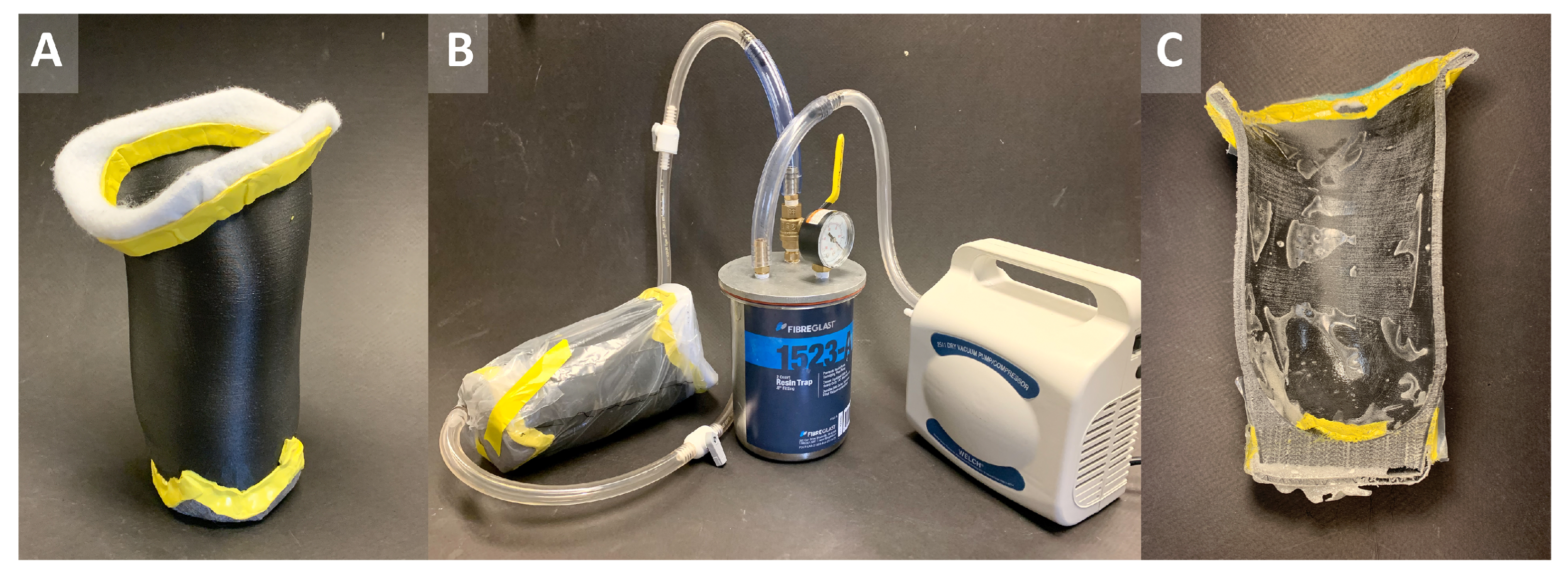
Since the data presented in the experiments was promising, especially for the CF PLA + Urethane and CF PETG + Urethane combinations, the next step was to evaluate the feasibility of using vacuum infiltration to reinforce an additively manufactured prosthetic socket. A transtibial prosthetic socket was 3D printed utilizing CF PETG as the filament material with a wall thickness of 5 mm and raster pattern identical to the printed test sheets (Figure 14A). The distal and proximal ends of the printed socket were sanded to reveal the underlying infill layer, then breather and bleeder cloths were affixed using sealant tape. The entire assembly was infiltrated with Urethane using the same method as the printed test sheets (Figure 14B). After curing, the sample was cut in half to inspect the cross section (Figure 14C).
Overall, this socket represents a successful proof of concept for strengthening additively manufactured prosthetic sockets with vacuum infiltration. The final socket retained the geometry of the CAD file without visible deformation. Inspection of the cross section revealed that there were no significant voids within the main body of the socket. There was one void at the interface of the socket and the resin jacket, but this section does not represent the interior of the socket and would be removed entirely in post preparation. This means that the mechanics of the prosthetic socket should reflect the data presented earlier in the paper. The improved transverse material properties will reduce the risk of catastrophic failure under non-ideal loading conditions and increase the safety of sockets manufactured with this technology. In addition, this vacuum infiltration method is similar to methods used to create fiber reinforced prostheses (e.g., fiberglass and carbon fiber) so it would possible to implement in a clinical setting. The final weight of the vacuum infiltrated socket was 633 g, comparable with a conventionally manufactured carbon fiber socket for the same patient geometry at 668 g.
However, there are limitations to this proof of concept. As manufactured, the prosthetic socket can not be worn without additional post processing. The overall surface finish was moderately rough with several areas where resin had leaked through the printed part (around 1 mm in height). These would need to be cleaned, along with removal of the sealant tape. A stronger vacuum pump and specialized vacuum bags could be utilized in the future to alleviate these issues. Questions remain such as whether the mechanical strength will be significantly compromised when attaching other components. In addition, many single use items are involved in vacuum reinforcement process so the cost effectiveness of using this technology at scale is unknown. Still, because these composite materials improve the transverse mechanical strength they are worth further investigation and merit full scale experiments to identify structural behavior.
6. Conclusions

This research characterized the tensile behavior for 18 composite material configurations manufactured with 3D printing and vacuum infiltration. Some of the most important conclusions are listed below:
  • In every case tested, vacuum infiltration of additively manufactured parts reduced the stiffness anisotropy of their respective materials.
  • In every case except one (PLA + Urethane), vacuum infiltration reduced the strength anisotropy of the composite materials. In PLA + Urethane, the specific strength in the axial direction actually increased while the specific strength in the transverse direction remained constant meaning there was no strength reduction.
  • CF PLA + Urethane and CF PETG + Urethane were the most promising composites with the highest ultimate tensile strengths in both the axial and transverse directions. They also were the most isotropic when comparing axial and transverse strengths.
  • Porosity was observed on most fracture surfaces and was the cause of failure in many cases. Porosity was quantified on all samples giving volume fraction estimates.
  • In general, the materials had lower stiffness and strength than predicted by the Rule of Mixtures (RoM). This prediction was improved by creating a Modified Rule of Mixtures (MRoM).
  • The techniques used to manufacture test specimens can be scaled up to manufacture a prosthetic socket. This shows that reinforcing prostheses and other complex 3D printed parts with vacuum infiltration is feasible.

Author Contributions

Conceptualization, I.A.C., P.J.H., W.-Y.Z. and A.Y.M.L.; methodology, I.A.C., P.J.H., W.-Y.Z. and M.A.M.; software, I.A.C., P.J.H., W.-Y.Z. and T.C.P.; validation, I.A.C., P.J.H., W.-Y.Z. and T.C.P.; formal analysis, I.A.C.; investigation, I.A.C. and A.Y.M.L.; resources, I.A.C., M.A.M., R.R.R. and A.Y.M.L.; data curation, I.A.C., P.J.H. and W.-Y.Z.; writing—original draft preparation, I.A.C.; writing—review and editing, I.A.C., P.J.H., W.-Y.Z., T.C.P., M.A.M., R.R.R. and A.Y.M.L.; visualization, I.A.C. and W.-Y.Z.; supervision, M.A.M., R.R.R. and A.Y.M.L.; project administration, I.A.C. and A.Y.M.L.; funding acquisition, M.A.M., R.R.R. and A.Y.M.L. All authors have read and agreed to the published version of the manuscript.

Funding

Funding for this research was provided by the Benbough Foundation, Alfred P. Sloan Foundation, UC San Diego Graduate Division, UCSD Center for Human Frontiers, and the Qualcomm Institute at UCSD.

Institutional Review Board Statement

Not applicable, no humans or animals were involved in this research study. The prosthetic socket manufactured in this study was for material research purposes only, no human wore or evaluated the socket.

Informed Consent Statement

Not applicable, no humans or animals were involved in this research study.

Data Availability Statement

The raw data supporting the results reported in this research are publicly archived in Zenodo open research repository at doi:10.5281/zenodo.6450197.

Acknowledgments

The authors would like to thank the undergraduate students involved on the Project Lim(b)itless team for their incredible energy positivity and support. In addition, the authors would like to thank Brett Butler of the UCSD Prototyping Lab for their assistance in sample preparation. Finally, the authors would like to thank Joshua Pelz for their insight on additively manufactured materials and prostheses.

Conflicts of Interest

The authors declare no conflict of interest. The funders had no role in the design of the study; in the collection, analyses, or interpretation of data; in the writing of the manuscript, or in the decision to publish the results.

References

  1. Engsberg, J.R.; Sprouse, S.W.; Uhrich, M.L.; Ziegler, B.R.; Luitjohan, F.D. Comparison of Rectified and Unrectified Sockets for Transtibial Amputees. J. Prosthetics Orthot. JPO 2008, 18, 1–7. [Google Scholar] [CrossRef] [PubMed] [Green Version]
  2. Suyi Yang, E.; Aslani, N.; McGarry, A. Influences and trends of various shape-capture methods on outcomes in trans-tibial prosthetics: A systematic review. Prosthetics Orthot. Int. 2019, 43, 540–555. [Google Scholar] [CrossRef] [PubMed] [Green Version]
  3. Cabrera, I.A.; Pike, T.C.; McKittrick, J.M.; Meyers, M.A.; Rao, R.R.; Lin, A.Y. Digital healthcare technologies: Modern tools to transform prosthetic care. Expert Rev. Med. Devices 2021, 18 (Suppl. 1), 129–144. [Google Scholar] [CrossRef] [PubMed]
  4. Öberg, T.; Lilja, M.; Johansson, T.; Karsznia, A. Clinical evaluation of trans-tibial prosthesis sockets: A comparison between CAD CAM and conventionally produced sockets. Prosthetics Orthot. Int. 1993, 17, 164–171. [Google Scholar] [CrossRef] [Green Version]
  5. De Vivo Nicoloso, L.G.; Pelz, J.; Barrack, H.; Kuester, F. Towards 3D printing of a monocoque transtibial prosthesis using a bio-inspired design workflow. Rapid Prototyp. J. 2021, 27, 67–80. [Google Scholar] [CrossRef]
  6. Wang, Y.; Tan, Q.; Pu, F.; Boone, D.; Zhang, M. A Review of the Application of Additive Manufacturing in Prosthetic and Orthotic Clinics from a Biomechanical Perspective. Engineering 2020, 6, 1258–1266. [Google Scholar] [CrossRef]
  7. Hsu, L.H.; Huang, G.F.; Lu, C.T.; Hong, D.Y.; Liu, S.H. The Development of a Rapid Prototyping Prosthetic Socket Coated with a Resin Layer for Transtibial Amputees. Prosthetics Orthot. Int. 2010, 34, 37–45. [Google Scholar] [CrossRef] [Green Version]
  8. Belter, J.T.; Dollar, A.M. Strengthening of 3D Printed Fused Deposition Manufactured Parts Using the Fill Compositing Technique. PLoS ONE 2015, 10, e0122915. [Google Scholar] [CrossRef]
  9. Baca Lopez, D.M.; Ahmad, R. Tensile Mechanical Behaviour of Multi-Polymer Sandwich Structures via Fused Deposition Modelling. Polymers 2020, 12, 651. [Google Scholar] [CrossRef] [Green Version]
  10. ISO 10328; Prosthetics-Structural Testing of Lower-Limb Prostheses-Requirements and Test Methods; Technical Report. International Standards Organization: Geneva, Switzerland, 2006; Volume 5.
  11. Cabrera, I.A.; Martin, J.; Fong, S.T.; Nguyen, K.H.M.; Bourgin, V.D.; Zhao, W.Y.; Lawson, K.J.; Wong, K.A.; Bagheri, P.; Hill, P.J.; et al. Seeing the Big Picture: Improving The Prosthetic Design Cycle Using 360° 3D Digital Image Correlation. 2020; preprint. [Google Scholar] [CrossRef]
  12. Saey, T.; Muraru, L.; Raeve, E.D.; Cuppens, K.; Balcaen, R.; Creylman, V. Evaluation of the influence of cyclic loading on a laser sintered transtibial prosthetic socket using Digital Image Correlation (DIC). In Proceedings of the 2019 41st Annual International Conference of the IEEE Engineering in Medicine and Biology Society (EMBC), Berlin, Germany, 23–27 July 2019; pp. 5382–5385. [Google Scholar] [CrossRef]
  13. van der Stelt, M.; Verhamme, L.; Slump, C.H.; Brouwers, L.; Maal, T.J. Strength testing of low-cost 3D-printed transtibial prosthetic socket. Proc. Inst. Mech. Eng. Part H J. Eng. Med. 2022, 236, 367–375. [Google Scholar] [CrossRef]
  14. Pousett, B.; Lizcano, A.; Raschke, S.U. An Investigation of the Structural Strength of Transtibial Sockets Fabricated Using Conventional Methods and Rapid Prototyping Techniques. Can. Prosthetics Orthot. J. 2019, 2, 1–10. [Google Scholar] [CrossRef]
  15. Marinopoulos, T.; Li, S.; Silberschmidt, V.V. Structural integrity of 3D-printed prosthetic sockets: An experimental study for paediatric above-knee applications. Procedia Struct. Integr. 2022, 37, 139–144. [Google Scholar] [CrossRef]
  16. Campbell, L.; Lau, A.; Pousett, B.; Janzen, E.; Raschke, S.U. How Infill Percentage Affects The Ultimate Strength of 3d-Printed Transtibial Sockets During Initial Contact. Can. Prosthetics Orthot. J. 2018, 1, 1–8. [Google Scholar] [CrossRef] [Green Version]
  17. Dey, A.; Roan Eagle, I.N.; Yodo, N. A Review on Filament Materials for Fused Filament Fabrication. J. Manuf. Mater. Process. 2021, 5, 69. [Google Scholar] [CrossRef]
  18. Ning, F.; Cong, W.; Qiu, J.; Wei, J.; Wang, S. Additive manufacturing of carbon fiber reinforced thermoplastic composites using fused deposition modeling. Compos. Part B Eng. 2015, 80, 369–378. [Google Scholar] [CrossRef]
  19. Jiang, D.; Smith, D. Mechanical Behavior Of Carbon Fiber Composites Produced with Fused Filament Fabrication. In Proceedings of the 27th Annual International Solid Freeform Fabrication Symposium—An Additive Manufacturing Conference, Austin, TX, USA, 8–10 August 2016. [Google Scholar]
  20. Maqsood, N.; Rimašauskas, M. Characterization of carbon fiber reinforced PLA composites manufactured by fused deposition modeling. Compos. Part C Open Access 2021, 4, 100112. [Google Scholar] [CrossRef]
  21. Biron, M. Plastics Solutions for Practical Problems. In Thermoplastics and Thermoplastic Composites; Elsevier: Amsterdam, The Netherlands, 2018; pp. 883–1038. [Google Scholar] [CrossRef]
  22. Daniel, I.M.; Ishai, O. Engineering Mechanics of Composite Materials, 2nd ed.; Oxford University Press: New York, NY, USA, 2006. [Google Scholar]
  23. Biron, M. Thermoplastic Composites. In Thermoplastics and Thermoplastic Composites; Elsevier: Amsterdam, The Netherlands, 2018; pp. 821–882. [Google Scholar] [CrossRef]
  24. Mehdikhani, M.; Gorbatikh, L.; Verpoest, I.; Lomov, S.V. Voids in fiber-reinforced polymer composites: A review on their formation, characteristics, and effects on mechanical performance. J. Compos. Mater. 2019, 53, 1579–1669. [Google Scholar] [CrossRef]
  25. Galatas, A.; Hassanin, H.; Zweiri, Y.; Seneviratne, L. Additive Manufactured Sandwich Composite/ABS Parts for Unmanned Aerial Vehicle Applications. Polymers 2018, 10, 1262. [Google Scholar] [CrossRef] [Green Version]
  26. Raise3D. Raise3D Premium PLA Technical Data Sheet. 2019. Available online: https://s2.raise3d.com/public/media/2019/07/Raise3D_Premium_PLA_TDS_V4.pdf (accessed on 18 March 2021).
  27. 3DXTECH. Technical Data Sheet: CarbonX™ CF-PLA 3D Printing Filament. 2021. Available online: https://www.3dxtech.com/wp-content/uploads/2021/03/PLA_CF-TDS-v03.pdf (accessed on 18 March 2021).
  28. 3DXTECH. Technical Data Sheet: CarbonX™ Carbon Fiber PETG 3D Printing Filament. 2021. Available online: https://www.3dxtech.com/wp-content/uploads/2021/03/PETG_CF-TDS-v03.pdf (accessed on 18 March 2021).
  29. Innovative Polymers. Innothane® IE SeriesTM IE-3076 Technical DataSheet. 2018. Available online: https://omnexus.specialchem.com/product/r-innovative-polymers-innothane-ie-series-ie-3076 (accessed on 19 August 2021).
  30. Fibre Glast Developments Corporation. System 2000 Laminating Epoxy Resin. 2020. Available online: https://www.fibreglast.com/product/System_2000_Epoxy_Resin_2000/Epoxy_Resins (accessed on 10 October 2021).
  31. Garg, A.; Bhattacharya, A. An insight to the failure of FDM parts under tensile loading: Finite element analysis and experimental study. Int. J. Mech. Sci. 2017, 120, 225–236. [Google Scholar] [CrossRef]
  32. Gurrala, P.K.; Regalla, S.P. Part strength evolution with bonding between filaments in fused deposition modelling. Virtual Phys. Prototyp. 2014, 9, 141–149. [Google Scholar] [CrossRef]
  33. D20 Committee. Test Method for Tensile Properties of Plastics; Technical Report; ASTM International: West Conshohocken, PA, USA, 2010. [Google Scholar] [CrossRef]
  34. Instron. Universal Testing Machine Compliance. 2010. Available online: https://www.instron.com/-/media/literature-library/whitepapers/2010/12/compliance-correction.pdf (accessed on 14 March 2021).
  35. Michler, S. CHAPTER 2—Semicrystalline Polymers. In Atlas of Polymer Structures; Michler, G.H., Ed.; Hanser: Cincinnati, OH, USA, 2016; pp. 121–222. [Google Scholar] [CrossRef] [Green Version]
  36. Hayes, M.D.; Edwards, D.B.; Shah, A.R. 4-Fractography Basics. In Fractography in Failure Analysis of Polymers; Hayes, M.D., Edwards, D.B., Shah, A.R., Eds.; Plastics Design Library, William Andrew Publishing: Oxford, UK, 2015; pp. 48–92. [Google Scholar] [CrossRef]
  37. Ngo, T.D.; Kashani, A.; Imbalzano, G.; Nguyen, K.T.; Hui, D. Additive manufacturing (3D printing): A review of materials, methods, applications and challenges. Compos. Part B Eng. 2018, 143, 172–196. [Google Scholar] [CrossRef]
  38. Penumakala, P.K.; Santo, J.; Thomas, A. A critical review on the fused deposition modeling of thermoplastic polymer composites. Compos. Part B Eng. 2020, 201, 108336. [Google Scholar] [CrossRef]
  39. Dhinakaran, V.; Manoj Kumar, K.; Bupathi Ram, P.; Ravichandran, M.; Vinayagamoorthy, M. A review on recent advancements in fused deposition modeling. First Int. Conf. Adv. Lightweight Mater. Struct. 2020, 27, 752–756. [Google Scholar] [CrossRef]
  40. Mackenzie, J.K. The Elastic Constants of a Solid Containing Spherical Holes. Proc. Phys. Soc. Sect. B 1950, 63, 2–11. [Google Scholar] [CrossRef]
  41. Meyers, M.A.; Chawla, K.K. Chapter 15—Composite Materials. In Mechanical Behavior of Materials, 2nd ed.; Cambridge University Press: Cambridge, UK; New York, NY, USA, 2009; pp. 765–814. [Google Scholar]
  42. Luo, Z.; Li, X.; Shang, J.; Zhu, H.; Fang, D. Modified rule of mixtures and Halpin–Tsai model for prediction of tensile strength of micron-sized reinforced composites and Young’s modulus of multiscale reinforced composites for direct extrusion fabrication. Adv. Mech. Eng. 2018, 10, 1687814018785286. [Google Scholar] [CrossRef]
  43. Lupone, F.; Padovano, E.; Venezia, C.; Badini, C. Experimental Characterization and Modeling of 3D Printed Continuous Carbon Fibers Composites with Different Fiber Orientation Produced by FFF Process. Polymers 2022, 14, 426. [Google Scholar] [CrossRef] [PubMed]
  44. Gibson, L.J.; Ashby, M.F. Cellular Solids: Structure and Properties, 2nd ed.; Cambridge Solid State Science Series; Cambridge University Press: Cambridge, UK, 1997. [Google Scholar] [CrossRef]
  45. Krenchel, H. Fibre Reinforcement Theoretical and Practical Investigations of the Elasticity and Strength of Fibre-Reinforced Materials. Ph.D. Thesis, Akademisk Forlag, Copenhagen, Denmark, 1964. [Google Scholar]
  46. Hart-Smith, L. Expanding the capabilities of the Ten-Percent Rule for predicting the strength of fibre–polymer composites. Compos. Sci. Technol. 2002, 62, 1515–1544. [Google Scholar] [CrossRef]
  47. He, Q.; Wang, H.; Fu, K.; Ye, L. 3D printed continuous CF/PA6 composites: Effect of microscopic voids on mechanical performance. Compos. Sci. Technol. 2020, 191, 108077. [Google Scholar] [CrossRef]
  48. Yu, T.; Zhang, Z.; Song, S.; Bai, Y.; Wu, D. Tensile and flexural behaviors of additively manufactured continuous carbon fiber-reinforced polymer composites. Compos. Struct. 2019, 225, 111147. [Google Scholar] [CrossRef]
  49. Melenka, G.W.; Cheung, B.K.; Schofield, J.S.; Dawson, M.R.; Carey, J.P. Evaluation and prediction of the tensile properties of continuous fiber-reinforced 3D printed structures. Compos. Struct. 2016, 153, 866–875. [Google Scholar] [CrossRef]
Figure 1. Materials testing matrix outlining the cross sections of the filament-infiltrate composite combinations examined in this research. Filament materials (PLA, CF-PLA, CF-PETG) are listed in the vertical axis and infiltrating materials (Epoxy, Urethane) are listed on the horizontal axis. These materials are also tested in axial and transverse print directions due to the anisotropic nature of additive manufacturing.
Prosthesis 04 00027 g001
Figure 2. Schematic of a large test sheet which was manufactured via fused deposition modeling, impregnated via vacuum infiltration, and cut into ASTM D638 specimens via waterjet. Axial and transverse samples were cut from the same test sheets. Illustration not to scale.
Prosthesis 04 00027 g002
Figure 3. Axial and transverse cross sectional views of infill patterns for sheets printed with 100% infill (experimental controls) and 20% infill (vacuum infiltrated samples).
Prosthesis 04 00027 g003
Figure 4. Vacuum infiltration setup for impregnating additively manufactured polymer sheets. Diagram reads left to right from source to sink.
Prosthesis 04 00027 g004
Figure 5. Tensile sample dimensions. Samples were manufactured in accordance with ASTM D638 Type I Specimen specifications. Samples were also manufactured along the principal directions of anisotropy in accordance with ASTM D638. Axial (0°)—loaded along filament print direction. Transverse (90°)—loaded perpendicular to filament print direction. Illustrations not to scale.
Prosthesis 04 00027 g005
Figure 6. Young’s modulus of composite materials evaluated with ASTM D638. Color key of samples corresponds to the material testing matrix in Figure 1.
Prosthesis 04 00027 g006
Figure 7. Ultimate tensile strength of composite materials evaluated with ASTM D638. Color key of samples corresponds to the material testing matrix in Figure 1.
Prosthesis 04 00027 g007
Figure 8. Ashby plots showing modulus vs. ultimate tensile strength of composite materials evaluated with ASTM D638.
Prosthesis 04 00027 g008
Figure 9. Representative curves for each of the material sample types loaded axially and transversely. Each curve represents the stress strain result from a single experiment for clarity so should only be used for information purposes. Color key of samples corresponds to the material testing matrix in Figure 1. Each of the cross sections sit above the peak of their respective curves.
Prosthesis 04 00027 g009
Figure 10. Selected fracture surfaces for the composite materials loaded axially.
Prosthesis 04 00027 g010
Figure 11. Selected fracture surfaces for the composite materials loaded transversely.
Prosthesis 04 00027 g011
Figure 12. ImageJ workflow for measuring porosity from images of the distal surface (non-fractured end) of the tensile specimens. (A) Original image. (B) Background removal and conversion to 32 bit greyscale image. (C) Identification of region of interest and total area calculation. (D) Threshold filtering to identify and measure pores.
Prosthesis 04 00027 g012
Figure 13. Comparison of modulus and ultimate tensile strength predicted by the RoM and MRoM models (Table 7 and Table 8), with the experimental values (Table 2 and Table 3).
Prosthesis 04 00027 g013
Figure 14. Viability test to see if the methods used to manufacture the composite materials in these experiments could be utilized to create a reinforced additively manufactured prosthetic socket. (A) Transtibial prosthetic socket before vacuum infiltration with resin-note bleeder and breather cloth on the top of the socket and a resin jacket on bottom. (B) Infiltration setup with prosthetic socket, resin trap, and vacuum pump. (C) Cross sectional view of prosthetic socket after infiltration.
Prosthesis 04 00027 g014
Table 1. Table of selected material properties for filaments and infiltrating polymers used in the experiments. These properties reflect the mechanical strength of the bulk materials.
MaterialDensity (g/cm3)Young’s Modulus (MPa)Tensile Strength (MPa)Sources
Polylactic Acid (PLA)1.2263646.6[26]
Carbon Fiber-Polylactic Acid (CF-PLA)1.29495048[27]
Carbon Fiber-Polyethylene Terephthalate Glycol (CF-PETG)1.34523056[28]
System 2000 Laminating Epoxy Resin1.11288667.8[29]
IE-3076 Polyurethane Resin1.11289572.4[30]
Table 2. Experimental results for composite materials loaded axially. Note: since axial and transverse specimens are cut from the same test sheets, they share the same density.
MaterialModulus (MPa)Ultimate Tensile Strength (MPa)Ultimate Tensile Strain (%)Density (g/cm3)
PLA2310 ± 36031.1 ± 1.14.34 ± 0.971.15 ± 0.01
PLA + Epoxy2720 ± 3020.9 ± 0.50.94 ± 0.041.10 ± 0.04
PLA + Urethane2670 ± 4032.3 ± 2.11.49 ± 0.161.12 ± 0.01
CF PLA3880 ± 29042.2 ± 0.52.02 ± 0.211.21 ± 0.01
CF PLA + Epoxy4390 ± 12030.4 ± 0.60.97 ± 0.021.17 ± 0.05
CF PLA + Urethane2750 ± 83042.5 ± 0.42.77 ± 0.371.21 ± 0.01
CF PETG3640 ± 20041.4 ± 0.72.91 ± 0.291.11 ± 0.01
CF PETG + Epoxy3690 ± 17033.8 ± 1.81.79 ± 0.091.13 ± 0.08
CF PETG + Urethane3950 ± 21042.9 ± 3.42.22 ± 0.381.14 ± 0.02
Table 3. Experimental results for composite materials loaded transversely. Note: since axial and transverse specimens are cut from the same test sheets, they share the same density.
MaterialModulus (MPa)Ultimate Tensile Strength (MPa)Ultimate Tensile Strain (%)Density (g/cm3)
PLA1700 ± 7011.9 ± 0.31 ± 0.091.15 ± 0.01
PLA + Epoxy2430 ± 2208.1 ± 0.80.37 ± 0.031.10 ± 0.04
PLA + Urethane2350 ± 9011.7 ± 1.40.57 ± 0.071.12 ± 0.01
CF PLA1800 ± 31011.9 ± 2.30.85 ± 0.251.21 ± 0.01
CF PLA + Epoxy2880 ± 26013.2 ± 2.80.51 ± 0.081.17 ± 0.05
CF PLA + Urethane2580 ± 18021.1 ± 2.71.02 ± 0.141.21 ± 0.01
CF PETG950 ± 505.7 ± 0.50.61 ± 0.091.11 ± 0.01
CF PETG + Epoxy1960 ± 3009.2 ± 30.46 ± 0.111.13 ± 0.08
CF PETG + Urethane1730 ± 10020.8 ± 3.51.59 ± 0.411.14 ± 0.02
Table 4. Important ratios describing degrees of anisotropy for stiffness and ultimate tensile strength as well as the specific strength in the studied composite materials. The values calculated in this table utilizes ratios of the mean values of each material property.
Material E transverse E axial U T S transverse U T S axial Specific Strength(axial) (Pa·m3/kg)Specific Strength(transverse) (Pa·m3/kg)
PLA0.740.3826,90010,400
PLA + Epoxy0.890.3919,0007400
PLA + Urethane0.880.3628,90010,400
CF PLA0.470.2834,8009800
CF PLA + Epoxy0.660.4326,00011,300
CF PLA + Urethane0.940.535,20017,500
CF PETG0.260.1437,4005100
CF PETG + Epoxy0.530.2729,7008100
CF PETG + Urethane0.440.4937,50018,300
Table 5. Relative error of experimentally obtained values for density, modulus, and tensile strength of 100% infill printed filament materials vs. bulk materials. Actual values from Table 2 are compared with the reference values in Table 1. Relative error is calculated from the relationship e r r o r = p r e d i c t e d a c t u a l p r e d i c t e d 100 % .
MaterialDensity (%)Modulus(axial) (%)Ultimate Tensile Strength(axial) (%)
PLA3.912.233.4
CF PLA6.121.612.1
CF PETG17.430.326.1
Table 6. Measurements of average pore diameter and area fraction porosity calculated from experimental images using ImageJ. These measurements are used to estimate the volume fraction of porosity.
MaterialAverage Pore Diameter (mm)Area Fraction Porosity (%)Estimated Volume Fraction Porosity (%)
PLA + Epoxy0.635 ± 0.0953.88 ± 3.432.58 ± 2.29
PLA + Urethane0.425 ± 0.0652.2 ± 1.291.47 ± 0.86
CF PLA + Epoxy0.651 ± 0.4762.94 ± 3.881.96 ± 2.58
CF PLA + Urethane0.383 ± 0.1630.59 ± 0.840.39 ± 0.56
CF PETG + Epoxy0.697 ± 0.4694.76 ± 6.963.17 ± 4.64
CF PETG + Urethane0.649 ± 0.2064.21 ± 2.412.81 ± 1.61
Table 7. Summary of predicted axial stiffness (E) and ultimate tensile strength (UTS) modeled using the traditional Rule of Mixtures (RoM) as well as the Modified Rule of Mixtures (MRoM). Values were calculated using Equations: (1) RoM(axial), (5) and (6) MRoM(axial). Relative error is calculated from actual values in Table 2 and displayed alongside tabulated values.
MaterialRoM(axial) E (MPa)MRoM(axial) E (MPa)RoM(axial) UTS (MPa)MRoM(axial) UTS (MPa)
PLA + Epoxy2740 (0.8%)2630 (−3.3%)55.4 (62.3%)52.2 (60%)
PLA + Urethane2740 (2.7%)2630 (−1.3%)57.3 (43.6%)54 (40.1%)
CF PLA + Epoxy4090 (−7.3%)3870 (−13.4%)56.2 (45.9%)52.7 (42.2%)
CF PLA + Urethane4100 (33%)3880 (29.2%)58.2 (26.9%)54.5 (22%)
CF PETG + Epoxy4250 (13.3%)3970 (7%)60.9 (44.6%)56.5 (40.3%)
CF PETG + Urethane4260 (7.2%)3970 (0.5%)62.8 (31.8%)58.3 (26.6%)
Table 8. Summary of predicted transverse stiffness (E) and ultimate tensile strength (UTS) modeled using the traditional Rule of Mixtures (RoM) as well as the Modified Rule of Mixtures (MRoM). Values were calculated using Equations: (3) RoM(transverse), (9) and (10) MRoM(transverse). Relative error is calculated from actual values in Table 3 and displayed alongside tabulated values.
MaterialRoM(transverse) E (MPa)MRoM(transverse) E (MPa)RoM(transverse) UTS (MPa)MRoM(transverse) UTS (MPa)
PLA + Epoxy2730 (11.3%)2200 (−10.2%)53.6 (84.8%)25.6 (68.2%)
PLA + Urethane2740 (14.2%)2200 (−6.5%)54.7 (78.7%)25.8 (54.9%)
CF PLA + Epoxy3810 (24.4%)2460 (−17.4%)54.6 (75.8%)20.2 (34.5%)
CF PLA + Urethane3820 (32.4%)2460 (−4.9%)55.8 (62.2%)20.4 (−3.5%)
CF PETG + Epoxy3910 (49.8%)1720 (−14.4%)60.4 (84.8%)12.1 (24.1%)
CF PETG + Urethane3920 (55.8%)1720 (−0.8%)61.8 (66.3%)12.1 (−71.6%)
Publisher’s Note: MDPI stays neutral with regard to jurisdictional claims in published maps and institutional affiliations.