Review

Radiographic Analysis of Grammont-Style and Lateralized Reverse Shoulder Arthroplasty in Gleno-Humeral Osteoarthritis

1
Shoulder and Elbow Unit, Cervesi Hospital, AUSL Romagna, 47841 Cattolica, Italy
2
Biomechanics Laboratory, Cervesi Hospital, AUSL Romagna, 47841 Cattolica, Italy
*
Author to whom correspondence should be addressed.
Prosthesis 2023, 5(4), 1075-1092; https://doi.org/10.3390/prosthesis5040075
Submission received: 31 August 2023 / Revised: 30 September 2023 / Accepted: 4 October 2023 / Published: 19 October 2023
(This article belongs to the Special Issue State of Art in Hip and Knee Replacement)

Abstract

:
Reverse shoulder arthroplasty (RSA) has transformed the management of shoulder pathologies, including cuff tear arthropathy and osteoarthritis. The innovative design principles of RSA, such as the medialization and inferiorization of the joint center of rotation, distalization of the humerus, and a semi-constrained construct, enable effective deltoid compensation for rotator cuff deficiency. The Grammont-style RSA demonstrated excellent clinical outcomes. However, complications like instability and scapular notching prompted the exploration of lateralized designs. The radiographic evaluation of RSA is paramount for understanding the biomechanics of the implant and to foresee possible complications. Radiographic assessments encompass glenoid and humeral component positions, identifying features like scapular notching, radiolucent lines, heterotopic ossifications, bone adaptations, and humeral lengthening. Lateralized designs alter muscle moment arms and improve deltoid efficiency, influencing abduction and adduction mechanics. Despite the reduction in scapular notching, lateralized RSA introduces new challenges, such as increased risk of scapular spine and acromial fractures. Understanding the radiographic features and biomechanics of lateralized RSA is crucial for optimizing patient outcomes and mitigating potential complications.

1. Background

Originally indicated for proximal humerus fractures, shoulder arthroplasty applications have been expanded to encompass osteoarthritis, eliciting high patient satisfaction. However, poor results were obtained in the treatment of cuff tear arthropathy due to the inherent limitations of this prosthesis in restoring joint biomechanics.
Reverse prosthesis was proposed as an innovative device to address the biomechanical challenges risen by rotator cuff deficiency. After the failures of pioneering constrained design proposed by Neer, the real game-changer was reverse prosthesis, conceived by Paul Grammont in 1985 [1]. This design featured a marked medialization of the joint center of rotation (CoR), thereby mitigating shear stress on the glenoid in comparison to preceding models. Moreover, it increased the lever arm of the deltoid muscle, allowing for elevation strength recovery [1,2,3]. The Grammont prosthesis warranted excellent clinical outcomes and a low revision rate [4,5]. These favorable results led surgeons to expand its indications from exclusively addressing rotator cuff tear arthropathy to encompassing fractures and their sequelae, primary osteoarthritis, avascular necrosis, post-traumatic osteoarthritis, and even cases of irreparable rotator cuff tears [6,7,8]. Over the past decade, the use of reverse shoulder arthroplasty (RSA) has experienced a remarkable increase, nearly doubling the number of procedures performed [9]. Presently, RSA constitutes 57.43% of all shoulder arthroplasties performed in the United States [10], and this number is bound to increase.

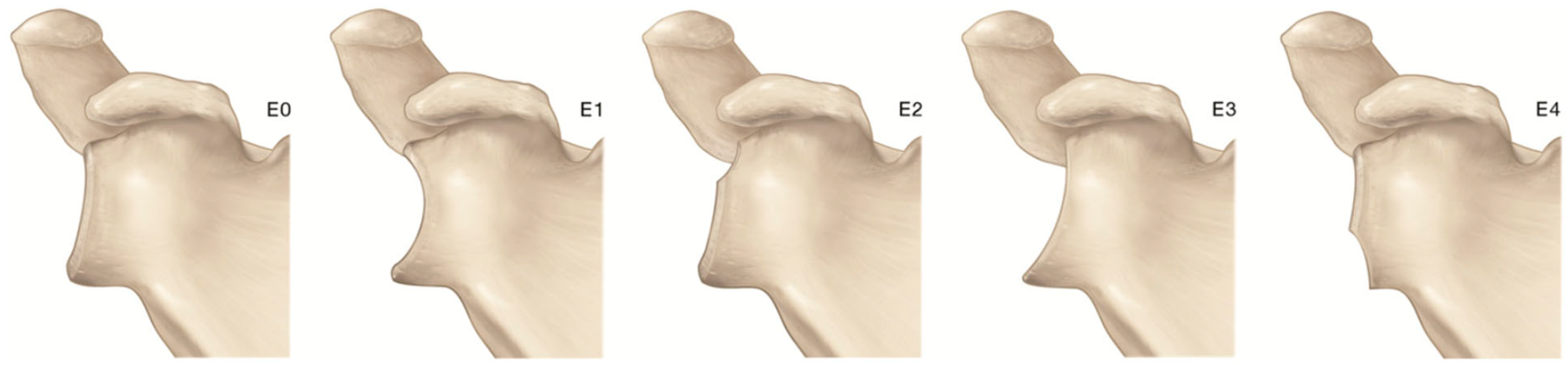
2. Gleno-Humeral Deformity in Primary Osteoarthritis and Cuff Tear Arthropathy

Degenerative changes in the glenohumeral joint are found in up to 17% of patients with shoulder pain, a patient group that has tripled in the last 40 years [11,12]. Two imaging studies using the Samilson–Prieto classification showed glenohumeral osteoarthritis (GHOA) prevalence rates in the middle-aged and elderly to be as high as 17–19%, while bilateral disease was identified in 3.1–7.7% of the population [13,14]. Prevalence rates of secondary GHOA were reported at only 1.3–1.7%, making age-related primary GHOA 10 times more common than secondary GHOA [13,14]. However, GHOA due to a specific identifiable cause has been shown to be significantly more common in patients aged less than 50 [15]. Although symptomatic GHOA is not as common as osteoarthritis of the hip and knee joints, it can be just as debilitating due to the functional importance of the upper limbs [16,17].
Etiology of GHOA is poorly understood and most of our knowledge derives from advancements made in understanding OA in general. Many theories regarding the development of GHOA were proposed, but ultimately we can consider OA a common endpoint of a heterogeneous group of disorders that lead to degenerative joint damage [18]. Academic classification of GHOA divides it into primary or idiopathic, and secondary, when a specific cause can be identified. The pathogenesis of joint damage, seen as part of a common pathological process, is influenced by multiple factors [19]. These can be divided into non-specific and specific factors as well as into systemic and local factors. Joint damage develops from the interplay between these factors, where local or systemic factors, or non-specific or specific factors, may dominate [18,20]. Disease progression is, however, typically affected by a combination of genetic, behavioral, and environmental factors [14,21,22,23,24,25].
GHOA caused by traumatic or degenerative rotator cuff tears displays three characteristic changes. These are rotator cuff insufficiency, cranial migration of the humeral head, and subsequent radiographic degenerative changes. Radiographs typically show bony erosion of the superior glenoid, resulting in acetabularization of the coracoacromial arch and rounding off of the humeral greater tuberosity [26]. Cuff tear arthropathy (CTA) is seen more commonly in women and mostly affects the shoulder of the dominant arm [17].
Primary GHOA can be classified according to Samilson and Prieto [27]. It classifies GHOA in three grades: grade 1, inferior humeral or glenoid exostosis, or both, measuring less than 3 mm in height; grade 2, inferior humeral or glenoid exostosis, or both, between 3 and 7 mm in height, with slight glenohumeral joint irregularity; and grade 3, inferior humeral or glenoid exostosis, or both, more than 7 mm in height, with narrowing of the glenohumeral joint and sclerosis. Minor modifications to this classification were proposed by Allain [28] and Gerber [29]. Another radiographic classification was developed by Guyette [30], dividing GHOA into four grades: grade 0, no appreciable signs of arthritis; grade 1, mild sclerosis and/or a small osteophyte less than 2 mm on only one side of the joint; grade 2, large marginal osteophytes or osteophytes on more than one side or surface of the joint and joint space narrowing and/or the presence of cysts; and grade 3, joint surface destruction, bone on bone, joint space narrowing, and/or loose bodies.
Classification of arthritic changes due to rotator cuff deficiency is typically performed according to Hamada et al. [31]. Their classification divides arthropathy into five grades: grade 1, AHI greater than 6 mm; grade 2, AHI 5 mm or less; grade 3, presence of acromial acetabulization; grade 4, narrowing of the glenohumeral joint along with grade 3 features; and grade 5, humeral head collapse. Afterwards, Walch et al. [32] divided the Hamada grade 4 into two subtypes: grade 4A, with narrowing of the glenohumeral joint without subacromial acetabulization, and grade 4B, with narrowing of the glenohumeral joint in the setting of subacromial acetabulization.
A more precise evaluation of glenohumeral changes, paramount in preoperative planning, requires the use of a CT scan. The basic measurement of glenoid morphology includes the inclination and the version in coronal and axial planes, respectively [33,34]. Unfortunately, these values are greatly dependent on scapular positioning and CT plain definition, resulting in measurement error [35,36]. Using a standardized position of the patient in the CT scan gantry and applying 3D-based reconstruction and planes reformatting significantly reduces measurement errors [35,37]. Walch et al. [38] developed a classification system to describe glenoid morphology in cases of primary glenohumeral osteoarthritis. Since that classification system was first presented, several authors have commented on the interobserver and intraobserver reliability of the classification, with varying results [39,40,41]. The main limitation of the original Walch classification was the use of traditional 2D CT scans, which have since been found to portray glenoid version less reliably than 3D reconstructions that analyze the scapula as a free body, as reported above [42,43,44,45]. The original classification includes five categories of glenoid patterns: A1—centered humeral head, minor erosion; A2—centered humeral head, major central glenoid erosion; B1—posterior subluxated head, no bony erosion; B2—posterior subluxated head, posterior erosion with biconcavity of the glenoid; and C—dysplastic glenoid with at least 25° of retroversion regardless of erosion [38]. Bercik et al. [46] proposed several modifications to this original classification system, suggesting the addition of the “B3” and “D” glenoids and a more precise definition of the A2 glenoid (Figure 1).
They defined the B3 glenoid as monoconcave and posteriorly worn, with at least 15° of retroversion or at least 70% posterior humeral head subluxation, or both. The B3 glenoid with posterior subluxation without significant retroversion differs from the B1 due to the presence of posterior wear. They defined the D glenoid as one with any level of glenoid anteversion or with humeral head subluxation of less than 40% (i.e., anterior subluxation). The definition of the A2 glenoid “cupula” was also updated to describe glenoids in which a line drawn from the anterior to posterior rims of the native glenoid transects the humeral head. This contrasted with the A1 glenoid, in which a line drawn from the anterior to the posterior rim of the native glenoid does not transect the humeral head. Lastly, they clarified the C glenoid to be a dysplastic glenoid with at least 25° of retroversion “not caused by erosion”. Walch classification evaluates glenoid morphology on the transverse plane, but coronal plane deformity requires assessment as well. Superior glenoid wear is common in patients with CTA and results from the progressive erosion of the glenoid by the superiorly migrated humeral head [47,48]. About 37.5% of patients with rotator-cuff-deficient shoulders had some degree of glenoid wear, and more advanced CTA has been associated with superior glenoid wear [47,49] (Figure 2).
Favard classified glenoid wear with rotator cuff tear arthritis based on the location and extent of erosion at the superior and inferior aspects of the glenoid [50]. The Favard superior glenoid wear classification system includes types E0, no glenoid wear; E1, concentric erosion of the glenoid; E2, erosion limited to the upper part of the glenoid; E3, erosion extending to the inferior part of the glenoid; and E4, erosion predominantly located at the inferior part of the glenoid (Figure 3).
Recent studies have aimed to quantify the direction and amount of glenoid erosion using 3D reconstructions of CT scans. A 3D reconstruction is crucial for planning the correction of posterior glenoid bone loss and pathologic retroversion in order to restore the native joint line [51,52]. The use of 3D CT reconstruction allowed for the identification of multiplanar glenoid deformity, and consequently the position of the implant components that prevent overmedialization of the joint line. Three-dimensional CT imaging can assist shoulder surgeons to choose between asymmetric reaming, glenoid bone grafting, and augmented glenoid components to address excessive retroversion and glenoid bone loss [53,54,55]. Otto et al. described three different patterns of multiplanar glenoid wear in type B2 biconcave glenoids [56]. They found that the most common pattern of erosion was in the posterior–central direction, with the remaining cohort falling into either the posterior–inferior or posterior–superior direction. Across all deformities, Knowles et al. reported that the line of glenoid erosion in B2 glenoids was directed toward the posterior–inferior quadrant, with the orientation of bone loss directed toward the 8 o’clock position; in addition, the radius of the curvature for the neoglenoid was flatter than the paleoglenoid [52]. Otto et al. found that the direction deviated in many cases from the 8 o’clock position [56]. Overall, this information may assist surgeons in addressing the technical factors associated with glenoid resurfacing of the B2 erosion pattern and manufacturers in the fabrication of implants that can better address commonly seen glenoid deformities.

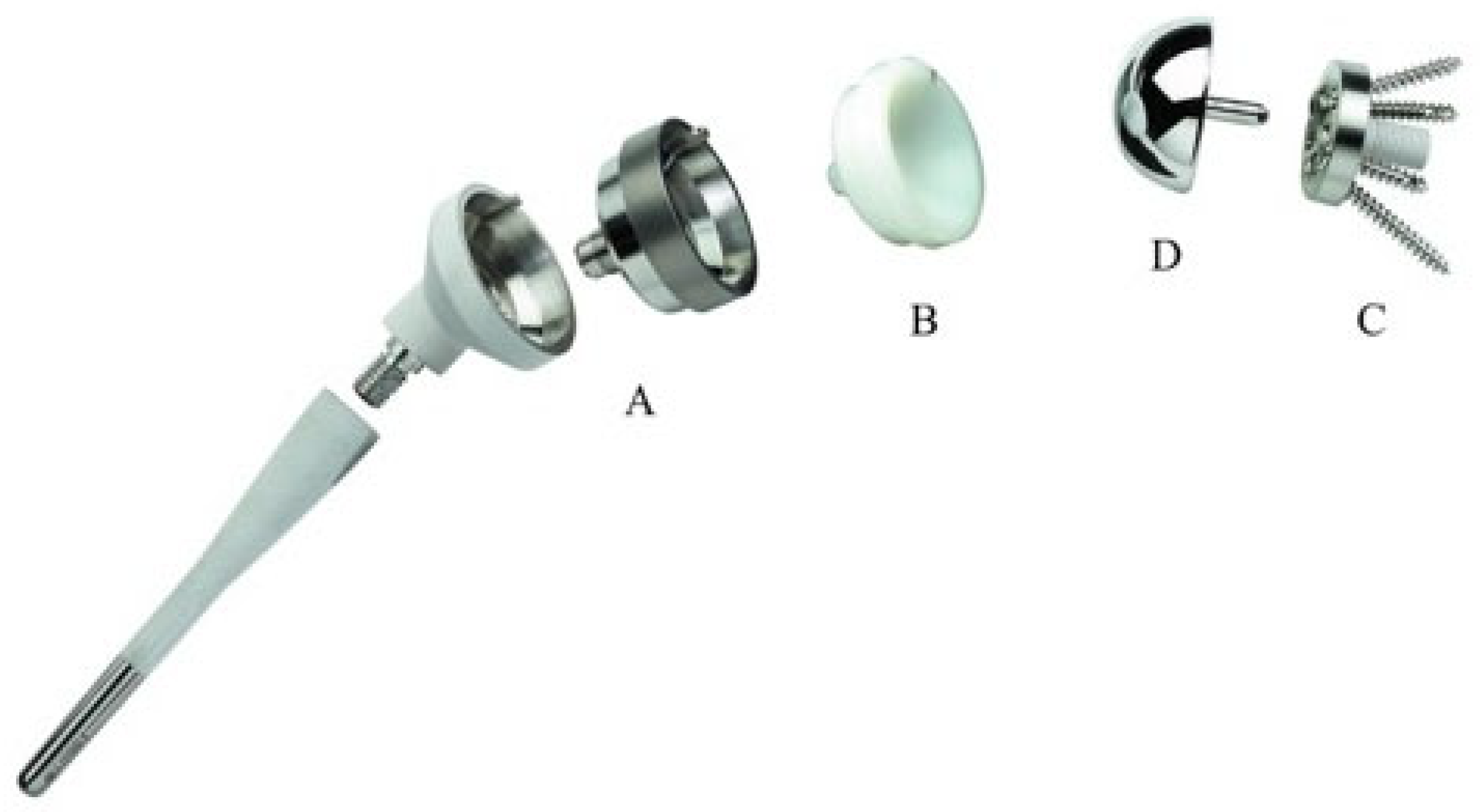
3. Biomechanics of Reverse Shoulder Arthroplasty

Grammont based its innovative reverse shoulder arthroplasty on four fundamental biomechanical principles [1,57,58]:
  • Medialization and inferiorization of the joint CoR, achieved through medialization of the glenoid and the humerus with a 145° neck–shaft angle to increase the deltoid lever arm.
  • Setting the CoR at the bone–prosthetic glenoid interface, thus reducing shear forces on the metal back.
  • Distalization of the humerus, thus tensioning the deltoid to recover strength even from the onset of the motion.
  • Semi-constrained design, obtained with a convex glenosphere and a concave humeral cup with the same curvature radius, creating a ball and socket joint and providing a stable fulcrum and ensuring static stability.
With these biomechanical adaptations, deltoid acts as a forward elevator and abductor, effectively compensating for the non-functional rotator cuff. The resultant RSA demonstrated remarkable clinical outcomes, encompassing an average active flexion of 134°, abduction of 116°, and external rotation of 36°. This was accompanied by a notable mean enhancement of the Constant score by 37 points [59] (Figure 4).
Regrettably, an overall complication rate of 9.4% was encountered [59]. Despite the satisfactory outcomes, some flaws became apparent in this design: medialization could lead to detensioning of the remaining rotator cuff [60], resulting in loosing potential strength and ROM and reducing deltoid wrapping [61]. These factors predisposed to instability [62], a primary complication with a reported incidence rate of 4% [63]. Additionally, medialization alters the contour of the shoulder [64,65] due to less offset and increased arm length [64]. Medialization also decreases anterior and posterior deltoid tension, thereby reducing rotation strength [60]. The combined effects of glenoid medialization and an increased neck–shaft angle leads to scapular notching in up to 42.5% of cases, which can ultimately result in polyethylene wear and glenoid loosening [66]. In efforts to address or mitigate these limitations, a lateralized or, to be biomechanically more accurate, less medialized design was proposed (Figure 5).
Lateralization can be achieved through the modification of the glenoid side, the humeral side, or both. Glenoid lateralization strategies include alterations in the scapular neck [67], in the baseplate [68], or in the glenosphere [69]. Lateralization at the scapular neck is obtained through the insertion of a graft between the glenoid surface and the glenoid component (Bio-RSA). The graft can be cylindrical [67] or asymmetric [53] in order to accommodate glenoid morphology and wear. A recent metanalysis [70] revealed superior results for the Bio-RSA over standard RSA in terms of the Constant score and subjective shoulder value (SSV). While improvements in range of motion (ROM) were noted in forward flexion, external rotation, and internal rotation, statistical significance in superiority was not established. Lateralization can be obtained by increasing the thickness of the glenoid implant, or by the choice of a glenosphere whose thickness is higher than its radius, namely utilizing a more-than-hemispheric design. Irrespective of the approach, the result is the lateralization of joint CoR relative to the glenoid surface. On the humeral side, lateralization can be realized by reducing the neck–shaft angle to either 145° or 135°, or by employing onlay systems or curved stems.
The lateralized RSA design has several biomechanical advantages. First, it increases tension on the remaining posterior rotator cuff tendons, resulting in enhanced external rotation strength [61]. Additionally, the lateralization of the CoR has multiple positive effects. By moving the CoR away from the scapular bony surfaces, lateralization increases the impingement-free range of motion (ROM) and reduces the risk of notching [71,72,73]. This design alteration also promotes better deltoid wrapping by shifting the deltoid force vector more medially across the humerus. This, in turn, increases joint reaction forces and enhances overall stability [61,74]. In fact, studies have reported a notable decrease in instability rates, dropping from 4.0% to 1.3% with the adoption of a lateralized design [63]. Moreover, lateralization of the CoR reduces the number of deltoid fibers situated laterally to the CoR. This has the beneficial effect of restoring the functions of anterior and posterior deltoid fibers as rotators and elevators [58]. For the same reason, this design modification helps in achieving a near-normal contour of the shoulder [58].
However, the pursuit of lateralization is not devoid of risks, despite its biomechanical advantages. Lateralization of the CoR increases stress at the glenoid bone implant interface, and the increase in stress is proportional to the amount of lateralization [75] (Figure 6).
Notably, prosthetic lateralization induced lower micromotion at the bone–implant interface compared to graft lateralization [75]. This suggests that 10 mm of prosthetic lateralization is tolerable, whereas as little as 5 mm of graft lateralization exhibited significant micromotion [75]. Furthermore, lateralization of the CoR leads to a reduction in the deltoid moment arm, increasing, as a consequence, the deltoid muscle force required for abduction [76].
A comprehensive classification of implant lateralization was devised by Werthel et al. [57]. This classification separately assessed glenoid and humeral offsets across various available implants, employing the DePuy Delta III as a reference (Figure 7).
As per this classification, a glenoid was categorized as medialized if its lateral offset deviated by less than 5 mm from that of the Delta III, and as lateralized if the offset exceeded 5 mm. Similarly, a humerus was classified as medialized if its lateral offset was less than 5 mm higher than that of the Delta III, minimally lateralized if it was 5–9 mm higher, and lateralized if it was 10–14 mm higher. By combining glenoid and humeral lateralization, a global implant lateralization categorization could be derived. Accordingly, implants were classified as medialized (global offset < 5 mm of Delta III), minimally lateralized (offset 5–10 mm of Delta III), lateralized (offset 10–15 mm of Delta III), highly lateralized (offset 15–20 mm of Delta III), and very highly lateralized (offset > 20 mm of Delta III). Commercially available implants encompassed a wide range of lateral offsets, spanning from 13.1 mm of Grammont to 35.8 mm in the most lateralized design.

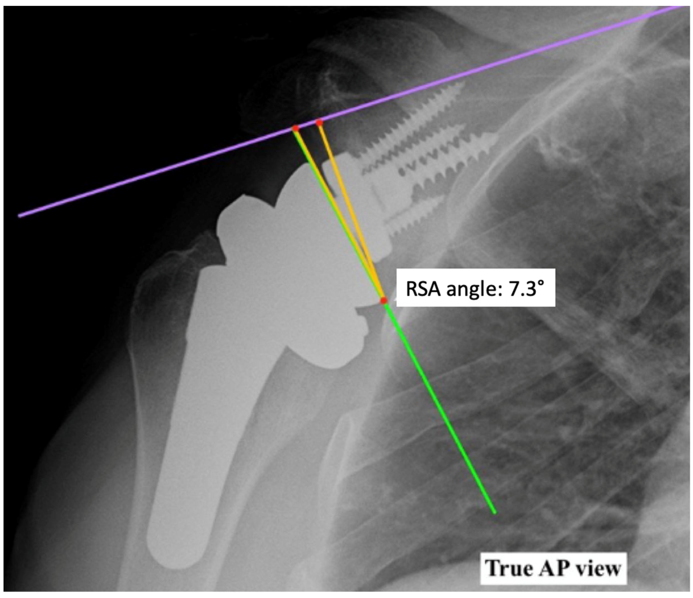
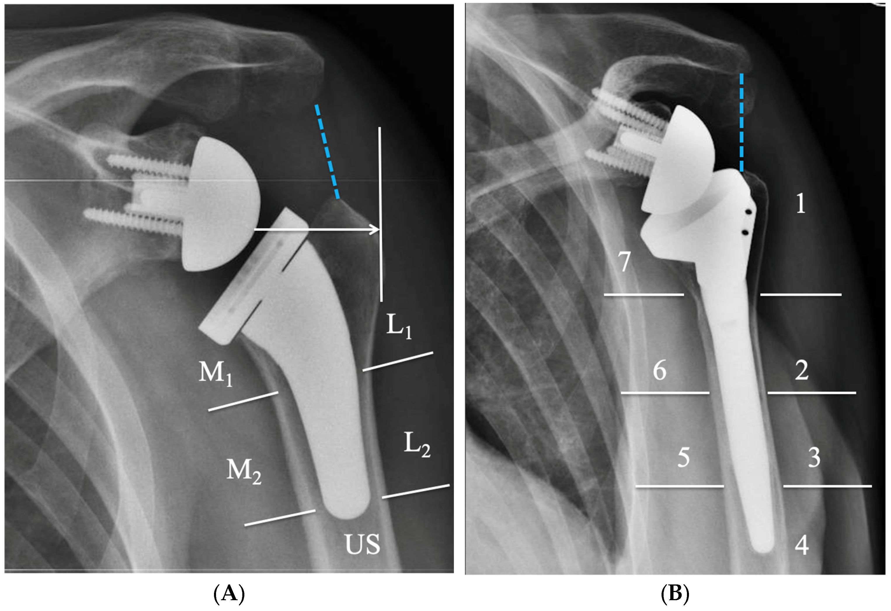
4. Radiographic Evaluation of Grammont-Style Reverse Arthroplasty

The shoulder series to evaluate the components position in RSA are fundamentally composed of two orthogonal views of the glenohumeral joint, including the entire scapula (anterior–posterior [AP] Grashey and outlet views) and axillary view [77,78,79] (Figure 8).
Humeral and glenoid components of RSA should be assessed in the early postoperative phase and at later follow-ups.
Glenoid component radiographic features include glenoid component height and tilt, scapular notching, radiolucent lines and loosening, heterotopic ossifications, and scapular fractures.
Glenoid component height is defined as the distance between the inferior edge of the baseplate and the inferior edge of the bony glenoid. It is categorized as adequate if there is an inferior overhang, high if the glenosphere grazes the inferior edge of the glenoid, and excessively high if it extends beyond [80]. Inferior offset of the glenosphere has been linked to improved outcomes [81]: inferior glenoid positioning decreases notching and increases ROM both in elevation and in rotation [71,82,83]. Glenoid inclination can be easily measured as the angle between the floor of the supraspinatus fossa and glenoid component [79]. This method, however, does not allow for an accurate evaluation of the correct implantation of an RSA. To achieve a more reproducible measurement, β-angle was proposed by Maurer et al. [84]. This is defined as the angle comprised between the floor of the supraspinatus fossa and a line connecting the upper and lower pole of the glenoid. It evaluates global glenoid inclination, not taking into account the fact that RSA is usually placed in the lower part of the glenoid, that may show a different inclination caused by wear [85]. To overcome this issue, the RSA angle was introduced (Figure 9): this is the angle defined between the perpendicular to the supraspinatus fossa line passing through the distal pole of the glenoid fossa and the line drawn from the distal pole of the glenoid fossa and the point where the supraspinatus fossa line crosses the glenoid [85]. This angle allows, on preoperative radiographs, an evaluation of the inclination of the inferior glenoid cavity and, on postoperative radiographs, to understand whether the gap has been adequately filled, ensuring correct baseplate inclination [85,86]. Adequate correction of glenoid inclination is paramount in correct RSA positioning: superior inclination is a risk factor for reduced ROM, loosening, and instability [47,87,88,89].
Scapular notching is the paramount complication of Grammont design, with an incidence of 42%. It is classified according to the Nerot–Sirveaux grading system [50] based on the size of the defect evaluated on AP X-Rays. A defect which is confined to the pillar corresponds to grade 1. In grade 2, the defect is in contact with the lower screw; in grade 3, the defect is over the lower screw; and in grade 4, it extends under the baseplate. The clinical effect of notching is still debated; while severe notching predisposes to glenoid loosening, leading to RSA failure [90], a relationship between notching and clinical outcomes was inconsistently found among different patient cohorts [91,92].
Radiolucent lines are considered as significant when >2 mm. They can be located around the screws, central peg, or baseplate [93]. Their interpretation is complicated, as their presence is not directly linked to the clinical outcome, yet they may be a sing of incipient loosening [93,94]. Loosening may be declared if the glenoid component migrated, as demonstrated by shift, tilt, or subsidence, or if complete radiolucency ≥2 mm was present in every part of the glenoid [93].
Scapular spine or acromial fracture are a relatively common complication, occurring in 2.5% of cases, and are associated with inflammatory arthritis [63]. Acromial fractures are more common than scapular spine fractures. Levy et al. [95] categorized them into three types: type I includes fractures of the midpart of the acromion, involving anterior or middle deltoid origin; type II involves the middle and a portion of the posterior deltoid origin; and type III fractures involve the entire middle and posterior glenoid origin.
Information regarding the humeral component can also be extracted. Evaluation includes stem alignment, radiographic changes around the stem, and subsidence [77].
The alignment of the prosthesis is assessed by measuring the angle between the humeral shaft axis and a line connecting the geometric center of the humeral head to the prosthesis tip. Varus or valgus alignment of the stem changes the resulting prosthetic neck–shaft angle, thus altering lateralization [96]. Stem malalignment is a common postoperative finding with short stems, with a reported prevalence of 19% [97].
Bone remodeling around the stem can be revealed by condensation lines around the tip of the stem [93], cortical thinning and osteopenia, and spot welds around the humeral component [78,93]. An assessment of the changes should be conducted both medially and laterally at one third and two thirds of the stem’s length [78] and underneath the stem [77], resulting in five measurement spots (Figure 10).
Other authors [98,99,100] divide the stem into seven zones, with two comprising the metaphyseal part, four comprising the diaphyseal part of the stem, and one surrounding the stem tip (Figure 10). Changes in these zones are summed up, and adaptations can be rated as none (0–1 changes), mild (2–3 changes), moderate (4–6 changes), or advanced (changes in every one of the five zones or changes with aggressive behavior) [77].
For short stems, the metaphyseal filling ratio can also be evaluated as the ratio between the metaphyseal stem width and metaphyseal humeral width [77].
Postoperative imaging can also provide useful information about implant stability. Many intraoperative methods are counselled for the assessment of implant stability [1,60], but the only quantitative available method is the postoperative evaluation of arm lengthening.
Pre- and postoperative assessment of the AHD allows for obtaining indirect insight into arm lengthening. This distance is measured between the most lateral part of the acromion’s undersurface and a line parallel to the top of the greater tuberosity [79,101]. Distance from the AHD line perpendicular to the most lateral portion of the greater tuberosity measures the lateral humeral offset [79,101]. An increased acromion–humeral distance correlates with improved ROM [102]. Nevertheless, arm lengthening can be evaluated using direct methods. Bilateral preoperative and postoperative true anteroposterior scaled radiographs of the humerus, taken in neutral rotation and with the patient standing, are needed. The humeral length, measured along the diaphyseal axis from the epicondylar line to the humeral head or prosthesis top, serves as a reference point. By comparing this with a line perpendicular to the diaphyseal axis passing through the most lateral and inferior acromion point, humeral lengthening can be calculated [103]. Mean humeral lengthening after arthroplasty ranges, in the literature, from 15 mm to 27, with shortening associated with increased instability [103,104]. Humeral distalization greater than 28 mm is linked to enhanced elevation and reduced notching [105].

5. Radiographic Features of Lateralized Reverse Arthroplasty

Quantitative radiographic analysis of lateralized RSA is performed using standard views previously described. Glenoid lateral offset (LO) is calculated as the sum of the radius of the glenosphere and of the CoR offset. By increasing the diameter of the glenosphere to the largest available size, glenoid lateralization increases by a mean of only 1.14 mm. This is a limited increase in lateral offset, compared with CoR lateralization or humeral lateralization [57].
LO in RSA changed significantly, passing from a mean of 13.1 mm with a medialized Grammont prosthesis up to 35.8 mm with the current design of lateralized RSA.
Changes in RSA design to achieve lateralization of the CoR have been performed through glenosphere shape modification or baseplate lateralization.
The medialized design of RSA has a resultant force vector that acts through a fixed CoR [1]. When a specific glenosphere design is created to obtain a CoR lateralization, this decreases compressive forces and increases destabilizing shear forces, creating a new moment at the glenoid–implant interface [106] (Figure 6).
When glenoid lateralization is achieved through the baseplate, the CoR falls at the baseplate–glenosphere interface, and this type of design should reduce the risk of micromotion at the glenoid bone–implant interface. Bone-increased offset RSA (BIO-RSA) was introduced as a new concept of “biologic lateralization”. In this procedure, a bone graft, obtained from the removed humeral head or from an allograft, is placed behind the glenoid component, thus thickening the scapular neck. Increasing the length of the scapular neck would lateralize both the CoR and glenoid–implant interface [67].
The CoR is maintained at the glenoid–implant interface, thus minimizing the torque on the glenoid component. Radiographic assessment of bone graft radiolucency and thickness of BIO-RSA allows us to identify bone graft healing and cases of baseplate “at risk” of loosening (radiolucent lines >2 mm).
Radiolucent lines at the interface “glenoid bone-metal” of metallic increased RSA (MIO-RSA) explain the baseplate seating (no radiolucent lines: perfect seating; radiolucent lines <2 mm: incomplete seating; and radiolucent lines >2 mm: loosening).
Radiolucent lines around the glenoid component are assessed in five zones. Additional glenoid radiographic features include scapular notching, bone scapular spurs, and ossifications [107]. Multiple radiolucent lines <2 mm or one RL ≥ 2 mm represent risk factors of glenoid component failure.
AP view is used to assess the vertical position of the glenosphere (i.e, glenosphere inferior overhang [GIO]) [108] and glenosphere inclination [84], as described in the previous sections. Insufficient GIO, following a high or flush placement of the glenosphere and a superior inclination of the baseplate (RSA > 5°), is associated with a higher risk of scapular notching. Acromio-humeral interval and lateral humeral offset provide details about the amount of humeral distalization and lateralization; furthermore, these parameters can affect deltoid tension.
Recent research findings introduced the distalization shoulder angle (DSA) and lateralization shoulder angle (LSA) as new radiographic methods to measure the inferior and lateral position of the humerus [109] (Figure 11).
The active range of motion after RSA is correlated with specific ranges of LSA and DSA. LSA between 75° and 95° is correlated with an increased active external rotation, and a DSA between 40° and 65° is correlated with increased active anterior elevation [109]. The current design of RSA allows for the performance of a lateralization on the glenoid side, humeral side, or both (global lateralization). The sum of humeral LO and glenoid LO gives global lateralization. Humeral LO is measured as the distance between the vertical line passing through the middle of the humeral stem diaphysis and the vertical line passing through the deepest point of the humeral insert surface. Glenoid LO is computed as the distance between the vertical line passing through the deepest point of the humeral insert surface and the vertical line passing through the glenoid bone–prosthesis interface [57].
The range of global lateralization achieved with an RSA implant varies from 3.3 to 20.9 mm. Current RSA devices allow for glenoid lateralization up to 7.7 with a standard baseplate and up to 8.8 mm with bone or metallic augments. The amount of glenoid lateralization required in RSA is still debated. However, surgeons are aware that they should be cautious with glenoid lateralization beyond +5–10 mm, depending on the amount of loss of medial bone stock, to avoid the risk of scapular facture or brachial plexus nerve palsy [110] (Figure 7).
Radiographic analysis of other established parameters around the humeral component includes radiolucency, condensation lines, cortical thinning, spot weld, subsidence, and resorption of the tuberosities. These radiographic features assess the stability of the humeral component and the risk of stress shielding on the cortical of the humerus.

6. Biomechanical Considerations of Lateralized Reverse Implants

Biomechanical studies of RSA showed that RSA design has effects on muscle moment arms [74].
The improved deltoid efficiency after RSA reduces the force to achieve humeral elevation. Distalization of the CoR has the effect of inducing a much larger adduction through the activity of infraspinatus and subscapularis. Offset of the humerus affects the efficiency of posterior deltoid, while a lateral CoR did not affect the muscle moment arm of external rotators [74]. These biomechanical findings confirm the efficacy of reverse design to improve deltoid lever arm when the CoR is located at the glenoid–bone interface. The use of augmented baseplate preserves glenoid bone stock in case of severe glenoid erosion [111]. Recent studies reported that an augmented baseplate preserves 54% more native bone than a nonaugmented baseplate and results in 4.1 mm of lateralization [110]. Moreover, preserving glenoid bone can prevent the risk of impingement and scapular notching.
Clinical studies demonstrated that RSA with a 135° neck–shaft angle and a lateralized glenosphere enables the better preservation of an external rotation and reduces the rate of scapular notching compared with the classic Grammont design [112]. These clinical outcomes are not in line with other biomechanical findings, demonstrating the poor effects of lateralized design on external rotators muscles [74]. Lateralization in RSA has reduced the risk of notching, almost eliminating it, but it has increased the risk of scapular spine and acromial fractures [113,114,115]. The effects of lateralized RSA on internal rotation mobility are controversial, and the results of recent clinical studies, assessing different reverse designs, are elusive.
There is substantial agreement, as confirmed by recent clinical studies, that a larger glenosphere size, a posterior offset humeral cup, and an increased inferior glenosphere overhang are associated with excellent outcomes [81].

7. Conclusions

In this study, we have explored the radiographic evaluation of RSA with a focus on lateralized designs. Our analysis revealed significant advancements over time in RSA design to enhance the biomechanical efficiency and clinical outcomes. The lateralization of the center of rotation, whether achieved through glenoid or humeral modifications, has shown improvement in deltoid function and overall patient outcomes. Additionally, radiographic parameters such as glenoid offset, humeral offset, and humeral distalization have been identified as critical indicators in assessing the success of RSA procedures. However, it is crucial to acknowledge the limitations in our understanding, including the need for standardized measurement techniques and a more comprehensive understanding of the ideal amount of lateralization. The lack of uniform measurement standards and interobserver variability in assessing radiographic parameters may introduce measurement errors and inconsistencies. Furthermore, the clinical correlation of radiographic findings and patient-reported outcomes requires further investigation to establish stronger associations.
Investigating the long-term clinical implications of lateralized RSA and its impact on patient satisfaction, function, and implant longevity is essential. Additionally, exploring novel designs and materials for RSA implants, along with their radiographic implications, will contribute to the ongoing evolution of shoulder arthroplasty techniques. Ultimately, the integration of advanced imaging modalities and computational modeling could offer a more comprehensive understanding of RSA biomechanics and guide personalized implant selection and surgical planning.

Author Contributions

Conceptualization, G.M. and G.S.; methodology, G.M. and G.S.; writing—original draft preparation, G.M., G.S., A.P., F.F., C.A.A. and M.S.; writing—review and editing, G.M. and P.P.; supervision, P.P. All authors have read and agreed to the published version of the manuscript.

Funding

This research received no external funding.

Conflicts of Interest

The authors declare no conflict of interest.

References

  1. Grammont, P.; Trouilloud, P.; Laffay, J.; Deries, X. Etude et Réalisation d’une Nouvelle Prothèse d’épaule. Rhumatologie 1987, 39, 407–418. [Google Scholar]
  2. Goetti, P.; Denard, P.J.; Collin, P.; Ibrahim, M.; Mazzolari, A.; Lädermann, A. Biomechanics of Anatomic and Reverse Shoulder Arthroplasty. EFORT Open Rev. 2021, 6, 918–931. [Google Scholar] [CrossRef] [PubMed]
  3. Berliner, J.L.; Regalado-Magdos, A.; Ma, C.B.; Feeley, B.T. Biomechanics of Reverse Total Shoulder Arthroplasty. J. Shoulder Elb. Surg. 2015, 24, 150–160. [Google Scholar] [CrossRef] [PubMed]
  4. Frankle, M.; Levy, J.C.; Pupello, D.; Siegal, S.; Saleem, A.; Mighell, M.; Vasey, M. The Reverse Shoulder Prosthesis for Glenohumeral Arthritis Associated with Severe Rotator Cuff Deficiency. A Minimum Two-Year Follow-up Study of Sixty Patients Surgical Technique. J. Bone Jt. Surg. Am. 2006, 88 Pt 2 (Suppl. 1), 178–190. [Google Scholar] [CrossRef]
  5. Tashjian, R.Z.; Hillyard, B.; Childress, V.; Kawakami, J.; Presson, A.P.; Zhang, C.; Chalmers, P.N. Outcomes after a Grammont-Style Reverse Total Shoulder Arthroplasty? J. Shoulder Elb. Surg. 2021, 30, e10–e17. [Google Scholar] [CrossRef] [PubMed]
  6. Boileau, P.; Watkinson, D.; Hatzidakis, A.M.; Hovorka, I. Neer Award 2005: The Grammont Reverse Shoulder Prosthesis: Results in Cuff Tear Arthritis, Fracture Sequelae, and Revision Arthroplasty. J. Shoulder Elb. Surg. 2006, 15, 527–540. [Google Scholar] [CrossRef] [PubMed]
  7. Rugg, C.M.; Coughlan, M.J.; Lansdown, D.A. Reverse Total Shoulder Arthroplasty: Biomechanics and Indications. Curr. Rev. Musculoskelet. Med. 2019, 12, 542–553. [Google Scholar] [CrossRef] [PubMed]
  8. Kozak, T.; Bauer, S.; Walch, G.; Al-Karawi, S.; Blakeney, W. An Update on Reverse Total Shoulder Arthroplasty: Current Indications, New Designs, Same Old Problems. EFORT Open Rev. 2021, 6, 189–201. [Google Scholar] [CrossRef]
  9. National Joint Registry. 19th Annual Report 2022; NJR: London, UK, 2022. [Google Scholar]
  10. American Academy of Orthopaedic Surgeons. Shoulder & Elbow Registry (SER): 2020 Annual Report; American Academy of Orthopaedic Surgeons (AAOS): Rosemont, IL, USA, 2021. [Google Scholar]
  11. Harkness, E.F.; Macfarlane, G.J.; Silman, A.J.; McBeth, J. Is Musculoskeletal Pain More Common Now than 40 Years Ago?: Two Population-Based Cross-Sectional Studies. Rheumatology 2005, 44, 890–895. [Google Scholar] [CrossRef]
  12. Cadogan, A.; Laslett, M.; Hing, W.A.; McNair, P.J.; Coates, M.H. A Prospective Study of Shoulder Pain in Primary Care: Prevalence of Imaged Pathology and Response to Guided Diagnostic Blocks. BMC Musculoskelet. Disord. 2011, 12, 119. [Google Scholar] [CrossRef]
  13. Oh, J.H.; Chung, S.W.; Oh, C.H.; Kim, S.H.; Park, S.J.; Kim, K.W.; Park, J.H.; Lee, S.B.; Lee, J.J. The Prevalence of Shoulder Osteoarthritis in the Elderly Korean Population: Association with Risk Factors and Function. J. Shoulder Elb. Surg. 2011, 20, 756–763. [Google Scholar] [CrossRef] [PubMed]
  14. Kobayashi, T.; Takagishi, K.; Shitara, H.; Ichinose, T.; Shimoyama, D.; Yamamoto, A.; Osawa, T.; Tajika, T. Prevalence of and Risk Factors for Shoulder Osteoarthritis in Japanese Middle-Aged and Elderly Populations. J. Shoulder Elb. Surg. 2014, 23, 613–619. [Google Scholar] [CrossRef] [PubMed]
  15. Saltzman, M.D.; Mercer, D.M.; Warme, W.J.; Bertelsen, A.L.; Matsen, F.A. Comparison of Patients Undergoing Primary Shoulder Arthroplasty before and after the Age of Fifty. J. Bone Jt. Surg. Am. 2010, 92, 42–47. [Google Scholar] [CrossRef] [PubMed]
  16. Allen, K.D.; Thoma, L.M.; Golightly, Y.M. Epidemiology of Osteoarthritis. Osteoarthr. Cartil. 2022, 30, 184–195. [Google Scholar] [CrossRef] [PubMed]
  17. Ibounig, T.; Simons, T.; Launonen, A.; Paavola, M. Glenohumeral Osteoarthritis: An Overview of Etiology and Diagnostics. Scand. J. Surg. 2021, 110, 441–451. [Google Scholar] [CrossRef] [PubMed]
  18. Dieppe, P.A.; Lohmander, L.S. Pathogenesis and Management of Pain in Osteoarthritis. Lancet 2005, 365, 965–973. [Google Scholar] [CrossRef] [PubMed]
  19. Zhang, Y.; Jordan, J.M. Epidemiology of Osteoarthritis. Clin. Geriatr. Med. 2010, 26, 355–369. [Google Scholar] [CrossRef] [PubMed]
  20. Doherty, M.; Watt, I.; Dieppe, P. Influence of Primary Generalised Osteoarthritis on Development of Secondary Osteoarthritis. Lancet 1983, 2, 8–11. [Google Scholar] [CrossRef]
  21. Fernández-Moreno, M.; Rego, I.; Carreira-Garcia, V.; Blanco, F.J. Genetics in Osteoarthritis. Curr. Genom. 2008, 9, 542–547. [Google Scholar] [CrossRef]
  22. Loughlin, J. Genetic Contribution to Osteoarthritis Development: Current State of Evidence. Curr. Opin. Rheumatol. 2015, 27, 284–288. [Google Scholar] [CrossRef]
  23. Chapman, K.; Valdes, A.M. Genetic Factors in OA Pathogenesis. Bone 2012, 51, 258–264. [Google Scholar] [CrossRef] [PubMed]
  24. Sanchez-Adams, J.; Leddy, H.A.; McNulty, A.L.; O’Conor, C.J.; Guilak, F. The Mechanobiology of Articular Cartilage: Bearing the Burden of Osteoarthritis. Curr. Rheumatol. Rep. 2014, 16, 451. [Google Scholar] [CrossRef] [PubMed]
  25. Gürer, G.; Bozbas, G.T.; Tuncer, T.; Unubol, A.I.; Ucar, U.G.; Memetoglu, O.I. Frequency of Joint Hypermobility in Turkish Patients with Knee Osteoarthritis: A Cross Sectional Multicenter Study. Int. J. Rheum. Dis. 2018, 21, 1787–1792. [Google Scholar] [CrossRef] [PubMed]
  26. Hamada, K.; Yamanaka, K.; Uchiyama, Y.; Mikasa, T.; Mikasa, M. A Radiographic Classification of Massive Rotator Cuff Tear Arthritis. Clin. Orthop. Relat. Res. 2011, 469, 2452–2460. [Google Scholar] [CrossRef] [PubMed]
  27. Samilson, R.L.; Prieto, V. Dislocation Arthropathy of the Shoulder. J. Bone Jt. Surg. Am. 1983, 65, 456–460. [Google Scholar] [CrossRef]
  28. Allain, J.; Goutallier, D.; Glorion, C. Long-Term Results of the Latarjet Procedure for the Treatment of Anterior Instability of the Shoulder. J. Bone Jt. Surg. Am. 1998, 80, 841–852. [Google Scholar] [CrossRef] [PubMed]
  29. Gerber, C.; Maquieira, G.; Espinosa, N. Latissimus Dorsi Transfer for the Treatment of Irreparable Rotator Cuff Tears. J. Bone Jt. Surg. Am. 2006, 88, 113–120. [Google Scholar] [CrossRef]
  30. Guyette, T.M.; Bae, H.; Warren, R.F.; Craig, E.; Wickiewicz, T.L. Results of Arthroscopic Subacromial Decompression in Patients with Subacromial Impingement and Glenohumeral Degenerative Joint Disease. J. Shoulder Elb. Surg. 2002, 11, 299–304. [Google Scholar] [CrossRef]
  31. Hamada, K.; Fukuda, H.; Mikasa, M.; Kobayashi, Y. Roentgenographic Findings in Massive Rotator Cuff Tears. A Long-Term Observation. Clin. Orthop. Relat. Res. 1990, 24, 92–96. [Google Scholar] [CrossRef]
  32. Walch, G.; Edwards, T.B.; Boulahia, A.; Nové-Josserand, L.; Neyton, L.; Szabo, I. Arthroscopic Tenotomy of the Long Head of the Biceps in the Treatment of Rotator Cuff Tears: Clinical and Radiographic Results of 307 Cases. J. Shoulder Elb. Surg. 2005, 14, 238–246. [Google Scholar] [CrossRef]
  33. Habermeyer, P.; Magosch, P.; Luz, V.; Lichtenberg, S. Three-Dimensional Glenoid Deformity in Patients with Osteoarthritis: A Radiographic Analysis. J. Bone Jt. Surg. Am. 2006, 88, 1301–1307. [Google Scholar] [CrossRef]
  34. Friedman, R.J.; Hawthorne, K.B.; Genez, B.M. The Use of Computerized Tomography in the Measurement of Glenoid Version. J. Bone Jt. Surg. Am. 1992, 74, 1032–1037. [Google Scholar] [CrossRef]
  35. Bryce, C.D.; Davison, A.C.; Lewis, G.S.; Wang, L.; Flemming, D.J.; Armstrong, A.D. Two-Dimensional Glenoid Version Measurements Vary with Coronal and Sagittal Scapular Rotation. J. Bone Jt. Surg. Am. 2010, 92, 692–699. [Google Scholar] [CrossRef] [PubMed]
  36. Bokor, D.J.; O’Sullivan, M.D.; Hazan, G.J. Variability of Measurement of Glenoid Version on Computed Tomography Scan. J. Shoulder Elb. Surg. 1999, 8, 595–598. [Google Scholar] [CrossRef] [PubMed]
  37. Verstraeten, T.; De Wilde, L.; Victor, J. The Normal 3D Gleno-Humeral Relationship and Anatomy of the Glenoid Planes. J. Belg. Soc. Radiol. 2018, 102, 18. [Google Scholar] [CrossRef] [PubMed]
  38. Walch, G.; Badet, R.; Boulahia, A.; Khoury, A. Morphologic Study of the Glenoid in Primary Glenohumeral Osteoarthritis. J. Arthroplast. 1999, 14, 756–760. [Google Scholar] [CrossRef] [PubMed]
  39. Kidder, J.F.; Rouleau, D.M.; DeFranco, M.J.; Pons-Villanueva, J.; Dynamidis, S. Revisited: Walch Classification of the Glenoid in Glenohumeral Osteoarthritis. Shoulder Elb. 2012, 4, 11–15. [Google Scholar] [CrossRef]
  40. Nowak, D.D.; Gardner, T.R.; Bigliani, L.U.; Levine, W.N.; Ahmad, C.S. Interobserver and Intraobserver Reliability of the Walch Classification in Primary Glenohumeral Arthritis. J. Shoulder Elb. Surg. 2010, 19, 180–183. [Google Scholar] [CrossRef] [PubMed]
  41. Scalise, J.J.; Codsi, M.J.; Brems, J.J.; Iannotti, J.P. Inter-Rater Reliability of an Arthritic Glenoid Morphology Classification System. J. Shoulder Elb. Surg. 2008, 17, 575–577. [Google Scholar] [CrossRef]
  42. Scalise, J.J.; Codsi, M.J.; Bryan, J.; Brems, J.J.; Iannotti, J.P. The Influence of Three-Dimensional Computed Tomography Images of the Shoulder in Preoperative Planning for Total Shoulder Arthroplasty. J. Bone Jt. Surg. Am. 2008, 90, 2438–2445. [Google Scholar] [CrossRef]
  43. Budge, M.D.; Lewis, G.S.; Schaefer, E.; Coquia, S.; Flemming, D.J.; Armstrong, A.D. Comparison of Standard Two-Dimensional and Three-Dimensional Corrected Glenoid Version Measurements. J. Shoulder Elb. Surg. 2011, 20, 577–583. [Google Scholar] [CrossRef]
  44. Daggett, M.; Werner, B.; Gauci, M.O.; Chaoui, J.; Walch, G. Comparison of Glenoid Inclination Angle Using Different Clinical Imaging Modalities. J. Shoulder Elb. Surg. 2016, 25, 180–185. [Google Scholar] [CrossRef] [PubMed]
  45. Kwon, Y.W.; Powell, K.A.; Yum, J.K.; Brems, J.J.; Iannotti, J.P. Use of Three-Dimensional Computed Tomography for the Analysis of the Glenoid Anatomy. J. Shoulder Elb. Surg. 2005, 14, 85–90. [Google Scholar] [CrossRef] [PubMed]
  46. Bercik, M.J.; Kruse, K.; Yalizis, M.; Gauci, M.-O.; Chaoui, J.; Walch, G. A Modification to the Walch Classification of the Glenoid in Primary Glenohumeral Osteoarthritis Using Three-Dimensional Imaging. J. Shoulder Elb. Surg. 2016, 25, 1601–1606. [Google Scholar] [CrossRef] [PubMed]
  47. Frankle, M.A.; Teramoto, A.; Luo, Z.-P.; Levy, J.C.; Pupello, D. Glenoid Morphology in Reverse Shoulder Arthroplasty: Classification and Surgical Implications. J. Shoulder Elb. Surg. 2009, 18, 874–885. [Google Scholar] [CrossRef] [PubMed]
  48. Visotsky, J.L.; Basamania, C.; Seebauer, L.; Rockwood, C.A.; Jensen, K.L. Cuff Tear Arthropathy: Pathogenesis, Classification, and Algorithm for Treatment. J. Bone Jt. Surg. Am. 2004, 86 (Suppl. 2), 35–40. [Google Scholar] [CrossRef]
  49. Klein, S.M.; Dunning, P.; Mulieri, P.; Pupello, D.; Downes, K.; Frankle, M.A. Effects of Acquired Glenoid Bone Defects on Surgical Technique and Clinical Outcomes in Reverse Shoulder Arthroplasty. J. Bone Jt. Surg. Am. 2010, 92, 1144–1154. [Google Scholar] [CrossRef]
  50. Sirveaux, F.; Favard, L.; Oudet, D.; Huquet, D.; Walch, G.; Molé, D. Grammont Inverted Total Shoulder Arthroplasty in the Treatment of Glenohumeral Osteoarthritis with Massive Rupture of the Cuff. Results of a Multicentre Study of 80 Shoulders. J. Bone Jt. Surg. Br. 2004, 86, 388–395. [Google Scholar] [CrossRef]
  51. Beuckelaers, E.; Jacxsens, M.; Van Tongel, A.; De Wilde, L.F. Three-Dimensional Computed Tomography Scan Evaluation of the Pattern of Erosion in Type B Glenoids. J. Shoulder Elb. Surg. 2014, 23, 109–116. [Google Scholar] [CrossRef]
  52. Knowles, N.K.; Keener, J.D.; Ferreira, L.M.; Athwal, G.S. Quantification of the Position, Orientation, and Surface Area of Bone Loss in Type B2 Glenoids. J. Shoulder Elb. Surg. 2015, 24, 503–510. [Google Scholar] [CrossRef]
  53. Boileau, P.; Morin-Salvo, N.; Gauci, M.-O.; Seeto, B.L.; Chalmers, P.N.; Holzer, N.; Walch, G. Angled BIO-RSA (Bony-Increased Offset-Reverse Shoulder Arthroplasty): A Solution for the Management of Glenoid Bone Loss and Erosion. J. Shoulder Elb. Surg. 2017, 26, 2133–2142. [Google Scholar] [CrossRef] [PubMed]
  54. Donohue, K.W.; Ricchetti, E.T.; Iannotti, J.P. Surgical Management of the Biconcave (B2) Glenoid. Curr. Rev. Musculoskelet. Med. 2016, 9, 30–39. [Google Scholar] [CrossRef] [PubMed]
  55. Hsu, J.E.; Ricchetti, E.T.; Huffman, G.R.; Iannotti, J.P.; Glaser, D.L. Addressing Glenoid Bone Deficiency and Asymmetric Posterior Erosion in Shoulder Arthroplasty. J. Shoulder Elb. Surg. 2013, 22, 1298–1308. [Google Scholar] [CrossRef] [PubMed]
  56. Otto, A.; Scheiderer, B.; Murphy, M.; Savino, A.; Mehl, J.; Kia, C.; Obopilwe, E.; DiVenere, J.; Cote, M.P.; Denard, P.J.; et al. Biconcave Glenoids Show 3 Differently Oriented Posterior Erosion Patterns. J. Shoulder Elb. Surg. 2021, 30, 2620–2628. [Google Scholar] [CrossRef] [PubMed]
  57. Werthel, J.-D.; Walch, G.; Vegehan, E.; Deransart, P.; Sanchez-Sotelo, J.; Valenti, P. Lateralization in Reverse Shoulder Arthroplasty: A Descriptive Analysis of Different Implants in Current Practice. Int. Orthop. 2019, 43, 2349–2360. [Google Scholar] [CrossRef]
  58. Luthringer, T.A.; Larose, G.; Kwon, Y.; Zuckerman, J.D.; Virk, M.S. Reverse Total Shoulder Arthroplasty Biomechanical Considerations and the Concept of Lateralization. Bull. Hosp. Jt. Dis. 2022, 80, 65–74. [Google Scholar]
  59. Galvin, J.W.; Kim, R.; Ment, A.; Durso, J.; Joslin, P.M.N.; Lemos, J.L.; Novikov, D.; Curry, E.J.; Alley, M.C.; Parada, S.A.; et al. Outcomes and Complications of Primary Reverse Shoulder Arthroplasty with Minimum of 2 Years’ Follow-up: A Systematic Review and Meta-Analysis. J. Shoulder Elb. Surg. 2022, 31, e534–e544. [Google Scholar] [CrossRef] [PubMed]
  60. Boileau, P.; Watkinson, D.J.; Hatzidakis, A.M.; Balg, F. Grammont Reverse Prosthesis: Design, Rationale, and Biomechanics. J. Shoulder Elb. Surg. 2005, 14, S147–S161. [Google Scholar] [CrossRef] [PubMed]
  61. Routman, H.D.; Flurin, P.-H.; Wright, T.W.; Zuckerman, J.D.; Hamilton, M.A.; Roche, C.P. Reverse Shoulder Arthroplasty Prosthesis Design Classification System. Bull. Hosp. Jt. Dis. 2015, 73 (Suppl. 1), S5–S14. [Google Scholar]
  62. Wall, B.; Nové-Josserand, L.; O’Connor, D.P.; Edwards, T.B.; Walch, G. Reverse Total Shoulder Arthroplasty: A Review of Results According to Etiology. J. Bone Jt. Surg. Am. 2007, 89, 1476–1485. [Google Scholar] [CrossRef]
  63. Shah, S.S.; Roche, A.M.; Sullivan, S.W.; Gaal, B.T.; Dalton, S.; Sharma, A.; King, J.J.; Grawe, B.M.; Namdari, S.; Lawler, M.; et al. The Modern Reverse Shoulder Arthroplasty and an Updated Systematic Review for Each Complication: Part II. JSES INTL 2021, 5, 121–137. [Google Scholar] [CrossRef]
  64. Henninger, H.B.; Barg, A.; Anderson, A.E.; Bachus, K.N.; Burks, R.T.; Tashjian, R.Z. Effect of Lateral Offset Center of Rotation in Reverse Total Shoulder Arthroplasty: A Biomechanical Study. J. Shoulder Elb. Surg. 2012, 21, 1128–1135. [Google Scholar] [CrossRef] [PubMed]
  65. Collotte, P.; Gauci, M.-O.; Vieira, T.D.; Walch, G. Bony Increased-Offset Reverse Total Shoulder Arthroplasty (BIO-RSA) Associated with an Eccentric Glenosphere and an Onlay 135° Humeral Component: Clinical and Radiological Outcomes at a Minimum 2-Year Follow-Up. JSES Int. 2022, 6, 434–441. [Google Scholar] [CrossRef]
  66. Shah, S.S.; Gaal, B.T.; Roche, A.M.; Namdari, S.; Grawe, B.M.; Lawler, M.; Dalton, S.; King, J.J.; Helmkamp, J.; Garrigues, G.E.; et al. The Modern Reverse Shoulder Arthroplasty and an Updated Systematic Review for Each Complication: Part I. JSES INTL 2020, 4, 929–943. [Google Scholar] [CrossRef] [PubMed]
  67. Boileau, P.; Moineau, G.; Roussanne, Y.; O’Shea, K. Bony Increased-Offset Reversed Shoulder Arthroplasty: Minimizing Scapular Impingement While Maximizing Glenoid Fixation. Clin. Orthop. Relat. Res. 2011, 469, 2558. [Google Scholar] [CrossRef] [PubMed]
  68. Katz, D.; Valenti, P.; Kany, J.; Elkholti, K.; Werthel, J.-D. Does Lateralisation of the Centre of Rotation in Reverse Shoulder Arthroplasty Avoid Scapular Notching? Clinical and Radiological Review of One Hundred and Forty Cases with Forty Five Months of Follow-Up. Int. Orthop. 2016, 40, 99–108. [Google Scholar] [CrossRef] [PubMed]
  69. Mulieri, P.; Dunning, P.; Klein, S.; Pupello, D.; Frankle, M. Reverse Shoulder Arthroplasty for the Treatment of Irreparable Rotator Cuff Tear without Glenohumeral Arthritis. JBJS 2010, 92, 2544. [Google Scholar] [CrossRef] [PubMed]
  70. Dimock, R.; Fathi Elabd, M.; Imam, M.; Middleton, M.; Godenèche, A.; Narvani, A.A. Bony Increased-Offset Reverse Shoulder Arthroplasty: A Meta-Analysis of the Available Evidence. Shoulder Elb. 2021, 13, 18–27. [Google Scholar] [CrossRef] [PubMed]
  71. Gutiérrez, S.; Levy, J.C.; Frankle, M.A.; Cuff, D.; Keller, T.S.; Pupello, D.R.; Lee, W.E. Evaluation of Abduction Range of Motion and Avoidance of Inferior Scapular Impingement in a Reverse Shoulder Model. J. Shoulder Elb. Surg. 2008, 17, 608–615. [Google Scholar] [CrossRef]
  72. Gutiérrez, S.; Comiskey, C.A.; Luo, Z.-P.; Pupello, D.R.; Frankle, M.A. Range of Impingement-Free Abduction and Adduction Deficit after Reverse Shoulder Arthroplasty. Hierarchy of Surgical and Implant-Design-Related Factors. J. Bone Jt. Surg. Am. 2008, 90, 2606–2615. [Google Scholar] [CrossRef]
  73. Werner, B.S.; Chaoui, J.; Walch, G. The Influence of Humeral Neck Shaft Angle and Glenoid Lateralization on Range of Motion in Reverse Shoulder Arthroplasty. J. Shoulder Elb. Surg. 2017, 26, 1726–1731. [Google Scholar] [CrossRef] [PubMed]
  74. Hamilton, M.A.; Diep, P.; Roche, C.; Flurin, P.H.; Wright, T.W.; Zuckerman, J.D.; Routman, H. Effect of Reverse Shoulder Design Philosophy on Muscle Moment Arms. J. Orthop. Res. 2015, 33, 605–613. [Google Scholar] [CrossRef] [PubMed]
  75. Denard, P.J.; Lederman, E.; Parsons, B.O.; Romeo, A.A. Finite Element Analysis of Glenoid-Sided Lateralization in Reverse Shoulder Arthroplasty. J. Orthop. Res. 2017, 35, 1548–1555. [Google Scholar] [CrossRef] [PubMed]
  76. Giles, J.W.; Langohr, G.D.G.; Johnson, J.A.; Athwal, G.S. Implant Design Variations in Reverse Total Shoulder Arthroplasty Influence the Required Deltoid Force and Resultant Joint Load. Clin. Orthop. Relat. Res. 2015, 473, 3615–3626. [Google Scholar] [CrossRef] [PubMed]
  77. Schnetzke, M.; Coda, S.; Raiss, P.; Walch, G.; Loew, M. Radiologic Bone Adaptations on a Cementless Short-Stem Shoulder Prosthesis. J. Shoulder Elb. Surg. 2016, 25, 650–657. [Google Scholar] [CrossRef] [PubMed]
  78. Nagels, J.; Stokdijk, M.; Rozing, P.M. Stress Shielding and Bone Resorption in Shoulder Arthroplasty. J. Shoulder Elb. Surg. 2003, 12, 35–39. [Google Scholar] [CrossRef] [PubMed]
  79. Berthold, D.P.; Morikawa, D.; Muench, L.N.; Baldino, J.B.; Cote, M.P.; Creighton, R.A.; Denard, P.J.; Gobezie, R.; Lederman, E.; Romeo, A.A.; et al. Negligible Correlation between Radiographic Measurements and Clinical Outcomes in Patients Following Primary Reverse Total Shoulder Arthroplasty. J. Clin. Med. 2021, 10, 809. [Google Scholar] [CrossRef] [PubMed]
  80. Lignel, A.; Berhouet, J.; Loirat, M.-A.; Collin, P.; Thomazeau, H.; Gallinet, D.; Boileau, P.; Favard, L. Reverse Shoulder Arthroplasty for Proximal Humerus Fractures: Is the Glenoid Implant Problematic? Orthop. Traumatol. Surg. Res. 2018, 104, 773–777. [Google Scholar] [CrossRef]
  81. Haidamous, G.; Lädermann, A.; Hartzler, R.U.; Parsons, B.O.; Lederman, E.S.; Tokish, J.M.; Denard, P.J. Radiographic Parameters Associated with Excellent versus Poor Range of Motion Outcomes Following Reverse Shoulder Arthroplasty. Shoulder Elb. 2022, 14, 39–47. [Google Scholar] [CrossRef]
  82. Nyffeler, R.W.; Werner, C.M.L.; Gerber, C. Biomechanical Relevance of Glenoid Component Positioning in the Reverse Delta III Total Shoulder Prosthesis. J. Shoulder Elb. Surg. 2005, 14, 524–528. [Google Scholar] [CrossRef]
  83. Li, X.; Dines, J.S.; Warren, R.F.; Craig, E.V.; Dines, D.M. Inferior Glenosphere Placement Reduces Scapular Notching in Reverse Total Shoulder Arthroplasty. Orthopedics 2015, 38, e88–e93. [Google Scholar] [CrossRef] [PubMed]
  84. Maurer, A.; Fucentese, S.F.; Pfirrmann, C.W.A.; Wirth, S.H.; Djahangiri, A.; Jost, B.; Gerber, C. Assessment of Glenoid Inclination on Routine Clinical Radiographs and Computed Tomography Examinations of the Shoulder. J. Shoulder Elb. Surg. 2012, 21, 1096–1103. [Google Scholar] [CrossRef] [PubMed]
  85. Boileau, P.; Gauci, M.-O.; Wagner, E.R.; Clowez, G.; Chaoui, J.; Chelli, M.; Walch, G. The Reverse Shoulder Arthroplasty Angle: A New Measurement of Glenoid Inclination for Reverse Shoulder Arthroplasty. J. Shoulder Elb. Surg. 2019, 28, 1281–1290. [Google Scholar] [CrossRef] [PubMed]
  86. Werthel, J.-D.; Villard, A.; Kazum, E.; Deransart, P.; Ramirez, O. Accuracy of Reverse Shoulder Arthroplasty Angle According to the Size of the Baseplate. J. Shoulder Elb. Surg. 2023, 32, 310–317. [Google Scholar] [CrossRef] [PubMed]
  87. Falaise, V.; Levigne, C.; Favard, L. Scapular Notching in Reverse Shoulder Arthroplasties: The Influence of Glenometaphyseal Angle. Orthop. Traumatol. Surg. Res. 2011, 97, S131–S137. [Google Scholar] [CrossRef] [PubMed]
  88. Gutiérrez, S.; Walker, M.; Willis, M.; Pupello, D.R.; Frankle, M.A. Effects of Tilt and Glenosphere Eccentricity on Baseplate/Bone Interface Forces in a Computational Model, Validated by a Mechanical Model, of Reverse Shoulder Arthroplasty. J. Shoulder Elb. Surg. 2011, 20, 732–739. [Google Scholar] [CrossRef]
  89. Laver, L.; Garrigues, G.E. Avoiding Superior Tilt in Reverse Shoulder Arthroplasty: A Review of the Literature and Technical Recommendations. J. Shoulder Elb. Surg. 2014, 23, 1582–1590. [Google Scholar] [CrossRef] [PubMed]
  90. Roche, C.P.; Stroud, N.J.; Martin, B.L.; Steiler, C.A.; Flurin, P.-H.; Wright, T.W.; DiPaola, M.J.; Zuckerman, J.D. The Impact of Scapular Notching on Reverse Shoulder Glenoid Fixation. J. Shoulder Elb. Surg. 2013, 22, 963–970. [Google Scholar] [CrossRef]
  91. Mollon, B.; Mahure, S.A.; Roche, C.P.; Zuckerman, J.D. Impact of Scapular Notching on Clinical Outcomes after Reverse Total Shoulder Arthroplasty: An Analysis of 476 Shoulders. J. Shoulder Elb. Surg. 2017, 26, 1253–1261. [Google Scholar] [CrossRef]
  92. Lévigne, C.; Garret, J.; Boileau, P.; Alami, G.; Favard, L.; Walch, G. Scapular Notching in Reverse Shoulder Arthroplasty: Is It Important to Avoid It and How? Clin. Orthop. Relat. Res. 2011, 469, 2512. [Google Scholar] [CrossRef]
  93. Melis, B.; DeFranco, M.; Lädermann, A.; Molé, D.; Favard, L.; Nérot, C.; Maynou, C.; Walch, G. An Evaluation of the Radiological Changes around the Grammont Reverse Geometry Shoulder Arthroplasty after Eight to 12 Years. J. Bone Jt. Surg. Br. 2011, 93, 1240–1246. [Google Scholar] [CrossRef] [PubMed]
  94. Lopiz, Y.; Galán-Olleros, M.; Rodriguez-Rodriguez, L.; García-Fernández, C.; Marco, F. Radiographic Changes around the Glenoid Component in Primary Reverse Shoulder Arthroplasty at Mid-Term Follow-Up. J. Shoulder Elb. Surg. 2021, 30, e378–e391. [Google Scholar] [CrossRef] [PubMed]
  95. Levy, J.C.; Anderson, C.; Samson, A. Classification of Postoperative Acromial Fractures Following Reverse Shoulder Arthroplasty. J. Bone Jt. Surg. Am. 2013, 95, e104. [Google Scholar] [CrossRef] [PubMed]
  96. Lädermann, A.; Chiu, J.C.-H.; Cunningham, G.; Hervé, A.; Piotton, S.; Bothorel, H.; Collin, P. Do Short Stems Influence the Cervico-Diaphyseal Angle and the Medullary Filling after Reverse Shoulder Arthroplasties? Orthop. Traumatol. Surg. Res. 2020, 106, 241–246. [Google Scholar] [CrossRef] [PubMed]
  97. Tross, A.K.; Woolson, T.E.; Nolte, P.C.; Schnetzke, M.; Loew, M.; Millett, P.J. Primary Reverse Shoulder Replacement with a Short Stem: A Systematic Literature Review. JSES Rev. Rep. Tech. 2021, 1, 7–16. [Google Scholar] [CrossRef] [PubMed]
  98. Harmsen, S.M.; Norris, T.R. Radiographic Changes and Clinical Outcomes Associated with an Adjustable Diaphyseal Press-Fit Humeral Stem in Primary Reverse Shoulder Arthroplasty. J. Shoulder Elb. Surg. 2017, 26, 1589–1597. [Google Scholar] [CrossRef] [PubMed]
  99. Sanchez-Sotelo, J.; Wright, T.W.; O’Driscoll, S.W.; Cofield, R.H.; Rowland, C.M. Radiographic Assessment of Uncemented Humeral Components in Total Shoulder Arthroplasty. J. Arthroplast. 2001, 16, 180–187. [Google Scholar] [CrossRef]
  100. Sperling, J.W.; Cofield, R.H.; O’Driscoll, S.W.; Torchia, M.E.; Rowland, C.M. Radiographic Assessment of Ingrowth Total Shoulder Arthroplasty. J. Shoulder Elb. Surg. 2000, 9, 507–513. [Google Scholar] [CrossRef]
  101. Werner, B.S.; Jacquot, A.; Molé, D.; Walch, G. Is Radiographic Measurement of Acromiohumeral Distance on Anteroposterior View after Reverse Shoulder Arthroplasty Reliable? J. Shoulder Elb. Surg. 2016, 25, e276–e280. [Google Scholar] [CrossRef]
  102. Kim, D.-H.; Choi, H.-U.; Choi, B.-C.; Kim, J.-H.; Cho, C.-H. Postoperative Acromiohumeral Interval Affects Shoulder Range of Motions Following Reverse Total Shoulder Arthroplasty. Sci. Rep. 2022, 12, 21011. [Google Scholar] [CrossRef]
  103. Lädermann, A.; Williams, M.D.; Melis, B.; Hoffmeyer, P.; Walch, G. Objective Evaluation of Lengthening in Reverse Shoulder Arthroplasty. J. Shoulder Elb. Surg. 2009, 18, 588–595. [Google Scholar] [CrossRef] [PubMed]
  104. Lädermann, A.; Edwards, T.B.; Walch, G. Arm Lengthening after Reverse Shoulder Arthroplasty: A Review. Int. Orthop. 2014, 38, 991–1000. [Google Scholar] [CrossRef] [PubMed]
  105. Ferrier, A.; Blasco, L.; Marcoin, A.; De Boissieu, P.; Siboni, R.; Nérot, C.; Ohl, X. Geometric Modification of the Humeral Position after Total Reverse Shoulder Arthroplasty: What Is the Optimal Lowering of the Humerus? J. Shoulder Elb. Surg. 2018, 27, 2207–2213. [Google Scholar] [CrossRef]
  106. Harman, M.; Frankle, M.; Vasey, M.; Banks, S. Initial Glenoid Component Fixation in “Reverse” Total Shoulder Arthroplasty: A Biomechanical Evaluation. J. Shoulder Elb. Surg. 2005, 14, S162–S167. [Google Scholar] [CrossRef] [PubMed]
  107. Matsen, F.A.; Iannotti, J.P.; Churchill, R.S.; De Wilde, L.; Edwards, T.B.; Evans, M.C.; Fehringer, E.V.; Groh, G.I.; Kelly, J.D.; Kilian, C.M.; et al. One and Two-Year Clinical Outcomes for a Polyethylene Glenoid with a Fluted Peg: One Thousand Two Hundred Seventy Individual Patients from Eleven Centers. Int. Orthop. 2019, 43, 367–378. [Google Scholar] [CrossRef] [PubMed]
  108. Boileau, P.; Morin-Salvo, N.; Bessière, C.; Chelli, M.; Gauci, M.-O.; Lemmex, D.B. Bony Increased-Offset-Reverse Shoulder Arthroplasty: 5 to 10 Years’ Follow-Up. J. Shoulder Elb. Surg. 2020, 29, 2111–2122. [Google Scholar] [CrossRef] [PubMed]
  109. Boutsiadis, A.; Lenoir, H.; Denard, P.J.; Panisset, J.-C.; Brossard, P.; Delsol, P.; Guichard, F.; Barth, J. The Lateralization and Distalization Shoulder Angles Are Important Determinants of Clinical Outcomes in Reverse Shoulder Arthroplasty. J. Shoulder Elb. Surg. 2018, 27, 1226–1234. [Google Scholar] [CrossRef] [PubMed]
  110. Bauer, S.; Corbaz, J.; Athwal, G.S.; Walch, G.; Blakeney, W.G. Lateralization in Reverse Shoulder Arthroplasty. J. Clin. Med. 2021, 10, 5380. [Google Scholar] [CrossRef]
  111. Slowinski, J.J.; Bauer, J.A.; Feng, L.; Schoch, N.; Sperling, J.W.; Duquin, T.R. Computed Tomography–Based Three-Dimensional Modeling of Glenoid Bone Preservation with Augmented Baseplates. Semin. Arthroplast. JSES 2023, 33, 162–168. [Google Scholar] [CrossRef]
  112. Freislederer, F.; Toft, F.; Audigé, L.; Marzel, A.; Endell, D.; Scheibel, M. Lateralized vs. Classic Grammont-Style Reverse Shoulder Arthroplasty for Cuff Deficiency Hamada Stage 1–3: Does the Design Make a Difference? J. Shoulder Elb. Surg. 2022, 31, 341–351. [Google Scholar] [CrossRef]
  113. Merolla, G.; Walch, G.; Ascione, F.; Paladini, P.; Fabbri, E.; Padolino, A.; Porcellini, G. Grammont Humeral Design versus Onlay Curved-Stem Reverse Shoulder Arthroplasty: Comparison of Clinical and Radiographic Outcomes with Minimum 2-Year Follow-Up. J. Shoulder Elb. Surg. 2018, 27, 701–710. [Google Scholar] [CrossRef]
  114. Lawrence, C.; Williams, G.R.; Namdari, S. Influence of Glenosphere Design on Outcomes and Complications of Reverse Arthroplasty: A Systematic Review. Clin. Orthop. Surg. 2016, 8, 288–297. [Google Scholar] [CrossRef]
  115. Mahendraraj, K.A.; Abboud, J.; Armstrong, A.; Austin, L.; Brolin, T.; Entezari, V.; Friedman, L.; Garrigues, G.E.; Grawe, B.; et al.; ASES Complications of RSA Research Group Predictors of Acromial and Scapular Stress Fracture after Reverse Shoulder Arthroplasty: A Study by the ASES Complications of RSA Multicenter Research Group. J. Shoulder Elb. Surg. 2021, 30, 2296–2305. [Google Scholar] [CrossRef]
Figure 1. Representation of glenoid morphology in osteoarthritis according to Walch et al. as modified by Bercik et al. [46].
Prosthesis 05 00075 g001
Figure 2. Superior migration of the humeral head in CTA.
Prosthesis 05 00075 g002
Figure 3. Representation of glenoid wear in cuff tear arthritis according to Favard et al. [50].
Prosthesis 05 00075 g003
Figure 4. Grammont reverse design of shoulder arthroplasty. The humeral component included: (A) a distal stem with a metaphysis and an optional humeral spacer; (B) a centered (standard) and retentive constrained humeral insert, with variable height (+6 mm, +9 mm, and +12 mm). The glenoid component included: (C) a hydroxyapatite-coated baseplate (25 and 29 mm) with a central post and 4 self-tapping screws (2 compression screws and 2 multidirectional locking screws), and (D) centered and eccentric (+2 mm and +4 mm) glenospheres (Stryker, Kalamazoo, MI, USA).
Prosthesis 05 00075 g004
Figure 5. Short-stem lateralized humeral component of reverse shoulder arthroplasty. (A) A hydroxyapatite-coated curved short-stem 132.5° inclination; (B) an eccentric (+1.5 mm and +3.5 mm) reverse tray; and (C) an asymmetric polyethylene insert (thickness + 6 mm and + 9 mm) with 12.5° inclination (Stryker, Kalamazoo, MI, USA).
Prosthesis 05 00075 g005
Figure 6. RSA acting with a fixed CoR with compressive (Fc) and shear (Fs) components of the resultant force vector (Fv). B. CoR lateralization increases the lever arm length which decreases compressive forces, increases destabilizing shear forces, and creates a new moment (M) at the glenoid–implant interface [3]. RSA: reverse shoulder arthroplasty; CoR: center of rotation.
Prosthesis 05 00075 g006
Figure 7. Radiographic references to measure humeral and glenoid offset in lateralized RSA (global lateral offset), as described by Werthel et al. [19]. Line A is the vertical line passing through the middle of the diaphysis of the humeral stem. Line B is the horizontal line passing through the middle of the surface of the humeral implant at the level of the humeral cut. Line C is the vertical line passing through the “pivot point” defined as the deepest point of the articular surface of the humeral insert measured perpendicular to the surface of the humeral insert. Line D is the vertical line passing through the center of rotation of the joint. Line E is the vertical line passing through the bone–glenoid baseplate interface. Humeral lateral offset (distance AC) was defined as the sum of the humeral stem offset (distance AB) and of the humeral insert offset (distance BC). Glenoid lateral offset (distance CE) was defined as the sum of the “perceived radius of the glenosphere” (distance CD) and of the center of rotation offset (distance DE).
Prosthesis 05 00075 g007
Figure 8. Standard radiograph series to assess the shoulder joint. (A) True AP view, (B) outlet view, (C) axillary view. AP: anterior–posterior.
Prosthesis 05 00075 g008
Figure 9. The RSA angle is the angle between the inferior part of the glenoid fossa (where the baseplate is implanted) and the perpendicular to the floor of the supraspinatus fossa.
Prosthesis 05 00075 g009
Figure 10. Anterior–posterior Grashey view of the 2 reverse prostheses. (A) Onlay curved short-stem design. (B) Medialized standard-stem design (Grammont design). The curved-stem design increases the humeral offset (white arrow), whereas the acromiohumeral interval (dotted lines) remains unchanged if the humeral tray is placed below the greater tuberosity. Humeral bone remodeling and radiolucency can be assessed in 5 zones of the short stem and in 7 zones of the standard straight stem. M1, medial 1; M2, medial 2; L1, lateral 1; L2, lateral 2; US, under stem.
Prosthesis 05 00075 g010
Figure 11. Distalization shoulder angle (DSA) (A) and lateralization shoulder angle (LSA) (B).
Prosthesis 05 00075 g011
Disclaimer/Publisher’s Note: The statements, opinions and data contained in all publications are solely those of the individual author(s) and contributor(s) and not of MDPI and/or the editor(s). MDPI and/or the editor(s) disclaim responsibility for any injury to people or property resulting from any ideas, methods, instructions or products referred to in the content.

