Abstract
Background/Objectives: A cam-driven hydraulic prosthetic ankle was designed to overcome the weaknesses of commercial prostheses and research prototypes, which largely fail to mimic the energy-recycling behaviour of an intact ankle, resulting in poor walking performance for lower-limb prosthesis users. Methods: This novel device exploits miniature hydraulics to capture the negative work performed during stance, prior to push-off, in a hydraulic accumulator, and return positive work during push-off for forward body propulsion. Two cams are used to replicate intact ankle torque profiles based on experimental data. The design process for the new prosthesis used a design programme, implemented in MATLAB, based on a simulation of the main components of the prosthetic ankle. Results: In this paper, we present the design programme and explain how it is used to determine the cam profiles required to replicate intact ankle torque, as well as to size the cam follower return springs. Moreover, a constraint-based preliminary design investigation is described, which was conducted to size other key components affecting the device’s size, performance, and energy efficiency. Finally, the feasible design alternatives are compared in terms of their energy losses to determine the best design with regard to minimising both energy losses and device size. Conclusions: Such a design approach not only documents the design of a particular novel prosthetic ankle, but can also provide a systematic framework for decomposing complex design challenges into a series of sub-problems, providing a more effective alternative to heuristic approaches in prosthetic design.
Keywords:
prosthetics; prosthetic ankle; prosthetic foot; simulation; computational modelling; design; hydraulics; cam 1. Introduction
Individuals with lower-limb amputations still face daily challenges due to the limited performance of commercial passive (i.e., unpowered) prosthetic feet—whether energy storage and return (ESR) or conventional prostheses [1]—which still falls short of the human foot functionality. In particular, a major problem is that they cannot generate the plantarflexion moment required during push-off for forward propulsion, failing to emulate the missing plantarflexion musculature, leading to a consequent decrease in push-off power generation. Push-off power peak values for passive prostheses are, indeed, generally less than half those measured in healthy subjects, which are usually between and W/kg [2,3]. As a result, prosthesis users typically exhibit gait asymmetries due to compensatory strategies, leading to higher energy consumption when compared to healthy subjects [4,5,6,7].
Over the last two decades, many research efforts have been made to better replicate the anatomically intact ankle’s energy storage and release mechanism and/or its torque-versus-angle curve, through both powered and unpowered designs. A well-known active (i.e., powered) prosthetic foot that has reached the market is the Ottobock Empower, which can actively generate power during push-off. However, although push-off is improved, its energy recycling performance is no better than passive carbon fibre ESR prosthetic feet [8]. In addition, active designs show limitations related to the use of batteries and electric motors, including increased weight, size, and cost, as well as reduced user autonomy [9]. These limitations are compounded by a lower acceptance rate due to the complex control architectures that increase the cognitive load on the user [10].
Active and passive ESR concepts can mainly be classified as clutch-and-spring or hydraulic prostheses [11]. The former are usually complex designs that provide discrete, non-biomimetic control of the ankle joint, and are often large and heavy. Hydraulics is used in commercial prostheses mainly for damping, and for ground and speed adaptation purposes, as seen in the Meridium and Triton Smart Ankles (Ottobock), the Elan (Blatchford), and the Freedom Kinnex 2.0 (Proteor). Some active research designs, including electrohydrostatic or electrically powered hydraulic actuators, can actively power push-off and generate biomimetic ankle torques, but are also often large and heavy [11].
Nevertheless, as opposed to clutch-and-spring concepts, hydraulics is well suited to both providing biomimetic ankle torques and storing and returning energy over the gait cycle by including a hydraulic accumulator. For active devices, this should lead to smaller actuators and batteries. Furthermore, hydraulics is also well suited to miniaturisation (due to high power densities).
Therefore, driven by the desire to improve the quality of life of lower-limb prosthesis users, and aware of the increasing number of people living with a lower-limb amputation, mainly because of vascular diseases [12], we designed a novel prosthetic ankle (Figure 1) that exploits the advantages of hydraulics and uses an accumulator for recycling energy at the ankle joint [11]. In addition, it provides biomimetic ankle joint torques by including two cam-driven rams.

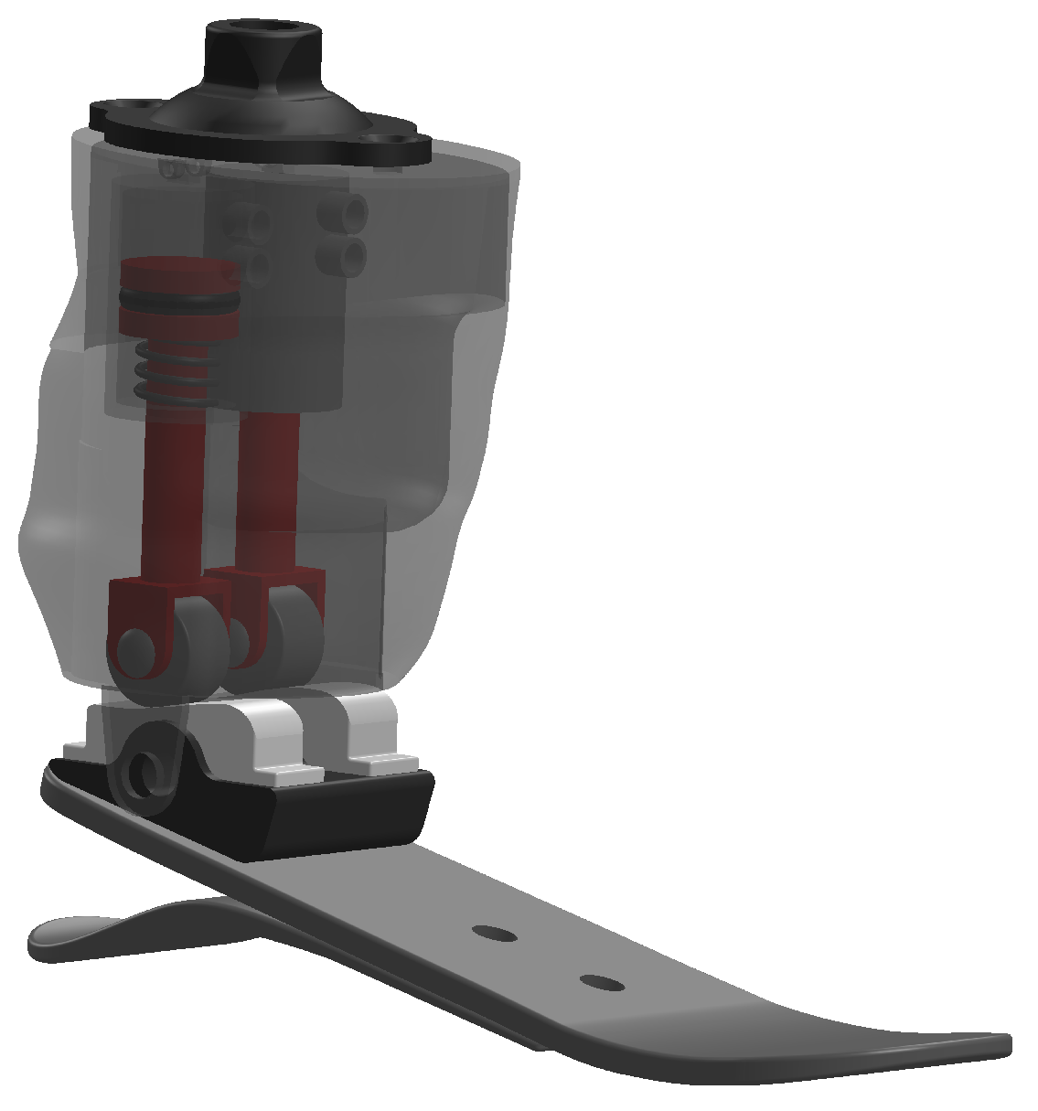
Figure 1.
The new hydraulic ankle prosthesis described in [11,13]: a solid model including the main components (cams, rollers, followers, rams) and a foot consisting of two carbon fibre laminates.
Via a gearbox, the prosthetic ankle joint drives a camshaft on which two cams are mounted and, in turn, these drive two miniature hydraulic rams. The “stance cam-ram system” stores the eccentric (negative) work performed during mid-stance (i.e., from foot flat until ankle maximum dorsiflexion) by pumping oil into the accumulator, while the “push-off system” performs concentric (positive) work during push-off (i.e., from ankle maximum dorsiflexion to maximum plantarflexion) through fluid flowing from the accumulator to the ram, providing forward propulsion. Each ram is connected to a tank during load acceptance (i.e., from heel strike to foot flat) and swing, as well as during the working phase of the other ram (i.e., push-off for the stance cam-ram system, and mid-stance for the push-off cam-ram system). A detailed description of the design can be found in [11,13].
The performance of the new design was assessed using a simulation model, implemented in MATLAB, which simulates the operation of the new device over the whole gait cycle (results reported in [11]). The results show that the prosthesis can replicate the torque of an intact ankle during the working phases of the two cam-ram systems. Moreover, of the total eccentric work stored by the prosthetic ankle during one gait cycle (i.e., the energy input) is returned as concentric work, primarily during push-off; 14% is stored in the accumulator and can power future gait cycles; and 8% is lost. Furthermore, the main components of the system, which were sized using a simulation-based design programme, are physically realistic and the prosthesis matches the size and mass of the missing anatomy [11].
In this paper, we describe in detail the simulation-based design programme, which was implemented in MATLAB. MATLAB is a commercial programming and numeric computing environment widely used in the scientific community due to its computing capabilities for simulation and modelling. Moreover, simulations represent an effective way to virtually test and optimize designs, reducing development time and the costs and risks associated with physical prototyping, although their reliability depends on the model accuracy and the assumptions used. The design programme we present uses the aforementioned simulation model to design the cam profiles, such that they generate the required intact ankle torque profiles, and also the cam follower return springs. We also describe our preliminary design investigation, which used the aforementioned design programme to specify other key components based on two design objectives, namely minimising energy losses and keeping the device size acceptably small.
We believe that such a design programme can provide a systematic framework to decompose complex design challenges into manageable sub-problems, while basing the process on a rigorous analysis of the mechanical design of the system and its dynamics.
2. Materials and Methods
The novelty of the new design lies in the use of a hydraulic accumulator to store and return energy, and cam-driven hydraulic rams to provide biomimetic ankle torques. The two cam profiles are designed to replicate the torque-versus-angle curve of the ankle joint of a healthy subject. This was achieved using a design programme implemented in MATLAB (R2018b, The MathWorks, Inc., Natick, MA, USA), which incorporates a simulation of the whole system over the whole gait cycle based on a detailed mathematical model including all significant sources of energy loss. As well as calculating the two cam profiles, the design programme also sizes the two cam-follower return springs to ensure continuous contact between each cam and the corresponding roller-follower. The design programme was used in a preliminary design investigation and, to simplify the process, the design parameters were classified as primary and secondary independent variables, dependent variables, and constants. This classification enabled a sequential design process whereby the design variables were assigned in order of importance and, at each stage, the subset of feasible designs was reduced until, finally, the best design was identified, which is the one described in [11].
The following subsections describe the simulation-based design programme; the classification of the design parameters; and the preliminary design investigation.
2.1. Simulation-Based Design Programme
The MATLAB design programme uses an iterative approach with three nested loops: an outer loop to size the cam follower return springs; a middle loop to determine the cam profiles; and an inner time-stepping loop to model the states of the valves, the dynamics of the cam-ram systems, and the filling and emptying of the accumulator. In other words, the inner loop simulates the whole system over one gait cycle, and the two outer loops automate two aspects of the design process.
The middle loop converges iteratively to calculate the two cam profiles that enable the system to match the ankle torque versus angle curve of an intact ankle (from in vivo experimental data [14]), during the working phases of the two cam-rams. Iterations are necessary to calculate the two cam profiles because the total camshaft torque (sum of the two cam torques) is determined by the dynamics of the two cam-rams, which are in turn based on velocities and accelerations that depend upon the cam profiles (so there is a circular dependency). In other words, simulation over the gait cycle requires a priori knowledge of the cam profiles. Consequently, an initial estimate of the two cam profiles is used to run the simulation model and calculate the actual camshaft torque curves in the two working phases. The error between the required and the actual (i.e., calculated) torques is, in turn, used in the following iteration to update the cam profiles. The iteration loop is repeated until the error is negligible over the two working phases. Therefore, the calculation of the cam profiles is described below under the two following headings.
2.1.1. Estimating an Initial Cam Profile
The method for estimating an initial cam profile is the same for both cam-ram systems, so it is explained for the stance cam-ram only. The purpose of each cam profile is to define the ratio of piston incremental displacement to cam incremental angle () as a function of cam rotation angle . All friction terms were neglected for this initial estimate, as well as the torque generated by the non-working cam-ram that is connected to a tank. Therefore, it can be assumed that, during its working phase, the stance cam torque () equals the required camshaft torque (), and the work performed by the stance cam is equal to the work performed by the piston on the hydraulic fluid:
By rearranging Equation (1), the initial estimate of during the stance cam’s working phase is
where neglecting the piston O-ring friction causes the hydraulic ram force to be the product of the gauge cylinder pressure and piston area (, with because all friction terms between the cylinder and accumulator (i.e., pipes, fittings, valve) are neglected, and ).
The cam profile is also followed during the non-working phase, i.e., when the ram is connected to a tank. So, for cam angles within the working range, the ratios in the non-working phase are determined by the interpolation of the working phase results. For cam angles outside of the working range, a constant cam radius is required to avoid unnecessary piston displacement in the non-working phase and hence minimise friction losses. For this reason, the ratio is set to zero for cam angles outside the range seen during the working phase.
Consequently, the overall piston displacement (y) is evaluated by cumulatively summing the incremental changes , with (see Figure 2), and this is used to calculate the cam profile. Specifically, the profile is obtained by connecting the contact points P between the cam and roller, whose coordinates are evaluated in the cam frame as follows (refer to Figure 3 and Table A1 for the nomenclature, and to [13] for a full explanation):

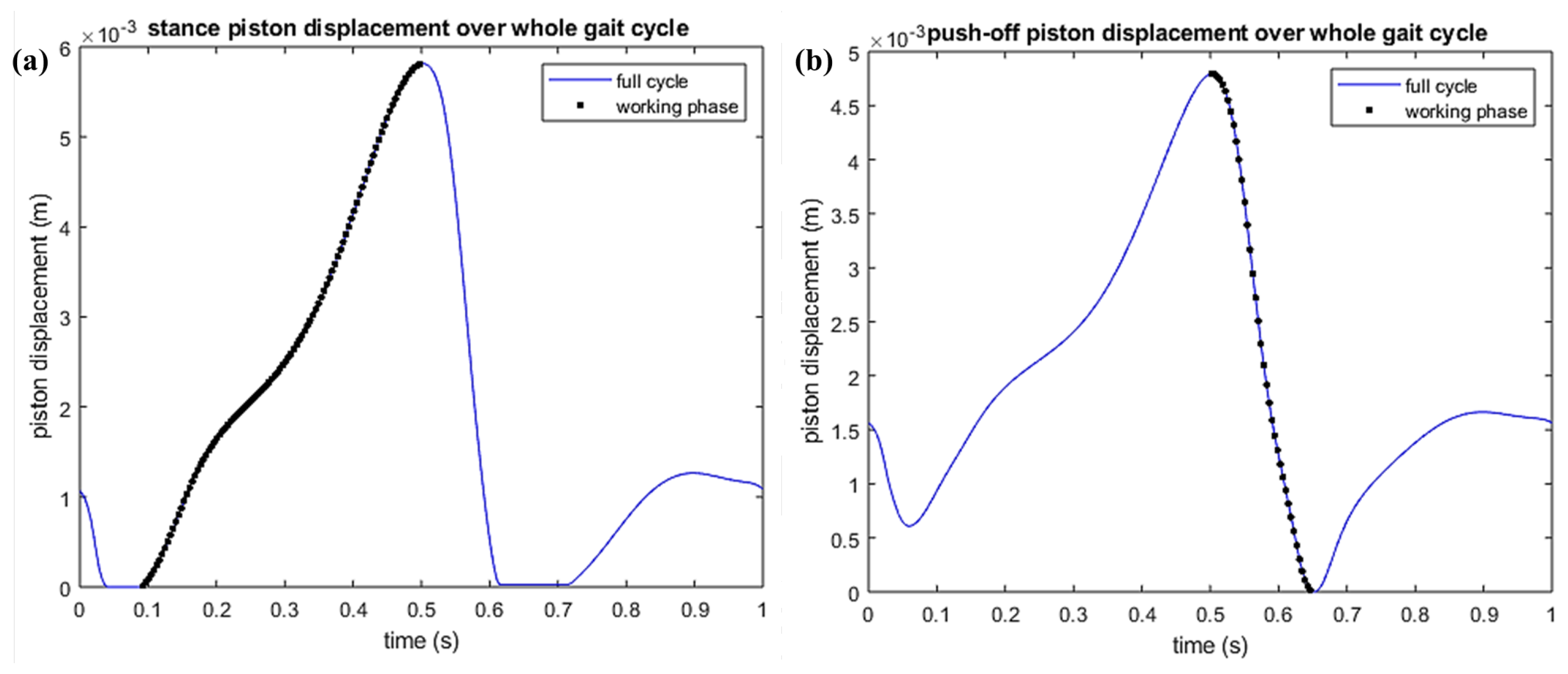
Figure 2.
Piston displacement (y) during the working phase (black dots) and over the complete gait cycle (blue solid line) for the stance cam-ram (a) and the push-off cam-ram (b). During the non-working phases, the working phase cam surface is followed within its range of cam angles; outside this range, the piston displacement is constant (flat sections of blue line).
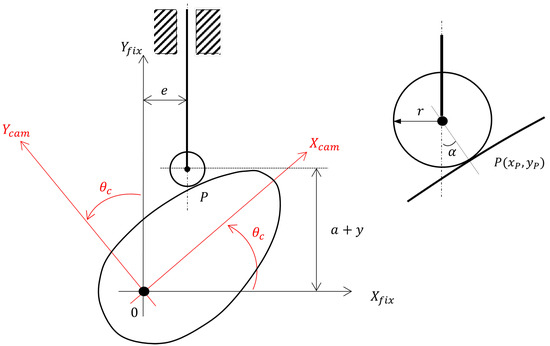
Figure 3.
Roller-follower on cam surface with the cam frame () rotated anticlockwise by an angle relative to the fixed frame (). Variable e defines the distance between the centre line of the follower and the centre line of the camshaft, while a describes the starting position of the follower in the vertical direction. On the right-hand side: a magnified view of the roller-follower shows the roller radius r, the cam pressure angle , and the contact point .
2.1.2. Updating Cam Profiles
The simulation model used to iteratively update the cam profiles simulates the operation of the whole system over one gait cycle, evaluating the changes in energy stored and released in the accumulator, and the total ankle torque in output from the device. Moreover, it includes all the friction terms and the torque generated by the non-working cam-ram that were previously neglected. Its only input is the ankle angle-versus-time profile obtained from experimental gait data, which is the only variable the user can govern once the new design is established.
For the first iteration, the initial cam profiles drive the simulation model. This allows for an accurate calculation of the actual camshaft torque , which is used to update over the working phases of the cams and, hence, the cam profiles, through a modified version of Equation (2) as follows:
In other words, for iteration is equal to the previous for iteration n plus an adjustment corresponding to adding the camshaft torque error (i.e., required minus actual camshaft torque). As the iterative algorithm converges, there are diminishing changes to the cam-ram dynamics, and the error approaches zero. in Equation (4) is the actual ram force including piston O-ring friction. For the second and subsequent iterations, the updated cam profile calculated using Equation (4) is used to drive the simulation model.
2.1.3. Sizing the Follower Return Springs
The outer loop of the design programme specifies the two linear return springs, which are part of the follower assembly and ensure cam–roller contact.
An iterative approach is also necessary in this case: knowledge of the normal forces acting between the cams and the rollers over the gait cycle is necessary to specify the follower return springs, but calculation itself depends on the follower return-spring parameters. In the first iteration, the return springs were omitted, and the simulation model was run to evaluate the normal cam forces without return springs () over the whole gait cycle. These data were used to calculate the minimum return-spring force () at every point in the gait cycle that would make greater than or equal to a minimum positive value (), which was chosen to guarantee cam operation under only compressive (positive) normal forces between cam and roller. In other words,
A search algorithm was implemented that found the ‘best’ return springs, i.e., those minimising the area included between the linear spring characteristic and the curve. This algorithm is explained in detail in [13]. As explained above, multiple iterations of this method should be used to converge on a solution, with the new values of replacing .
2.2. Classification of the Design Parameters
In order to conduct the preliminary design of the main components of the system, firstly, all the design parameters were classified into three categories: independent variables, dependent variables, and constants (see [13] for a complete description).
The independent variables can be further split into primary and secondary. The former are those that strongly influence the magnitude of the forces acting on the cam-ram components (i.e., cam, roller, follower, and bearings), which in turn determines the selection of these components, specifically their size, so that they can withstand those forces. Furthermore, by determining the forces in the system, these primary independent variables are also expected to directly affect the energy efficiency of the system. Conversely, secondary independent variables do not have a strong effect on the size of the cam-ram components. Nevertheless, they likely influence energy efficiency and the overall system dimensions.
To minimise the number of primary independent variables and thus simplify the design investigation, we initially identified three primary independent variables: gear ratio, maximum hydraulic pressure in the accumulator, and hydraulic ram bore. The gearbox, placed between the ankle and the camshaft, determines the camshaft torque; a change in its ratio directly affects the forces acting on the cam-ram components. Similarly, the maximum hydraulic pressure and the ram bore determine the hydraulic force acting on the piston and, in turn, the forces acting on the other cam-ram components.
We selected sensible values for these three variables (see Table 1) based on upper or lower limits that we thought provided reasonable constraints on the components’ sizes. A minimum gear ratio (GR) of one corresponds to a system without a gearbox and, consequently, zero gearbox losses and a simpler design, which would be a significant advantage. Two higher ratios were included in case a ratio of one leads to overly large forces and, hence, large cam-ram components. The ram bores (D) were chosen to (a) limit the size of the prosthesis by setting a maximum bore of 20 mm and (b) avoid the efficiency penalties associated with smaller hydraulic rams [15,16,17,18,19] by setting a minimum bore of 5 mm. Neubauer et al. [20] used a ram bore of approximately 13 mm in their hydraulic ankle–foot orthosis. They also used pressures around 100 bar demonstrating that this is practically feasible. Industrial hydraulic systems typically operate at pressures of up to 200 bar. Hence, for this application, 100 bar was set as the upper limit of the hydraulic pressure () with two smaller values of 20 bar and 50 bar. By combining these values for the three primary independent variables, 27 possible configurations are obtained for the two cam-ram systems.

Table 1.
Sensible values chosen for the three primary independent variables.
The secondary independent variables include two that were assumed to be important enough for optimum values to be investigated, namely the lowest position of the follower, a (Figure 3), and the follower offset, e (Figure 3).
Other secondary independent variables were assumed to be of lower importance and/or fairly arbitrary, but sensible values could be chosen based on practical constraints. These include the following:
- Diameter and length of the pipes between the rams and the accumulator, = 5 mm and = 50 mm. These are realistic values, and the associated flow losses were assumed to have a negligible effect on the working phase performances of the cam-rams, during which power flows are large. This assumption was confirmed through a sensitivity study explained in [13].
- An accumulator volume of = 250 cc was chosen, which was considered small enough to be integrated within the prosthesis pylon, as envisaged, and large enough to store energy over many gait cycles [11,13].
Finally, some design constraints were defined to guide the preliminary design investigation:
- To limit the overall size of the cam-rams, the total length of the hydraulic rams, when the piston is at the end of its outstroke, should be no more than 150 mm. Given that a cylinder for pressures up to 100 bar has an instroke length of approximately 100 mm, based on hydraulic cylinder catalogues (HYDAIRA [21] for instance), the maximum stroke was set to = 50 mm.
- To limit the overall size of the cam-rams, the upper limit for both the offset e and the distance a was set to = 50 mm.
- Considering the above bounds, a maximum roller diameter of = 30 mm was set.
- The maximum cam pressure angle was set to ° because cam design handbooks generally suggest limiting the pressure angle to 30° to avoid high lateral forces and, hence, high follower friction. The same 30° limit was also used by Realmuto et al. [22] in the design of their powered ankle prosthesis.
2.3. Preliminary Design Investigation
A preliminary design investigation was conducted to establish a set of “close to optimal” design parameters, which were then used to simulate the potential performance of the novel design; the results are reported in [11,13]. The following subsections describe the four main stages of this preliminary design investigation.
2.3.1. Determine a Subset of Feasible Designs (Primary Independent Variables)
The first stage of the preliminary design investigation reduced the number of feasible designs (i.e., combinations of primary independent variables) by eliminating designs that are unrealistic in terms of size.
We started by considering a gear ratio of GR = 1, i.e., a system without a gearbox. This reduced the number of combinations to be analysed from 27 to 9. For each of the nine combinations used for both cam-ram systems (eighteen cases), the length of the piston stroke was estimated to exclude those combinations with a stroke greater than = 50 mm. Neglecting all losses, the stroke lengths were estimated by considering the negative and the positive ankle work performed during the working phases of the stance and the push-off systems, respectively, and, hence, the corresponding energy to be stored in and released from the accumulator. The total work performed by the hydraulic rams over their working phases is . Rearranging for piston stroke and assuming a constant accumulator pressure, this gives:
The energy stored during the working phase of the stance system amounts to approximately 18.9 J, while the energy released during the working phase of the push-off system amounts to approximately 11.9 J, obtained by numerical integration of the ankle power (data collected by Bari for healthy level walking at a self-selected speed [14]).
2.3.2. Determine the Roller Diameters
The second stage of the preliminary design investigation was to find roller diameters (a dependent variable) that can withstand the cam–roller contact forces. For each feasible design deriving from the previous design stage, the MATLAB simulation model was used to evaluate the maximum value of the normal force () acting between the cam and the roller for each of the two working phases, generated by the maximum hydraulic force acting on each ram (). Then, the minimum roller diameter () able to bear the maximum force was identified considering the quoted maximum dynamic radial loads from catalogues: SKF [23] for rollers with a diameter bigger than 16 mm; IKO [24,25] for rollers with a diameter smaller than 16 mm.
Note that to run the MATLAB simulation model for the first time, the roller diameter was initially set to 26 mm, with this being the largest available in [23] that satisfied the design constraint mm. Also, arbitrary initial values for distance a (40 mm) and offset e (15 mm) were used.
The simulation model was then rerun with the identified smaller roller diameter to verify that the resulting maximum normal force did not require further modification of the roller selection. Conversely, if the minimum roller diameter had exceeded the maximum available value (26 mm) that satisfies the constraint mm, then this case (i.e., one design used in one working phase) would have been excluded from the next stage of the design process.
2.3.3. Determine the Two Secondary Independent Variables, a and e
In the third stage of the preliminary design investigation, the feasible designs identified in the previous subsections (satisfying mm and mm) were further analysed to find good values for the two secondary independent variables, distance a and offset e, which affect the working phase performance of the two cam-rams. Specifically, altering a and e changes the geometry shown in Figure 3 and, hence, the cam pressure angle .
Given the previously defined design constraints, the aim was to find values of a and e which satisfy and keep the cam pressure angle below 30° during the two cam-ram systems’ working phases, while also minimising a and e as far as possible. All simulations in this third stage used the correct roller diameter from the previous step.
The process implemented in MATLAB to identify good values for a and e followed the steps below:
- The distance a was initially set to its upper limit ( = 50 mm to minimise cam pressure angle , and hence follower friction, because increasing a reduces [13].
- A search was undertaken over the range mm to find the optimum value of e minimising cam pressure angle . Specifically, for each value of e, the MATLAB simulation model was run to find the largest absolute value of cam pressure angle, , during the working phase of the cam-ram (the objective function to be minimised).
- Depending on the optimum (minimum) value of , there were three options:
- (a)
- If , that combination of primary independent variables was eliminated.
- (b)
- If , that combination was considered acceptable with the current value of a and the optimum value of e.
- (c)
- If , smaller values of the distance a were tried to reduce the size of the cam-ram system. For each new value of a, step 2 was repeated.
2.3.4. Compare Energy Losses
In the fourth and last stage of the preliminary design investigation, for each cam-ram system, the design alternatives deriving from the previous design stage were compared in terms of their energy losses. Power flows were calculated, and then the energy balance over the cam-ram’s working phase was obtained by integration (see [13] for details). For each design alternative, four energy terms were considered:
- The energy input: from the ankle for the stance system; from the accumulator for the push-off system.
- The energy output: the energy stored in the accumulator for the stance system, and the energy output to the ankle for the push-off system.
- The energy lost because of friction between cam and roller, in the roller, at the follower guide, and at the cylinder O-ring (gearbox friction is zero because there is no gearbox).
- The energy stored in the mechanical components of the system, including strain energy in the parallel torsional spring, and the kinetic and potential energies of the roller and follower.
It should be noted that an early-stage simulation model was used for the preliminary design investigation, which only modelled the friction losses directly associated with the two cam-rams during their working phases. Therefore, losses in the two cam-ram systems during their non-working phases, pipe flow losses, losses in the accumulator because of heat transfer, and the two follower return springs were neglected. However, it was assumed these would have little effect on the selection of cam-ram design parameters.
3. Results
The simulation-based design programme, by simulating the operation of the whole system over one gait cycle, successfully generated cam profiles outputting an ankle torque that closely matches that of an intact ankle, while allowing energy storage and release in the accumulator. Five iterations of the simulation model were used because the residuals (i.e., ) for the two working phases decreased as the number of iterations increased from one to five, after which they increased slightly up to the eighth iteration and then remained constant. The maximum difference between the required and the actual torque was just under 0.02 Nm in the working phases.
When it came to the size of the follower return springs, it was found that multiple iterations of the search algorithm were unnecessary to converge on a solution. When the spring parameters from the first iteration were included in the simulation model to re-evaluate the normal cam forces, was indeed greater than over the whole gait cycle, and the smallest value of was just less than 22 N. This was deemed to be sufficiently accurate as the chosen = 20 N was to some extent arbitrary.
Then, by replacing the values of energy stored and released in Equation (6), together with the maximum hydraulic pressure and the ram bore from Table 1, the results shown in Table 2 were obtained. The five bold values correspond to those combinations of primary independent variables with a stroke smaller than , which were therefore carried forward to the next stage of the design process. Interestingly, the same five combinations of the primary independent variables (feasible designs) were carried forward for both cam-ram systems.
Table 2.
Nominal stroke length (mm) for the stance piston and the push-off piston (considering a system without a gearbox). Bold values correspond to stroke lengths smaller than the upper limit = 50 mm.
The roller selection procedure was repeated for each of the five feasible designs for both cam-ram systems (10 cases, as shown in Table 2), and it did not reduce the number of feasible designs (i.e., no minimum roller diameters exceeded the maximum available value of 26 mm, satisfying the constraint mm). The minimum roller diameter was 19 mm for one feasible design ( = 100 bar and D = 20 mm) and 16 mm for the other four feasible designs. This result applied to both cam-ram systems.
As a result of the third stage of the design process, in which good values for the two secondary independent variables (distance a and offset e) were determined, the number of feasible designs (combinations of primary independent variables) was reduced from five to two as shown in Table 3. For the first of these, three alternative values of the distance a were carried forward to the next stage of the design process. This result applied to both cam-ram systems.
Table 3.
Design alternatives remaining after evaluating the roller diameters and the two secondary independent variables a and e for the subset of feasible designs. The design parameters are the same for both cam-ram systems except for the offset e of the 4th design alternative.
Results of the energy analysis conducted in the last stage of the design process showed that, for both cam-ram systems, the third design alternative in Table 3 has the smallest energy losses and also the smallest value of distance a (30 mm), which helps to minimise the size of the cam-ram system. Hence, the recommended design parameters for both cam-ram systems are those shown for the third design alternative in Table 3. The associated energy losses for the stance and the push-off cam-ram systems are shown in Table 4.
Table 4.
Energy balance for the two cam-ram systems over their working phases for the third combination of Table 3 ( bar; mm; mm; and mm).
4. Discussion
The simulation-based design programme described in this paper successfully enables the specification of the cam profiles and the follower return springs in the energy storage and return prosthetic ankle presented in [11].
Five iterations are enough for the design programme to determine cam profiles able to generate a prosthetic ankle torque matching that of a healthy subject over the two cam-ram working phases (with an error less than 0.02 Nm). One iteration is enough for the design programme to size return springs that guarantee satisfactory cam–roller contact. The design programme also calculates the magnitude of the forces acting within the two cam-ram systems, which are used to determine the sizes of the main components so that they can withstand those forces.
The design programme is used to conduct a preliminary design investigation to specify the key components of the prosthesis affecting its size and energy efficiency. Results of this preliminary investigation show that, with no gearbox, the best designs for the two cam-ram systems are the same, including the following: a maximum hydraulic pressure of 100 bar; a ram bore of 20 mm; a roller diameter of 19 mm (a value also used by Realmuto et al. [22] for the cam–roller-follower system in their ankle prosthesis); an offset e of 19 mm; and a distance a of 30 mm. This design minimizes the energy losses while keeping the system dimensions within acceptable limits.
The energy balance results for this design alternative, during the working phases of the two cam-ram systems, are very promising [11]. Specifically, the energy losses do not exceed of the energy input to the system (i.e., from the ankle for the stance system and from the accumulator for the push-off system).
However, the two cam-ram systems were designed to have good performances only in their working phases. As previously mentioned, only the friction losses directly associated with the two cam-rams during their working phases were considered in the early-stage simulation model used for this preliminary design investigation. Therefore, to assess the performance of the final design, all of the previously neglected sources of energy loss were included in the model: losses in the non-working phases in the two cam-ram systems associated with rolling resistance between rollers and cams, bearings, and piston O-rings; flow losses in pipes and discrete components (e.g., inlets, exits, bends, and valves); losses in the accumulator because of heat transfer. When all significant sources of energy dissipation are included, there is an increase in the energy losses of about of the total external energy input at the ankle over the gait cycle (i.e., ) [11], which can be reduced to with small changes to the design, as explained in detail in [11,13]. Nevertheless, even then, the cam-ram performances in their working phases will likely dominate the design decisions, as assumed in this study, given that the power flows are much greater in the working phases.
The simulation results suggest the proposed prosthesis would store and release gait energy more efficiently through the use of hydraulics and an accumulator, leading to a reduction in metabolic energy consumption during walking without the need for external power sources. Furthermore, our semi-active design needs only small batteries for control, not for propulsion, potentially reducing weight and increasing autonomy (range between charges). Conversely, while representing a significant advancement over passive designs by providing active push-off propulsion, existing fully active prosthetic feet, such as the Ottobock Empower (the only one on the market), rely heavily on battery power, which increases weight, limits autonomy, and increases maintenance requirements. As stated in [11], future work includes physical prototyping and experimental validation with prosthetic users. This is necessary to assess user satisfaction and evaluate individual ankle response through gait analysis. In vivo testing results will either confirm simulation predictions or lead to a further simulation-based optimisation of the cam profiles and other key components for different walking conditions.
Overall, a simulation-based design process represents a cost-effective and sustainable alternative to heuristic approaches in prosthetic design. It enables a comprehensive evaluation of all device components and their role within the system dynamics, supported by a rigorous mathematical model. Integrating simulations of the device’s operation into an iterative design process represents an efficient approach to advancing prosthetic technology development.
As well as documenting the design of a particular novel prosthetic ankle, the authors believe this is a useful exemplar of how a complex design problem can be broken down into a series of sub-problems, supported by simulation-based design programs. This includes the classification of design parameters for prioritisation purposes, using iterative simulation to converge on solutions, and following a priority-based sequence of design steps.
Author Contributions
Conceptualisation, A.P., J.G. and D.H.; methodology, A.P., J.G. and D.H.; software, A.P., J.G. and D.H.; validation, A.P., J.G. and D.H.; writing-original draft preparation, A.P., J.G. and D.H.; writing-review and editing, A.P. and D.H.; visualisation, A.P. and D.H.; supervision, D.H. All authors have read and agreed to the published version of the manuscript.
Funding
This work was supported by the University of Salford as part of the Graduate Teaching Studentship Scheme.
Institutional Review Board Statement
Not applicable.
Informed Consent Statement
Not applicable.
Data Availability Statement
The original contributions presented in this study are included in the article. Further inquiries can be directed to the corresponding author.
Conflicts of Interest
The authors declare no conflicts of interest. The funders had no role in the design of the study; in the collection, analyses, or interpretation of data; in the writing of the manuscript; or in the decision to publish the results.
Abbreviations
The following abbreviations are used in this manuscript:
| ESR | Energy storage and return |
| GR | Gear ratio |
Appendix A
Table A1.
Nomenclature used in this paper.
Table A1.
Nomenclature used in this paper.
| a | arbitrary constant defining the starting position of the follower in the vertical (y-axis) direction (m) | P | operating pressure (Pa) |
| A | ram bore area (oil side) (m2) | accumulator pressure (Pa) | |
| D | ram bore (m) | atmospheric pressure (Pa) | |
| pipe diameter (m) | cylinder pressure (Pa) | ||
| roller diameter (m) | max accumulator hydraulic pressure (Pa) | ||
| e | offset given by the distance between the centre line of the follower and the centre line of the camshaft (m) | r | roller radius (m) |
| hydraulic ram force (N) | stroke | piston stroke (m) | |
| normal force acting between the cam and the roller (N) | actual torque at the camshaft (Nm) | ||
| minimum desired value for the normal force between cam and roller (N) | required torque at the camshaft (Nm) | ||
| normal force between cam and roller when the two return springs are not included in the system (N) | stance cam torque (Nm) | ||
| return-spring force (N) | accumulator volume (m3) | ||
| required return-spring force (N) | y | piston linear displacement (m) | |
| W | hydraulic ram work/cam work (J) | k | return-spring constant (N/m) |
| cam pressure angle (rad) | pipe length (m) | ||
| cam angle of rotation (rad) | contact point (with coordinates) between cam and roller (m) |
References
- Versluys, R.; Beyl, P.; Van Damme, M.; Desomer, A.; Van Ham, R.; Lefeber, D. Prosthetic feet: State-of-the-art review and the importance of mimicking human ankle-foot biomechanics. Disabil. Rehabil. Assist. Technol. 2009, 4, 65–75. [Google Scholar] [CrossRef]
- Perry, J.; Burnfield, J.M.; Newsam, C.J.; Conley, P. Energy expenditure and gait characteristics of a bilateral amputee walking with C-leg prostheses compared with stubby and conventional articulating prostheses. Arch. Phys. Med. Rehabil. 2004, 85, 1711–1717. [Google Scholar] [CrossRef] [PubMed]
- Cherelle, P.; Mathijssen, G.; Wang, Q.; Vanderborght, B.; Lefeber, D. Advances in Propulsive Bionic Feet and Their Actuation Principles. Adv. Mech. Eng. 2014, 6, 984046. [Google Scholar] [CrossRef]
- Segal, A.D.; Zelik, K.E.; Klute, G.K.; Morgenroth, D.C.; Hahn, M.E.; Orendurff, M.S.; Adamczyk, P.G.; Collins, S.H.; Kuo, A.D.; Czerniecki, J.M. The effects of a controlled energy storage and return prototype prosthetic foot on transtibial amputee ambulation. Hum. Mov. Sci. 2012, 31, 918–931. [Google Scholar] [CrossRef]
- Adamczyk, P.G.; Kuo, A.D. Mechanisms of Gait Asymmetry Due to Push-Off Deficiency in Unilateral Amputees. IEEE Trans. Neural Syst. Rehabil. Eng. 2015, 23, 776–785. [Google Scholar] [CrossRef] [PubMed]
- Huang, T.P.; Shorter, K.A.; Adamczyk, P.G.; Kuo, A.D. Mechanical and energetic consequences of reduced ankle plantar-flexion in human walking. J. Exp. Biol. 2015, 218, 3541–3550. [Google Scholar] [CrossRef] [PubMed]
- van Schaik, L.; Geertzen, J.H.B.; Dijkstra, P.U.; Dekker, R. Metabolic costs of activities of daily living in persons with a lower limb amputation: A systematic review and meta-analysis. PLoS ONE 2019, 14, e0213256. [Google Scholar] [CrossRef] [PubMed]
- Herr, H.; Grabowski, A.M. Bionic ankle–foot prosthesis normalizes walking gait for persons with leg amputation. Proceeding R. Soc. B 2012, 279, 457–464. [Google Scholar] [CrossRef]
- Laschowski, B.; McPhee, J.; Andrysek, J. Lower-Limb Prostheses and Exoskeletons With Energy Regeneration: Mechatronic Design and Optimization Review. J. Mech. Robot. 2019, 11, 040801. [Google Scholar] [CrossRef]
- Cimolato, A.; Driessen, J.J.M.; Mattos, L.S.; De Momi, E.; Laffranchi, M.; De Michieli, L. EMG-driven control in lower limb prostheses: A topic-based systematic review. J. Neuroeng. Rehabil. 2022, 19, 43. [Google Scholar] [CrossRef] [PubMed]
- Pace, A.; Gardiner, J.; Kenney, L.; Howard, D. Simulated Performance of an Energy Storage and Return Prosthetic Ankle Based on Cams and Miniature Hydraulics. IEEE Trans. Med. Robot. Bionics 2022, 4, 230–240. [Google Scholar] [CrossRef]
- Ziegler-Graham, K.; MacKenzie, E.J.; Ephraim, P.L.; Travison, T.G.; Brookmeyer, R. Estimating the Prevalence of Limb Loss in the United States: 2005 to 2050. Arch. Phys. Med. Rehabil. 2008, 89, 422–429. [Google Scholar] [CrossRef] [PubMed]
- Pace, A. A Novel Hydraulic Energy-Storage-And-Return Prosthetic Ankle: Design, Modelling and Simulation. Ph.D. Dissertation, University of Salford, Salford, UK, 2020. [Google Scholar]
- Bari, A.Z. An Efficient Energy Storage and Return Prosthesis. Ph.D. Dissertation, University of Salford, Salford, UK, 2013. [Google Scholar]
- Durfee, K.; Xia, J.; Hsiao-Wecksler, E. Tiny Hydraulics for Powered Orthotics. In Proceedings of the IEEE International Conference on Rehabilitation Robotics (ICORR), Rehab Week Zurich, ETH Zurich Science City, Zurich, Switzerland, 29 June–1 July 2011; Volume 279, pp. 903–908. [Google Scholar]
- Xia, J.; Braun, K.L.; Durfee, W.K. Small-Scale Hydraulics for Human Assist Devices. In Proceedings of the Design of Medical Devices Conference (DMD), Minneapolis, MN, USA, 12–14 April 2011. [Google Scholar]
- Xia, J.; Durfee, W.K. Modeling of Tiny Hydraulic Cylinders. In Proceedings of the 52nd National Conference on Fluid Power, Las Vegas, NV, USA, 23–25 March 2011; pp. 657–662. [Google Scholar]
- Xia, J.; Durfee, W.K. Analysis of Small-Scale Hydraulic Actuation Systems; University of Minnesota: Minneapolis, MN, USA, 2011. [Google Scholar]
- Xia, J.; Durfee, W.K. Experimentally validated models of o-ring seals for tiny hydraulic cylinders. In Proceedings of the Symposium on Fluid Power & Motion Control (FPMC), ASME, Bath, UK, 10–12 September 2014. [Google Scholar]
- Neubauer, B.C.; Nath, J.; Durfee, W.K. Design of a Portable Hydraulic Ankle-Foot Orthosis. In Proceedings of the 36th Annual International Conference of the IEEE Engineering in Medicine and Biology Society (EMBC), Chicago, IL, USA, 26–30 August 2014. [Google Scholar] [CrossRef]
- HYDAIRA. Hydraulic Cylinders. Available online: http://www.hydaira.ch/produkte/zu.php?nav=prod&lang=en (accessed on 15 November 2024).
- Realmuto, J.; Klute, G.; Devasia, S. Nonlinear Passive Cam-Based Springs for Powered Ankle Prostheses. J. Med. Devices 2015, 9, 011007. [Google Scholar] [CrossRef]
- SKF. Rolling Bearings; SKF: Gothenburg, Sweden, 2013. [Google Scholar]
- IKO. Cam Followers & Roller Followers; IKO, NIPPON THOMPSON CO., LTD.: Tokyo, Japan, 2016. [Google Scholar]
- IKO. Cam Followers; IKO, NIPPON THOMPSON CO., LTD.: Tokyo, Japan, 2017. [Google Scholar]

Disclaimer/Publisher’s Note: The statements, opinions and data contained in all publications are solely those of the individual author(s) and contributor(s) and not of MDPI and/or the editor(s). MDPI and/or the editor(s) disclaim responsibility for any injury to people or property resulting from any ideas, methods, instructions or products referred to in the content. |
© 2025 by the authors. Licensee MDPI, Basel, Switzerland. This article is an open access article distributed under the terms and conditions of the Creative Commons Attribution (CC BY) license (https://creativecommons.org/licenses/by/4.0/).