Study on the Impact Mitigation Effect of Artificial Rock Backfill Layers for Submarine Pipelines Based on Physical Model Tests and Numerical Simulations
Abstract
:1. Introduction
2. Materials and Methods
2.1. Theoretical Basis and Scale Relationships of Physical Model Experimentation
2.1.1. Anchor’s Falling Velocity in Air
2.1.2. Anchor’s Maximum Terminal Falling Velocity vmax in Water
2.1.3. Anchor’s Kinetic Energy When Impacting the Pipeline or Protective Layer
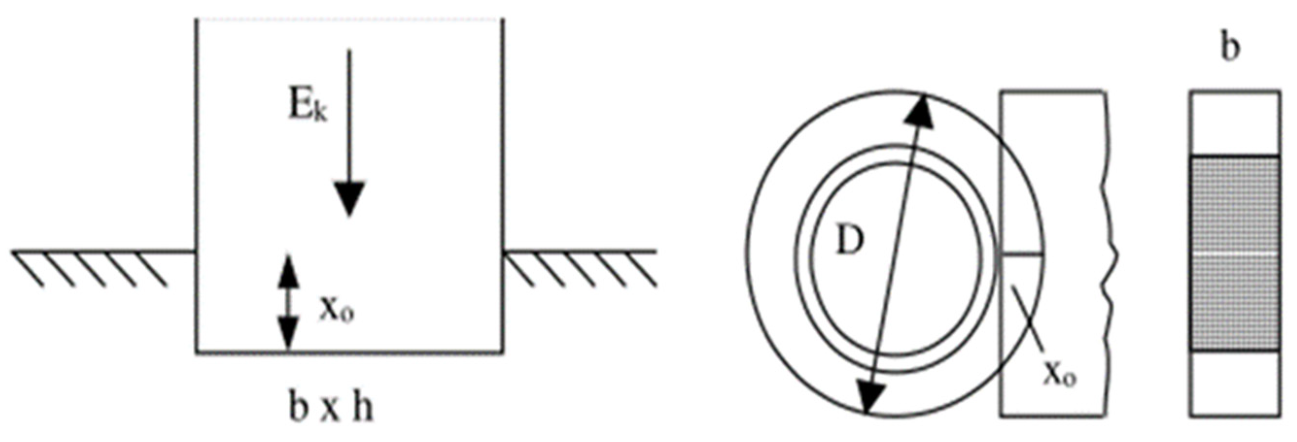
2.1.4. Kinetic Energy That Concrete Coating Can Resist from the Impact
2.1.5. Scale Relationships of Physical Model Experiments
2.2. Establishment of Physical Model Experiments
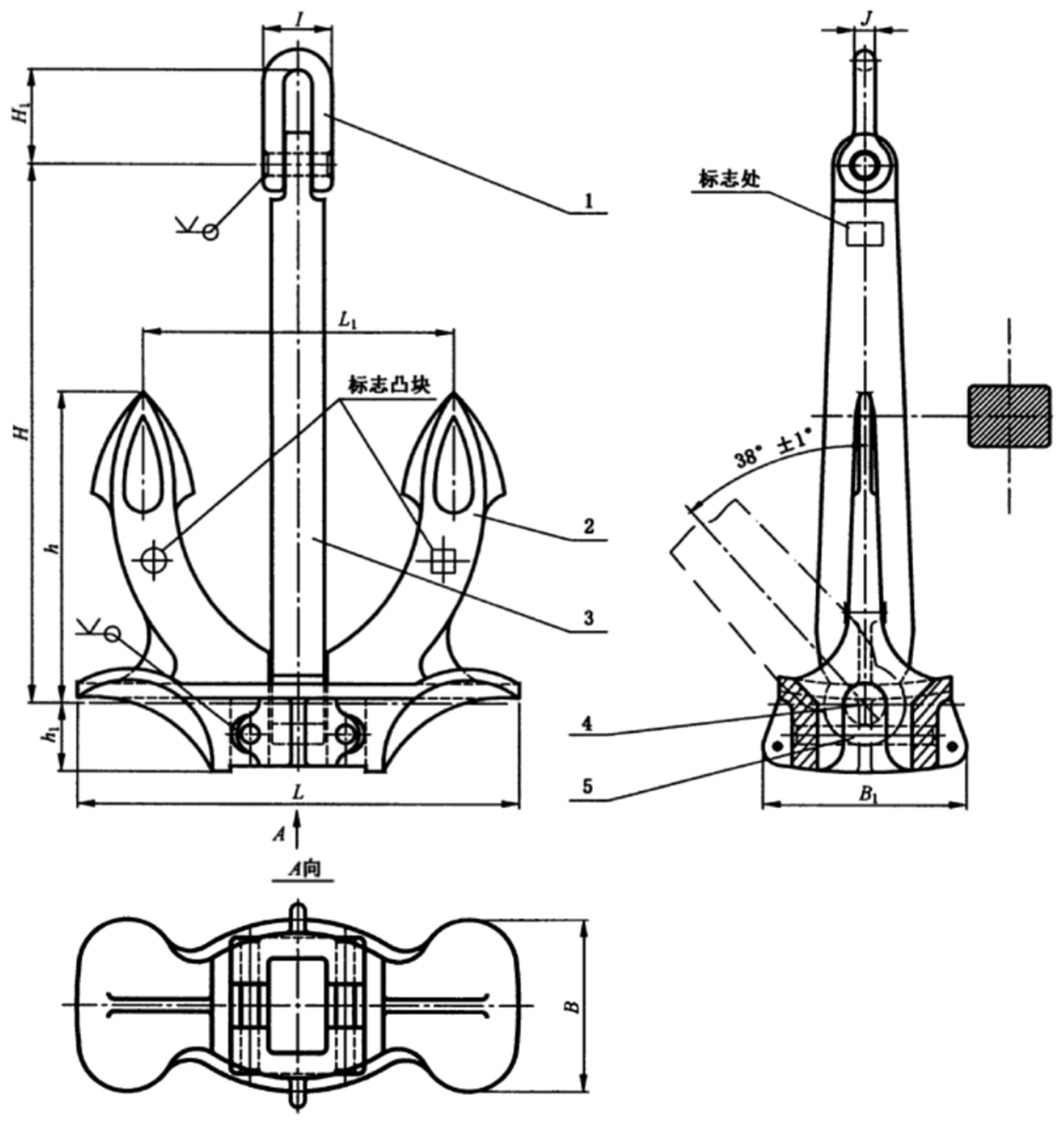
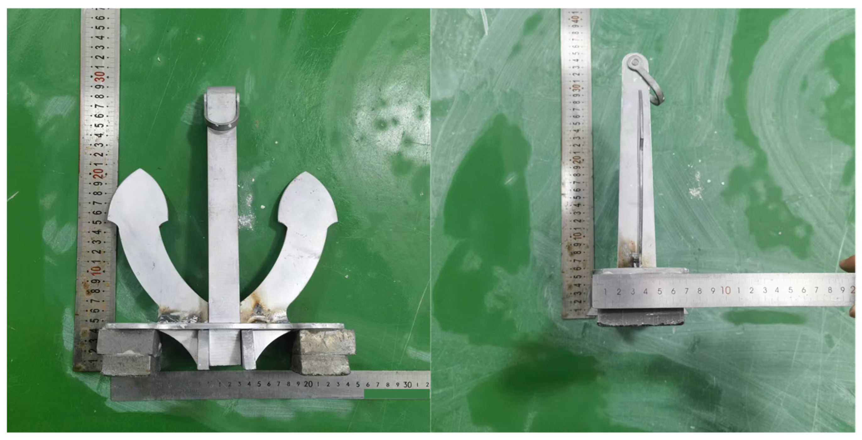
2.2.1. Anchor Selection and Model Anchor Preparation
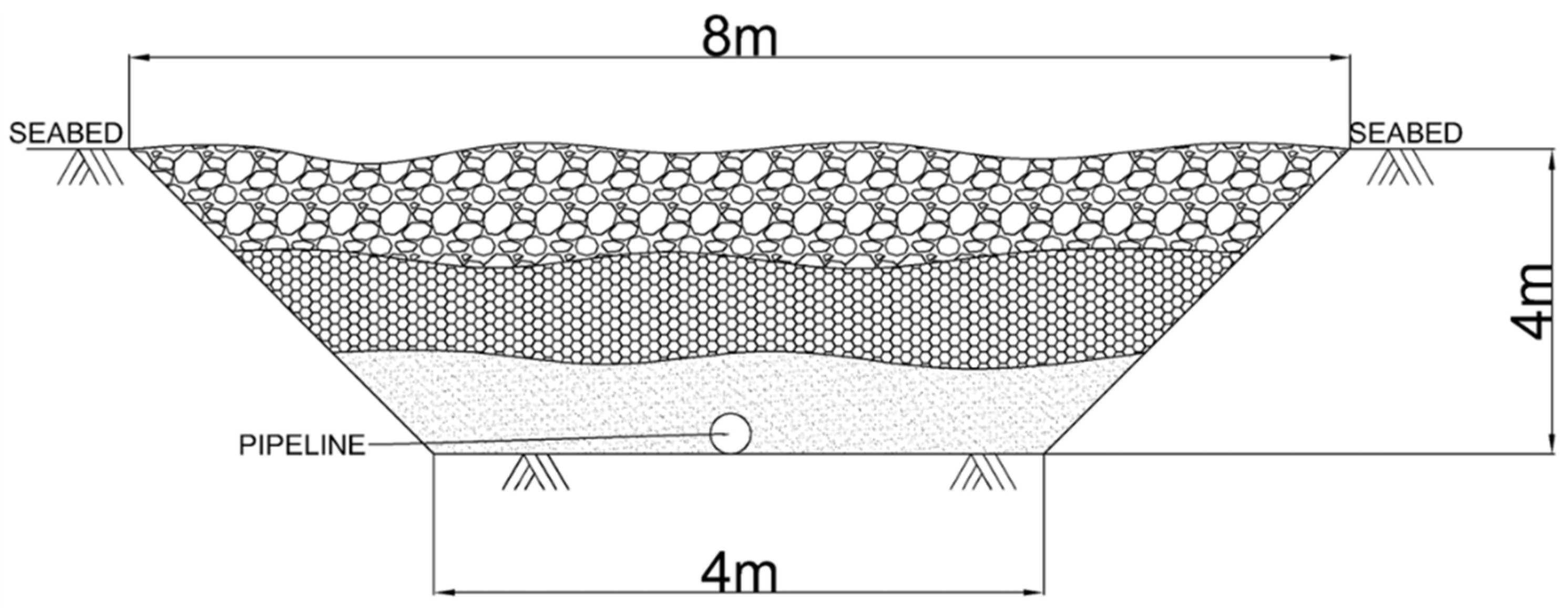
2.2.2. Pipeline Trench Shape
2.2.3. Gradation of Rock Protection Layer Particle Size and Trench Model Soil Sample
2.3. Physical Model Test Plan
2.3.1. Impact Energy Ek That the Concrete Coating Can Resist
2.3.2. Maximum Impact Energy EE That the Anchor Can Reach in Water
2.3.3. Anchor Drop Height H
2.4. Experimental Setup and Procedure
2.5. Numerical Model Construction
3. Results and Discussion
3.1. Physical Model Test Conditions Setup
3.2. Numerical Simulation Conditions Setup
3.3. Physical Model Test Results and Analysis
3.3.1. Total Force Sensor Results
3.3.2. Thin-Film Sensor Results
3.3.3. Summary and Analysis of Condition Safety Factors
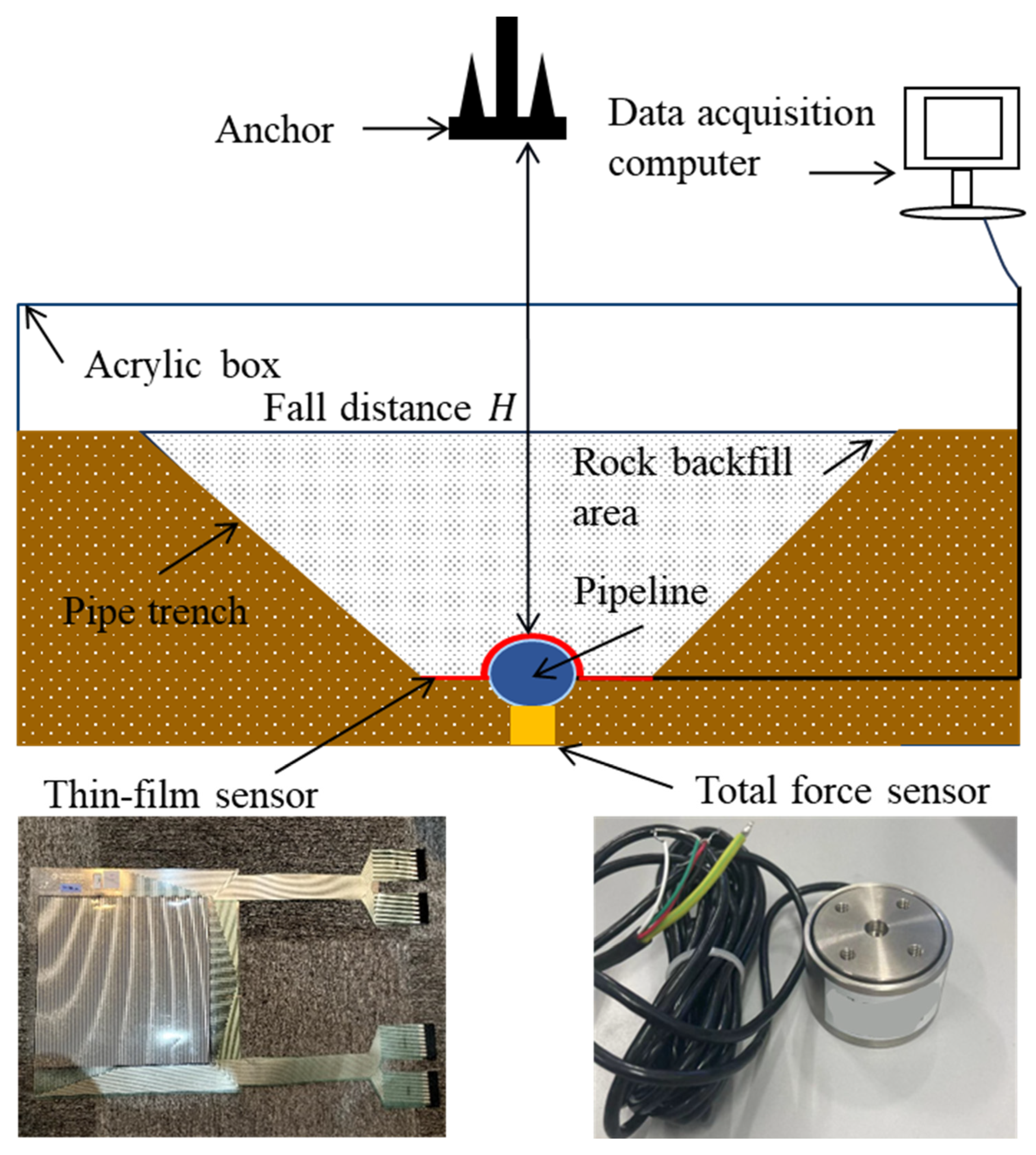
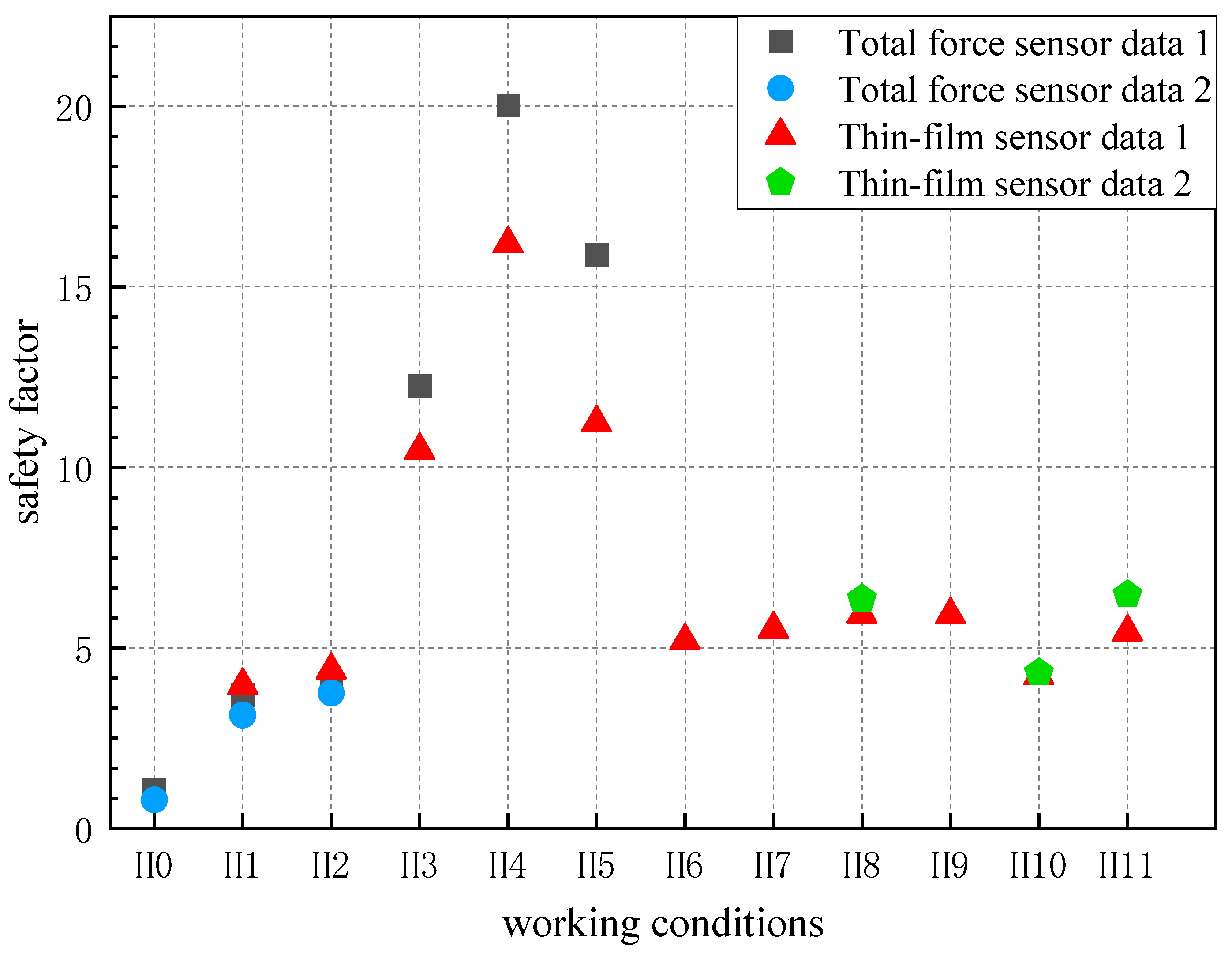
- Influence of artificial backfill layer rock particle size: When the backfill layer thickness is 13 cm (Conditions H1, H2), adding small particle size rock to the protective layer increases the safety factor by 44%. When the backfill layer thickness increases to 26 cm (Conditions H3, H4, H5), the safety factor increases by 16% with the addition of small particle size rock. In cases with soft mud bedding layer (Conditions H6, H7), the increase in safety factor due to adding small particle size rock is not significant, at only 6%. In the case with sandy soil bedding layer (Conditions H8, H9), the protective effect of adding small particle size rock remains largely unchanged. In the case of underlying high-strength clay layers (Conditions H10, H11), adding small particle size rock increases the safety factor by 39.1%. When fully backfilled with 26 cm of medium particle size rock, compared with fully backfilled with large particles (Conditions H3, H4), the safety factor increases by 58%.
- Influence of artificial backfill layer thickness: When the artificial backfill layer thickness increases from 0 to 13 cm with large particle size rock (Conditions H0, H1), the safety factor increases by 257%. When the thickness is further increased from 13 cm to 26 cm with large particle size backfill, the safety factor increases by 216%. The increase in safety factor shows a linear relationship with the increase in backfill layer thickness.
- Influence of trench bedding layer type: Among the three different bedding layers (Conditions H6, H8, H10), the safety factor of the soft mud bedding layer is 21% higher than that of the high-strength clay bedding layer, while the safety factor of the sandy soil bedding layer is 18% higher than that of the soft mud bedding layer.
3.4. Numerical Simulation Results and Analysis
3.4.1. Validation of the Angle of Repose for Rock Pile
3.4.2. Numerical Simulation Conditions Results and Analysis
4. Conclusions
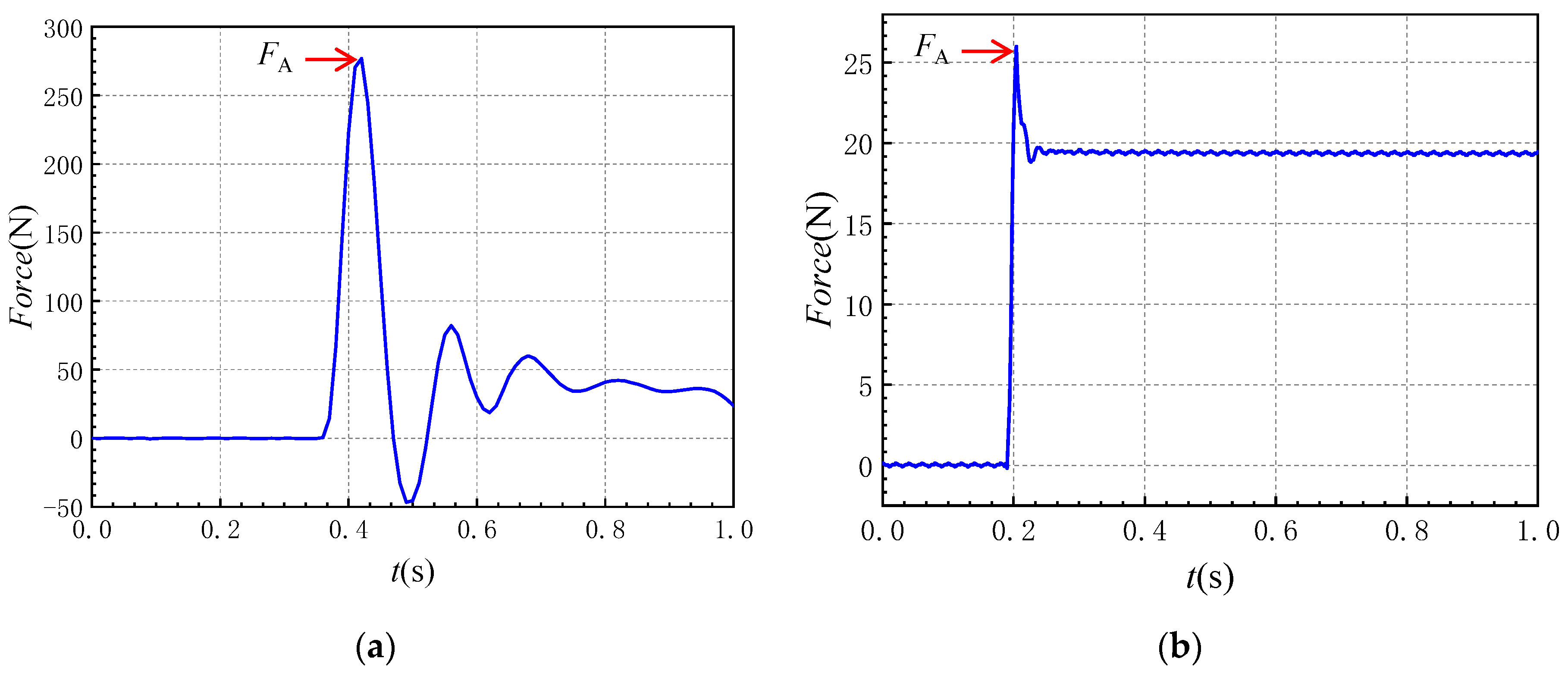
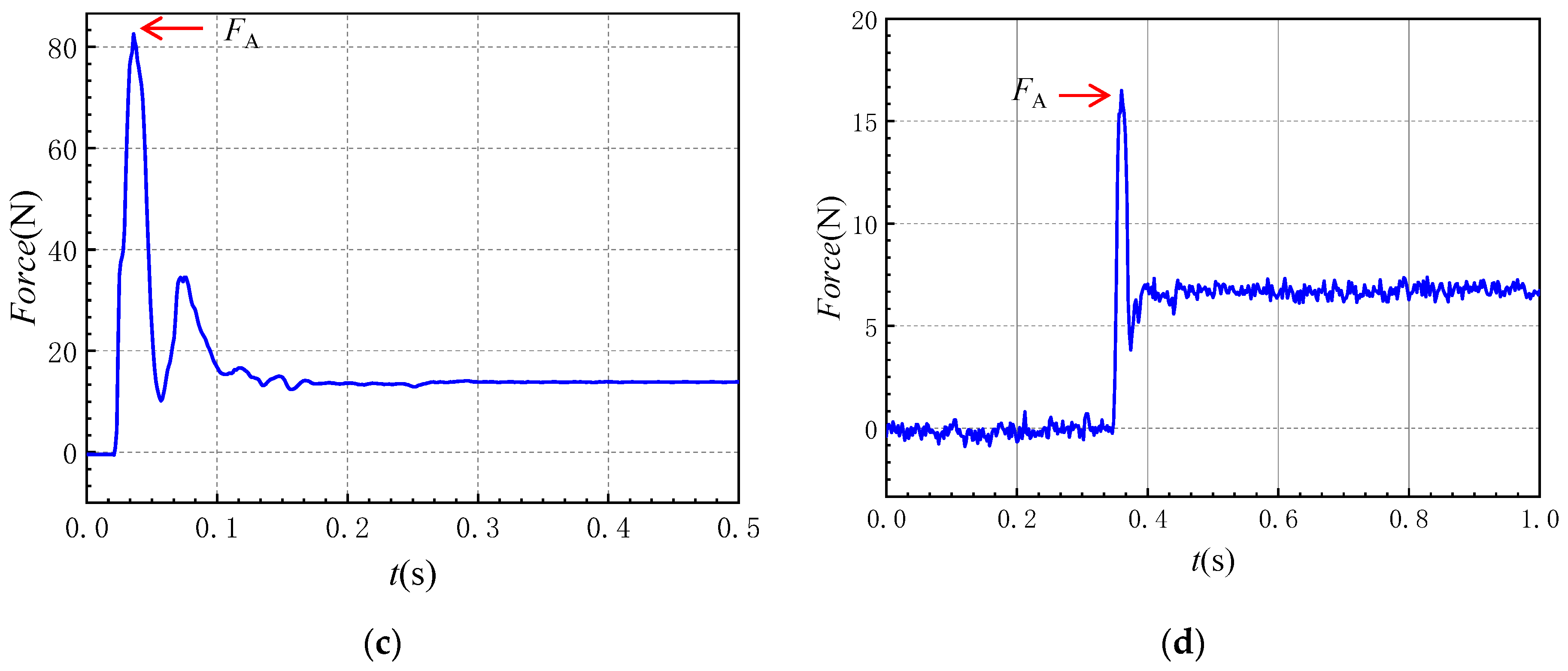
- The experimental results are presented in the form of force–time curves measured by force sensors. The results show that, as the backfill layer thickness increases, the safety factor improvement brought by adding small-particle backfill decreases. When the bedding layer is high-strength clay, the addition of small-particle backfill significantly improves the safety factor, while the effect is smaller with soft mud and sand cushion layers. The buffering effect of medium-sized particle backfill is significantly better than that of large-particle backfill. The thickness of the backfill layer significantly improves the buffering effect in a linear manner. The buffering effect of sand bedding layers is better than that of soft mud bedding layers, while high-strength clay bedding layers perform the worst.
- The advantage of the FEM-DEM numerical method lies in its ability to effectively simulate the discrete characteristics of the artificial backfill layer’s rock material using the discrete element method (DEM). Additionally, when coupled with the finite element method (FEM), it accurately models the dynamic responses between the artificial backfill layer, pipeline, seabed soil, and the anchor during the impact event.
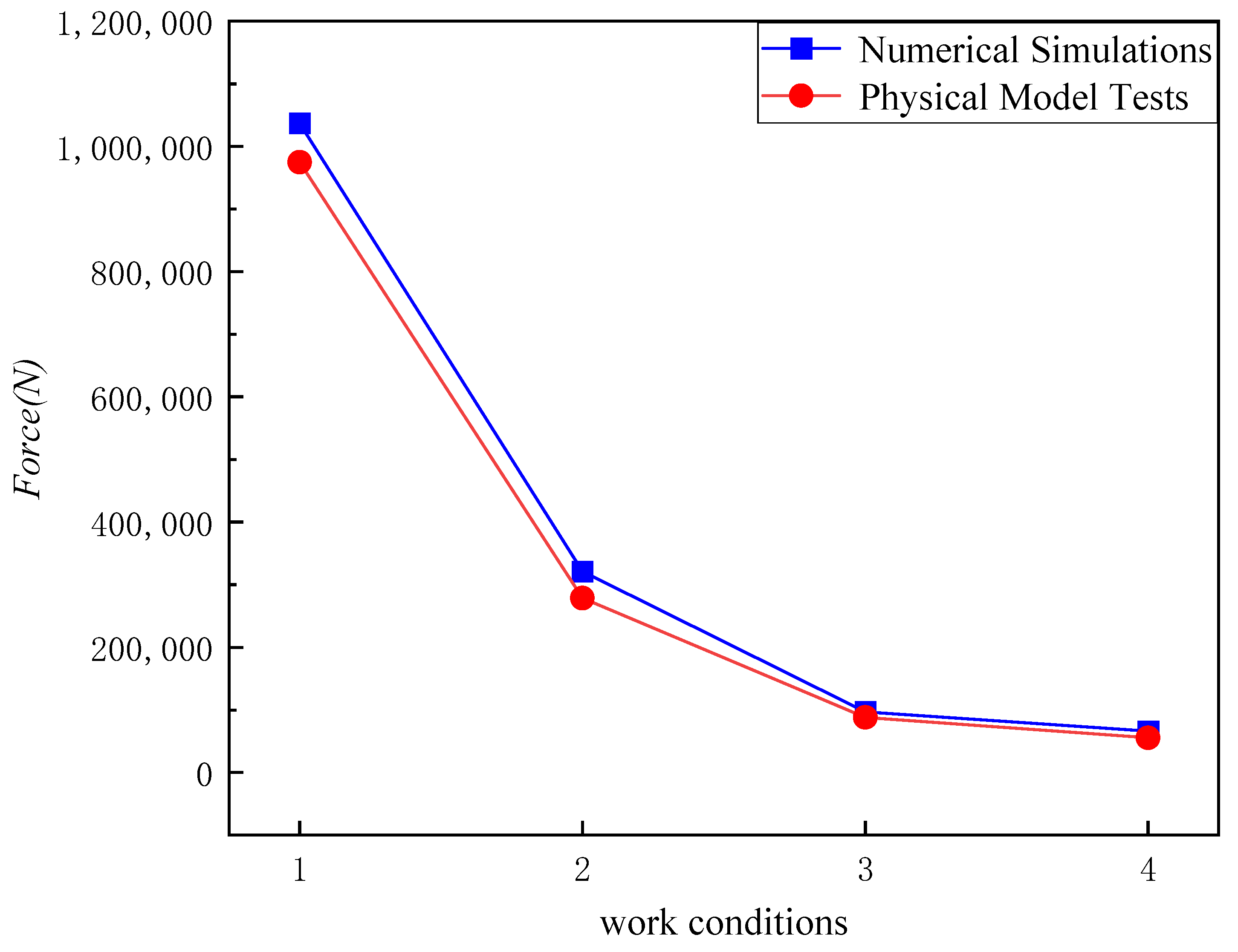
- The feasibility of the numerical simulation method when studying the impact mitigation effect of artificial backfill layers on seabed pipelines was verified through the rock pile angle case study and four corresponding example cases based on the physical model conditions. The simulation results show that the increase in safety factor exhibits a linear relationship with the thickness of the artificial backfill layer. Additionally, the dynamic response of the rock particles impacting the pipeline during the backfilling process is also significant and should not be overlooked.
- This study conducted physical model tests and numerical simulations to investigate the mitigation effect of the rock protection layer on pipeline impact. A series of conclusions was drawn to guide engineering applications. However, due to experimental constraints, the scale of the physical model tests was relatively small, making it difficult to accurately capture pipeline deformation. Additionally, in the numerical simulations, the irregular shape of the rock particles was not fully represented, which to some extent underestimated the mitigation effect of the protection layer. These limitations should be a key focus for improvement in future work.
Author Contributions
Funding
Institutional Review Board Statement
Informed Consent Statement
Data Availability Statement
Conflicts of Interest
References
- Dai, L.; Wang, D.; Wang, T.; Feng, Q.; Yang, X. Analysis and Comparison of Long-Distance Pipeline Failures. J. Pet. Eng. 2017, 2017, 3174636. [Google Scholar] [CrossRef]
- Liu, Y.; Hu, H.; Zhang, D. Probability Analysis of Damage to Offshore Pipeline by Ship Factors. Transp. Res. Rec. 2013, 2326, 24–31. [Google Scholar] [CrossRef]
- Li, J.H.; Kim, J.T.; Lee, M.J.; Jee, S.C.; Kang, H.J.; Kim, M.K.; Kwak, H.W.; Kim, S.B.; Oh, T.W. Water Jetting Arm Optimal Design Consideration for a ROV Trencher. In Proceedings of the OCEANS 2015—Genova, Genova, Italy, 18–20 May 2015; pp. 1–5. [Google Scholar]
- Atangana Njock, P.G.; Zheng, Q.; Zhang, N.; Xu, Y.-S. Perspective Review on Subsea Jet Trenching Technology and Modeling. J. Mar. Sci. Eng. 2020, 8, 460. [Google Scholar] [CrossRef]
- Fan, Z.; Yu, L.; Han, Y.; Yang, Q. Exploring Trench of Clay with Submerged Moving Circular Vertical Jet: Numerical Analysis. Ocean Eng. 2025, 319, 120216. [Google Scholar] [CrossRef]
- Hou, J.; Wei, W.R.; Liang, Y.; Chang, S.J.; Sun, Q.W. Outline of Rock Dumping Protection Engineering for Subsea Pipeline in Deepwater. New Technol. New Process 2015, 6, 79–82. (In Chinese) [Google Scholar]
- Yan, S.W.; Guo, B.C.; Sun, L.Q.; Lei, Z.M.; Liu, R. Mechanism and model tests on protection of submarine pipelines using rock armor berms. Chin. J. Geotech. Eng. 2014, 36, 2036–2044. [Google Scholar]
- Li, L.; Chen, Z.Y.; Wang, T.F.; Hu, H. Numerical Simulation Study on the Degree of Submarine Cable Protection by Rockfill Against Anchor. J. Civ. Eng. Manag. 2013, 30, 1–5. [Google Scholar]
- Zang, Z.P.; Xu, Z.; Zou, X.; Hou, J. Deformation response of a submarine pipeline with rock berm+concrete mattress protection subjected to impact by a drop-ping anchor. Ocean Eng. 2023, 41, 114–126. [Google Scholar]
- Li, Q.; Ma, K.M.; Wang, F.L.; Xiong, H.R.; Cui, S.M. Analysis of Resistance to Anchor Damage in Protection Design of Subsea Pipeline at Shipping Lanes. Shipbuild. China 2012, 54, 111–116. (In Chinese) [Google Scholar]
- Karamanos, S.A.; Eleftheriadis, C. Collapse of Pressurized Elastoplastic Tubular Members under Lateral Loads. Int. J. Mech. Sci. 2004, 46, 35–56. [Google Scholar] [CrossRef]
- Zhang, Y.P.; Zhang, C.H.; Zang, Z.P.; Xu, Y.J.; Li, Q.W.; Xu, Z. Experimental study on the performance of different cover layers for protecting a submarine pipeline from a dropped anchor of the article. J. Water Harbor. 2020, 41, 140–147. [Google Scholar]
- Wang, Y.; Huang, J.; Li, L.W.; Deng, Z.Y.; Gu, Y.C. Study on the protection effect of the gravel layer in the channel area on submarine pipelines under hall anchor dropping conditions. Ocean Eng. 2024, 42, 179–189. [Google Scholar]
- Jiang, F.; Dong, S.; Zhao, Y.; Xie, Z.; Guedes Soares, C. Investigation on the Deformation Response of Submarine Pipelines Subjected to Impact Loads by Dropped Objects. Ocean Eng. 2019, 194, 106638. [Google Scholar] [CrossRef]
- Zeinoddini, M.; Arabzadeh, H.; Ezzati, M.; Parke, G.A.R. Response of Submarine Pipelines to Impacts from Dropped Objects: Bed Flexibility Effects. Int. J. Impact Eng. 2013, 62, 129–141. [Google Scholar] [CrossRef]
- Qiu, C.L.; Wang, J.; Yan, S.W. Coupled DEM-FEM analysis of submarine pipelines with rock armor berm under impact load. Chin. J. Geotech. Eng. 2015, 37, 2088–2093. [Google Scholar]
- DNV-RP-F107; Risk Assessment of Pipeline Protection. DNV: Høvik, Norway, 2019.
- Shin, M.-B.; Park, D.-S.; Seo, Y.-K. Response of Subsea Pipelines to Anchor Impacts Considering Pipe–Soil–Rock Interactions. Int. J. Impact Eng. 2020, 143, 103590. [Google Scholar] [CrossRef]
- Dassault Systèmes. ABAQUS 6.14 Documentation; Dassault Systèmes Simulia Corp.: Providence, RI, USA, 2014. [Google Scholar]
- Yu, J.; Zhao, Y.; Li, T.; Yu, Y. A Three-Dimensional Numerical Method to Study Pipeline Deformations Due to Transverse Impacts from Dropped Anchors. Thin-Walled Struct. 2016, 103, 22–32. [Google Scholar] [CrossRef]
- Jiang, F.; Zhao, E. Damage Mechanism and Failure Risk Analysis of Offshore Pipelines Subjected to Impact Loads from Falling Object, Considering the Soil Variability. Mar. Struct. 2024, 93, 103544. [Google Scholar] [CrossRef]
- Jiang, F.; Zhao, E. A Study on the Failure Mechanism of Offshore Pipelines with Corrosion Defects Subjected to Impact Loads from Falling Objects. Ocean Eng. 2025, 318, 120119. [Google Scholar] [CrossRef]
- Jiang, F.; Dong, S. Development of a CNN-Based Integrated Surrogate Model in Evaluating the Damage of Buried Pipeline under Impact Loads, Considering the Soil Spatial Variability. Reliab. Eng. Syst. Saf. 2025, 257, 110801. [Google Scholar] [CrossRef]
- Hou, F.; Chen, Y.; Yan, Y.; Liu, R.; Li, R.; Liu, Y.; Zhong, R. Structural Response and Damage Assessment Method for Subsea Pipe-in-Pipe Subjected to Anchor Impact. Mar. Struct. 2025, 99, 103714. [Google Scholar] [CrossRef]
- Han, C.C.; Chen, X.J.; Liu, J. Model tests on penetration depth of hall anchor. Ocean Eng. 2018, 36, 90–98. [Google Scholar]
- GB/T 546-2016; Hall Anchors. Standards Press of China: Beijing, China, 2016.
- Wang, Y.; Ai, J.; Yang, Q. CFD-DEM coupled method incorporating soil inter-particle rolling resistance. Yantu Lixue/Rock Soil Mech. 2017, 38, 1771–1780. [Google Scholar]
- Li, T.; Xie, P.; Chang, J.; Chen, X. Rock-Pipeline Impact Force and Pipeline Response during Deep-Water Rock Dumping Operation. Mar. Struct. 2022, 84, 103235. [Google Scholar] [CrossRef]





| Object Shapes | Added Mass Coefficients, Ca |
|---|---|
| Elongated objects | 0.1–1.0 |
| Box-shaped | 0.6–1.5 |
| Complex shapes (spherical or complex bodies) | 1.0–2.0 |
| Object Shapes | Flat and Elongated | Box-Shaped | Complex Shapes (Spherical or Complex Bodies) |
|---|---|---|---|
| Drag coefficient, CN | 0.7–1.5 | 1.2–1.3 | 0.6–2.0 |
| Physical Quantity | Geometric Dimensions (L) | Density () | Acceleration (a) | Time (t) | Volume (V) | Impact Force (F) | Velocity (v) | Penetration Depth (z) | Kinetic Energy (EE) | Potential Energy (Ep) |
|---|---|---|---|---|---|---|---|---|---|---|
| Unit | m | kg/m3 | m/s2 | s | m3 | N | m/s | m | J | J |
| Symbol | ||||||||||
| Relation | 1 | 1 |
| Hall Anchor Dimensions λL = 15 | Weighs (kg) | H | h | h1 | L | L1 | B | B1 | H1 | I | J |
|---|---|---|---|---|---|---|---|---|---|---|---|
| Prototype dimensions | 15,400 | 4056 | 2199 | 483 | 3126 | 2199 | 1220 | 1446 | 680 | 498 | 150 |
| Model dimensions | 4.56 | 270 | 146.6 | 32 | 208 | 146 | 81 | 96 | 45 | 33 | 10 |
| Trench Shape | Prototype Rock Sizes | Scale Ratio | Scaled Dimensions |
|---|---|---|---|
| 4 m | 30~45 mm | 15 | 2~3 mm |
| 150~225 mm | 10~15 mm | ||
| 330~450 mm | 22~30 mm |
| Anchor Shape | Anchor Weight (kg) | Three Times the Concrete Compressive Strength Y (MPa) | Width of the Impacting Object b (m) | Length of the Impacting Object h (m) | Penetration Depth x0 (mm) | Ek (KJ) |
|---|---|---|---|---|---|---|
| Hall anchor | 15,400 | 105 | 1.22 | 3.126 | 40 | 870 |
| Anchor Weight (kg) | Prototype Maximum Fall Velocity (m/s) | Added Mass Coefficient | Maximum Impact Energy EE | Ek/EE |
|---|---|---|---|---|
| 15,400 | 8.172 | 5.11 | 851.8 KJ | 1.02 |
| Anchor Weight (kg) | Prototype Maximum Fall Velocity (m/s) | Velocity Scale Ratio λv | Model Maximum Fall Velocity (m/s) | Anchor Drop Height H |
|---|---|---|---|---|
| 15,400 | 8.172 | 3.873 | 2.11 | 0.227 |
| Condition Number | Protection Layer and Bedding Layer Condition | Anchor Drop Height H (m) | Anchor Weight (g) |
|---|---|---|---|
| H0 | No backfill protection layer | 0.227 | 4560 |
| H1 | 13 cm large particle size rock | ||
| H2 | 3 cm small particle size fine sand and 10 cm large particle size rock layered protection layer | ||
| H3 | 26 cm large particle size rock protection layer | ||
| H4 | 26 cm medium particle size rock protection layer | ||
| H5 | 3 cm small particle size fine sand, 10 cm medium particle size, and 13 cm large particle size rock layered protection layer | ||
| H6 | Soft mud bedding layer with 13 cm large particle size rock protection layer | ||
| H7 | Soft mud bedding layer with 3 cm small particle size fine sand and 10 cm large particle size rock protection layer | ||
| H8 | Sandy soil bedding layer with 13 cm large particle size rock protection layer | ||
| H9 | Sandy soil bedding layer with 3 cm small particle size fine sand and 10 cm large particle size rock protection layer | ||
| H10 | High-strength clay layer with 13 cm large particle size rock protection layer | ||
| H11 | High-strength clay layer with 3 cm small particle size fine sand and 10 cm large particle size rock protection layer |
| Condition Number | Rock Particle Size | Protection Layer Thickness | Remarks |
|---|---|---|---|
| N0 | 0.2 | - | Rock repose angle verification |
| N1 | - | - | Anchor directly impacts the pipeline and a comparison is made with the physical model test. |
| N2 | 0.4 | 4 m | Joint analysis of the impact of rock particle size and protection layer thickness on anchor impact buffering effect, and comparison with the physical model test. |
| N3 | 0.4 | 2 m | |
| N4 | 0.2 | 4 m |
Disclaimer/Publisher’s Note: The statements, opinions and data contained in all publications are solely those of the individual author(s) and contributor(s) and not of MDPI and/or the editor(s). MDPI and/or the editor(s) disclaim responsibility for any injury to people or property resulting from any ideas, methods, instructions or products referred to in the content. |
© 2025 by the authors. Licensee MDPI, Basel, Switzerland. This article is an open access article distributed under the terms and conditions of the Creative Commons Attribution (CC BY) license (https://creativecommons.org/licenses/by/4.0/).
Share and Cite
Jiang, G.; Yu, L.; Han, Y.; Hu, C.; Zhang, D.; Yang, Q. Study on the Impact Mitigation Effect of Artificial Rock Backfill Layers for Submarine Pipelines Based on Physical Model Tests and Numerical Simulations. Oceans 2025, 6, 22. https://doi.org/10.3390/oceans6020022
Jiang G, Yu L, Han Y, Hu C, Zhang D, Yang Q. Study on the Impact Mitigation Effect of Artificial Rock Backfill Layers for Submarine Pipelines Based on Physical Model Tests and Numerical Simulations. Oceans. 2025; 6(2):22. https://doi.org/10.3390/oceans6020022
Chicago/Turabian StyleJiang, Guixi, Long Yu, Yunrui Han, Chunhong Hu, Dayong Zhang, and Qing Yang. 2025. "Study on the Impact Mitigation Effect of Artificial Rock Backfill Layers for Submarine Pipelines Based on Physical Model Tests and Numerical Simulations" Oceans 6, no. 2: 22. https://doi.org/10.3390/oceans6020022
APA StyleJiang, G., Yu, L., Han, Y., Hu, C., Zhang, D., & Yang, Q. (2025). Study on the Impact Mitigation Effect of Artificial Rock Backfill Layers for Submarine Pipelines Based on Physical Model Tests and Numerical Simulations. Oceans, 6(2), 22. https://doi.org/10.3390/oceans6020022


