Abstract
Current trends show that wind turbines are growing in size to meet a rising demand for renewable energy generation, and their upscaled rotors have inherently become more flexible to maintain a proportionally lighter design. This is because larger rotors must be less massive relative to their diameter to minimize the levelized cost of energy (LCOE), which means that blades that are notably less stiff are produced as a result. These structural changes to blades are often reflected in their compromised aeroelastic stability and amplified deformation during operation, which has the potential to decrease the blade’s expected lifetime and the performance of the machine overall. Variations in blade flexibility are also known to influence vortex-wake structures downstream of the turbine, causing patterns of velocity deficit to evolve in ways that affect the performance of other turbines in the farm. This research explores how the increased flexibility of modern utility-scale wind turbine blades influences rotor aeroelastic behavior and interactions with farm flow. High-fidelity simulations of Sandia National Laboratories’ (SNL) National Rotor Testbed (NRT) wind turbine are presented. Flexible variations of the NRT baseline blade are simulated in a variety of realistic operational conditions typically expected at the SNL’s SWiFT facility in Lubbock, Texas. Solutions are then compared to investigate how specific changes to the structural properties of the NRT baseline blade’s design and construction can influence its aeroelastic response at the rotor and the evolution of the turbine’s wake.
1. Introduction
This research explores how the increased flexibility of modern utility-scale wind turbine blades influences rotor aeroelastic behavior and interactions with farm flow. Current trends show that wind turbines are growing in size to meet a rising demand for renewable energy generation [1], and their upscaled rotors have inherently become more flexible to maintain a proportionally lighter design [2]. This is because larger rotors must be less massive relative to their diameter to minimize the levelized cost of energy (LCOE), which produces blades that are notably less stiff as a result [3,4]. Consequently, these changes to the structure of modern utility-scale turbines blade are often reflected in their compromised aeroelastic stability and disproportionately amplified deformation during operation [5]. This increased sensitivity to fluctuations in aerodynamic forces and peak loads has the potential to decrease the expected lifetime and performance of the machine overall, if not properly accommodated for during operation [6,7]. Furthermore, variations in blade flexibility are known to influence the manner in which vortex-wake structures form in wind farm flow downstream of the turbine, causing patterns of velocity deficit to evolve in ways that greatly affect the performance of other turbines in the farm [5].
To optimize the performance and lifetime of highly flexible turbine blades, it is necessary to establish how increased rotor flexibility impacts the blade’s structural response to aerodynamic loading and other flow interactions during operation, and how this compares to what is already known about previous turbine models that operated at a much smaller scale [8]. The altered structural characteristics of modern upscaled blades lead to complex multi-physics reactions that are difficult to predict based on studies of wind turbines that are of an older design [9]. Due to the novel nature of the structural design of recently upscaled wind turbine blades, the dynamic relationship between blade stiffness and utility-scale wind turbine structural design must be further investigated to determine how the rigidity of specific features within a blade can alter its aeroelastic sensitivity to dynamic loading conditions. Furthermore, such enormous turbine rotors outsize the flow domain of even the largest currently available wind tunnel testing facilities [10], and the scale of size differences from previous models of wind turbines, prevents proper extrapolation of data from scaled-down wind tunnel testing. In respect of these challenges, a more feasible avenue of exploration is the use of numerical simulation approaches.
Most modern numerical methods require a large computational expense to simulate the behavior of such large, flexible blades with high fidelity. In most modeling approaches, a higher-fidelity solution usually accompanies a greater demand for computational resources. Thus, there are a variety of computational fluid dynamics techniques that offer a balanced trade-off between desired fidelity and required computational cost, ranging from simplified methods [11] to direct numerical simulation (DNS) [12]. Somewhere along this spectrum, you can find popular techniques that are often used to simulate wind turbine operation, like large eddy simulation (LES) [13,14,15,16] and Reynolds-averaged Navier–Stokes (RANS) modeling methods [17,18,19,20]. Although on the higher-fidelity end of the spectrum, requiring more computational resource, LES models tend to be the most common methodology used for wind farm flow simulation in recent work [21,22].
Alternative wind turbine modeling approaches couple fluid-flow dynamics with a structural blade model, which are often integrated through reduced-order computations of wind turbine rotor flow using variations of the blade element momentum (BEM) model (for more details about the classical BEM theory, see Burton et al. [23] and Manwell et al. [24]). Exploitation of this technique offers a robust characterization of interactions between fluid flow and oscillatory blade responses, and can be adapted to users constraints of fidelity level and cost of computation.
In this work, numerical simulations are performed using the Common Ordinary Differential Equation Framework (CODEF), introduced and validated in Ponta et al. [25]. CODEF is a particularly valuable tool for the scope of this research because it presents the unique ability of generating a high-fidelity, moderate-order solution that characterizes turbine aeroelastic behavior and wake-structure interactions at a computational cost much lower than current high-fidelity LES and RANS solutions. CODEF operates by evaluating many multi-physics calculations simultaneously, in timestep iterations, to form a common solution that defines the wind farm flow. Through an advanced implementation of the BEM technique, the Dynamic Rotor Deformation–Blade Element Momentum (DRD-BEM) and Generalized Timoshenko Beam Model work together to calculate the structural response and aeroelastic behavior of the rotor during operation, and the Gaussian Vortex Lattice Model (GVLM) characterizes wind farm vortex-wake structures and their interactions with downstream atmospheric flow.
This study provides a high-fidelity analysis of the influence of blade structure and design, in relation to the aeroelastic behavior and flow interaction from turbines of modern utility-scale design with variable stiffness. With the aim of assessing the qualitative and quantitative effects of changes to targeted features of the blade’s physical and structural design, several flexible variations of a baseline blade were made with reference to the National Rotor Testbed (NRT) wind turbine (see Kelley [26]), designed to be located and tested at the Scaled Wind Farm Technology (SWiFT) facility of Sandia National Laboratories (SNL) in Lubbock, Texas (see Kelly and Ennis [27], Berg et al. [28], and Barone and White [29]). This particular wind turbine model is most appropriate for this purpose because it was designed with the intent of investigating flexible properties of large wind turbine blades at a proportionally smaller scale to reduce overall computational expense. Flexible variations of the NRT baseline blade are simulated in a variety of realistic operational conditions typically expected at the SWiFT facility. The solutions are then compared to investigate how specific changes to the structural properties of the NRT baseline blade’s design and construction can influence its aeroelastic response at the rotor and the evolution of the turbine’s wake.
2. The Common ODE Framework
This section presents a brief description of the Common Ordinary Differential Equation Framework (CODEF) [25], and a description of how is it is utilized to simulate wind turbine and wind farm dynamics. In this study, CODEF is used to evaluate solutions for blade structure, aeroelastic behavior, and vortex-wake evolution. Here, we will discuss the basic structure of the CODEF model and its primary modules that are relevant to this research work. More details about CODEF, and its aeroelastic modules and validation tests can be found in Ponta et al. [25].
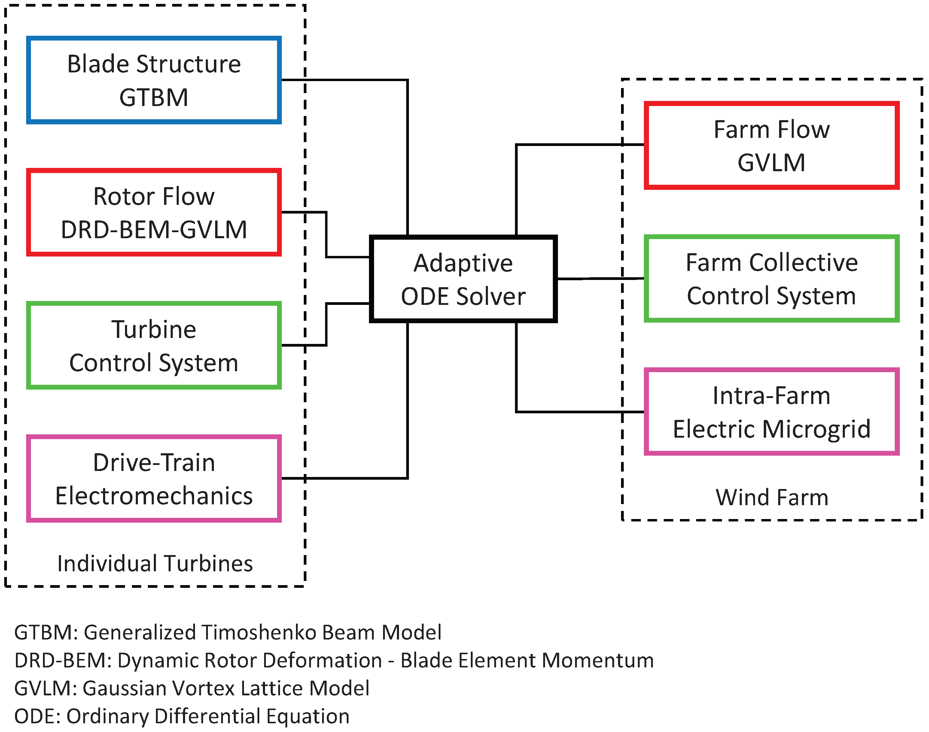
The CODEF model consists of a suite of inter-dependent modules, each containing subroutines which work together to form a variable-order/variable-timestep ODE solver that evaluates dynamic turbine operation. These modules cooperatively interact with a central-adaptive, nonlinear ODE solver that monitors the local truncation error at each timestep. Regulating truncation errors helps to maintain an efficient and stable progression of numerical evaluation, as the multi-physics modules are simultaneously integrated in successive, time-iterative steps. The modular nature of CODEF enables custom integration of dynamic components that model turbine controls, electro-mechanical devices, blade structure, rotor and farm flow, and more. Each module imposes characteristic boundary conditions and differential equations to define requisite interactions with the centralized CODEF feedback system. Figure 1 provides a visualization of the modular CODEF structure, showing how the interrelated system components enable the control and simulation of wind turbines at an individual and farm-collective level.
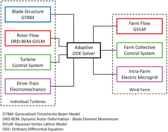
Figure 1.
Adaptive, interconnected structure of the Common ODE Framework suite.
In the following Section 2.1 and Section 2.2, we describe the implementations of the CODEF modules: the Dynamic Rotor Deformation–Blade Element Momentum (DRD-BEM), the Generalized Timoshenko Beam Model (GTBM), and the Gaussian Vortex Lattice Model (GVLM).
2.1. Aeroelastic Modules of CODEF
This section describes the DRD-BEM module implemented in CODEF, and its structural counterpart GTBM, which operate as a coupled model of the blade’s aerodynamic and structural response [25]. The classic BEM model approach calculates blade forces by evaluating the change in momentum as stream-tube fluid flow passes through a theoretical actuator disk aligned with the rotor plane. One of the shortcomings of this basic implementation of the BEM model is that it does not account for misalignments of blade sections with respect to the incident flow due to deformation occurring during turbine operation. In certain atmospheric conditions, these changes to blade morphology and aerodynamic attitude are substantial; therefore, neglecting to model them will result in inaccurate calculations of wind turbine aeroelastic behavior.
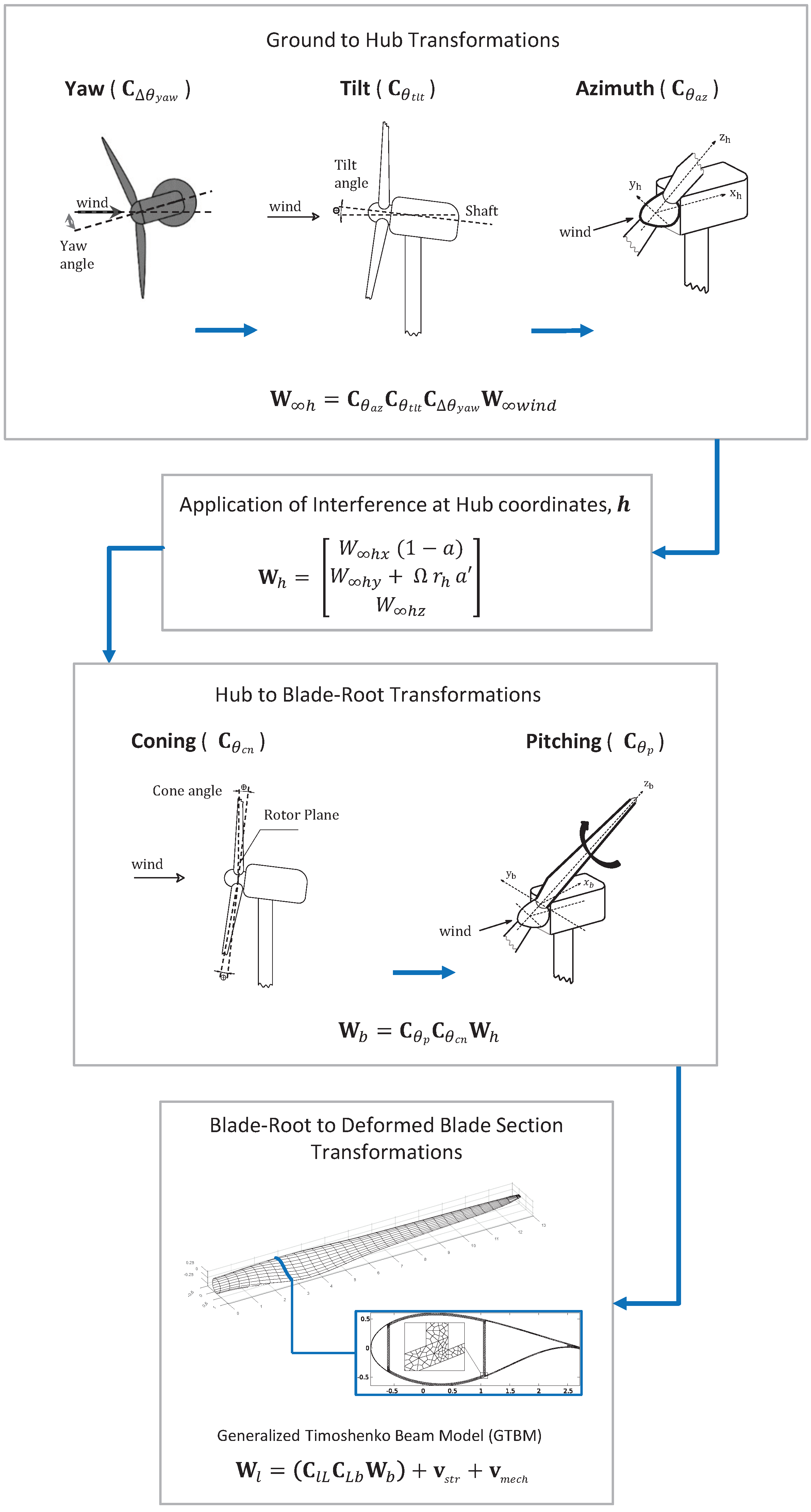
In CODEF, the DRD-BEM model incorporates the effects of these misalignments due to structural changes to blade attitude during operation. The DRD-BEM model evaluates the aerodynamic forces at deformed blade sections by transforming the incoming wind velocity, , to the coordinate system of deformed blade sections, l, using orthogonal-matrix linear operators, as shown in Figure 2.
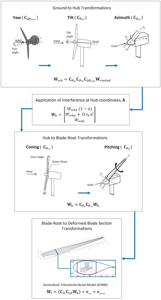
Figure 2.
Schematic representation of the sequence of coordinate transformations via orthogonal-matrix linear operators used by DRD-BEM.
In the DRD-BEM model, the coordinate transformations begin by projecting the incoming freestream inflow, , into the hub coordinate system, h. To account for the alignment of the rotor hub relative to the oncoming wind, the following linear operators are adjusted to represent the misalignment due to instantaneous yaw offset , tilt , and angle of azimuth .
Axial and tangential induction factors a and can then be applied to incorporate the effects of interference at the h coordinate system.
A series of linear operators accounting for misalignments, due to coning and pitch , are applied to transform into the blade-root coordinate system, b. From there, and transform blade-root coordinates to the deformed blade-section coordinates l, derived from structural evaluations of blade warping during operation. Velocity components associated with blade-section structural vibrations, , and mechanical actions, , can also be added in the coordinate system of the deformed blade sections.
The total aerodynamic load for a blade element section, , is calculated based on aerodynamic lift and drag coefficients corresponding to the blade section’s instantaneous alignment with the relative wind direction. The linear operator then projects components of lift and drag onto the chord-normal and chord-wise directions, with respect to the l coordinate system. We can express the total aerodynamic load acting on a blade element section in the h coordinate system, , by projecting back to the hub coordinates via the inverse of the same linear operators (i.e., the transpose of their original orthogonal matrices):
Then, the axial and tangential components of are used to obtain the a and interference factors as in the traditional BEM method [23,24]. The axial and tangential projections of the hub forces exerted at the root of each blade are also added together to compute the total thrust and torque of the rotor. The rotor power is then obtained by the product of the torque and the hub’s rotational speed.
Complete details about the DRD-BEM formulation, including a full mathematical derivation, can be found in Ponta et al. [25], together with results of the DRD-BEM model applied to the analysis of vibrational modes of composite laminated wind turbine blades, and validation results against the works of Jonkman et al. [30] and Xudong et al. [31].
Applications of the DRD-BEM to the solution of several diverse aeroelastic problems in wind turbine rotors can also be found in several references. Menon and Ponta [32] report results of the DRD-BEM applied to the analysis of the aeroelastic dynamics of rotors undergoing rapid pitch control actions, and Menon and Ponta [33] analyze the effects of flap control actions. Otero and Ponta [34] use the model to analyze the effects of blade-section misalignment on rotor cyclic loads. DRD-BEM is also used to study the effects of controlled gust pulses on rotor oscillatory response in Jalal et al. [35] and Jalal et al. [36], the response of adaptive blade designs in Lago et al. [37], and the rotor’s response in high-aerodynamic-interference conditions in Rajan and Ponta [38].
To model the structural dynamics of wind turbine blades, CODEF incorporates the Generalized Timoshenko Beam Model (GTBM), originally presented by Hodges et al. [39,40]. The GTBM serves to reduce the 3D structural analysis of the blade into a 1D, nonlinear computation of an equivalent beam, performed at each timestep of the aeroelastic analysis. Since wind turbine blades often have a heterogeneous material composition and unique structural features, the GTBM is necessary to give a more descriptive model than what classic beam models offer, which typically neglect to incorporate dynamic and kinematic variables that are influential in the blade’s response to aerodynamic loads.
In classic implementations of the classical Timoshenko method, the blade is represented by a beam of equivalent stiffness, evaluated at undeformed cross-sections along the blade’s span. One of the shortcomings of this approach is that it does not account for warping and misalignment of the blades during turbine operation. In certain atmospheric conditions, these changes in blade morphology and aerodynamic attitude are substantial; therefore, neglecting to model them is greatly detrimental to the accuracy of the method. In CODEF, the original Timoshenko hypothesis of beam sections remaining planar is abandoned. Thus, deformations of blade sections are interpolated from a 2D finite element mesh, and 3D strain energy is pre-solved in terms of the original 1D Timoshenko variables [41]. Through this dimensional reduction, the blade is represented as a structurally equivalent 1D beam with a fully populated stiffness matrix that contains all coupled deformation modes, like the flexo-torsional bend twist modes. For the case of the results presented in Section 3 of the present work, the 1D finite element model for the blade uses 37 one-dimensional spectral isoparametric beam elements of fourth order.
The formulation of GTBM is also inherently capable of representing the influence of large geometric deformation on the blade structural response (for more details about this aspect, the reader is referred to Hodges [39], Yu et al. [40], Otero and Ponta [41], Ponta et al. [25], and the several references within).
Ponta et al. [25], Otero and Ponta [41], and Otero et al. [9] include additional details about the coupling of DRD-BEM with the GTBM structural model, and their application to the analysis of vibrational modes of composite blades, which the reader might find interesting.
2.2. The Gaussian-Core Vortex Lattice Model
Introduced in Baruah and Ponta [42], the Gaussian-Core Vortex Lattice Model (GVLM) is a fluid-flow modeling technique that provides a high-fidelity solution for wind turbine and farm fluid-flow dynamics with a moderate computational cost. A brief description of the GVLM model is presented here in order to make this paper self-contained. For a comprehensive description of the GVLM’s theoretical foundations and its integration into the CODEF suite, the reader is referred to Baruah and Ponta [42]. The latter also includes a complete derivation of GVLM’s mathematical formulation, and a description of the algorithmic sequence for the generation of GVLM’s vortex lattice assemblies.
A series of validation tests can also be found in Baruah and Ponta [42], which compare wind turbine wake velocity patterns from LiDAR field measurements obtained at SNL’s SWiFT facility (as reported by Herges et al. [43]) with results obtained from GVLM simulations in the same operational conditions.
The GVLM works together with the DRD-BEM method to perform a detailed characterization of complex wind turbine vortex-wake evolution that is computationally efficient relative to alternative high-fidelity simulation techniques. The magnitude and angle of attack of the relative incident flow velocity is identified by the DRD-BEM model to characterize the circulation of fluid flow as it interacts with the wind turbine blade sections during operation. GVLM then exploits these span-wise evaluations of the incident flow velocity to calculate the circulation of the bound vortex filament at each blade section, using the Kutta–Jukowski lift theorem. By solving for the circulation of vortex filaments along the whole blade’s span at successive time-iterations of the CODEF solver, the GVLM generates a helical lattice of vortex filaments to model the wind turbine’s wake structure, in such a manner that satisfies both the Helmholtz and Kelvin theorems of conservation of circulation [44].
In this study, we use solutions of GVLM vortex lattice wake structures to project downstream velocity patterns induced by turbine wakes. The velocity induced at any point in a farm flow-field can be calculated based on the collective vorticity-filament contributions of the GVLM wake structure, using an adapted implementation of the free vortex lattice method from Ponta and Jacovkis [45] and Strickland et al. [46]. The CODEF GVLM differs from the classic representation of singularity concentration from the Biot–Savart law by utilizing filaments with Gaussian-core distributions of vorticity, which leverages several advantages. First, the viscous decay of the vortex wake occurs more naturally with time, in comparison to the simple singularity approach that will never decay [47]. Additionally, the viscous decay of the GVLM reduces computational costs, as it relieves the memory of vortices that have already dissipated. Gaussian-core distributions of vorticity also prevent unrealistic induction of tangential velocity within close radial proximity to the vortex core, which can occur in classic Biot–Savart singularity representations.
See Ponta [47], Batchelor [44], Trieling et al. [48], Flór and van Heijst [49], Lamb [50], and Hooker [51] for more information regarding vortex-core formation and Gaussian-core vorticity and velocity distributions.
For generalized discussions of free vortex lattice techniques and mechanisms of vortex-filament velocity induction, see Ponta and Jacovkis [45], Strickland et al. [46], Karamcheti [52], and Cottet and Koumoutsako [53].
3. Numerical Experimentation and Analysis of Results
This section describes the experimental approach of the study, and presents an analysis of simulated wind turbine operation from CODEF computations. The focus of this work involves the simulation of the National Rotor Testbed (NRT) baseline wind turbine and its flexible variations, in a diverse set of operating conditions. These efforts aim to characterize the nature in which wind turbine blade flexibility is related to the aeroelastic response of the rotor and the character of the resulting vortex-wake structure.
Using the aforementioned numerical approach discussed in Section 2, the NRT baseline blade was modeled within the Common ODE Framework, based on the descriptions of the blade provided by Sandia National Laboratories [26]. Factors such as the geometric, structural, and material properties of the blade design were all considered in the CODEF model to accurately match the physical properties detailed in the NRT blade documentation. After the initial baseline was modeled, several variations of the NRT blade were created by reducing the thickness of specific portions of the blade’s structure to alter the flexibility of the blade. The performance of these flexible variations of the NRT blade are compared to the baseline using CODEF numerical simulations of rotor aeroelastic response and vortex-wake interactions. The results of these computations are presented in this section for analysis and general discussion.
Simulations of wind turbine operation were performed for each flexible blade variation in differing atmospheric conditions, with and without yaw offset. The flow conditions simulated in this study were based on the typical wind observations from meteorological (MET) towers located at the Sandia National Laboratories (SNL) Scaled Wind Farm Technology (SWiFT) facility in Lubbock, TX [27,54]. The measurements indicate an average wind speed of 6 m/s at hub height in the SWiFT facility, which correlates to an ideal tip-speed ratio of 9 for the NRT turbine [26]. In all simulations discussed in this study, the hub height wind speed and tip-speed ratio remain constant at these values. Vertical directional wind shear (veer) is also kept constant at .
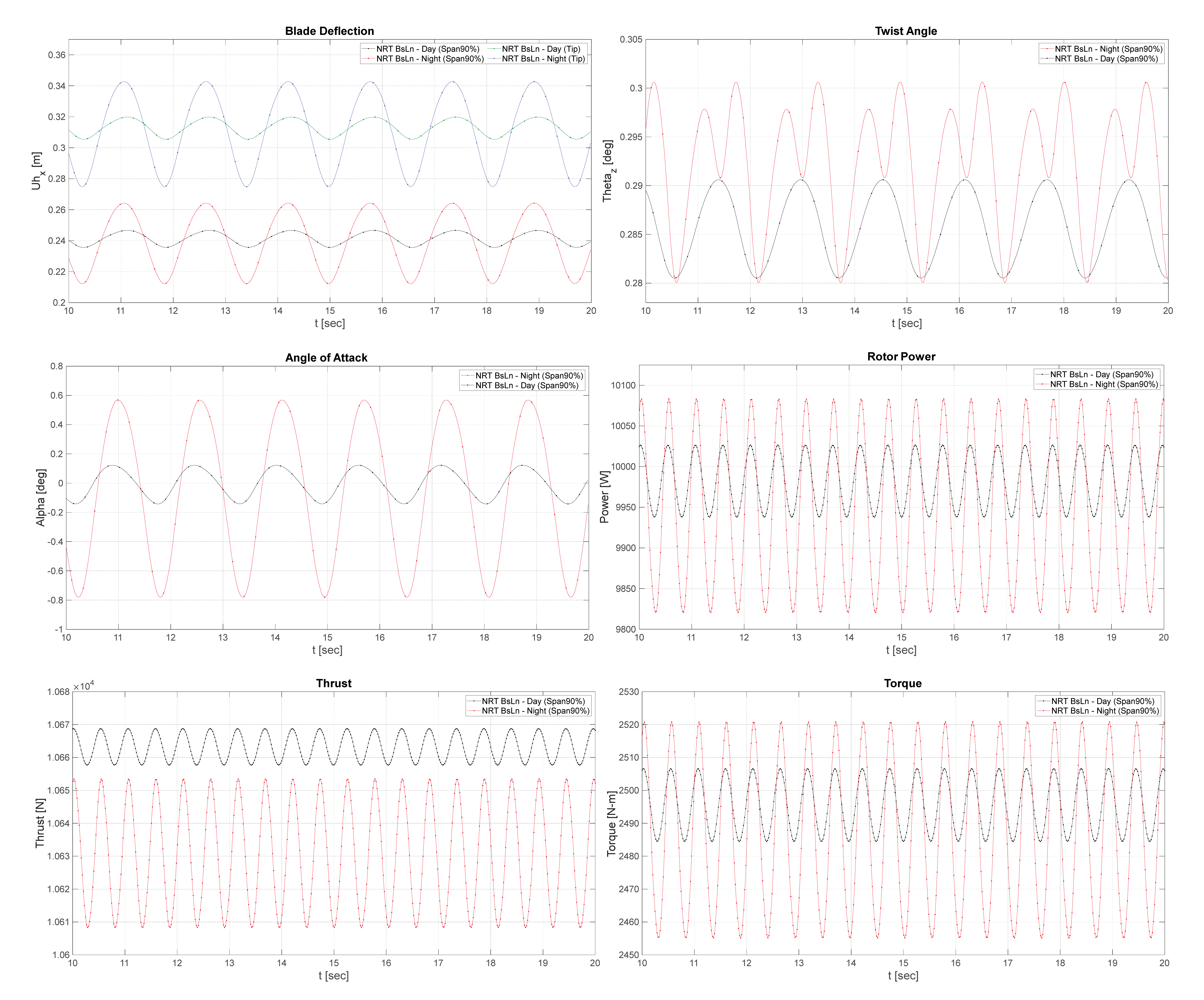
The simulated operational conditions presented for comparison in this work include typical daytime and nighttime conditions at SWiFT, with and without a yaw offset [27]. The measurements from the SWiFT facility indicate that typical daytime conditions have a shear exponent of 0.06 and a turbulence intensity (TI) of 18%. Typical nighttime conditions have a shear exponent of 0.3 and a TI of 8%. The simulated aeroelastic behavior of the baseline NRT blade during daytime and nighttime conditions is shown in Figure 3 below. These plots depict blade axial deflection at the blade tip and 90% span locations; torsional (twist) angle at 90% blade span; angle of attack at 90% blade span; and power, torque, and thrust at the hub.
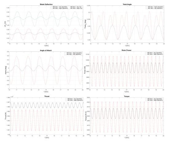
Figure 3.
Plots showing the time evolution of the NRT baseline blade operating in daytime and nighttime conditions, with no yaw offset.
It is important to note that the typical nighttime conditions indicate a more stably stratified flow relative to the daytime conditions [21,27]. The more stable nighttime atmospheric state inherently introduces a more dramatic shear profile, which causes a larger cyclical variation in aerodynamic loading across the rotor plane and effects within the vortex-wake structure as it propagates downstream [55,56]. Thus, differing aeroelastic oscillatory behavior can be expected from simulations of turbine operation in nighttime conditions. This effect can be observed in plots showing the aeroelastic response of the baseline NRT blade in Figure 3.
In the later Section 3.2 and Section 3.3, the effects of yaw offset are also explored. The introduction of a yaw offset can lead to a similar spatiotemporal variation in aerodynamic loading across the rotor plane, and cascading effects within the propagating vortex-wake structure [11,57]. To evaluate the interplay of these conditions within the scope of turbine aeroelastic behavior and wake dynamics, this study presents a comparison of the nighttime case with yaw offset to the daytime case with no yaw offset. This is shown to exemplify the most dichotomous operational conditions that are typically observed at the SWiFT facility in terms of inducing cyclical variation in aerodynamic loads at the rotor.
3.1. Aeroelastic Simulations of the NRT Blade Flexible Variations with Refined Geometry and Internal Structure
As an initial approach, several variations were created by reducing the scale of individual structural components of the NRT baseline blade to 80% of their original thickness. Some of these variations specifically targeted a reduction in the uniaxial-fiber composite (UNI) material within the blade, in order to evaluate its isolated influence. As an example, Figure 4 shows a schematic view of the typical internal components of the internal structure of a generic wind turbine blade. In this example, a box-beam spar structure is shown; alternative blade internal layouts may use an I-beam spar with only one shear web in the center of the spar connecting the two spar-cap layers.
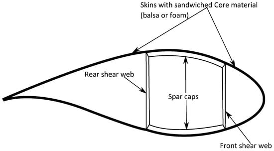
Figure 4.
Schematic view of the typical internal components of the internal structure of a generic wind turbine blade. In this example, a box-beam spar structure is shown.
A focus on a reduction to 80% of original baseline thickness was used to first establish the effects of these selected structural modifications, before investigating different combinations of percentage reductions in further analysis. The following variations were created as a result.
- (A)
- “BsLn” NRT baseline blade;
- (B)
- “80Sp” 80% adjustment of UNI material in spar cap;
- (C)
- “80Uni” 80% adjustment of all UNI material (spar cap and shell);
- (D)
- “80Sh” 80% adjustment of all shell material;
- (E)
- “80SpSh” 80% adjustment of all material (spar cap and shell).
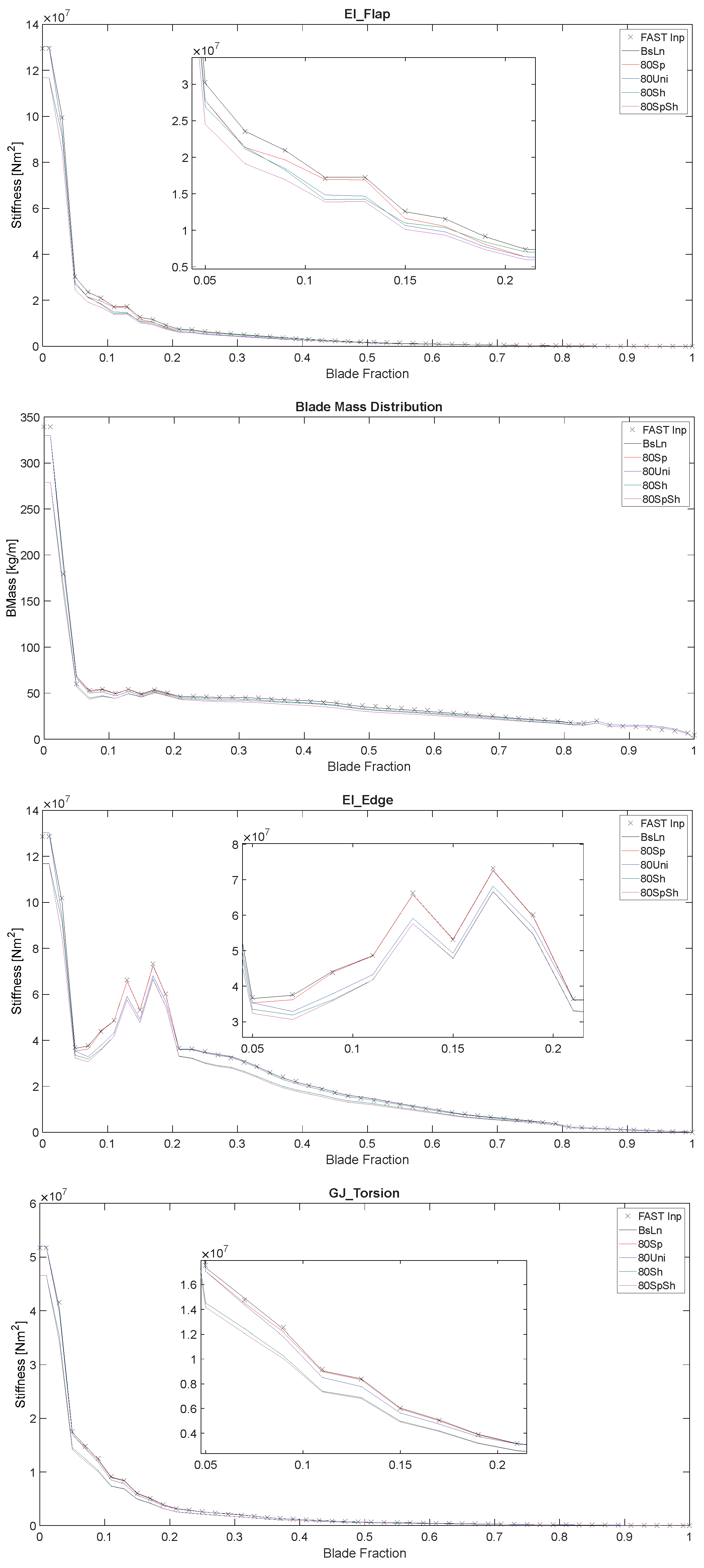
To determine the effects of the selected structural modifications to the baseline blade, the resulting changes in stiffness for each blade variation can be visualized along the blade’s span in Figure 5. The isolated structural contributions of the spar cap and shell materials can be identified by comparing the BsLn, 80Sh, and 80SpSh blade variations relative to each other. Similarly, the influence of specifically the UNI material in the spar cap and the UNI material in the shell can be determined by comparing the BsLn, 80Sp, and 80Uni variations.
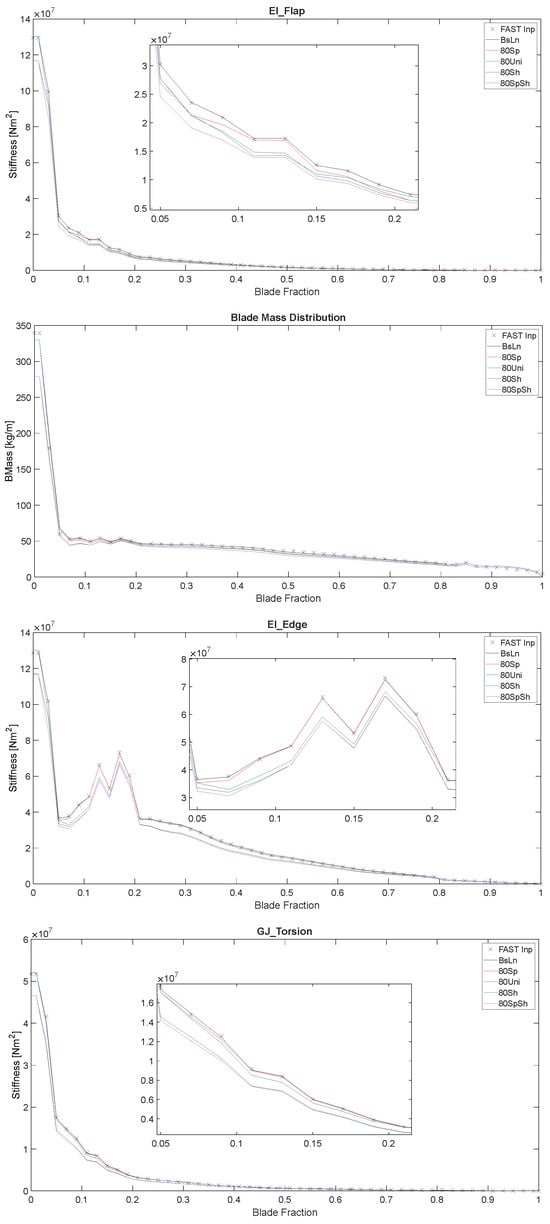
Figure 5.
Distributions of flap-wise stiffness, blade mass density, edge-wise stiffness, and torsional stiffness of the baseline NRT blade and 80% reduced variations, as computed by the GTBM process, plotted along the normalized blade span. Input FAST values (labeled “FAST Inp”) are also plotted for comparison.
The plots in Figure 5 show the normalized span-wise distributions of flap-wise stiffness, blade mass density, edge-wise stiffness, and torsional stiffness of the aforementioned 80% blade variations, modeled with CODEF. These distributed properties are computed as part of the dimensional reduction procedure of the GTBM model [39,40,41]. The values from the FAST documentation for the NRT baseline blade are also plotted for reference [26,58].
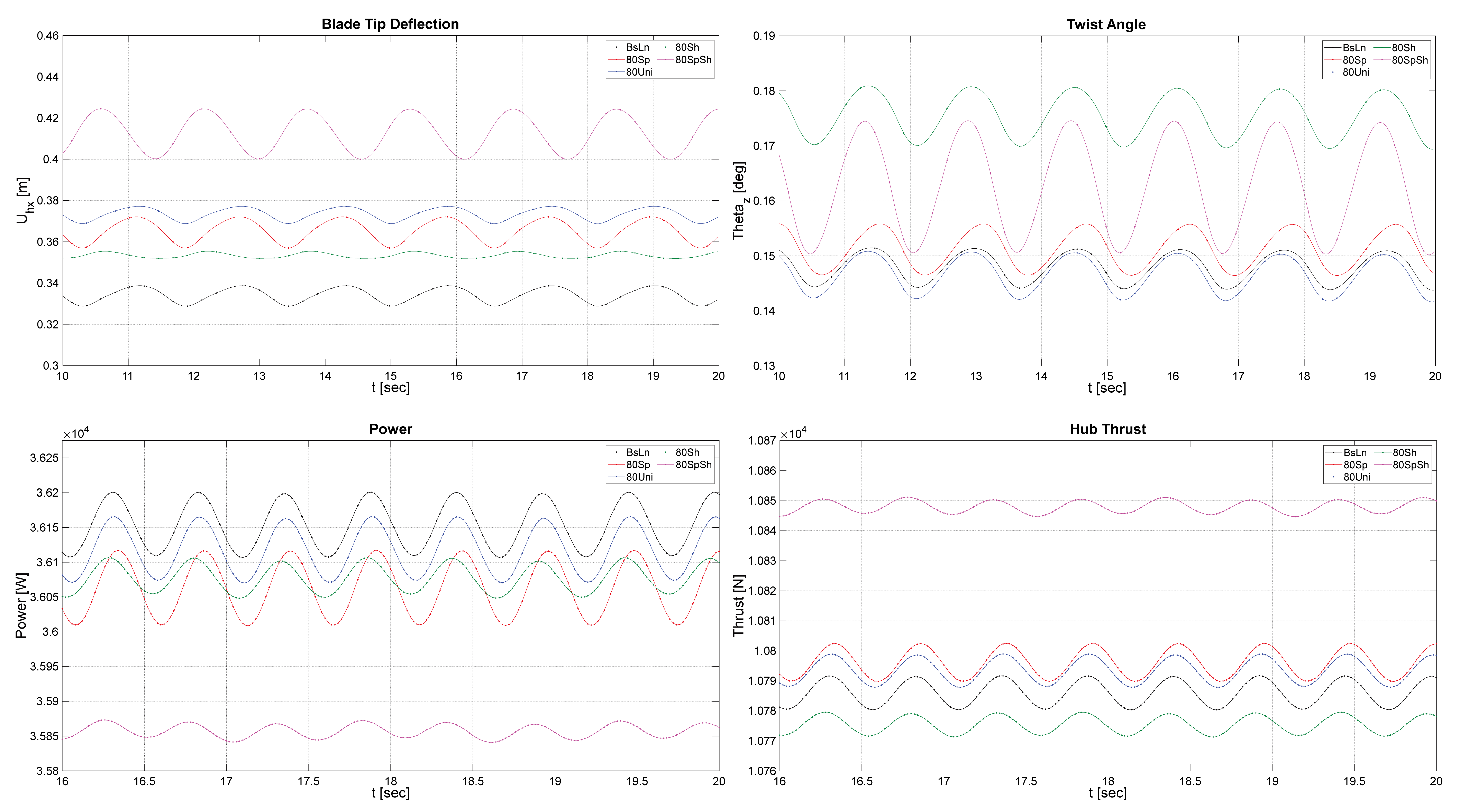
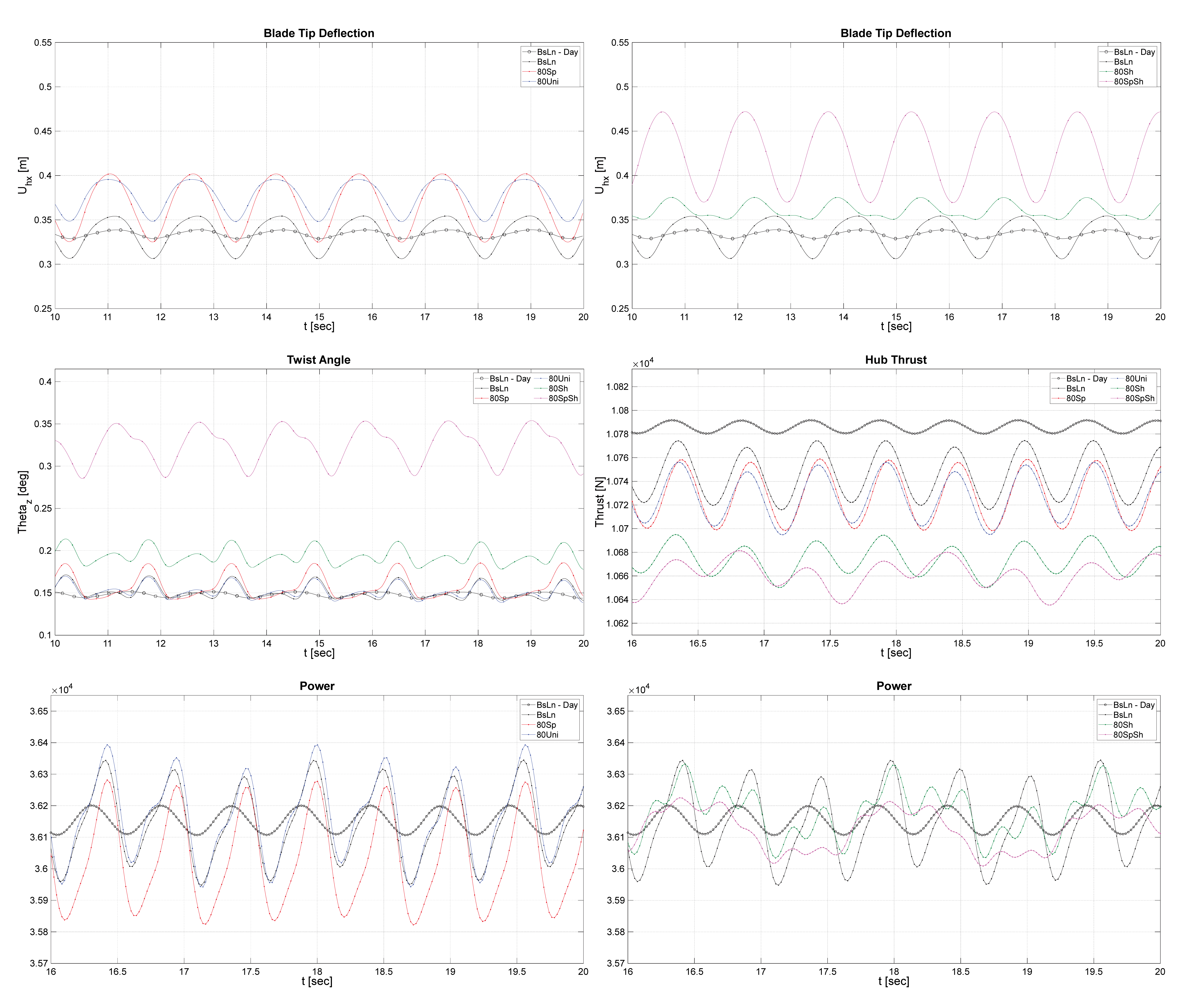
An aeroelastic analysis of blade response was also performed for the 80% reduced variations by using CODEF simulations. The plots shown in Figure 6 and Figure 7 show a comparison of the aeroelastic oscillatory behavior of a single blade on the baseline NRT rotor and the flexible variations, during daytime and nighttime conditions, respectively. These plots are intended to provide a basis for discussion regarding the aeroelastic behavioral changes that correspond to modifications to the structural composition and stiffness characteristics of the NRT baseline blade.
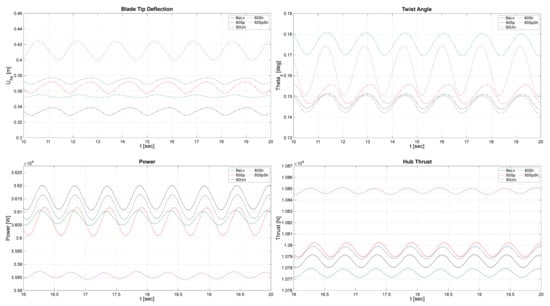
Figure 6.
Time evolution of blade-tip deflection, twist angle at 90% of the blade span, and power and thrust at the hub during typical daytime conditions.
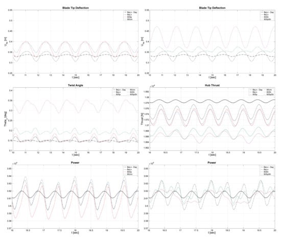
Figure 7.
Time evolution of blade-tip deflection, twist angle at 90% of the blade span, and power and thrust at the hub during typical nighttime conditions. The response of the BsLn blade in daytime conditions is also shown for reference.
3.2. Aeroelastic Simulations of Additional Flexible Variations of the NRT Blade
In the next stage of research, additional variations of the NRT baseline blade were created by further reducing all spar cap and shell materials to 60%, 40%, and 20% of their original baseline thickness. Different combinations of scaling factors were used so that the effects of the spar cap and shell modifications could be analyzed independently. The following variations were created.
- (A)
- “BsLn” NRT baseline blade;
- (B)
- “60%SpSh” 60% shell and spar cap materials;
- (C)
- “40%Sp–60%Sh” 40% spar cap and 60% shell materials;
- (D)
- “40%SpSh” 40% shell and spar cap materials;
- (E)
- “20%Sp–40%Sh” 20% spar cap and 40% shell materials;
- (F)
- “20%SpSh” 20% shell and spar cap materials.
This section will present analysis of these further reduced variations of the baseline blade, including results from numerical simulation of the blade’s aeroelastic behavior in a variety of operational conditions. In the following Section 3.3, simulations of wake-structure interactions are also provided for evaluation of their comparative performance in the context of wind farm flow velocity patterns.
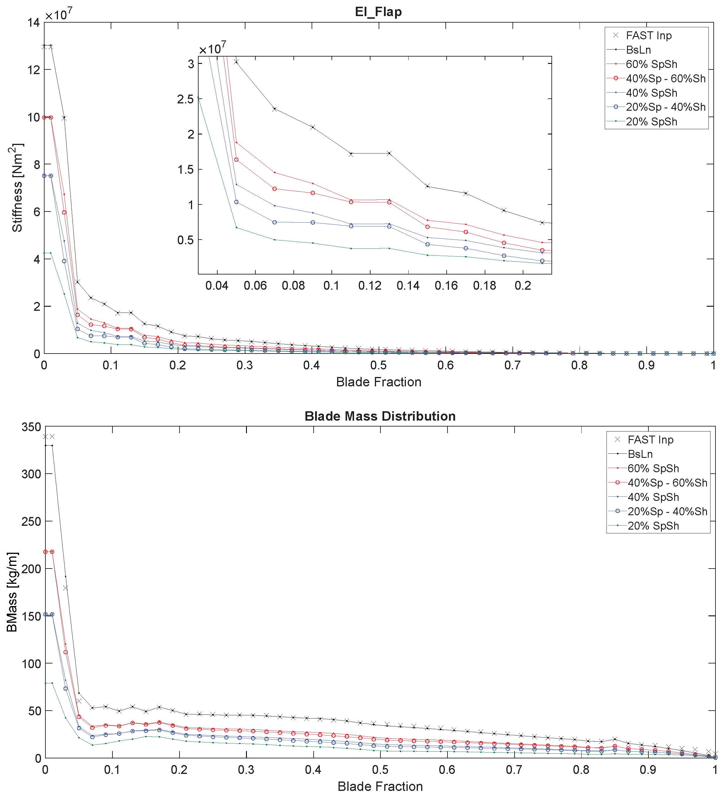
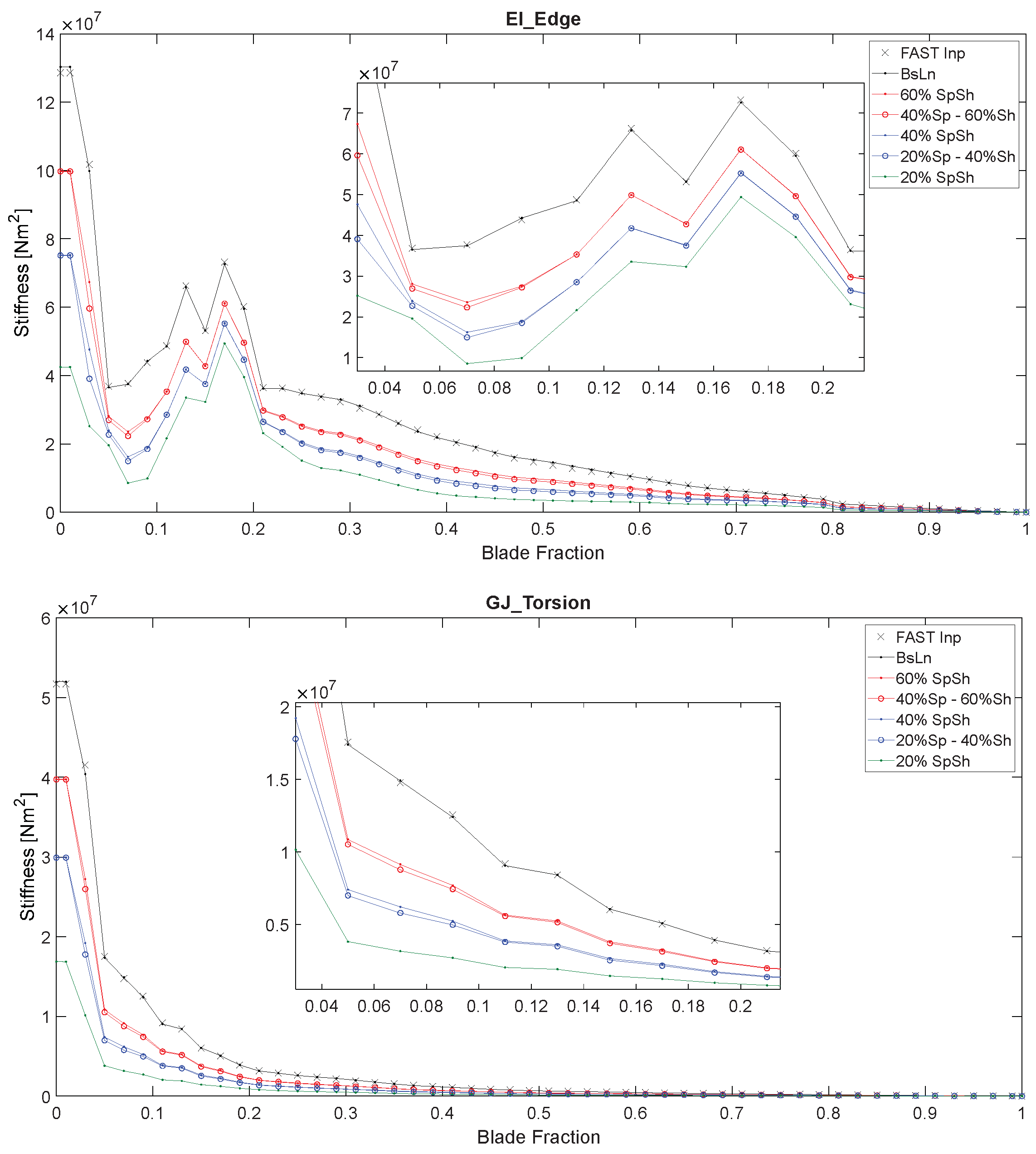
Table 1 lists the 60%, 40%, and 20% reduced blade variations, and their total mass in comparison to the baseline blade. Figure 8 provides the normalized span-wise distributions of flap-wise stiffness, blade mass density, edge-wise stiffness, and torsional stiffness modeled with CODEF. As before, these distributed properties are computed as part of the dimensional reduction procedure of the GTBM model [39,40,41]. The values from the FAST documentation of the NRT baseline blade are also plotted for reference [26,58].

Table 1.
Total mass of the NRT blade and its reduced thickness variations.
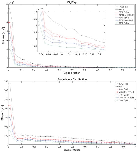
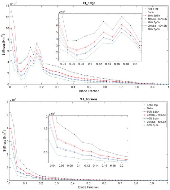
Figure 8.
Distributions of flap-wise stiffness, blade mass density, edge-wise stiffness, and torsional stiffness of the baseline NRT blade and its 60%, 40%, and 20% reduced variations, as computed by the GTBM process, plotted along the normalized blade span. Input FAST values (labeled “FAST Inp”) are also plotted for comparison.
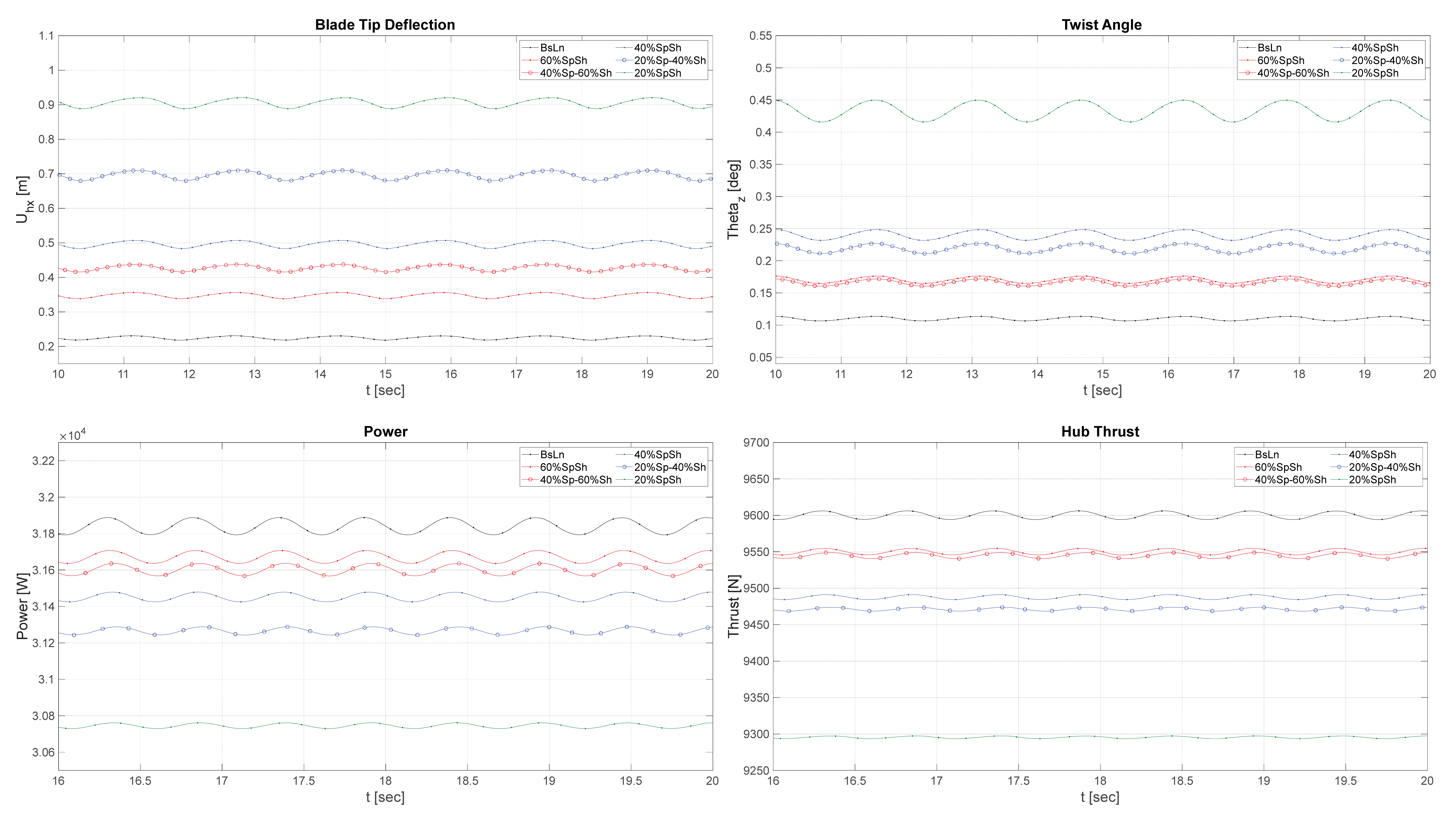
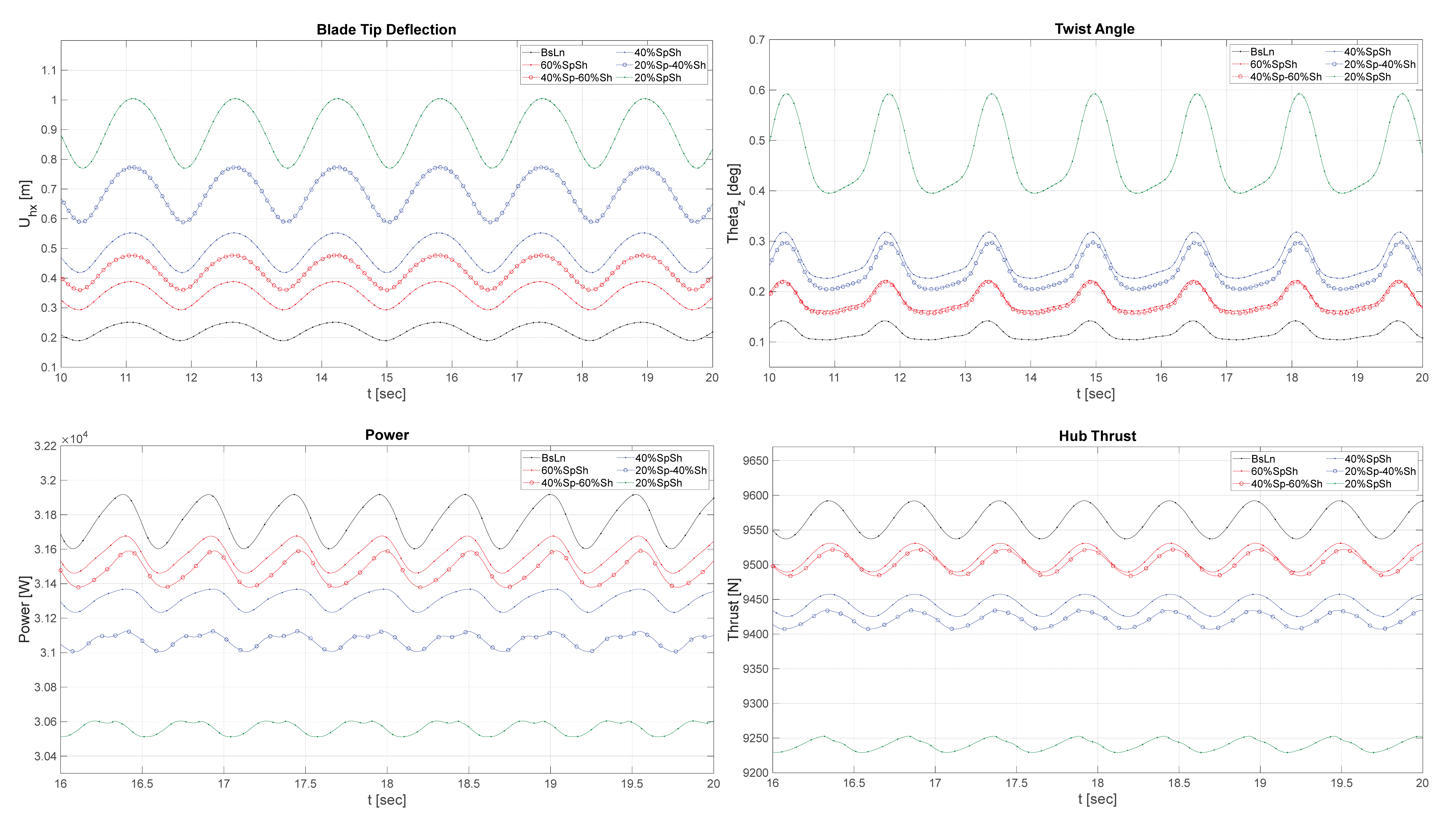
Figure 9, Figure 10, Figure 11 and Figure 12 that follow show aeroelastic simulations of the baseline NRT blade and its 60%, 40%, and 20% reduced variations in four different operating conditions of day and night, with and without yaw. These illustrate the time evolution of axial blade deflection at the tip, twist angle at 90% blade span, power, and thrust at the hub.
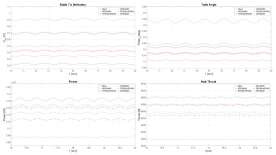
Figure 9.
Time evolution of blade-tip deflection, twist angle at 90% blade span, power, and thrust at the hub during typical daytime conditions, with yaw offset = .
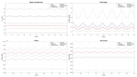
Figure 10.
Time evolution of blade-tip deflection, twist angle at 90% of the blade span, power, and thrust at the hub during typical daytime conditions, with yaw offset = .
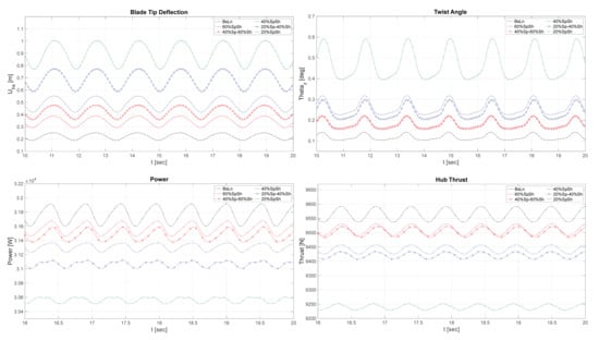
Figure 11.
Time evolution of blade-tip deflection, twist angle at 90% of the blade span, power, and thrust at the hub during typical nighttime conditions, with yaw offset = .
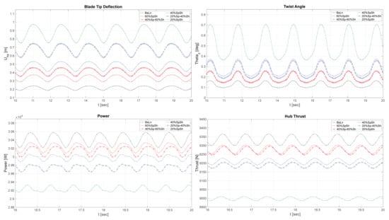
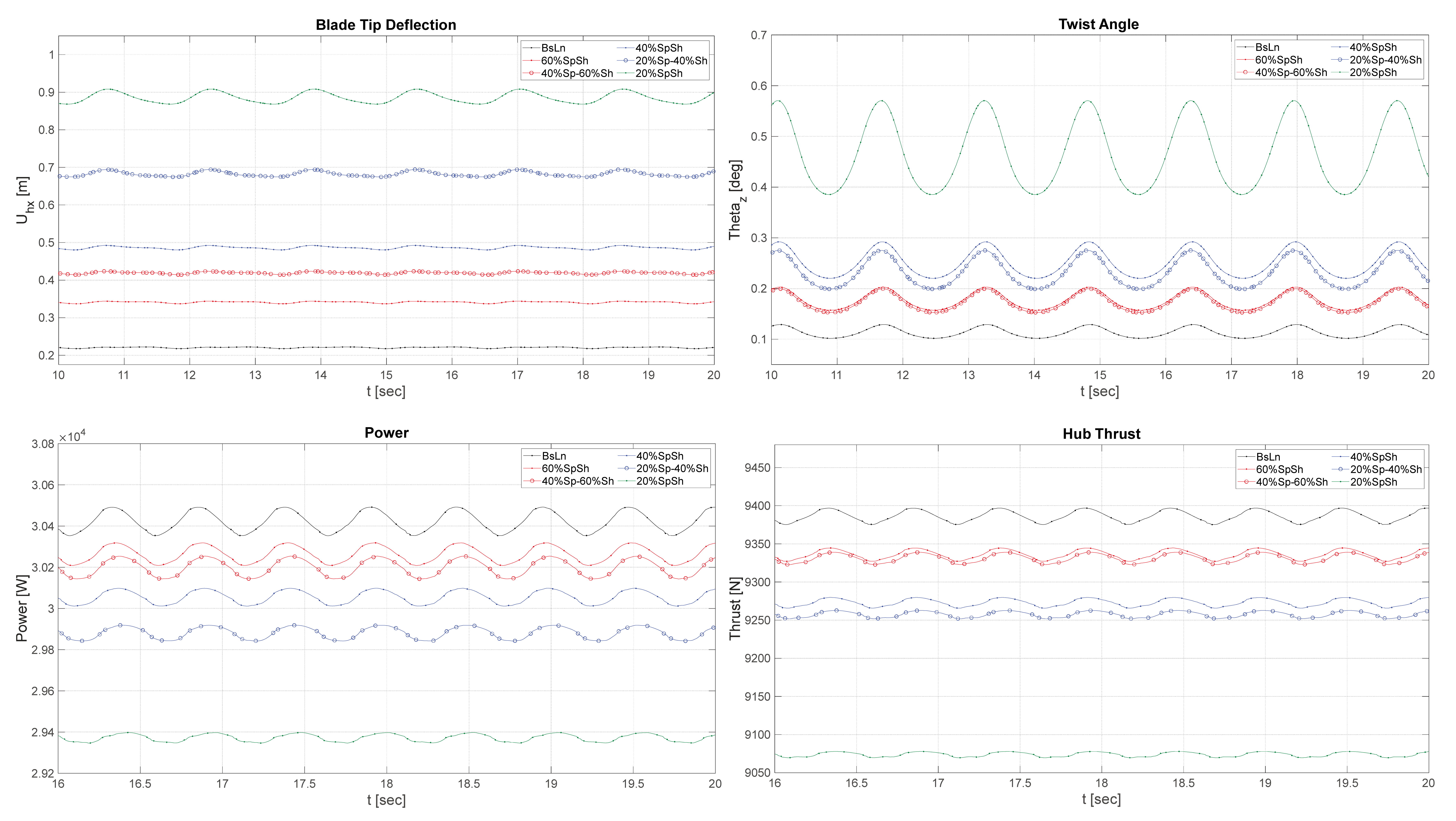
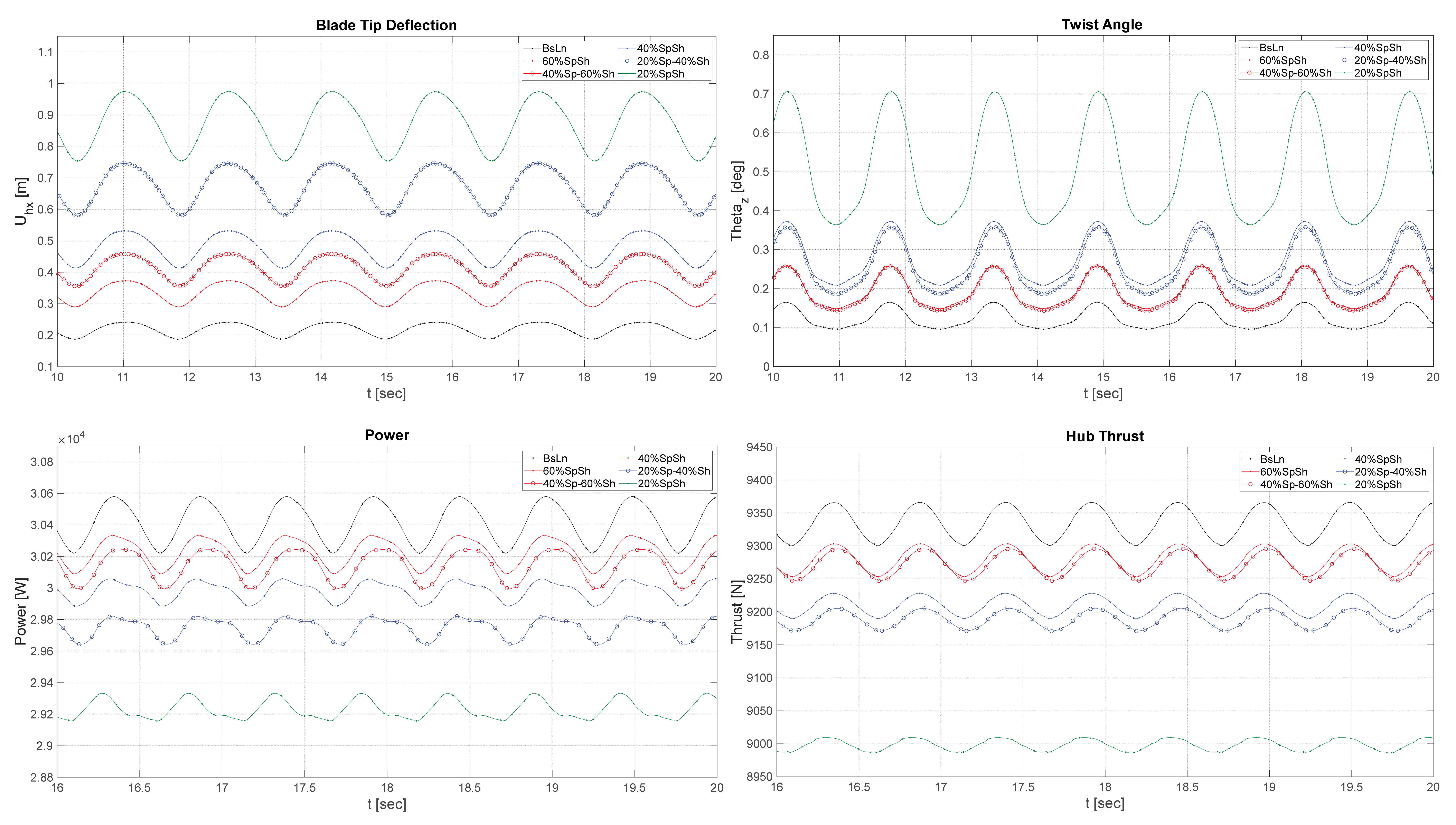
Figure 12.
Time evolution of blade-tip deflection, twist angle at 90% of the blade span, power, and thrust at the hub during typical nighttime conditions, with yaw offset = .
These plots offer a demonstration of each blade variation’s structural response to the operational conditions imposed by the daytime and nighttime atmospheric flow states, in addition to the effects of yaw offset. This information is also used to anticipate the consequences that may occur in the downstream vortex-wake structure and farm flow-field velocity distribution, which is discussed later in Section 3.3.
In order to summarize the effects of the flexibility variations on some essential parameters illustrated in the preceding figures, Table 2 shows the mean values of rotor thrust, torque, and blade-tip deflection (BTD) for the sample of the results shown in Figure 9, together with their corresponding standard deviations. Table 3 shows a summary of the same set of data for the sample of the results shown in Figure 12. These two scenarios are particularly relevant as they constitute the most extreme ends of the spectrum of conditions that impose cyclically varying aerodynamic loads at the rotor.
Table 2.
Summarized data from aeroelastic simulations of the NRT flexible variations operating during the daytime conditions at 6 m/s, shown in Figure 9. Data are averaged over 7 cycles.
Table 3.
Summarized data from aeroelastic simulations of the NRT flexible variations operating during the nighttime conditions at 6 m/s, shown in Figure 12. Data are averaged over 7 cycles.
3.3. Wake Structure and Velocity Patterns Simulated for Flexible Variations of the NRT Blade
Based on the observations in Section 3.2, flexible variations (B), (D), and (E) were determined to exhibit aeroelastic oscillatory behaviors that are likely to evoke the most significant changes to the vortex-wake structure and downstream flow velocity patterns, and were, therefore, chosen to perform a further wake-focused study. To investigate these changes, the selected blade variations were simulated with CODEF-GVLM to evaluate the vortex-wake structure interactions in daytime and nighttime conditions, with and without yaw offset.
The following series of figures present a subset of the results to summarize the findings of the study, specifically including simulations of daytime conditions without yaw, and nighttime conditions with yaw. As discussed earlier in this section, the comparison of these two scenarios is posed to elucidate the behaviors caused by the most extreme ends of the spectrum of conditions that impose cyclically varying aerodynamic loads at the rotor.
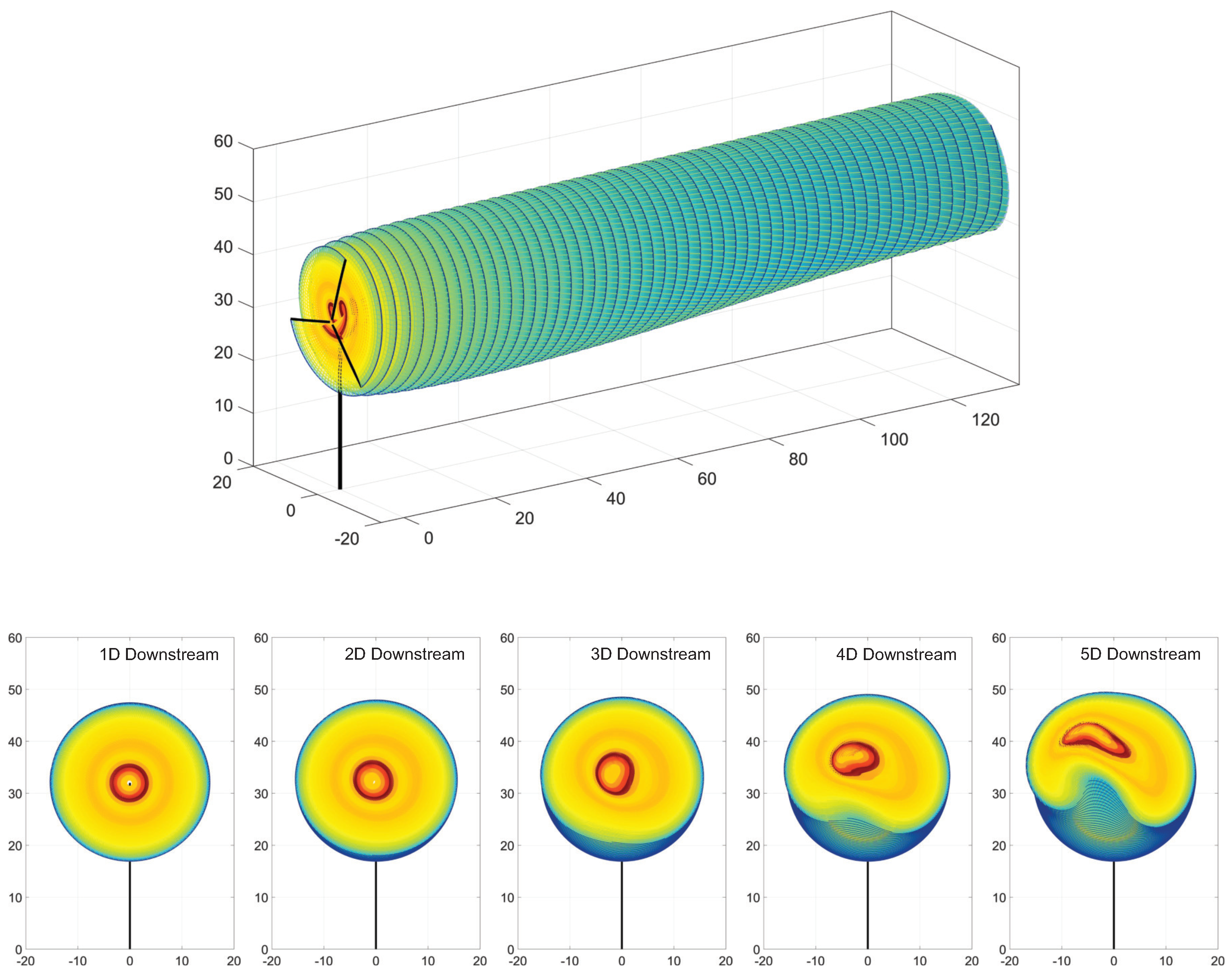
Figure 13 and Figure 14 provide visualizations of the simulated vortex lattice structure for the baseline blade. Conditions include daytime with no yaw, and nighttime with yaw, respectively. Both figures show a perspective view, followed by rear cross-sectional views at distances from one diameter (1D) to five diameters (5D) downstream of the turbine, in increments of one diameter. The color scheme used in all vortex lattice images in this section is intended to provide a better appreciation of the lattice shape development, and is not attached to any specific physical quantity.

Figure 13.
Vortex lattice structures for the NRT baseline rotor, operating in day conditions with yaw offset = . Perspective view, followed by cross-cuts at 1 to 5 diameters downstream of the turbine. The color scheme used is intended to provide a better appreciation of the lattice shape development, and is not attached to a specific physical quantity.

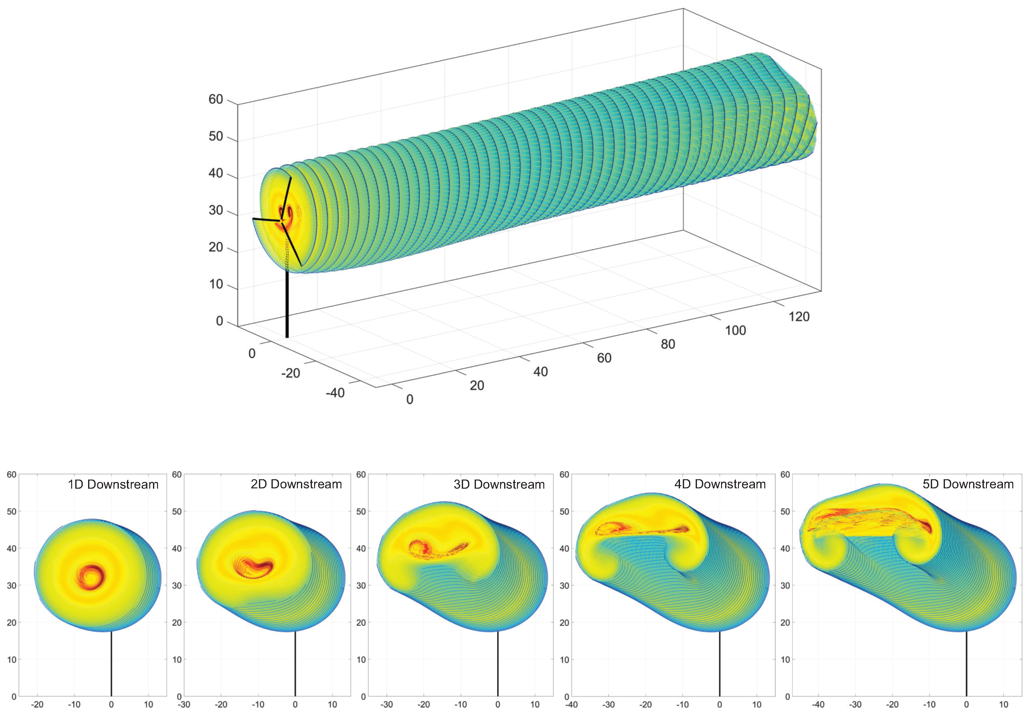
Figure 14.
Vortex lattice structure for the NRT baseline rotor, operating in nighttime conditions with yaw offset = . Perspective view, followed by cross-cuts at 1 to 5 diameters downstream of the turbine. The color scheme used is intended to provide a better appreciation of the lattice shape development, and is not attached to a specific physical quantity.
Observing the wake-structure evolutions in Figure 13 and Figure 14, there are several effects that can be noticed, which occur when the turbine operates in a background wind flow with variable velocity profile. These effects manifest themselves as wake-structure patterns that exhibit substantial differences from the basic cylindrical form that could be observed in a vortex wake evolving in a steady-state, uniform-stream wind flow.
When a wind turbine operates in an atmospheric condition with a nonuniform inflow velocity profile, there are a variety of effects that may emerge in the turbine’s vortex-wake structure, due the dynamic mutual advection of vortex filaments within a changing velocity flow field. These effects substantially distinguish wakes formed in variable background wind scenarios from those which are observed in uniform, steady-state flow that is comparable to what can be found in wind tunnel test conditions.
Rotor operation in a regularized flow state of uniform velocity produces a vortex-wake lattice structure which is extremely orderly, with consistently shed vortex filaments generated from each blade. This forms a spiraling helix of filament-lattices corresponding to the rotation of the blades, where the cylindrical center is associated with the wake core, and filaments representing blade-tip vortices are neatly coiled around it. The wake will gradually lose vorticity strength due turbulent viscous diffusion, but its regularized structure remains preserved in shape as it is advected with a uniform background flow velocity. Thus, the downstream axial flow velocity induced by this typical vortex-filament structure appears as a circular region of velocity deficit, corresponding to the cross-sectional zone circumscribed by the wake.
Wind turbine wakes formed in variable velocity inflow conditions will substantially deviate from this pattern of regularized vortex lattice generation and evolution. Observable effects occur in scenarios where the wind flow profile imposes a cross-flow variation in velocity magnitude or direction, which can be caused by a vertical shear profile, yaw offset, veer, or other conditions. In this type of flow state, the advection speed of a filament becomes dependent on its relative cross-sectional position within the wake, which leads to nonuniform patterns of mutual advection. This introduces fundamental changes to the shape and structure of the vortex wake, as filaments exhibit irregular shifts in their relative position and speed of propagation.
The observable consequences of variable inflow velocity are evident in Figure 13 and Figure 14, where the shear profile introduces a notable effect in the evolution of the vortex-filament structure. In this case, the increase in background wind velocity with height causes filaments located in higher positions to advect faster than those located below, thus affecting the relative arrangement of filaments within the vertical plane of the wake structure. Due to this vertical gradient of mutual advection, the original cylindrical wake structure starts to roll up into a formation resembling a “ram horn” shape appearing in stream-wise cross-sections, and the overall direction of the wake’s propagation is deflected upwards.
These effects are visually exemplified in the progressive cross-sectional views of vortex lattice formations at locations downstream of the turbine. Vortex-wake structure transitions, which are similarly associated with the influence of incident wind velocity changes, are collectively referred to as wake meandering, and are well documented in many research works, including Zong and Porté-Agel [59], Porté-Agel et al. [60], Abkar et al. [61], Su and Bliss [62], Baruah and Ponta [42], and other works.
The GVLM vortex lattice assemblies can be used to calculate the induced velocity patterns in the wake downstream of the turbine. Figure 15 shows the velocity patterns plotted on cross-cut section planes up to seven diameters downstream of the turbine, at intervals of one diameter. These again show the results of the baseline blade operating in daytime conditions without yaw, and nighttime conditions with yaw, respectively.
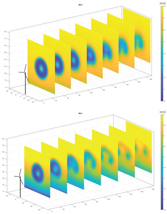
Figure 15.
Perspective views of wake velocity patterns at cross-cut planes from 1D to 7D downstream. Top: daytime conditions, yaw offset = . Bottom: nighttime conditions, yaw offset = .
To frame a direct comparison of the wake effects imposed by flexible blade variations (B), (D), and (E), the downstream velocity patterns were calculated for the selected blade variations and subtracted from the velocity patterns for the baseline blade.
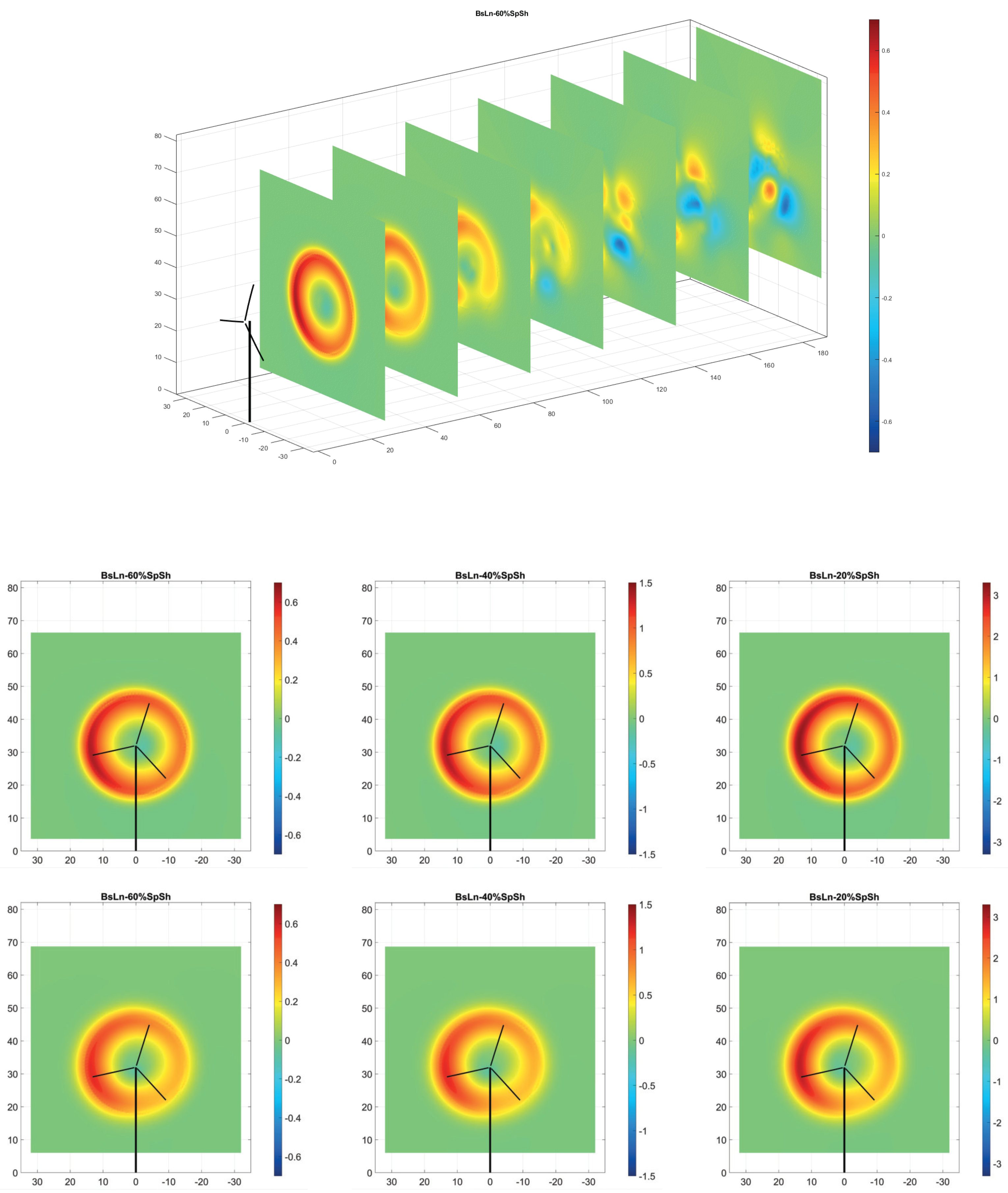
Figure 16 and Figure 17 provide visualizations of the percentage velocity difference, normalized by the magnitude of the incident wind. In these figures, the top plot serves as a perspective view reference, showing the cross-cut sections of velocity difference, plotted at distances up to seven diameters downstream at intervals of one diameter. The matrix of frames then show the individual cut planes for a more detailed analysis of the wake velocity difference patterns. They are arranged to show wake velocity differences for cases (B), (D), and (E) in columns from left to right, with rows corresponding to the number of diameters downstream.
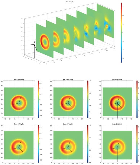
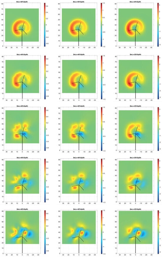
Figure 16.
Visualizations of the normalized wake velocity difference percentage between the the NRT baseline blade and its three flexible variations during daytime conditions with yaw offset = 0°, plotted on cross-section cut planes from 1D to 7D downstream. Top shows a perspective view of the cross-section cut planes positioned for reference, and the following plots include the individual cross-cut planes. In the series of frames shown, the three columns correspond to each case (BsLn-60%, BsLn-40%, and BsLn-20%, respectively), and the seven rows correspond to the distance downstream from the turbine (from 1D to 7D, respectively).
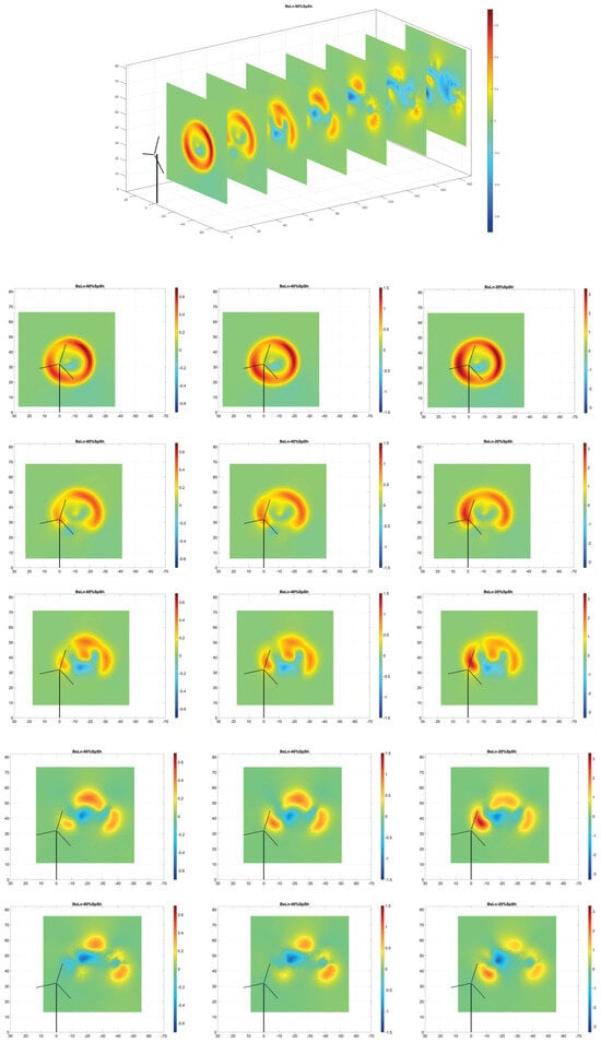
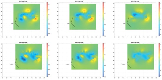
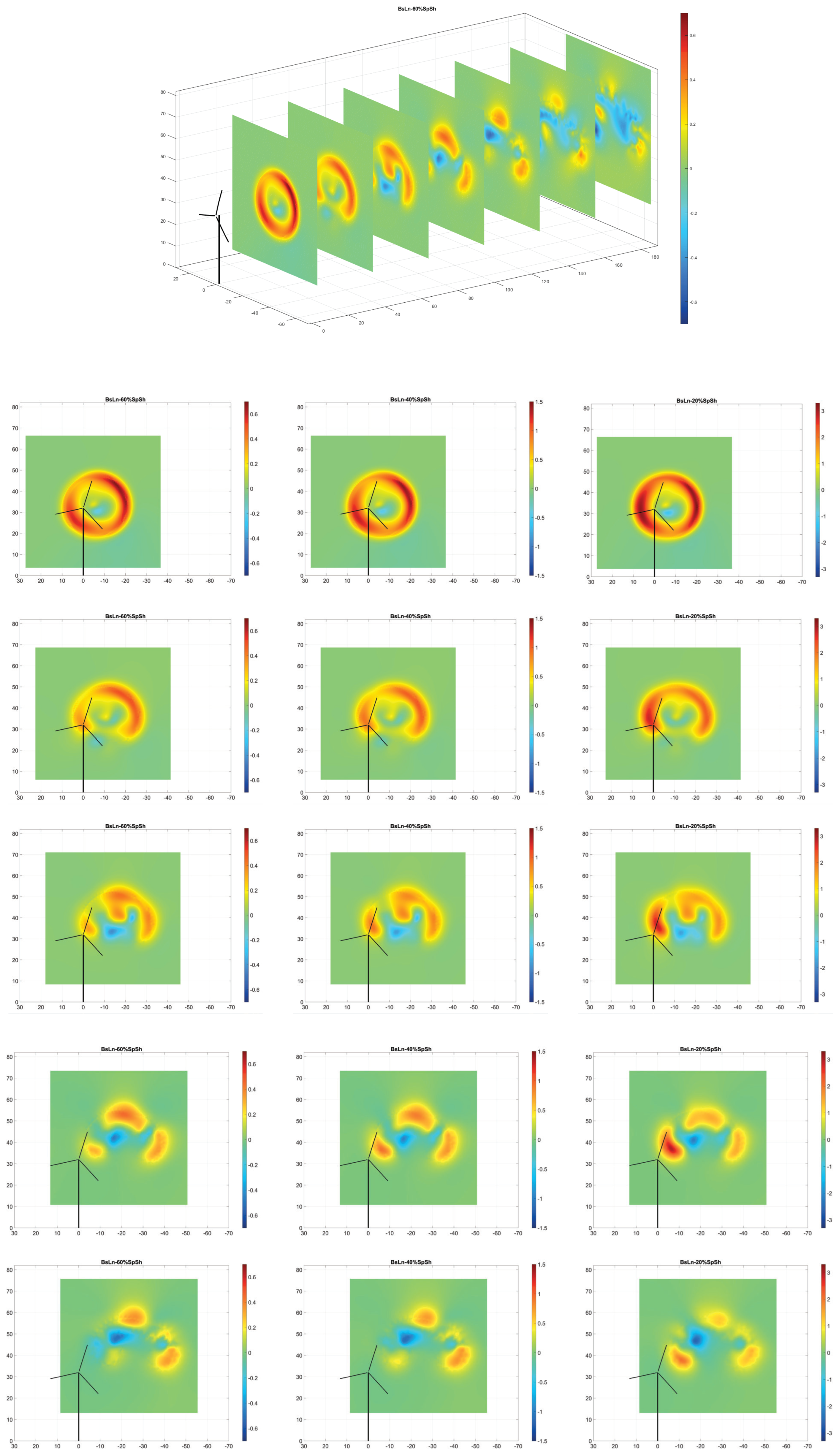
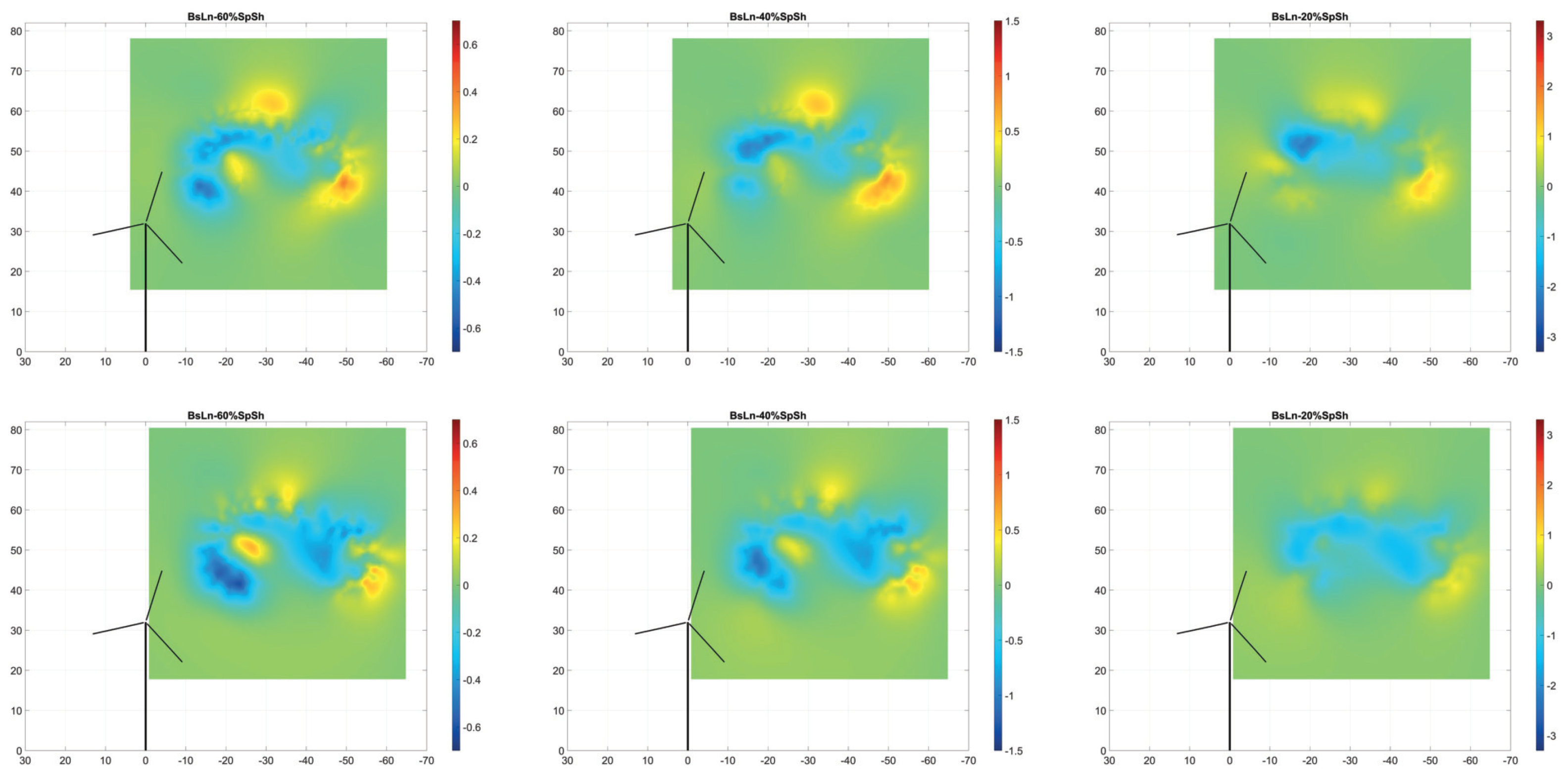
Figure 17.
Visualizations of the normalized wake velocity difference percentage between the the NRT baseline blade and its three flexible variations during nighttime conditions with yaw offset = , on cross-section cut planes from 1D to 7D downstream. Top shows a perspective view of the cross-section cut planes positioned for reference, and the following plots include the individual cross-cut planes. In the series of frames shown, the three columns correspond to each case (BsLn-60%, BsLn-40%, and BsLn-20%, respectively), and the seven rows correspond to the distance downstream from the turbine (from 1D to 7D, respectively).
4. Conclusions
A first series of flexible variations was designed based on the constructive characteristics of the SNL-NRT baseline blade, including airfoil shapes, span-wise distribution of geometrical and structural properties, internal structure layout, and materials. By altering the material distribution and scaling the thicknesses of different components of the blade’s internal structure by a factor of 80%, alternative ways of softening the blade were explored.
Simulations were conducted for the aeroelastic oscillatory response of these 80% flexible variations, and the time evolution of several variables that illustrate the structural response when exposed to the daytime and nighttime flow patterns were examined in comparison with the baseline blade. In particular, the blade-tip deflection, torsional angle, angle of attack, and aerodynamic loads at some representative blade sections, and power, torque, and thrust at the hub were reviewed.
From those results, the thicknesses of the spar cap and the shell were identified as the most important factors in terms of controlling the blade’s different modes of deformation. A strong shell contribution to the overall stiffness of the NRT blade was found, emphasized by an addition of unifilar material to the bilinear layers of the shell structure, located in the region of the span between 7% and 20% from the root. At its peak, around the 11% and 13% stations, these layers of unifilar material were quite substantial in proportion to the total of unifilar spar-cap material thickness. Thus, in the variations created, cases were added where that portion of shell unifiliar material was also reduced together with the spar cap. Combinations of thickness reductions in the shell as a whole were also tried, as well as thickness reductions in the shell plus the spar cap.
Based on the previous results, a second series of structural modifications was explored, where five new blade variations of increased flexibility were created by combining different scaling factors for the spar cap and the shell thicknesses. Their aeroelastic response was analyzed in four different wind scenarios: daytime and nighttime, with and without yaw. Vortex lattice structures and wake velocity patterns for the three variations showing the most significant changes in aeroelastic response were also analyzed. Patterns were plotted at different locations up to seven rotor diameters downstream of the turbine, for two wind scenarios: daytime no-yaw, and nighttime with yaw. These represent the ends of the spectrum in terms of the cyclical variations that they induce in the aerodynamic loads. The differences in wake axial velocity between the baseline blade and each one of those three flexible variations were reported, normalized by the value of the incident wind. They showed maximum percentage variations between 1% and 3.5%, with various distributions in the locus of the pattern of velocity difference.
In terms of how the outcome of this paper might affect the future of blade design, the consequences of blade-weight reduction on the blade deformation and rotor load parameters that could be observed in the summaries of the mean and standard deviation values listed in Table 2 and Table 3, and the curves in the associated Figure 9, Figure 10, Figure 11 and Figure 12, are relatively moderate. Even for the lightest blade variation, 20%SpSh, operating in the most intense nighttime scenario, the increase in tip deflection values, both mean and cyclical fluctuation, are not prohibitively large compared with the original values computed for the baseline blade; and the same could be said about the rotor thrust and torque loads. This aspect is worth noticing, as the advantages of blade-weight reduction in terms of cost reduction of wind energy generation are numerous. Reductions in the cost of materials, labor, and production times in blade manufacturing are clearly evident. But other ancillary aspects could also be included in the cost–benefit equation, like the logistics of blade transport and rotor assembly, and the possibility of overcoming limitations in maximum crane capacity, especially for the much larger blades of the next generation of “super turbines”.
As an outlook for further work, it was observed that, in the steady-in-the-average (SITA) wind conditions cases analyzed during this research, the stimuli of the aerodynamic load fluctuations came from the cyclical motion of the blades traversing through a variable flow field caused by wind shear, tilt, and yaw. In these SITA cases, the frequency of fluctuations was mostly dominated by the rotor’s turning speed, which is comparatively slow versus other stimuli. It could be hypothesized that differences in dynamic response between the baseline blade and its more flexible variations would likely become more intense when rapid temporal fluctuations, based on anemometry data, were added to the input wind. This would be due to the fact that the different natural frequencies in the aeroelastic response of the blade’s flex variations will be triggered by the short-term pulses in the wind signal, impacting the wake structure more intensely. This would substantially affect the vortex-shedding process, altering the wake patterns of each of the different blade types. This aspect will certainly be worth testing as part of a next phase of our research.
Author Contributions
Conceptualization, A.F., A.B. and F.P.; methodology, A.F., A.B. and F.P.; software, A.F., A.B. and F.P.; validation, A.F., A.B. and F.P.; formal analysis, A.B., A.F. and F.P.; investigation, A.B., A.F. and F.P.; resources, A.F., A.B. and F.P.; data curation, A.F., A.B. and F.P.; writing—original draft preparation, A.F., A.B. and F.P.; writing—review and editing, A.F., A.B. and F.P.; visualization, A.F., A.B. and F.P.; supervision, F.P.; project administration, F.P.; funding acquisition, F.P. All authors have read and agreed to the published version of the manuscript.
Funding
The authors gratefully acknowledge the financial support of Sandia National Laboratories, USA, through awards PO-2074866 and PO-2159403, and the ME-EM Department at Michigan Technological University.
Data Availability Statement
The original contributions presented in the study are included in the article, further inquiries can be directed to the corresponding authors.
Conflicts of Interest
The authors declare no conflicts of interest.
References
- IRENA. Global Energy Transformation: A Roadmap to 2050; Technical Report; International Renewable Energy Agency: Abu Dhabi, United Arab Emirates, 2019. [Google Scholar]
- Dykes, K.L.; Veers, P.S.; Lantz, E.J.; Holttinen, H.; Carlson, O.; Tuohy, A.; Sempreviva, A.M.; Clifton, A.; Rodrigo, J.S.; Berry, D.S.; et al. IEA Wind TCP: Results of IEA Wind TCP Workshop on a Grand Vision for Wind Energy Technology; Technical Report NREL/TP-5000-72437; National Renewable Energy Laboratory: Golden, CO, USA, 2019.
- TPI Composites Inc. Parametric Study for Large Wind Turbine Blades; Report SAND2002-2519; Sandia National Laboratories: Albuquerque, NM, USA, 2002.
- Griffin, D.A. Blade System Design Studies Volume I: Composite Technologies for Large Wind Turbine Blades; Report SAND2002-1879; Sandia National Laboratories: Albuquerque, NM, USA, 2002.
- Veers, P.; Dykes, K.; Basu, S.; Bianchini, A.; Clifton, A.; Green, P.; Holttinen, H.; Kitzing, L.; Kosovic, B.; Lundquist, J.K.; et al. Grand Challenges: Wind energy research needs for a global energy transition. Wind. Energy Sci. 2022, 7, 2491–2496. [Google Scholar] [CrossRef]
- Stiesdal, H. Rotor loadings on the Bonus 450 kW turbine. J. Wind Eng. Ind. Aerodyn. 1992, 39, 303–315. [Google Scholar] [CrossRef]
- Kong, C.; Bang, J.; Sugiyama, Y. Structural investigation of composite wind turbine blade considering various load cases and fatigue life. Energy 2005, 30, 2101–2114. [Google Scholar] [CrossRef]
- Loth, E.; Fingersh, L.; Griffith, D.; Kaminski, M.; Qin, C. Gravo-aeroelastically scaling for extreme-scale wind turbines. In Proceedings of the 35th AIAA Applied Aerodynamics Conference, Denver, CO, USA, 5–9 June 2017. [Google Scholar]
- Otero, A.D.; Ponta, F.L.; Lago, L.I. Structural Analysis of Complex Wind Turbine Blades: Flexo-Torsional Vibrational Modes. In Advances in Wind Power; Carriveau, R., Ed.; InTech: London, UK, 2012; pp. 123–149. [Google Scholar]
- Tabor, A. Testing on the Ground Before You Fly: Wind Tunnels at NASA Ames. 2020. Available online: https://www.nasa.gov/centers-and-facilities/ames/testing-on-the-ground-before-you-fly-wind-tunnels-at-nasa-ames/ (accessed on 10 January 2024).
- Gebraad, P.M.; Teeuwisse, F.W.; Van Wingerden, J.; Fleming, P.A.; Ruben, S.D.; Marden, J.R.; Pao, L.Y. Wind plant power optimization through yaw control using a parametric model for wake effects—A CFD simulation study. Wind Energy 2016, 19, 95–114. [Google Scholar] [CrossRef]
- Van Bussel, G.J. The Aerodynamics of Horizontal Axis Wind Turbine Rotors Explored with Asymptotic Expansion Methods. Ph.D. Thesis, Delft University of Technology, Delft, The Netherlands, 1995. [Google Scholar]
- Hansen, M.; Sorensen, J.; Michelsen, J.; Sorensen, N.; Hansen, M.; Sorensen, J.; Michelsen, J.; Sorensen, N. A global Navier-Stokes rotor prediction model. In Proceedings of the 35th Aerospace Sciences Meeting and Exhibit, Reno, NV, USA, 6–9 January 1997; p. 970. [Google Scholar]
- Maronga, B.; Gryschka, M.; Heinze, R.; Hoffmann, F.; Kanani-Sühring, F.; Keck, M.; Ketelsen, K.; Letzel, M.O.; Sühring, M.; Raasch, S. The Parallelized Large-Eddy Simulation Model (PALM) version 4.0 for atmospheric and oceanic flows: Model formulation, recent developments, and future perspectives. Geosci. Model Dev. 2015, 8, 2515–2551. [Google Scholar] [CrossRef]
- Churchfield, M.; Lee, S.; Moriarty, P.; Martinez, L.; Leonardi, S.; Vijayakumar, G.; Brasseur, J. A large-eddy simulation of wind-plant aerodynamics. In Proceedings of the 50th AIAA Aerospace Sciences Meeting including the New Horizons Forum and Aerospace Exposition, Nashville, TN, USA, 9–12 January 2012; p. 537. [Google Scholar]
- Domino, S. Sierra Low Mach Module: Nalu Theory Manual 1.0; Sandia National Laboratories: Albuquerque, NM, USA, 2015.
- Ekaterinaris, J.A. Numerical simulation of incompressible two-blade rotor flowfields. J. Propuls. Power 1998, 14, 367–374. [Google Scholar] [CrossRef]
- Duque, E.; Van Dam, C.; Hughes, S. Navier-Stokes simulations of the NREL combined experiment phase II rotor. In Proceedings of the 37th Aerospace Sciences Meeting and Exhibit, Reno, NV, USA, 11–14 January 1999; p. 37. [Google Scholar]
- Sorensen, N. Aerodynamic predictions for the unsteady aerodynamics experiment phase-II rotor at the National Renewable Energy Laboratory. In Proceedings of the 2000 ASME Wind Energy Symposium, Reno, NV, USA, 10–13 January 2000; p. 37. [Google Scholar]
- Sprague, M.A.; Geers, T.L. Legendre spectral finite elements for structural dynamics analysis. Commun. Numer. Methods Eng. 2007, 24, 1953–1965. [Google Scholar] [CrossRef]
- Doubrawa, P.; Quon, E.W.; Martinez-Tossas, L.A.; Shaler, K.; Debnath, M.; Hamilton, N.; Herges, T.G.; Maniaci, D.; Kelley, C.L.; Hsieh, A.S.; et al. Multimodel validation of single wakes in neutral and stratified atmospheric conditions. Wind Energy 2020, 23, 2027–2055. [Google Scholar] [CrossRef]
- Lignarolo, L.E.; Mehta, D.; Stevens, R.J.; Yilmaz, A.E.; van Kuik, G.; Andersen, S.J.; Meneveau, C.; Ferreira, C.J.; Ragni, D.; Meyers, J.; et al. Validation of four LES and a vortex model against stereo-PIV measurements in the near wake of an actuator disc and a wind turbine. Renew. Energy 2016, 94, 510–523. [Google Scholar] [CrossRef]
- Burton, T.; Sharpe, D.; Jenkins, N.; Bossanyi, E. Wind Energy Handbook; Wiley: Chichester, UK, 2001. [Google Scholar]
- Manwell, J.F.; McGowan, J.G.; Rogers, A.L. Wind Energy Explained: Theory, Design and Application; Wiley: Chichester, UK, 2009. [Google Scholar]
- Ponta, F.L.; Otero, A.D.; Lago, L.I.; Rajan, A. Effects of rotor deformation in wind-turbine performance: The Dynamic Rotor Deformation Blade Element Momentum model (DRD–BEM). Renew. Energy 2016, 92, 157–170. [Google Scholar] [CrossRef]
- Kelley, C.L. Aerodynamic Design of the National Rotor Testbed; Technical Report SAND2015-8989; Sandia National Laboratory: Albuquerque, NM, USA, 2015.
- Kelley, C.L.; Ennis, B.L. SWiFT Site Atmospheric Characterization; Technical Report SAND2016-0216; Sandia National Laboratory: Albuquerque, NM, USA, 2016.
- Berg, J.; Bryant, J.; LeBlanc, B.; Maniaci, D.C.; Naughton, B.; Paquette, J.A.; Resor, B.R.; White, J.; Kroeker, D. Scaled wind farm technology facility overview. In Proceedings of the 32nd ASME Wind Energy Symposium, National Harbor, MD, USA, 13–17 January 2014; p. 1088. [Google Scholar]
- Barone, M.F.; White, J. DOE/SNL-TTU Scaled Wind Farm Technology Facility; Technical Report SAND2011-6522; Sandia National Laboratory: Albuquerque, NM, USA, 2011.
- Jonkman, J.; Butterfield, S.; Musial, W.; Scott, G. Definition of a 5-MW Reference Wind Turbine for Offshore System Development; Technical Report NREL/TP-500-38060; National Renewable Energy Laboratory: Golden, CO, USA, 2009.
- Xudong, W.; Shen, W.Z.; Zhu, W.J.; Sorensen, J.; Jin, C. Shape optimization of wind turbine blades. Wind Energy 2009, 12, 781–803. [Google Scholar] [CrossRef]
- Menon, M.; Ponta, F. Dynamic Aeroelastic Behavior of Wind Turbine Rotors in Rapid Pitch-Control Actions. Renew. Energy 2017, 107, 327–339. [Google Scholar] [CrossRef]
- Menon, M.; Ponta, F. Aeroelastic Response of Wind Turbine Rotors under Rapid Actuation of Flap-Based Flow Control Devices. Fluids 2022, 7, 129. [Google Scholar] [CrossRef]
- Otero, A.D.; Ponta, F.L. On the sources of cyclic loads in horizontal-axis wind turbines: The role of blade-section misalignment. Renew. Energy 2018, 117, 275–286. [Google Scholar] [CrossRef]
- Jalal, S.; Ponta, F.; Baruah, A.; Rajan, A. Dynamic Aeroelastic Response of Stall-Controlled Wind Turbine Rotors in Turbulent Wind Conditions. Appl. Sci. 2021, 11, 6886. [Google Scholar] [CrossRef]
- Jalal, S.; Ponta, F.; Baruah, A. Aeroelastic Response of Variable-Speed Stall-Controlled Wind Turbine Rotors. In Proceedings of the ASME 2019 13th International Conference on Energy Sustainability, Bellevue, WA, USA, 14–17 July 2019; American Society of Mechanical Engineers: New York, NY, USA, 2019; p. ES2019-3803. [Google Scholar]
- Lago, L.I.; Ponta, F.L.; Otero, A.D. Analysis of alternative adaptive geometrical configurations for the NREL-5 MW wind turbine blade. Renew. Energy 2013, 59, 13–22. [Google Scholar] [CrossRef]
- Rajan, A.; Ponta, F.L. A Novel Correlation Model for Horizontal Axis Wind Turbines Operating at High-Interference Flow Regimes. Energies 2019, 12, 1148. [Google Scholar] [CrossRef]
- Hodges, D.H. Nonlinear Composite Beam Theory; AIAA: Reston, VA, USA, 2006. [Google Scholar]
- Yu, W.; Hodges, D.H.; Volovoi, V.; Cesnik, C.E.S. On Timoshenko-like modeling of initially curved and twisted composite beams. Int. J. Sol. Struct. 2002, 39, 5101–5121. [Google Scholar] [CrossRef]
- Otero, A.D.; Ponta, F.L. Structural Analysis of Wind-Turbine Blades by a Generalized Timoshenko Beam Model. J. Sol. Energy Eng. 2010, 132, 011015. [Google Scholar] [CrossRef]
- Baruah, A.; Ponta, F. Analysis of Wind Turbine Wake Dynamics by a Gaussian-Core Vortex Lattice Technique. Dynamics 2024, 4, 97–118. [Google Scholar] [CrossRef]
- Herges, T.; Maniaci, D.C.; Naughton, B.T.; Mikkelsen, T.; Sjöholm, M. High resolution wind turbine wake measurements with a scanning lidar. J. Phys. Conf. Ser. 2017, 854, 012021. [Google Scholar] [CrossRef]
- Batchelor, G.K. An Introduction to Fluid Dynamics; Cambridge University Press: Cambridge, UK, 2000. [Google Scholar]
- Ponta, F.L.; Jacovkis, P.M. A vortex model for Darrieus turbine using finite element techniques. Renew. Energy 2001, 24, 1–18. [Google Scholar] [CrossRef]
- Strickland, J.H.; Webster, B.T.; Nguyen, T. A Vortex Model of the Darrieus Turbine: An Analytical and Experimental Study. J. Fluids Eng. 1979, 101, 500–505. [Google Scholar] [CrossRef]
- Ponta, F.L. Vortex decay in the Kármán eddy street. Phys. Fluids 2010, 22, 093601. [Google Scholar] [CrossRef]
- Trieling, R.R.; van Wesenbeeck, J.M.A.; van Heijst, G.J.F. Dipolar vortices in a strain flow. Phys. Fluids 1998, 10, 144–159. [Google Scholar] [CrossRef]
- Flór, J.B.; van Heijst, G.J.F. An experimental study of dipolar structures in a stratified fluid. J. Fluid Mech. 1994, 279, 101–133. [Google Scholar] [CrossRef]
- Lamb, H. Hydrodynamics, 6th ed.; Cambridge University Press: Cambridge, UK, 1932. [Google Scholar]
- Hooker, S.G. On the action of viscosity in increasing the spacing ration of a vortex street. Proc. R. Soc. 1936, A154, 67–89. [Google Scholar]
- Karamcheti, K. Principles of Ideal-Fluid Aerodynamics; Wiley: New York, NY, USA, 1966. [Google Scholar]
- Cottet, G.H.; Koumoutsakos, P.D. Vortex Methods: Theory and Practice; Cambridge University Press: London, UK, 2000. [Google Scholar]
- Kelley, C.; Naughton, B. Surface Meteorological Station-SWiFT Southwest-METa1-Reviewed Data. 2021. Available online: https://www.osti.gov/biblio/1349888 (accessed on 20 December 2023).
- Trudnowski, D.; LeMieux, D. Independent pitch control using rotor position feedback for wind-shear and gravity fatigue reduction in a wind turbine. In Proceedings of the 2002 American Control Conference (IEEE Cat. No. CH37301), Anchorage, AK, USA, 8–10 May 2002; Volume 6, pp. 4335–4340. [Google Scholar]
- EWEA. Upwind: Design Limits and Solutions for Very Large Wind Turbines; Sixth Framework Programme; European Wind Energy Association: Brussels, Belgium, 2011. [Google Scholar]
- Hohenemser, K.H.; Swift, A.; Peters, D. Yawing of Wind Turbines with Blade Cyclic Pitch Variation; Technical Report; Solar Energy Research Institute: Golden, CO, USA; Washington University Technology Associates, Inc.: St. Louis, MO, USA, 1981. [Google Scholar]
- Jonkman, J.M.; Buhl, M.L., Jr. FAST User’s Guide; Technical Report NREL/EL-500-38230; National Renewable Energy Laboratory (NREL): Golden, CO, USA, 2005.
- Zong, H.; Porté-Agel, F. Experimental investigation and analytical modelling of active yaw control for wind farm power optimization. Renew. Energy 2021, 170, 1228–1244. [Google Scholar] [CrossRef]
- Porté-Agel, F.; Bastankhah, M.; Shamsoddin, S. Wind-Turbine and Wind-Farm Flows: A Review. Bound.-Layer Meteorol. 2020, 174, 1–59. [Google Scholar] [CrossRef]
- Abkar, M.; Sørensen, J.N.; Porté-Agel, F. An Analytical Model for the Effect of Vertical Wind Veer on Wind Turbine Wakes. Energies 2018, 11, 1838. [Google Scholar] [CrossRef]
- Su, K.; Bliss, D. A numerical study of tilt-based wake steering using a hybrid free-wake method. Wind Energy 2020, 23, 258–273. [Google Scholar] [CrossRef]


Disclaimer/Publisher’s Note: The statements, opinions and data contained in all publications are solely those of the individual author(s) and contributor(s) and not of MDPI and/or the editor(s). MDPI and/or the editor(s) disclaim responsibility for any injury to people or property resulting from any ideas, methods, instructions or products referred to in the content. |
© 2024 by the authors. Licensee MDPI, Basel, Switzerland. This article is an open access article distributed under the terms and conditions of the Creative Commons Attribution (CC BY) license (https://creativecommons.org/licenses/by/4.0/).