
Transceiver Optimization for Multiuser Multiple-Input Multiple-Output Full-Duplex Amplify-and-Forward Relay Downlink Communications


Department of Electrical and Computer Engineering, University of Victoria, Victoria, BC V8W 2Y2, Canada
*
Author to whom correspondence should be addressed.
†
Current address: Department of Computer Science, New York Institute of Technology Vancouver, Vancouver, BC V5M 4X3, Canada.
‡
These authors contributed equally to this work.
Telecom 2024, 5(1), 216-227; https://doi.org/10.3390/telecom5010011
Submission received: 26 December 2023
/
Revised: 23 February 2024
/
Accepted: 1 March 2024
/
Published: 6 March 2024
(This article belongs to the Special Issue Advances in Wireless Communication: Applications and Developments)
Abstract
:This paper considers the transceiver design in a multiuser multiple-input multiple-output (MIMO) full-duplex (FD) amplify-and-forward (AF) relay downlink communication system, where users simultaneously transmit data via an FD relay node. The design incorporates an imperfect loop interference (LI) cancellation which results in a residual LI. Linear precoders are employed at the sources and relay, and minimum mean-squared-error (MMSE) combiners are employed at the destinations to mitigate the effect of the residual LI. The corresponding design problem is highly nonconvex, so a closed-form solution is intractable. Thus, an iterative method is developed to solve this optimization problem. Simulation results are presented which show that the proposed iterative algorithm provides better performance than the corresponding half-duplex (HD) solution in terms of the achievable rate under residual LI.
1. Introduction
Multiple-input multiple-output (MIMO) relay communication systems have been the subject of considerable research due to their ability to improve both achievable rates and coverage [1,2,3,4,5,6]. A relay is used between the source and destination, so the signal is transmitted from the source to the relay and then from the relay to the destination. The relay node can employ either the decode-and-forward (DF) or amplify-and-forward (AF) protocols. AF amplifies the received signal and forwards it to the destination, so it has a lower complexity than the DF protocol [7].
Precoding is a well-known technique for interference mitigation. A joint precoding optimization for a multiuser relay downlink system was investigated in [1]. The sum capacity was maximized by using quadratic programming, but multiple antennas were employed only at the relay. The performance can be improved by using multiple antennas at the source and destination. A transceiver design for a multiuser non-regenerative MIMO relay system with multiple antennas at both the source and destination was investigated in [2,3,4,5,6]. However, a half-duplex (HD) relay was employed, so transmission from the source to destination requires an extra time slot which limits the potential capacity.
In the past decade, full-duplex (FD) relay systems have attracted attention because data transmission from a source to a destination can be completed in one time slot [7,8,9,10,11]. Thus, FD MIMO relaying can increase capacity compared to HD systems [9], but loop interference (LI) is a critical issue because the relay transmits and receives simultaneously. In general, the LI is much larger than the channel noise and so can significantly degrade performance. As a consequence, several LI cancellation techniques have been developed [10]. Temporal cancellation methods such as antenna isolation and analog/digital precancellation have been shown to be effective. However, it is impossible to cancel the LI completely, and the residual LI can still be larger than the noise [12].
Estimating channel state information (CSI) is challenging due to the dynamic nature of wireless environments and the complexity of modern communication systems. However, current estimation algorithms have been shown to provide good accuracy, particularly in cellular systems [13]. Thus, it can be assumed that CSI is available in the proposed system. In [14], deep neural networks were considered for channel estimation with multiuser precoding in the downlink of a frequency-division duplex massive MIMO system. In [15], an efficient transceiver design was examined for full-duplex (FD) multiuser massive MIMO systems operating in millimeter wave frequencies. An iterative solution was developed for the proposed digital MMSE transceiver beamforming. Secrecy in cell-free massive MIMO systems was proposed in [16] through the joint optimization of uplink power control, downlink beamforming, and duplex mode selection. Artificial noise was incorporated, and an iterative method was used to solve the associated nonconcave–convex approximation. In [17], beamforming was investigated for in-band FD multi-cell multiuser MIMO networks. Hardware impairments, channel uncertainty, and limited channel state information (CSI) were considered in the MMSE beamforming design to improve system performance under global and local CSI. However, none of the approaches in the literature considered the practical limitation of residual loop interference due to imperfect CSI cancellation. This interference should be considered in developing robust and effective wireless communication systems. The impact of residual self-interference (SI) and loop interference (LI) in a full-duplex space shift keying communication system was investigated in [18]. Thus, the residual LI due to imperfect interference cancellation is considered in this paper.
Unlike the uplink communications in [19], this paper considers a MIMO FD relaying downlink communication system with multiple source–destination pairs. A transceiver design for the sources and relay, and a linear combiner design at the destinations, are investigated considering the residual LI with the goal of minimizing the MSE of the received signals at the destinations. An iterative algorithm is developed to update the source and relay transceiver matrices and the linear combining matrix at the destinations.
The remainder of this paper is organized as follows. Section 2 presents the system model, and the optimization problem is solved in Section 3. Results are presented in Section 4, which demonstrate the effectiveness of this solution, and some conclusions are given in Section 5.
Notation: Bold uppercase, bold lowercase, and normal letters denote matrices, vectors, and scalars, respectively. denotes matrix vectorization, ⊗ denotes the matrix Kronecker product, is the trace of a matrix, and is the identity matrix.
2. System Model
Consider a MIMO full-duplex (FD) relay system with K source–destination pairs communicating simultaneously with the aid of a relay. The source-to-destination links are assumed to be inconsequential due to the large-scale fading and the large distances between them.
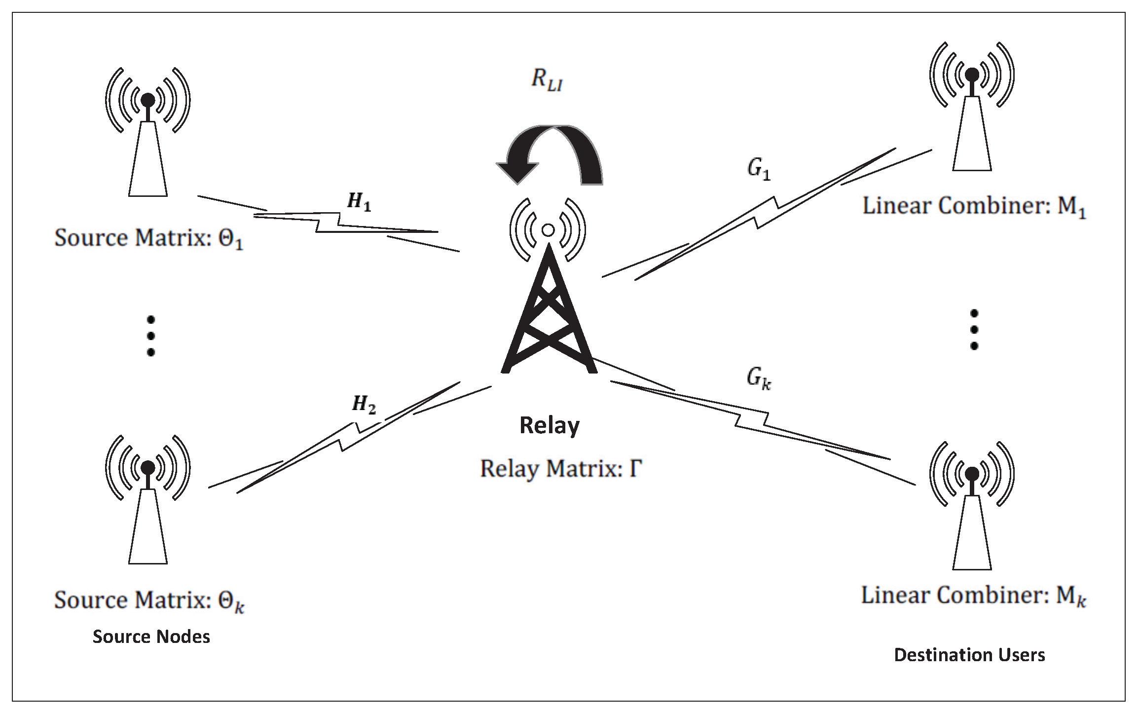
Figure 1 presents the system model with the kth source–destination pairs equipped with and antennas, respectively. The FD relay has and antennas to simultaneously receive and transmit signals, respectively. Therefore, communication between the source–destination pairs is accomplished in one time slot compared to an HD system that requires two time slots.
Let represent the length d signal vector at time n for the kth source. A linear transceiver matrix is applied to before transmission. The received signal at the relay can then be expressed as
where is the channel between source k and the relay node, is the loop interference (LI) channels, and is an independent and identically distributed (i.i.d.) additive white Gaussian noise (AWGN) matrix. As the received signal is corrupted by residual LI, from [12], it can be written as
where , and is the residual LI. At time , the relay amplifies the received signal with a relay transceiver matrix and forwards the resulting signal to the destinations. The received signal at the kth destination is then
where is the channel matrix between the relay and destination k, and is an i.i.d. AWGN vector with a zero mean and unit variance. As in [6,7,12], channel state information (CSI) is assumed to be available at all nodes. In addition, channel variations during the transceiver matrix update interval are assumed to be relatively small [19] and so do not influence the transceiver design [12]. Thus, the received signal at the kth destination can be expressed as
where
As in [18,20], is modeled as white Gaussian noise which is independent of and , and has variance . Consequently, the covariance matrix of is
A linear combiner is used at the kth destination to obtain the signal estimate
The mean square error (MSE) at the kth user is defined as
where and . Optimization is employed to obtain the linear transceiver matrices and at the source and relay, and to obtain the linear combiners at the destinations. The minimization of the sum mean squared error (SMSE) of the received signals at the destinations can be expressed as
where , and and are the power constraints at the kth source and relay, respectively.
3. Optimization Problem Solution
The problem in (9) is highly nonconvex which makes obtaining a global optimal solution intractable, so an iterative algorithm is presented. This solution is based on an alternating optimization that updates , and individually with the other parameters kept fixed to solve the three convex subproblems.
First, given and , the optimal combiner at the kth destination is obtained by solving the unconstrained convex problem for , which is independent of the constraints in (9b) and (9c). The optimal solution can then be obtained by taking the derivative of (8) with respect to and setting it to zero. Solving gives
where
which is known as the Wiener filter.
Second, with from (10) and given , can be obtained by solving the following problem. The objective function in (9) can be expressed as
Note that since is known, the constraint in (9c) is eliminated. The optimization problem then becomes
Consider the singular-value decomposition (SVD) of the equivalent source-to-relay and relay-to-destination channels:
and
The optimal relay precoding matrix is similar to that in [7]:
and from (13) and (14), we have
and
Note that
and
which have dimensions and , respectively. Substituting (13)–(15) in (11) gives
Using the matrix identities
where concatenates the columns of a matrix into a single vector, the SMSE in (11) can be expressed as a function of :
where
does not depend on and
The relay transmit power constraint in (12) can be written as
Defining , (24) can be written as
The original relay optimization problem is then given by
This is a quadratically constrained quadratic programming (QCQP) problem which is convex and so can be efficiently solved using the interior point method. For example, the CVX toolbox for disciplined convex programming [21] can be employed.
Third, the kth source precoding matrix can be obtained using and given above. The corresponding optimization problem can be formulated as the following QCQP problem:
where and can be ignored in the optimization as they do not depend on . Using the matrix identities, (27) can be written as a function of which gives
where
and
which is independent of and so can be ignored. Introducing , where denotes a block-diagonal matrix, and , where and , (27) can be written as a function of , which gives
Now, defining
and
where and , the optimal can be obtained by solving the following problem
This is a QCQP problem which can be solved using the CVX toolbox for disciplined convex programming.
The symbols employed in this work are summarized in Table 1. The proposed iterative algorithm is given in Algorithm 1. The convergence of this algorithm is guaranteed as follows. As the three subproblems are convex, each update of , , and may decrease or at least not increase the value of the objective function. Thus, the iterative algorithm will converge to an optimum solution.
| Algorithm 1: Iterative Design of , , and . |
4. Numerical Results
This section presents the evaluation of the performance of the proposed multiuser MIMO FD relay downlink algorithm using numerical simulation. The CVX toolbox was employed, which is a Matlab-based software package for solving convex optimization problems [21]. For simplicity, we considered a system with two sources and two destinations. The extension to more than two source–destination pairs is straightforward. We assumed that the sources and destinations were each equipped with two antennas, and the relay was equipped with four receive antennas and four transmit antennas. The simulation parameters are given in Table 2.
As in the related literature, flat-fading MIMO channels were considered. It was assumed that the elements of , , and were i.i.d. complex Gaussian random variables with a zero mean and unit variance. Moreover, all noise terms were i.i.d. complex, circularly symmetric Gaussian random variables with a zero mean and unit variance. According to [9], the residual LI can be 0 dB to 20 dB larger than the channel noise. Therefore, LI levels of 0 dB, 5 dB and 10 dB were employed here. In all cases, the results are given for an average of 1000 independent channel realizations. Note that the HD system mentioned in this paper is the same as the proposed FD system except that the residual LI term is zero and the achievable rate of the HD system is half of the FD system since two time slots are required for transmission between a source and destination. Thus, the same optimization procedure is employed.
Figure 2 presents the SMSE for the HD and FD systems with different levels of residual LI. The signal-to-noise ration (SNR) between the sources and relay varies from 0 dB to 30 dB, and the SNR between the relay and destinations is fixed at 30 dB. These results indicate that the HD system provides the best SMSE as the FD performance is degraded as the LI increases.
The achievable rate for the system in (5) can be obtained using an approach similar to that in [8], and can be written as
where
Figure 3 gives the achievable rate for the HD and FD systems. In this figure, the SNR between the sources and relay varies from 0 dB to 30 dB while the SNR between the relay and destinations is fixed at 30 dB. The HD system corresponds to the case when the residual LI is zero and two time slots are required for transmission from sources to destinations. Therefore, the FD achievable rate is twice the HD achievable rate if the LI is cancelled completely. Further, the achievable rate with the FD system is higher when the residual LI is 0 dB to 10 dB. The achievable rate of the FD system is degraded as the residual LI increases in the high-SNR region since the residual LI is greater than the multiuser interference. In the low-SNR region, the multiuser interference dominates the residual LI, so the effect of the residual LI is negligible.
Figure 4 and Figure 5 present the SMSE and achievable rate with a fixed SNR of 30 dB between the sources and relay and an SNR between the relay and destinations from 0 dB to 30 dB. The SMSE in Figure 4 is better than in Figure 2 in the low-SNR region because a higher transmit power results in more residual LI. Figure 5 shows that the achievable rate of the FD system is always higher than that of the HD system for residual LI levels up to 10 dB. These results confirm that the proposed approach is effective in addressing the effects of the residual loop interference due to imperfect LI cancellation in full-duplex systems. Further, this solution is superior to conventional half-duplex communications. Table 3 gives the percentage improvement in achievable rate with the proposed system over the conventional half-duplex system for different levels of residual LI and SNRs. These results demonstrate the robustness of the proposed design as the improvements exceed 75% when the residual LI is low. Further, they confirm the effectiveness in optimizing performance in practical scenarios.
5. Conclusions
This paper considers a transceiver design for the downlink of a multiuser non-regenerative MIMO full-duplex (FD) relay system with residual loop interference (LI). The source and relay transceiver matrices and destination combining matrix are optimized to minimize the sum mean squared error (SMSE). The original nonconvex problem is converted to three convex subproblems, and an iterative algorithm is developed to optimize the three matrices. Results are presented which demonstrate that the proposed iterative method outperforms the corresponding half-duplex (HD) relay system in terms of the SMSE and achievable rate. The effectiveness of the proposed solution was illustrated via simulation. Future research can consider interference cancellation techniques, integrating machine learning for dynamic system optimization, and next-generation wireless technologies. Internet of things (IoT) and mobile communication applications can also be examined considering the adaptability and scalability of the proposed approach and to further confirm its impact.
Author Contributions
Conceptualization, Y.S. and T.A.G.; methodology, Y.S. and T.A.G.; validation, Y.S.; writing—original draft preparation, Y.S.; writing—review and editing, Y.S. and T.A.G.; supervision, T.A.G. All authors have read and agreed to the published version of the manuscript.
Funding
This research received no external funding.
Data Availability Statement
No new data were created or analyzed in this study. Data sharing is not applicable to this article.
Conflicts of Interest
The authors declare no conflicts of interest.
Abbreviations
The following abbreviations are used in this manuscript:
| MIMO | Multiple-Input Multiple-Output; |
| FD | Full-Duplex; |
| HD | Half-Duplex; |
| LI | Loop Interference. |
References
- Xu, W.; Dong, X.; Lu, W. Joint precoding optimization for multiuser multi-antenna relaying downlinks using quadratic programming. IEEE Trans. Commun. 2011, 59, 1228–1235. [Google Scholar] [CrossRef]
- Liu, J.; Liu, Z.; Qiu, Z. Joint MMSE transceiver design for multiuser non-regenerative MIMO relay downlink systems. In Proceedings of the 2011 7th International Wireless Communications and Mobile Computing Conference, Istanbul, Turkey, 4–8 July 2011; pp. 877–882. [Google Scholar] [CrossRef]
- Liu, J.; Gao, F.; Qiu, Z. Robust transceiver design for downlink multiuser MIMO AF relay systems. IEEE Trans. Wirel. Commun. 2015, 14, 1228–1235. [Google Scholar] [CrossRef]
- Xu, D.; Huang, Y.; Yang, L.; Li, B. Linear transceiver design for multiuser MIMO downlink. In Proceedings of the 2008 IEEE International Conference on Communications, Beijing, China, 19–23 May 2008; pp. 761–765. [Google Scholar] [CrossRef]
- Zhai, C.; Li, X.; Hei, Y. A novel decomposed transceiver design for multiuser MIMO relay downlink systems. In Proceedings of the 2012 IEEE Wireless Communications and Networking Conference (WCNC), Paris, France, 1–4 April 2012; pp. 1921–1924. [Google Scholar] [CrossRef]
- Gopal, L.; Rong, Y.; Zang, Z. Robust MMSE transceiver design for nonregenerative multicasting MIMO relay systems. IEEE Trans. Vehic. Tech. 2017, 66, 8979–8989. [Google Scholar] [CrossRef]
- Nguyen, K.X.; Rong, Y.; Nordholm, S. Transceiver optimization for interference MIMO relay systems using the structure of relay matrix. In Proceedings of the 2015 24th Wireless and Optical Communication Conference (WOCC), Taipei, Taiwan, 23–24 October 2015; pp. 29–33. [Google Scholar] [CrossRef]
- Kang, Y.Y.; Cho, J.H. Capacity of MIMO wireless channel with full-duplex amplify-and-forward relay. In Proceedings of the 2009 IEEE 20th International Symposium on Personal, Indoor and Mobile Radio Communications, Tokyo, Japan, 13–16 September 2009; pp. 117–121. [Google Scholar] [CrossRef]
- Bharadia, D.; McMilin, E.; Katti, S. Full duplex radios. ACM SIGCOMM Comput. Commun. Rev. 2013, 43, 375–386. [Google Scholar] [CrossRef]
- Riihonen, T.; Werner, S.; Wichman, R. Mitigation of loopback self-interference in full-duplex MIMO relays. IEEE Trans. Sig. Process. 2011, 59, 5983–5993. [Google Scholar] [CrossRef]
- Cirik, A.C.; Biswas, S.; Vuppala, S.; Ratnarajah, T. Robust transceiver design for full duplex multiuser MIMO systems. IEEE Wirel. Commun. Lett. 2016, 5, 260–263. [Google Scholar] [CrossRef]
- Lin, C.T.; Tseng, F.S.; Wu, W.R.; Jheng, F.J. Joint precoders design for full-duplex MIMO relay systems with QR-SIC detector. In Proceedings of the 2015 IEEE Global Communications Conference (GLOBECOM), San Diego, CA, USA, 6–10 December 2015. [Google Scholar] [CrossRef]
- Stenhammar, O.; Fodor, G.; Fischione, C. A comparison of neural networks for wireless channel prediction. IEEE Wirel. Commun. 2024; early access. [Google Scholar] [CrossRef]
- Sohrabi, F.; Attiah, K.M.; Yu, W. Deep learning for distributed channel feedback and multiuser precoding in FDD massive MIMO. IEEE Trans. Wirel. Commun. 2021, 20, 4044–4057. [Google Scholar] [CrossRef]
- Darabi, M.; Cirik, A.C.; Lampe, L. Transceiver design in millimeter wave full-duplex multi-user massive MIMO communication systems. IEEE Access 2021, 9, 165394–165408. [Google Scholar] [CrossRef]
- Xia, X.; Fan, Z.; Luo, W.; Lu, A.; Wang, D.; Zhao, X.; You, X. Joint uplink power control, downlink beamforming, and mode selection for secrecy cell-free massive MIMO with network-assisted full duplexing. IEEE Syst. J. 2023, 17, 720–731. [Google Scholar] [CrossRef]
- Luo, H.; Garg, N.; Ratnarajah, T. Beamforming design for in-band full-duplex multi-cell multi-user MIMO networks with global and local CSI. IEEE Trans. Veh. Technol. 2023, 72, 10218–10233. [Google Scholar] [CrossRef]
- Zhu, X.; Chen, W.; Wu, Q.; Liu, Z.; Li, J. Performance of RIS-assisted full-duplex space shift keying with imperfect self-interference cancellation. IEEE Wirel. Commun. Lett. 2024, 13, 128–132. [Google Scholar] [CrossRef]
- Shao, Y.; Gulliver, T.A. Precoding for multiuser MIMO full-duplex amplify-and-forward relay uplink communication systems. SN Appl. Sci. 2020, 2, 694. [Google Scholar] [CrossRef]
- Rodriguez, L.J.; Tran, N.H.; Le-Ngoc, T. Performance of full-duplex AF relaying in the presence of residual self-interference. IEEE J. Sel. Areas Commun. 2014, 32, 1752–1764. [Google Scholar] [CrossRef]
- Grant, M.C.; Boyd, S.P. CVX: Matlab Software for Disciplined Convex Programming. March 2014. Available online: http://cvxr.com/cvx/ (accessed on 1 January 2023).
Figure 1.
The multiple-user MIMO full-duplex (FD) relay system.

Figure 2.
SMSE versus with dB.

Figure 3.
Achievable rate versus with dB.

Figure 4.
SMSE versus with dB.

Figure 5.
Achievable rate versus with dB.


Table 1.
Symbol descriptions.
| Symbol | Description |
|---|---|
| Signal vector for the kth source | |
| Linear transceiver matrix at the source for the kth user | |
| Channel between source k and the relay node | |
| Loop interference (LI) channels | |
| i.i.d. additive white Gaussian noise (AWGN) matrix | |
| Linear combiner at the destination | |
| Transceiver matrix at the relay for the kth user | |
| Linear combiners at the destinations for the kth user | |
| R | Achievable rate |
Table 2.
Simulation parameters.
| Parameter | Value |
|---|---|
| Downlink/uplink users | 2 |
| Relay antennas | 2 × 2 |
| Downlink/uplink user antennas | 2 × 2 |
| LI levels | 0 dB, 5 dB, 10 dB |
| No. of independent channel realizations | 1000 |
| Source–relay and relay–source SNR | 0 dB, 5 dB, 10 dB, 15 dB, 20 dB, 25 dB, 30 dB |
Table 3.
Percentage improvement in achievable rate.
| Residual LI | = 30 dB with = 27 dB | = 27 dB with = 30 dB |
|---|---|---|
| FD No LI | ||
| FD LI = 0 dB | ||
| FD LI = 5 dB | ||
| FD LI = 10 dB |
Disclaimer/Publisher’s Note: The statements, opinions and data contained in all publications are solely those of the individual author(s) and contributor(s) and not of MDPI and/or the editor(s). MDPI and/or the editor(s) disclaim responsibility for any injury to people or property resulting from any ideas, methods, instructions or products referred to in the content. |
© 2024 by the authors. Licensee MDPI, Basel, Switzerland. This article is an open access article distributed under the terms and conditions of the Creative Commons Attribution (CC BY) license (https://creativecommons.org/licenses/by/4.0/).
Share and Cite
MDPI and ACS Style
Shao, Y.; Gulliver, T.A. Transceiver Optimization for Multiuser Multiple-Input Multiple-Output Full-Duplex Amplify-and-Forward Relay Downlink Communications. Telecom 2024, 5, 216-227. https://doi.org/10.3390/telecom5010011
AMA Style
Shao Y, Gulliver TA. Transceiver Optimization for Multiuser Multiple-Input Multiple-Output Full-Duplex Amplify-and-Forward Relay Downlink Communications. Telecom. 2024; 5(1):216-227. https://doi.org/10.3390/telecom5010011
Chicago/Turabian StyleShao, Yunlong, and Thomas Aaron Gulliver. 2024. "Transceiver Optimization for Multiuser Multiple-Input Multiple-Output Full-Duplex Amplify-and-Forward Relay Downlink Communications" Telecom 5, no. 1: 216-227. https://doi.org/10.3390/telecom5010011