Article

Lateral–Torsional Buckling of Externally Prestressed I-Section Steel Beams Subjected to Fire

1
Laboratoire des Structures et Matériaux Avancés dans le Génie Civil et Travaux Publics, Université de Sidi Bel Abbes, Sidi Bel Abbes 22000, Algeria
2
Department of Structural and Geotechnical Engineering, University “La Sapienza”, 00184 Rome, Italy
3
Faculty of Science and Technology, University of Relizane, Relizane 48000, Algeria
*
Author to whom correspondence should be addressed.
CivilEng 2024, 5(4), 1110-1134; https://doi.org/10.3390/civileng5040054
Submission received: 7 October 2024 / Revised: 14 November 2024 / Accepted: 25 November 2024 / Published: 29 November 2024
(This article belongs to the Special Issue "Stability of Structures", in Memory of Prof. Marcello Pignataro)

Abstract

:
We develop a new analytical and numerical approach, based on existing models, to describe the onset of lateral–torsional buckling (LTB) for simply supported thin-walled steel members. The profiles have uniform I cross-sections with variable lengths of the flanges, to describe also H cross-sections, they are prestressed by external tendons, and they are subjected to fire and various loadings. Our approach manages to update the value of the prestressing force, accounting for thermal and loads; the critical multipliers result from an eigenvalue problem obtained applying Galërkin’s approach to a system of nonlinear equilibrium equations. Our results are compared to buckling, steady state, and transient state analyses of a Finite Element Method (FEM) simulation, in which an original expression for an equivalent thermal expansion coefficient for the beam–tendon system that accounts for both mechanical and thermal strains is introduced. Our aim is to find estimates for the critical conditions with no geometric imperfections and accounting for the decay of material properties due to fire, thus providing limit values useful for conservative design. This approach can surpass others in the literature and in the existing technical norms.

1. Introduction

In most prestressed structures (PSs), especially reinforced concrete ones, the prestressing tendons are internal (e.g., Torelli et al. [1], Peng and Xue [2], Oukaili and Peera [3]). Since this may bring difficulties in tendon inspection and maintenance, external prestressing cables were introduced as an alternative to steel beams or steel/concrete beams. For sake of space, only a few of the several studies on PSs are quoted here. Del Mar Corral and Todisco in [4] present an investigation that further confirms the potential of smart cable-stayed under-deck systems to significantly enhance the structural performance of bridges while reducing material usage and costs. Since the design of prestressing tendons is key in these structural elements, He and Liu [5] develop a unified method to predict stresses in external and internal unbonded tendons under both service and strength ultimate limit states; Zona et al. [6] present a simplified method to evaluate the tendon traction increment at collapse and the flexural strength of the global system for externally prestressed steel–concrete composite beams. Dealing with the same composite beams, Lou et al. [7] and Moscoso et al. [8] propose purely numerical, finite element models; and Almeida et al. [9] use analytical and numerical techniques to investigate the behaviour of simply supported steel–concrete composite beams prestressed by external tendons providing couples in several tendon configurations. However, the use of such structural elements is limited by factors such as weight, insufficient compatibility with modern designs, and, particularly, the low tensile strength of concrete (see [10,11]).
Recently, steel beams prestressed by high-strength external tendons have been widely applied due to their economic, aesthetic, and practical advantages (see Chan et al. [12]). For these elements, static stability issues under a series of environmental actions represent a key point both in modelling and in design for applications. However, despite the significant stability benefit offered by the prestressing technique for steel elements, several studies emphasise the necessity for a thorough examination of the stability of externally prestressed elements, due to their complex behaviour. According to Gupta et al. [13], studying the buckling of prestressed steel plate girders by applying “Vlasov’s Circle of Stability” in the presence of eccentric prestressing forces is necessary for establishing stability criteria. Abdelnabi [14] uses a purely numerical approach and nonlinear finite elements to investigate the buckling of externally prestressed steel plate girders under three loading types and, based on the concept of beam–column criteria of I-section steel beams, proposes a design method. In the literature, one finds different approaches for analysing the behaviour of prestressed steel columns; a notable contribution is by Wadee et al. [15], who propose simplified design procedures to determine both the critical buckling load and the maximum load-carrying capacity of prestressed columns with a single cross-arm; their results are validated through FEM and experiments. Similarly, Guo et al. [16] investigate the same structural element and conclude that the second moment of area of prestressed columns in arbitrary directions remains consistent. This implies that the restraining action of the cable-stayed system on the flexural deformation of the external tube is uniform in arbitrary directions. Gosaye et al. [17] investigate the significant improvement in the tensile performance of steel truss chords achieved by incorporating prestressed cables, prompting a thorough examination of cross-sectional and member buckling behaviour. They perform analytical, numerical, and experimental analyses, demonstrating a good correlation among the three approaches. Subsequently, Guo et al. [18] employ the equilibrium method to deduce formulas for the elastic buckling load of pin-ended double cross-arm pre-tensioned cable stayed systems; it is found that the optimal location of the cross-arms to achieve higher elastic buckling load and ultimate compressive load-carrying capacity is a quarter length to each end of the columns. This model is extended to multiple cross-arms systems along the column length by Yu and Wadee [19] using the Rayleigh–Ritz method; validation is achieved by a nonlinear finite element model implemented in the commercial code ABAQUS, giving excellent agreement. On the other hand, the literature on the analysis of prestressed steel beams is limited; Belletti and Gasperi [20] perform a pure numerical nonlinear finite element analysis to study the behaviour of prestressed steel beams up to failure and summarise the results for the elastic buckling load caused by stressing an eccentric tendon. Zhang [21] develops formulas for the symmetric and antisymmetric LTB of prestressed I-section steel beams with a central deviator (see Figure 1 for a sketch of beam–tendon links, named anchorages, and deviators), using an analytical approach based on Bernoulli–Euler beam and Kirchhoff plate models.
As is well known, the slenderness of beam-columns reduces the critical LTB couple, significantly decreased further by axial forces due to increased compressive stress, as reported, e.g., in [22,23,24]. Similarly, externally prestressed beams with end-anchored cables exhibit comparable behaviour, where the axial force from the prestressing cables reduces the LTB couple, akin to the compressive force in beam-columns. Usual solutions for beam-columns use lateral restraints or bracing to enhance stability, like deviators in prestressed beams. These deviators guide the prestressing cables and maintain the beam integrity under load, just as lateral restraints do in beam-columns. Central deviators reduce the beam deflections in the y and z directions and limit rotation around the centroidal x -axis, contributing to increased element stability. Then, it is crucial to determine with engineering precision the tensile forces in the tendons, accounting for all possible meaningful aspects of the outer actions that may affect them. From this point of view, Kim et al. [25,26,27,28] address aspects neglected by Zhang [21], specifically the influence of the loads and of the rotation of the end sections on the final tension of the tendons. Wu et al. [29] analytically study the instability of externally prestressed beam-columns with double- and mono-symmetric cross-arm arrangements. Their model is verified using a nonlinear FEM, yielding excellent agreement and suggesting that the better approximated optimum prestressing forces for stayed beam-columns are higher than those linearly determined in [30].
It is well-known that one meaningful challenge in the contemporary design of steel structures is to account for extreme environmental scenarios, among which earthquakes, chemical corrosion, strong impacts and/or explosions, and fires. All these may cause either sudden failure of the considered elements, or a remarkable fall in their ultimate strength, or a sensible alteration (usually in a negative sense) of their static stability features. Although prestressed steel beams are particularly vulnerable to high temperatures, so that fire scenarios are of major interest in the investigation of their behaviour, there is a notable lack of research on this topic. Among the few works in the literature, Wu et al. [31,32] investigated how fire affects the behaviour of prestressed stayed columns by the commercial code ABAQUS. They considered uniform and non-uniform temperature distributions due to global and localised fire, respectively. In [31], they focused on the nonlinear stability of prestressed stayed columns in fire using steady state analysis, while in [29] they examined fire resistance and failure modes using transient analysis.
Thus, since there are very few studies on LTB of prestressed steel beams subjected to fire, the novelty of our work is its aim to fill this gap, in that we propose an analytical approach to describe rationally the beam-prestressing tendon system. Using Galërkin’s method, we introduce a rigorous numerical technique to compute reasonably accurate critical multipliers inducing LTB in simply supported elements. Due to the shape similarity, we dub the cross-sections as I-shaped, specifying the lengths of the flanges when necessary. The considered profiles are supposed to undergo a fully developed fire, wholly involving the environment around the profiles. However, the present approach can be extended to all beams with bi-symmetrical cross-sections if they are subjected to a generalised fire (i.e., uniform temperature distribution). In addition, the profiles are supposed to undergo three distinct static loadings that represent a generic action in a non-chemically aggressive ambient. The effects of these distributed and concentrated forces, concentrated couples, and thermal gradients are considered in evaluating both the equilibria of the beam–tendons system and the variation in the tensile force in the tendons with respect to the original prestress. Another novelty of our work is the evaluation of the over-tension of the cables due to the warping of the end sections and its effects on the static response, and hence on the static stability characteristics of the beam–tendon system, which is commonly neglected in the literature. A further original point of this contribution is the proposal of a new equivalent coefficient of thermal expansion to be used for calculations and design. The analytical results obtained from an approximate transient analysis are validated by comparison with those of a known commercial FEM code, first in a linear setting to check buckling loads, and then in a non-linear geometric setting to confirm the validity of some basic assumptions of the approach and to conduct a steady state analysis, i.e., the evaluation of critical load by fixing the temperature and increasing the external load. This paper is organised so that Section 2 presents (a) the rational position of the mechanical model for the beam–tendons system in a non-linear geometric setting; (b) the physical assumptions that simplify the formulation and account for the technical prescriptions of the material properties’ decay with the temperature; and (c) the resolution technique that leads to rational solutions for the critical conditions inducing LTB (inessential passages are left to Appendix A). Section 3 presents some results and the relevant comparisons with those of a standard commercial FEM code in both a linear and a geometrically nonlinear setting. Final remarks conclude this paper.

2. Analytical Formulation

Consider a thin-walled steel beam of length L; its I-section has width b f , height h , and flange and web thickness   t f ,   t w ,   respectively (Figure 1). The origin of a Cartesian coordinate system coincides with the centroid at one beam end, the principal inertia axes of the cross-section coincide with the Cartesian axes y and z , and the axis of the beam coincides with the Cartesian axis x . The beam undergoes a prestressing action performed by one or more cables that are put in tension and then placed below the bottom flange (see Figure 1); they are connected to the same flange by a set of links that will be supposed rigid, due to their short length and remarkable stiffness.
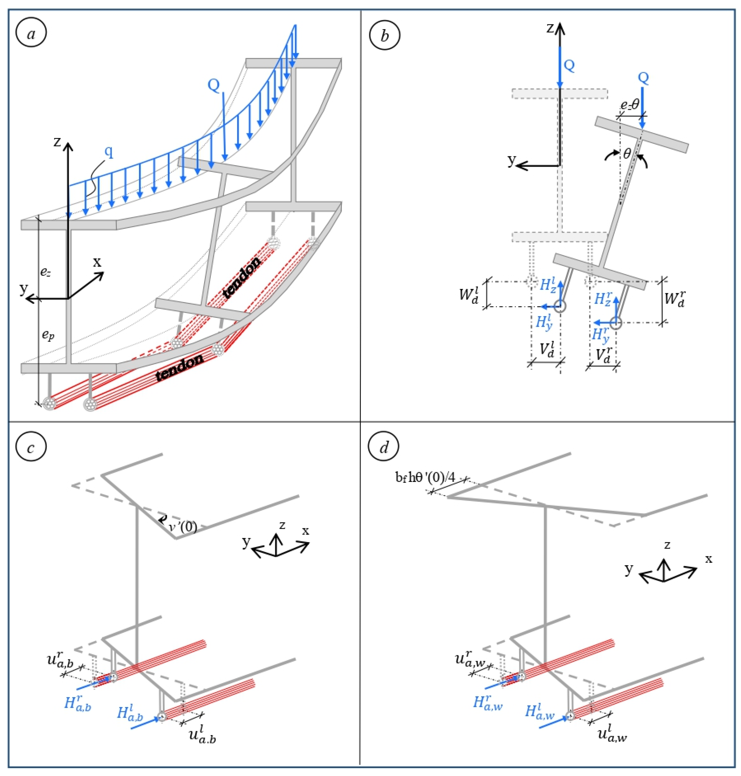
These links are named anchorages at the end cross-sections and deviators at midspan. The prestressing force is transmitted by the tendons to the beam ends via the anchorages, while the deviators act as constraints. The beam is supposed to operate in a high-temperature environment; a fair general loading system acting on it, in addition to the prestressing forces transmitted by the tendons, is represented by end bending couples M about the major inertia axis y , shown in Figure 2d, a transverse force Q at midspan, and a uniform transverse force density q , shown in Figure 3.
The total cross-sectional area of the prestressing tendons is denoted by A c , while b and ep denote the eccentricities of the tendons in the y and z directions, respectively. The mechanical characteristics of the prestressed beam in Figure 1 will be described later.
As is well known, one undesirable effect of high temperature is the degradation of the properties of the materials constituting the structural elements. Here, the beam elastic modulus E and thermal expansion coefficient α b are assumed as specified in ASCE [33]:
E = E 0 + E 0 T b 2000   l n T b 1100   ,     0   ° C < T b < 600   ° C 690 0.69 T b T b 53.5 E 0 ,     600   ° C < T b < 1000   ° C α b = 0.004 T b + 12 10 6   ° C 1 ,     T b < 1000   ° C
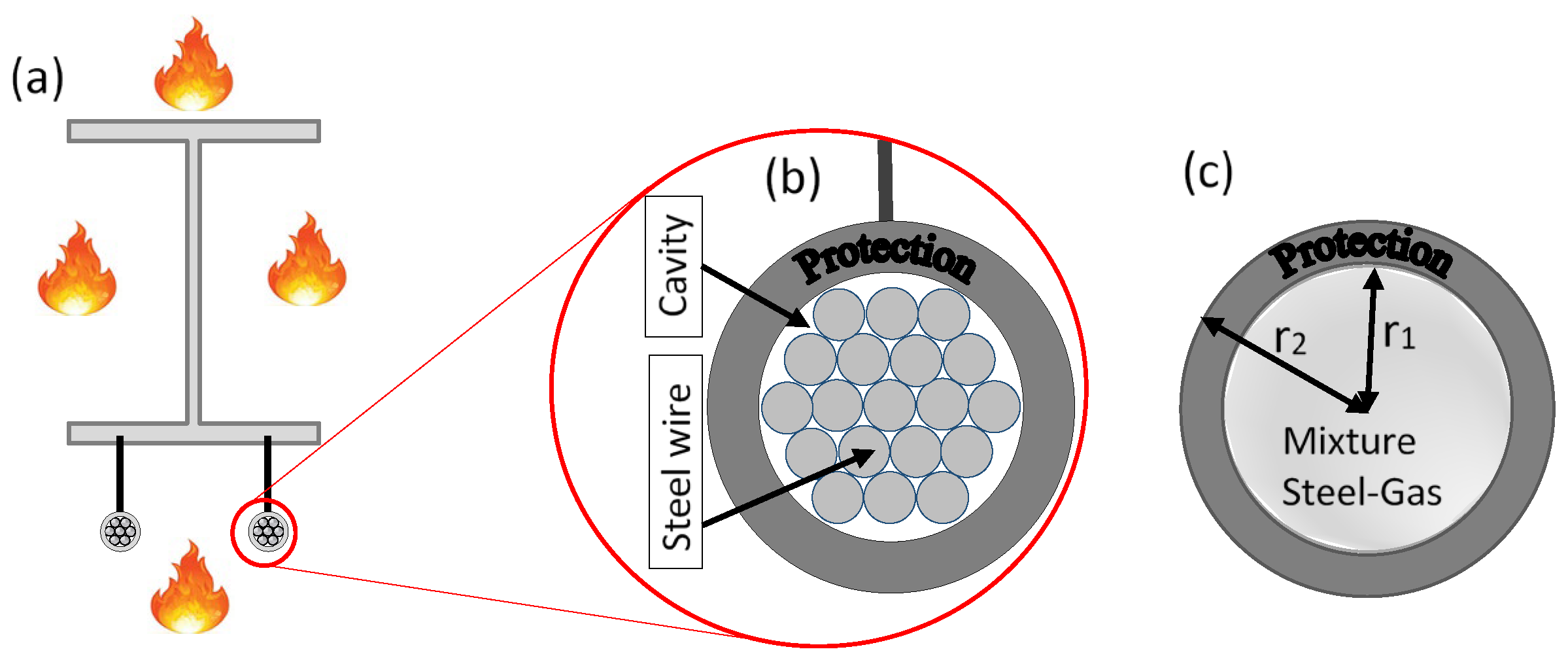
Here, E 0 and T b denote Young’s modulus at room temperature and the temperature of the beam, respectively. If the beam is supposed unprotected and exposed to fire on all sides (Figure 4a), its temperature T b is uniform and can be easily determined via the nomograms of Franssen and Vila Real [34].
Following ASCE, since the beam material remains isotropic, the shear modulus is given by the usual expression G = E / 2 ( 1 + ν ) , with Poisson’s ratio ν = 0.3 . However, the effect of the temperature is more significant on the external prestressing cables. Here, we use the elastic modulus E c and the thermal expansion coefficient α c in Du et al. [35]:
E c = E c 0 3.381 10 11   T c 4 + 1.371 10 8   T c 3 6.173 10 7   T c 2 3.245 10 4   T c + 1.007 ,   20   ° C T c 400   ° C E c 0 1.48 10 8   T c 3 + 3.342 10 5   T c 2 2.548 10 2   T c + 6.618 ,   400   ° C < T c 800   ° C α c = 2.788   10 11 T c 2 + 2.42   10 8 T c + 9.062   10 6   ° C 1   f o r   T c 800   ° C
Here, E c 0 and T c are Young’s modulus at room temperature and the temperature of the cables, which must be insulated by fire protection material to prevent structural failure (Figure 4b).
Following Du et al. [36], the internal composition of a cable is modelled as a steel–gas mixture (Figure 4c); if the cable is protected, the temperature history derived in [36] can be simplified as
T c t + Δ t = 1 ρ m c m π r 1 2 1 2 π r 2 ( h r + h c ) + ln r 2 r 1 2 π λ p 1 1 + ρ p c p d p ρ m c m r 1 T f ( t ) T c t Δ t + T c t
where r 1 , r 2 are the outer radii of the steel–gas mixture and of the protection, respectively; h r , h c represent the radiative and convective heat transfer coefficients, respectively; ρ ,   c ,   λ stand for the density, specific heat, and conductivity of the gas, steel, gas–steel mixture, and protection materials, specified by the subscripts a ,   s ,   m ,   p , respectively; Δ t is the time interval; T c t is the cable temperature at time t ; and T f ( t ) is the temperature of the environment adjacent to the external surface of the protection, typically determined using the ISO 834 model in the case of a fire. It is worth noting that this equivalence technique enables the elimination of the cavity heat transfer term from the original temperature equation in [36], while accounting for its influence. In Equation (3), the combined density ρm and specific heat capacity cm of the mixture can be calculated as
ρ m = ρ s v s + ρ a v a v s + v a ,                                 c m = c s m s + c a m a m s + m a
The density of steel ρ s = 7850 kgm−3 and of pure dry air ρ a = 1.293 = 1.64 × 10 4 ρ s kgm−3 are assumed constant, as well as their volumes v s and v a . For a strand with 19 equal wires with 7 mm diameter, v s = 7.3 × 10 4 m3, v a = 2.32 × 10 4 m3. Then, by Equation (4), the mixture density ρ m 0.76   ρ s ; further, since the gas mass in the cable gaps is much less than that of steel, the specific heat of the steel–gas mixture may be taken as equal to that of pure steel, c m c s . We also assume that:
(1)
The deviator and anchorages are rigid enough to prevent localised strain at the contact tendon–anchorage and tendon–deviator, even under remarkable prestresses. This is reasonable, due to the small dimensions and high strength of such elements, and allows us to focus on modelling how high temperatures affect the LTB of steel beams prestressed by protected and unprotected cables.
(2)
The cables are tensioned simultaneously at both ends by opposite forces, regardless of whether they have a bonded or unbonded deviator. Here, assuming tendon–deviator contact at one central point and simultaneous tensioning and blocking of cables at the anchors yields symmetrical tensions in the tendons. Conversely, if, for instance, tensioning is applied only at one end of the beam, this symmetry is not achieved.
(3)
To prevent local instability, the cross-sections are rigid in their own planes and Euler–Bernoulli beam theory still holds, as will be confirmed by nonlinear FEM simulations.
(4)
The temperature of the main member differs from that of the cables but is uniform within each element and varies over time.

2.1. Kinematics of Prestressed I-Section Beams

The prestressed cable in its relaxed state, represented by a dashed line in Figure 2a, has length L c . Once the cable is securely anchored at both beam ends, the beam undergoes the initial prestressing force E c A c ( 1 L / L c ) and experiences a contraction u 0 and an end cross-section rotation w ( 0 ) due to the cable eccentricity e p . Consequently, the cable tension becomes H 0 (Figure 2b), resulting from achieving equilibrium of force and couple on the prestressed beam immediately after the transfer of prestress from the tendon to the beam. Its value depends on the mechanical properties of both the beam and cable; details will be provided later, introducing Equation (15).
When exposed to fire (Figure 2c), the cable undergoes thermal elongation, given by α c ( T c 20 ° ) L c , which is added to its initial elastic elongation  L L c . Simultaneously, the beam experiences thermal elongation u 0 T = α b ( T b 20 ° ) L . This thermal expansion of the beam forces the cable to stretch further, thereby increasing the cable tension. The resulting additional compressive force Δ H ( T ) on the beam causes an additional elastic shortening Δ u 0 T . This effect can be further intensified by external loads M , q ,  and   Q , which induce additional end cross-section rotations   w ( 0 , T , M , q , Q ) , and/or by the eccentricity e p . The overloading of the cable due to combined thermomechanical effects contributes an extra compressive force Δ H M , which in turn leads to further shortening Δ u 0 M  of the beam, as shown in Figure 2d. To sum up, the thermal expansion of the beam introduces an additional compressive force since the cable is constrained to follow the beam deformation, thereby increasing cable tension. Conversely, if only the cable extends due to thermal effects while the beam remains unaffected, the cable force decreases, resulting in reduced compression on the beam. This interaction between the elongation of the beam and the cable, and its influence on the final prestressing force H , is captured in Equation (7).
Thus, the total elongation of the cable, considering only one half of the beam span, is:
Δ u c 2 = L L c 2 α c ( T c 20 ) L c 2 u 0 + Δ u 0 T + Δ u 0 M 2 + u 0 T 2 + e p w ( 0 , T , M )
From Figure 2d, the force-displacement relationship of a tensioned cable is
Δ u c 2 = ( H 0 + Δ H T + Δ H M ) L c 2 E c A c
From Equations (5) and (6), we can derive
H = E c A c L c L L c α c ( T c 20 ) L c u 0 + α b T b 20 L + 2 e p w 0 ,
H = H 0 + Δ H T + Δ H M ,
u 0 = u 0 + Δ u 0 T + Δ u 0 M ,
w 0 = w 0 , T , M

2.2. Variational Formulation

Our approach to detect the onset of instability of prestressed TWB with bi-symmetric cross-sections starts assuming Vlasov-like, non-linear components of the displacement
U x , y , z = u y   v cos θ y   w sin θ z   w cos θ + z   v sin θ θ , V x , y , z = v z sin θ y 1 cos θ ,   W x , y , z = w + y sin θ z 1 cos θ
In Equation (8), u ,   v ,   w are the displacement components of the centroid of the beam cross-sections along the x ,   y ,   z axes, respectively; θ is the torsion rotation; and a prime denotes derivation with respect to x . From Equation (8), Green’s strain tensor components can be easily evaluated. Following the usual variational procedure found in the nonlinear theory of thin-walled beams (e.g., Vlassov [37], Mohri et al. [38], Librescu and Song [39]), the strain energy variation δ Γ is
δ Γ = 2 0 L 2 [ E A u δ u + E I z v cos θ E I y w sin θ δ v H v δ v + E I y w cos θ + E I z v sin θ δ w H w δ w + ( E I w θ δ θ + G J θ H I 0 θ δ θ + ( E I z w v E I y w v ) cos θ δ θ ] d x
with A , I y , I z ,   I w ,   J ,   I 0 the cross-section area, moments of inertia about y and z , warping constant, Saint-Venant’s torsion inertia, and square of the radius of gyration, respectively.
Within this framework, when the prestress and the loads on the beams do not reach their critical value (fundamental equilibrium path), we may admit a linear response and superpose bending and compression. When one action exceeds its critical value, we face lateral–torsional buckling and a subsequent post-buckling path; the deformations of the beam (see Figure 3a) generate additional forces and displacements. Thus, based on the forces and displacements depicted in Figure 2 and Figure 3, and employing the positions in Equations (7b)–(7d), the variation δ Π of the external work is
δ Π = 2 0 L / 2 [ q δ w q e z θ δ θ ] d x + Q 2 δ w L 2 Q 2 e z θ L 2 δ θ L 2 H δ u ( 0 ) + ( M e p H ) δ w ( 0 ) + H y r δ V d r + H y l δ V d l + H z r δ W d r + H z l δ W d l + H a , b r δ u a , b r + H a , b l δ u a , b l + H a , w r δ u a , w r + H a , w l δ u a , w l )
Here, the superscripts r , l denote the right and left beam ends, while d , a , b ,   w denote deviator, anchorage, bending about the z -axis, and warping, respectively.
For critical loads, ‘small’ torsion rotations suffice, i.e., cos θ 1 ,   sin θ θ . Neglecting the ratio I z / I y (Mohri et al. [38], Eurocode 3 [40], Ziane et al. [41]), the stationarity of the total potential energy δ ( Γ Π ) = 0 and integration by parts in Equation (10) yields
0 L 2 { E I z v E I y w θ + H v δ v + E I y w _ + E I z v θ + H w q _ δ w _ + E I w θ G J θ + H I 0 θ E I y w v + q e z θ δ θ E A u δ u } d x + [ E A u δ u _ + E I z v δ v E I z v δ v + E I y w δ w E I y w δ w _ + G J θ E I w θ δ θ + E I w θ δ θ ] 0 L / 2 + H δ u 0 _ + M e p H δ w 0 _ Q 2 δ w L 2 _ + Q 2 e z θ L 2 δ θ L 2 + H y r δ V d r + H y l δ V d l + H z r δ W d r + H z l δ W d l + H a , b r δ u a , b r + H a , b l δ u a , b l + H a , w r δ u a , w r + H a , w l δ u a , w l = 0
In Equation (11), the underlined terms describe the fundamental state; then, we get the linear equations and the boundary conditions for a beam under axial force and bending:
  E A u _ = 0 ,     E I y w _ q _ = 0 , u 0 = 0 _               E A u 0 = E A u 0 L = H , _       w 0 = 0 _                   E I y w 0 = 0 , _ w 0 = 0 _                     E I y w 0 + M e p H = 0 , _ w L 2 = 0 _                         E I y w L 2 Q 2 = 0 _ , w L 2 = 0 _                         E I y w L 2 = 0 _
The analytical solution of the system (12) is, by the positions in Equations (7b)–(7d),
u 0 = H L E A ,    
w 0 = 2 q L 2 + 3 Q L + 24 M e p H L 48 E I y ,    
w x = q x 2 + q x L + Q x 2 E I y + M e p H E I y
Inserting Equations (13a) and (13b) into Equation (7a) provides, recalling the positions in Equations (7b)–(7d),
H = E c A c L c { L 1 + α c ( T c 20 ) L c H L E A + e p 2 q L 2 + 3 Q L + 24 M e p H L 24 E I y + α b ( T b 20 ) L }
Neglecting the influence of external load and temperature (i.e., Δ H T = Δ H M = M = q = Q = T b 20 = T c 20 = 0 ), it is possible to derive the ratio L c / L from Equation (14)
L c L = E c A c E A I y E A I y H 0 I y e p 2 A H 0 H 0 + E c A c
Inserting Equation (15) into Equation (14), by the positions in Equation (7b)–(7d), the prestressing force is
H = H 0 + 24 e p 2 A H 0 E A I y + H 0 I y E c A c α c T c 20 24 E A I y + I y E c A c + e p 2 A E c A c + ( 24 E A I y α b T b 20 + e p A 24 M + 3 Q L + 2 q L 2 ) ( H 0 + E c A c ) 24 E A I y + I y E c A c + e p 2 A E c A c
Note that Equation (16) yields the prestressing force in Kim et al. [26] by setting E c = E and T c = T b = 20   ° C , and that in Zhang [21] if mechanical and thermal loads are neglected (i.e., M = q = Q = 0 and T c = T b = 20   ° C ). Equation (16) yields the fire-induced axial force in the beam by Dwaikat and Kodur [42] (which can be considered as a prestress) by setting L = L c and e p = H 0 = 0 and neglecting the thermal expansion of the cables. Thus, an original result of ours is that a single analytical model for the beam–tendon system can both recover several results of the literature and provide new ones, resulting in efficiency in that it includes results of multiple approaches in one piece.
Since the scope of this study is to obtain critical loads, a linear approximation of Equation (8) suffices, i.e.,   U = y v θ ,     V = v z θ ,     W = y θ ; then, posing x = L / 2 , z = e p , y = ± b for the right and left tendon, we determine the displacements of the deviator–cable contact points (see Figure 3b):
V d r = V d l = v L 2 e p θ L 2 ,       W d r = b θ L 2 ,       W d l = b θ L 2  
The displacements of the anchorage–cable contact points are obtained for x = 0 :
u a , b r = b v 0 ,                     u a , b l = b v 0
However, when anchorage is achieved using rigid rods welded to the bottom flange, which is the case considered here, the warping of the end sections is partially restrained by the prestressing forces and cannot be neglected, in contrast to the case where anchorage is provided by rigid plates and warping is totally restrained, as evidenced in Hirt and Bez [43]. In this context, the anchorage displacements due to warping can be obtained from the linear approximation of Equation (8), replacing the warping function ψ  by b h / 2 , b h / 2 for the right and left anchors, respectively, so that
u a , w r = b h 2 θ 0 ,     u a , w l = b h 2 θ 0
Consequently, the virtual displacements are
δ V d r = δ V d l = δ v L 2 e p δ θ L 2 ,   δ W d r = b δ θ L 2 ,   δ W d l = b δ θ L 2 ,   δ u a , b r = b δ v 0 ,   δ u a , b l = b δ v 0 ,   δ u a , w r = b h 2 δ θ 0 ,   δ u a , w l = b h 2 δ θ 0  
If we assume that the prestressing force H in the fundamental state, Equation (16), is unchanged near its critical value, the forces on the beam at the deviator, Figure 3b, are
H y r = H y l = H 2 V d r L 2 = H L v L 2 e p θ L 2 ,     H z r = H 2 W d r L 2 = H L b θ L 2 ,           H z l = H 2 W d l L 2 = H L b θ L 2
The forces due to the variation of tendon tension induced by the post-buckling rotation v 0 , Figure 3c, and those due to the warping of the beam end, Figure 3d, are
H a , b r = E c A c 2 L c 2 u a , b r = E c A c 2 L c 2 b v 0
H a , b l = E c A c 2 L c 2 u a , b l = E c A c 2 L c 2 b v 0 ,  
H a , w r = E c A c 2 L c 2 u a , w r = E c A c 2 L c 2 b h 2 θ 0 ,      
H a , w l = E c A c 2 L c 2 u a , w l = E c A c 2 L c 2 b h 2 θ 0
It should be remarked that the expressions in Equations (22c) and (22d) are another point of novelty of our study, since we consider warping effects sometimes disregarded in the literature on prestressed beams (see, e.g., Kim et al. [26]). This oversight can lead to wrong results, particularly for beams with cross-sections prone to warping like the I-profiles that we consider. These new results are in closed form, which is non-trivial and may be important from the point of view of design for applications. This effect, however, is meaningless for mono-symmetric beams with single tendons, i.e., b = 0 .
As known in stability analyses, in the search for a post-buckling equilibrium path it is necessary to consider that the distributed load q and the concentrated force Q induce torsional couples q e z θ , ( Q / 2 e z ) θ ( L / 2 ) , resulting from post-buckling torsion (Figure 3b).
Since we consider simply supported profiles, the kinematic descriptors of the buckled beam that automatically satisfy the boundary conditions in Equation (11) can be approximated by the ordinary harmonic modes of bending and torsion buckling
v = v 0 sin n v π x L ,     θ = θ 0 sin n t π x L
with v 0 , θ 0 the relevant modal amplitudes, and n v ,   n t the bending and torsion mode number. Indeed, if buckling occurs at fundamental or higher-order modes with n v = n t , the critical load should be calculated by inserting Equations (23), (22), (21), (20), and (13c) into Equation (11), integrating it according to Galërkin’s method and collecting the coefficients of the virtual quantities δ v 0 ,   δ θ 0 . Since these quantities are independent and arbitrary x [ 0 ,   L ] , we obtain the algebraic balance equations
π 2 n v 2 π 2 n v 2 L c E I z L c H L 2 + 8 E c A c b 2 L + 8 H L c L 2 sin n v π 2 2 4 L c L 3 v 0 + + 6 Q L + 16 e p H ( 1 ) n v + n v 2 π 2 4 24 e p H 2 + n v 2 π 2 3 L Q n v 2 π 2 + 3 2 L 2 q 24 M n v 2 π 2 96 L θ 0 = 0 6 Q L + 16 e p H ( 1 ) n v + n v 2 π 2 4 24 e p H 2 + n v 2 π 2 3 L Q n v 2 π 2 + 3 2 L 2 q 24 M n v 2 π 2 96 L v 0 + [ π 2 n v 2 ( π 2 n v 2 E I w H I 0 L 2 + G J L 2 ) + L 4 q e z 4 L 3 + π 2 n v 2 E c A c b 2 h 2 + ( q e z L + 4 H e p 2 + b 2 ) L c L sin n v π 2 2 2 L c L 2 ] θ 0 = 0
Equation (24) can be reduced to an eigenvalue problem via the relevant Jacobian matrix, the proper values of which yield the critical loads. This is achieved by incorporating the expressions for the initial length of the cable L c and the prestressing force H given by Equations (15) and (16), while also accounting for the properties of the materials constituting the structural elements in Equations (1) and (2).
It is important to note that Equation (23) cannot be restricted to the buckling modes with n v = n t alone, as this may yield inaccurate results if the actual buckling occurs at a different mode. Therefore, the critical load must be calculated considering n v n t . The generalised algebraic balance equations for this scenario are provided in Appendix A.

3. Results and Discussion

To validate the model, comparisons with several results in the literature will be presented. To this aim, four beam types are considered, see Figure 5, with Young’s modulus E 0 = E c 0 = 206   GPa for beams and cables at room temperature. To avoid local buckling, anchors and deviators are posed infinitely rigid, with 6   mm radius circular cross-section.

3.1. Prestressed Beams Under Mechanical Loading

We first compute critical loads neglecting thermal effects, i.e., we consider mechanical buckling only, assuming T c = T b = 20   ° C . The results are then compared to those of Kim et al. [25,26] about the beams-1 in Figure 5 with length L = 12   m and total cable area A c = 1257   m m 2 . Then, in Section 3.2, we adopt A c = 1423.205   m m 2 and A c = 1461.67   m m 2 for single- and two-tendon beams, corresponding to cables with 37 and 2 × 19 wires, respectively.
The relative errors between the critical end moments obtained from our model and those derived following various methods by Kim et al. [25,26] are given by
  Δ 1 = O u r   r e s u l t K i m s   ( e x a c t ) M i n ( O u r   r e s u l t , K i m s ) ,   Δ 2 = O u r   r e s u l t K i m s   ( F E M ) M i n ( O u r   r e s u l t , K i m s   ) ,   Δ 3 = O u r   r e s u l t K i m s   ( R i t z ) M i n ( O u r   r e s u l t , K i m s  
The comparison based on Equation (25) is presented in Table 1 and is satisfactory; the maximum error, Δ 1 = 4.89 % , occurs for a two-tendon beam with prestressing force H 0 = 400   kN , confirming the efficiency of our approach.
Notably, this error slightly increases with b and H 0 because of warping on the cable tension; see Equation (22). This effect is neglected by other studies in the literature, while we can account for it; thus, we cannot thoroughly replicate other results, which must on the other hand be considered less reliable than ours. More details will be presented later.
The comparison based on Equation (25) for beams subjected only to the prestressing force is in Table 2; remarks like above hold, and the maximum relative error is Δ 2 = 4.21 % .

3.2. Prestressed Beams Under Thermomechanical Loading

Although prestressed steel structures offer a substantial increase in terms of stability issues, their susceptibility to extreme temperatures is a notable concern. One of the most serious undesirable effects of high temperature is the degradation of the mechanical properties of the constituent materials, especially those of the pre-stressing cables. Despite the evident practical importance of this problem, there are almost no studies devoted to the analysis of the LTB of prestressed I-section beams under high temperatures. Therefore, to further validate our results for this scenario, we conduct FEM simulations using the ABAQUS software (Version 6.4) [44], with B31OS (quadratic open-section beam) element type for the beams, B31(linear beam) for the anchors and deviators, and T3D2 (linear 3-D truss) for the tendons. In FEM, it is well-known that the accuracy of the results increases as the mesh size decreases, within the limits of acceptability of the finite element considered. According to Ascione and Feo [45], convergence for beam elements is achieved more rapidly compared to shell or solid elements. In this study, the maximum mesh of the elements was controlled within 120 mm to ensure the calculation accuracy of the model. For the boundary conditions, the translational degrees of freedom (U2, U3) at the left end node of the beam are fixed, meaning there is no movement allowed in the vertical and horizontal directions. The rotational degree of freedom (UR1) at this node is also fixed, implying no rotation around the longitudinal axis. At the right end node, the axial displacement (U1) is fixed in addition to (U2, U3, UR1). This set of constraints ensures that the FEM model accurately simulates a simply supported beam. Recall that all the FEM data mentioned above are already in Kim et al. [25,26] for prestressed beams at room temperature. However, to account for the simultaneous mechanical and thermal deformations of the cable (which typically present a significant modelling challenge), we formulate, as an original point, an equivalent thermal expansion coefficient as follows:
ε c = ε M + ε T = L C L L C + α c T C 20 = T C L C L T C L C + α c T C 20 T C _ = α _ T c  
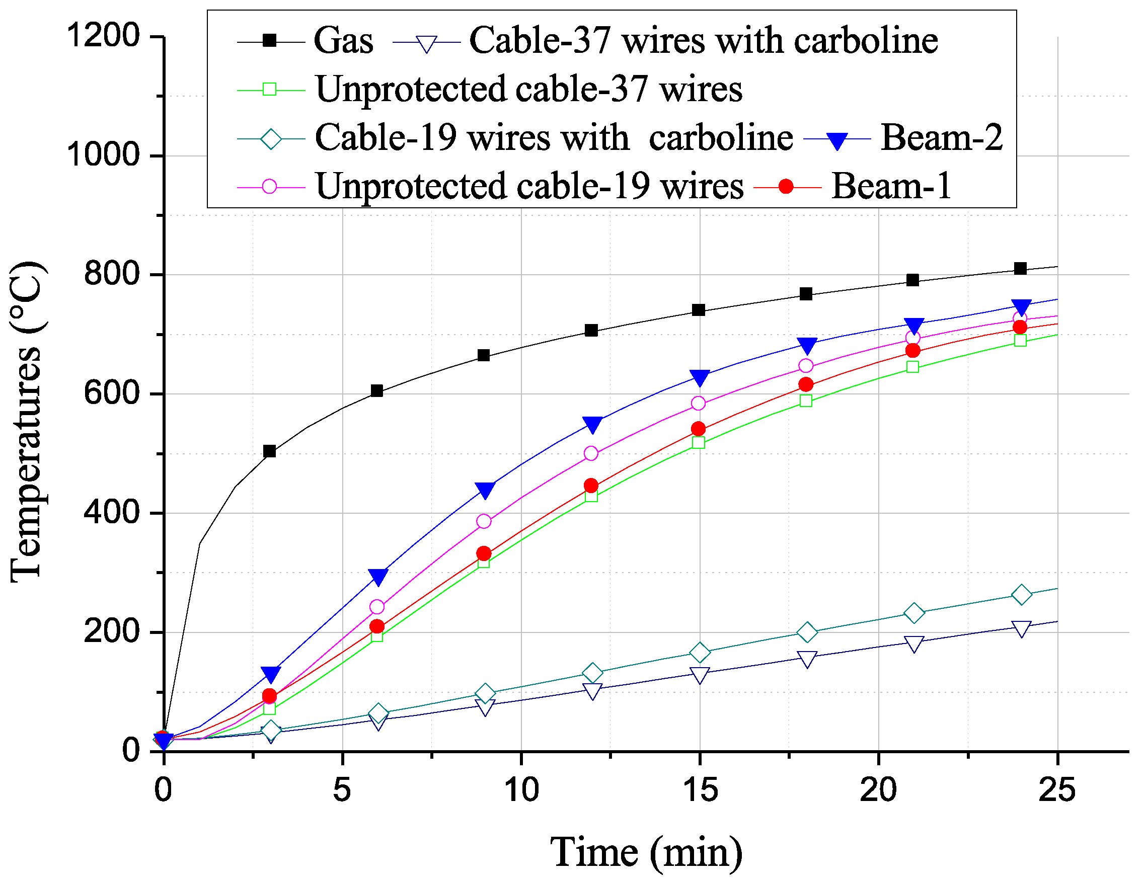
where ε c ,   ε M ,   ε T represent the total, mechanical, and thermal deformation of the cable, respectively, while the other symbols were introduced previously; the underlined term in Equation (26) provides the equivalent thermal expansion coefficient of the cable for the FEM model. This coefficient as well as the material properties in Equations (1) and (2) need to be discretised by a temperature increment of 20 °C before being introduced into the ABAQUS software (i.e., material with temperature-dependent data). The associated temperature data, shown in Figure 6, derive from Equation (3). In the FEM procedure that implements the structural model presented here, the critical loads are obtained in two steps: the first (“Static, General”) is computed using temperatures introduced as a “Predefined Field”, while the eigenvalues are obtained in the second step (“Buckle”). We assume a constant ratio L / b f = 40 for all the prestressed beams, supposed to be exposed on all sides to a fire according to the standard ISO 834. The temperatures of the unprotected beam are uniform, can be easily obtained from the tables and nomograms in Franssen and Vila Real [34], and are very close to those given by the formula in Simoncelli et al. [46]. The cable temperature results from Equation (3), with and without the application of 1   c m thick spray fire resistive material (SFRM) Carboline type-5MD, the thermal properties of which are provided by the test data in [47]. This material proved effective in protecting beams from fire; since its performance for cables is unexplored, we had an opportunity to evaluate its suitability as a cable protection material. Thus, the evolution of temperatures on gas, beams, and cables as a function of fire duration, shown in Figure 6, enables us to obtain the critical loads in the time domain.
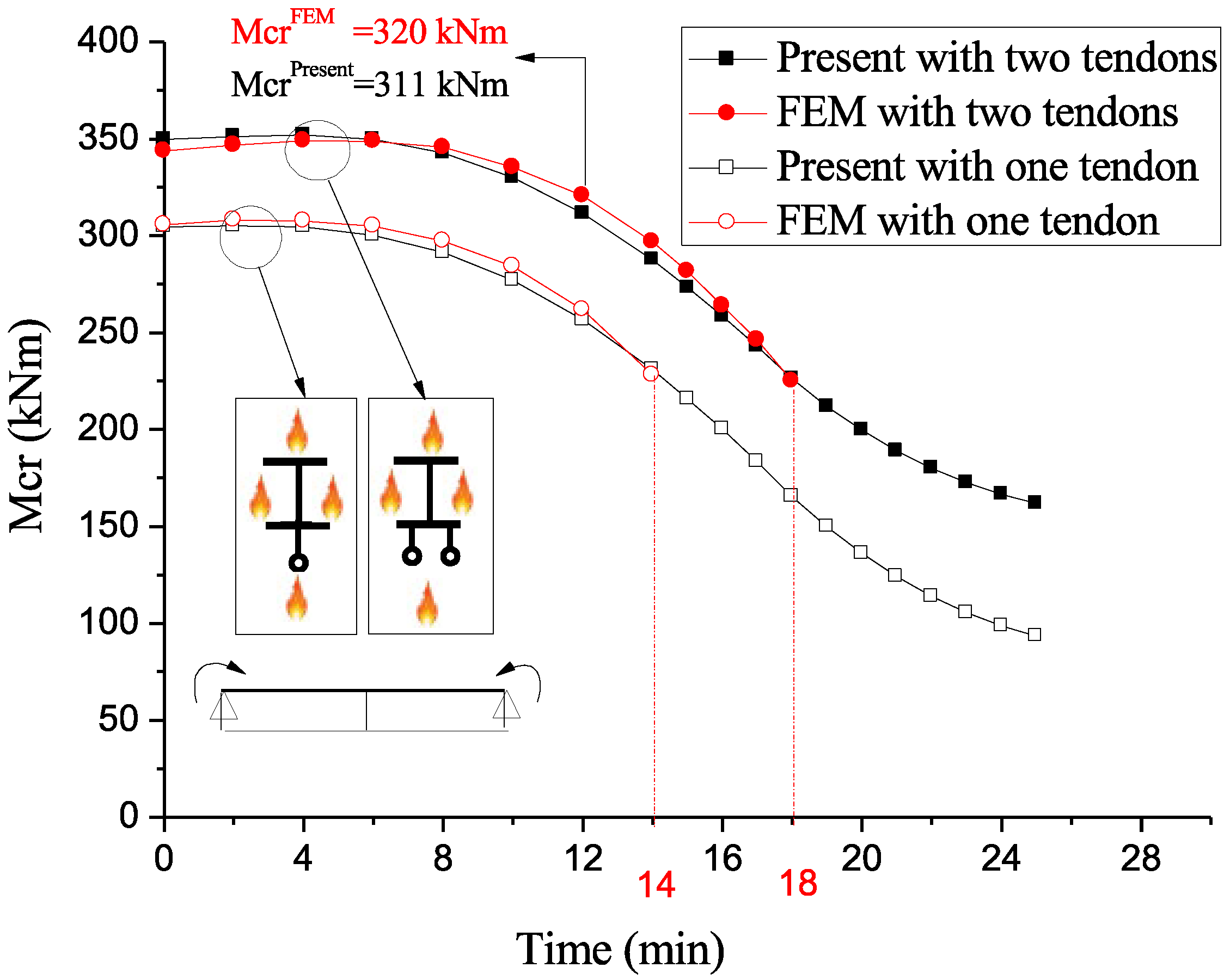
Figure 7 shows good agreement of our results with the FEM ones (the maximum relative error does not exceed 3%), yet our algorithm computes critical couples for almost infinite fire durations (the limits lie in the admissibility of the assumptions in Section 2).
Indeed, ABAQUS stops at 14 min of fire exposure for beam-1 with one tendon and at 18 min for beam-1 with two tendons (which are the values highlighted in red in Figure 7), showing the error message “The Eigenvalues Cannot Be Found. This Could Be Caused Due To Instabilities in the Base State”. We can instead predict the behaviour of the system for rather larger time durations; this is another original point and strength of our model with respect to others in the literature. Of course, wishing to make comparisons with FEM, we will not consider time durations that largely exceed the FEM capabilities for time durations, to have clearer graphical representations of curves that are compared.
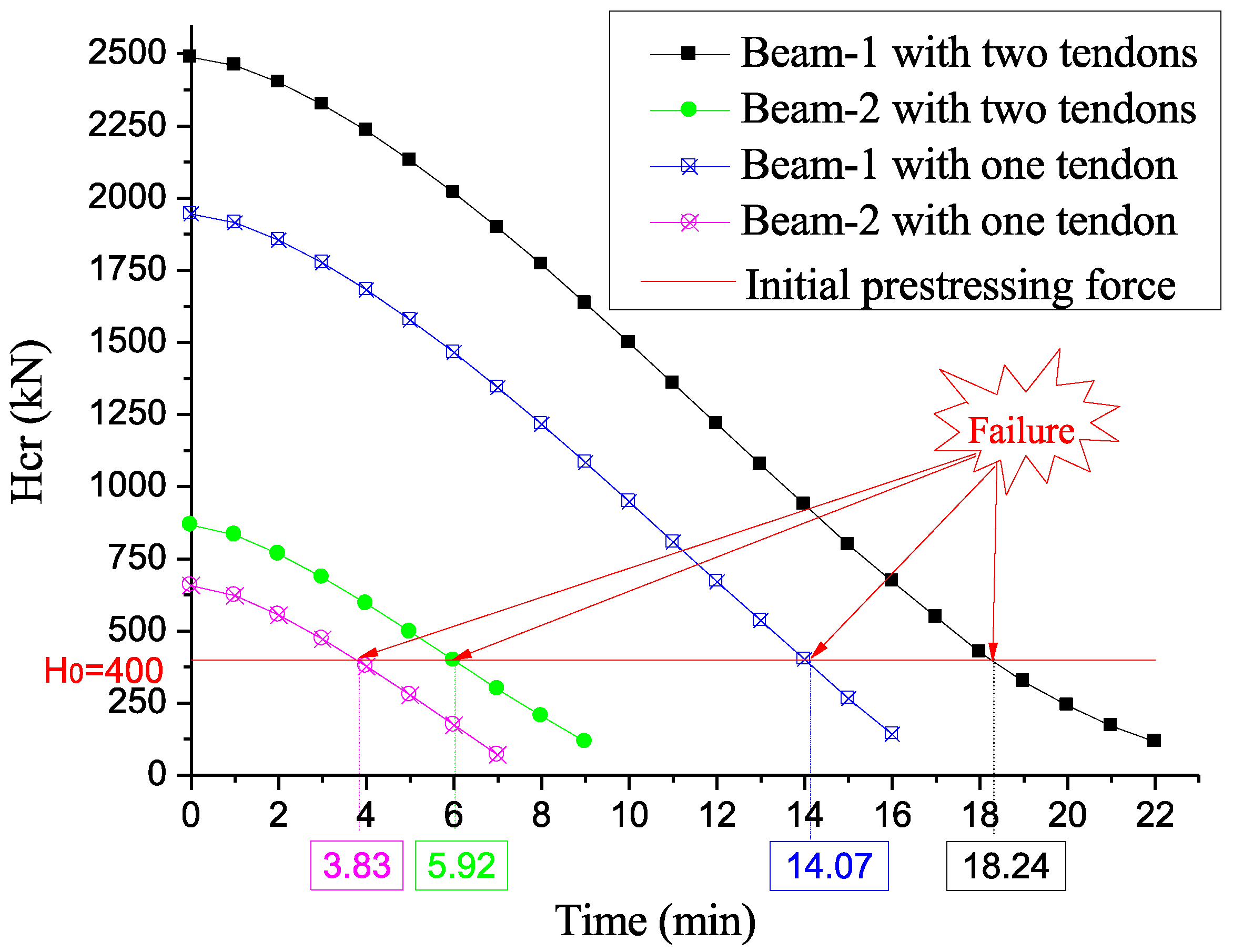
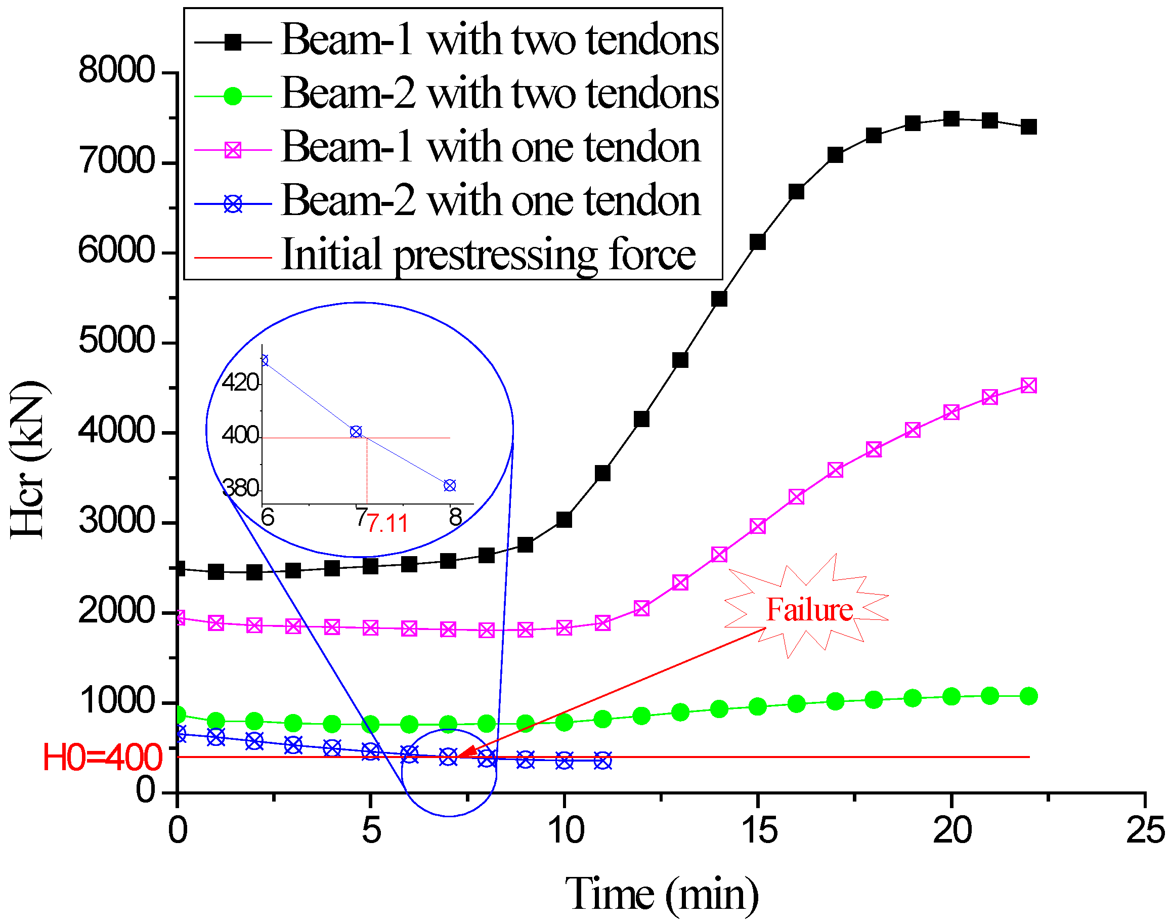
In addition, this behaviour of the commercial code prompted us to perform an investigation on additional instability modes, focusing on the critical prestressing forces. This will be shown in Figure 8 and Figure 9 and commented upon later; we anticipated that it was necessary to introduce the additional condition H 0 < H c r into our algorithm, which will thus be considered in the other cases presented below.
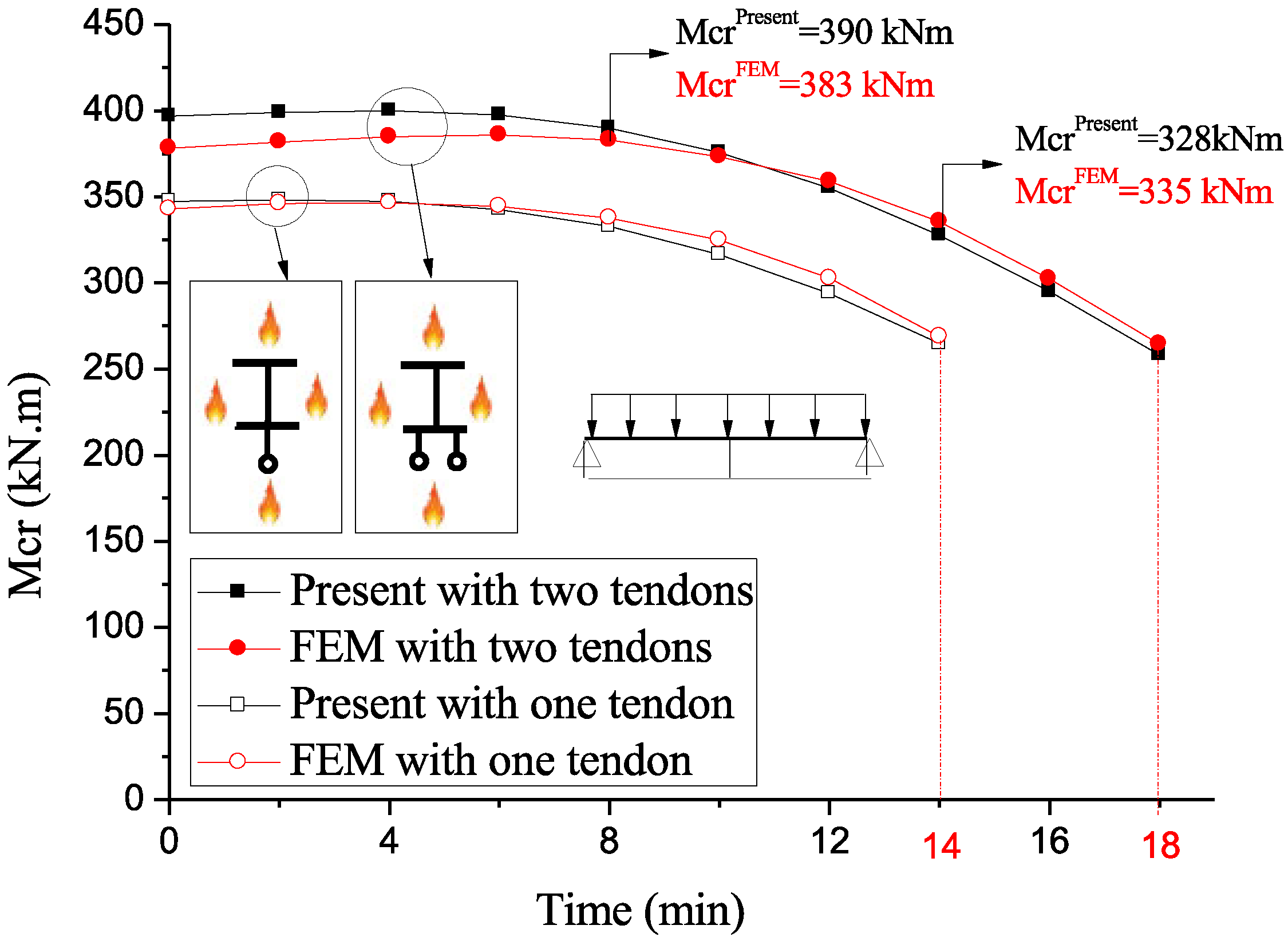
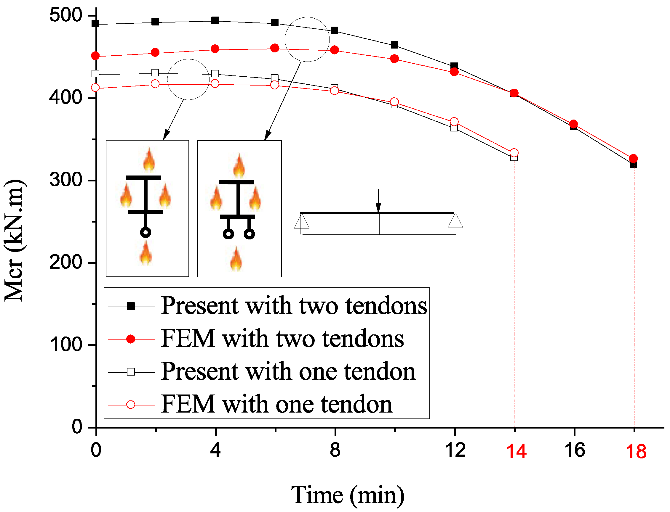
Thus, the procedure for the next cases can be summarised in three steps: (1) critical moment calculation ( M c r ): by eliminating the loads q , Q and fixing the initial prestressing force H 0 , we obtain the critical concentrated couple M c r at an instant t , inducing buckling under a positive couple; (2) critical prestressing force calculation ( H c r ): since the beam can buckle under a negative moment induced by the critical prestressing force, we solve the problem by keeping H 0 as the unknown while imposing values on M at T c and T b ; and (3) validation: when M c r and H c r are obtained at time   t , the conditions M c r > imposed bending couple and H c r > H 0 must hold; if not, the calculations are stopped. We iterate calculating M c r and H c r at t + Δ t to obtain the critical curve over time. Figure 7, Figure 8, Figure 9, Figure 10 and Figure 11 show that the disparity between our results and the FEM ones (the limit time durations of the commercial codes are again highlighted in red) is slightly greater for double-tendon beams-1 compared to the single-tendon ones. These differences are within acceptable limits, reaching 7% in the former case and 4% in the latter.
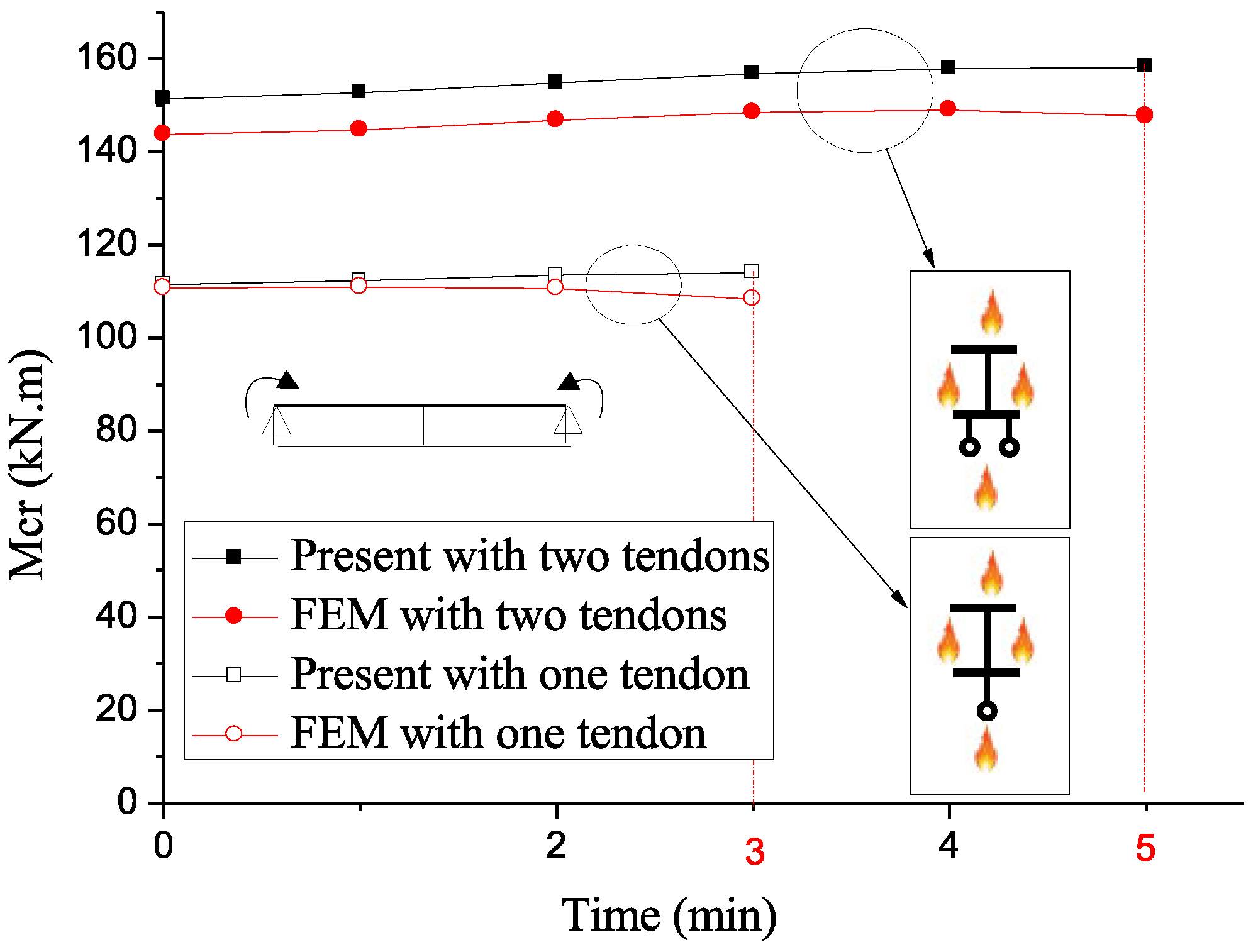
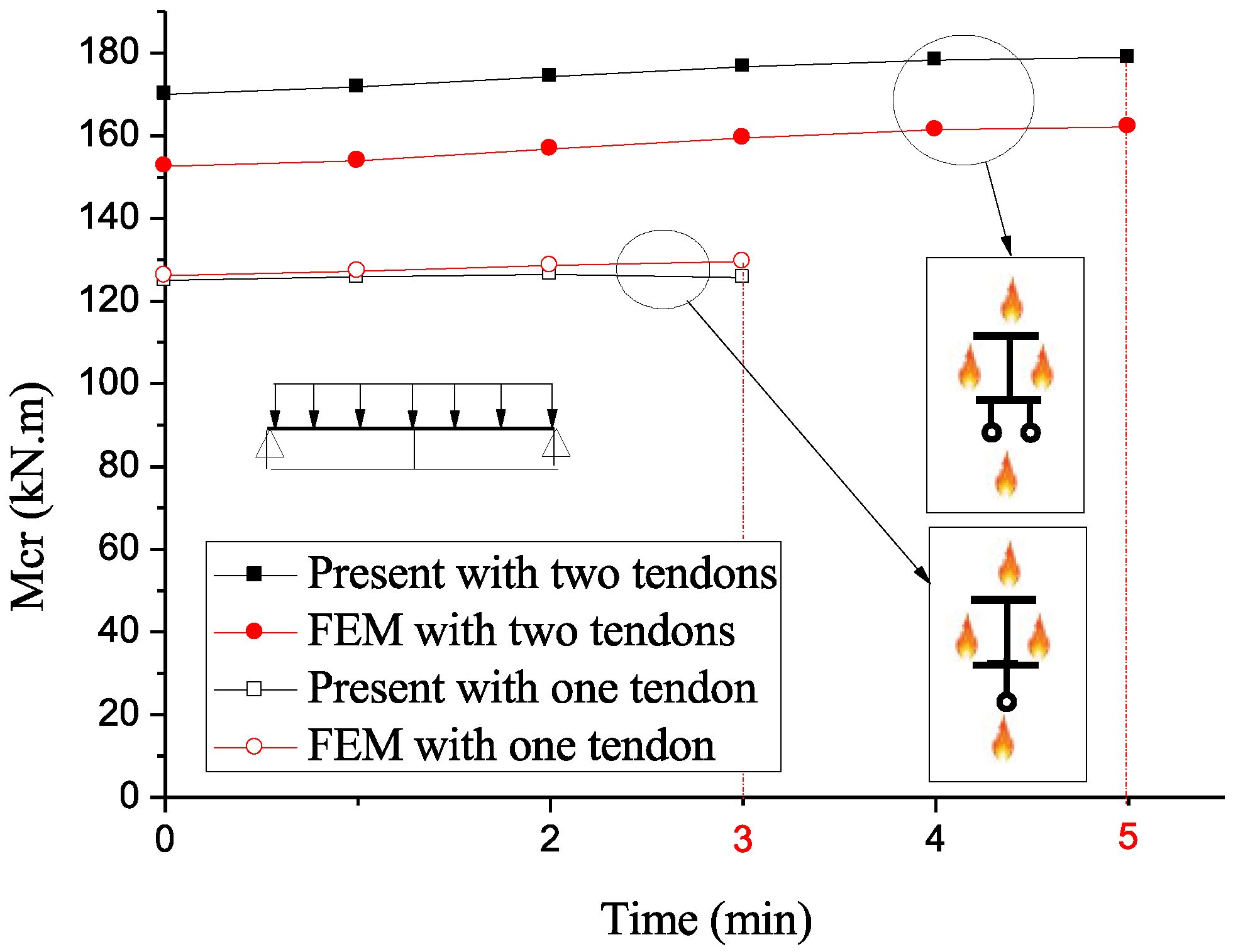
Figure 12, Figure 13 and Figure 14 show that the gap of FEM results with ours is remarkable for beams-2 with two tendons: for a point load, a peak error of 17% is reached. On the other hand, the top relative error does not exceed 4% for one-tendon ones, due to the tendons’ over-tension due to warping of the end sections, more significant for beams-2 than for beams-1.
The results of the investigation on the critical prestressing forces are in Figure 8 and Figure 9; they show that beyond specific durations (i.e., 3.83 min for beams-2 with one tendon, 5.92 min for beams-2 with two tendons, 14.07 min for beams-1 with one tendon, and 18.24 min for beams-1 with two tendons), the critical prestressing forces fall below the initial value H 0 = 400   k N . Consequently, we must introduce the possibility of the additional condition H 0 < H c r into our algorithm, as already said. In fact, the specific durations associated with the present approach depend on the values H c r computed without external loads (i.e., M = q = Q = 0 ). Designers must specify these loads (dead and live loads applicable to prestressed beams in a fire situation), which might result in longer durations.
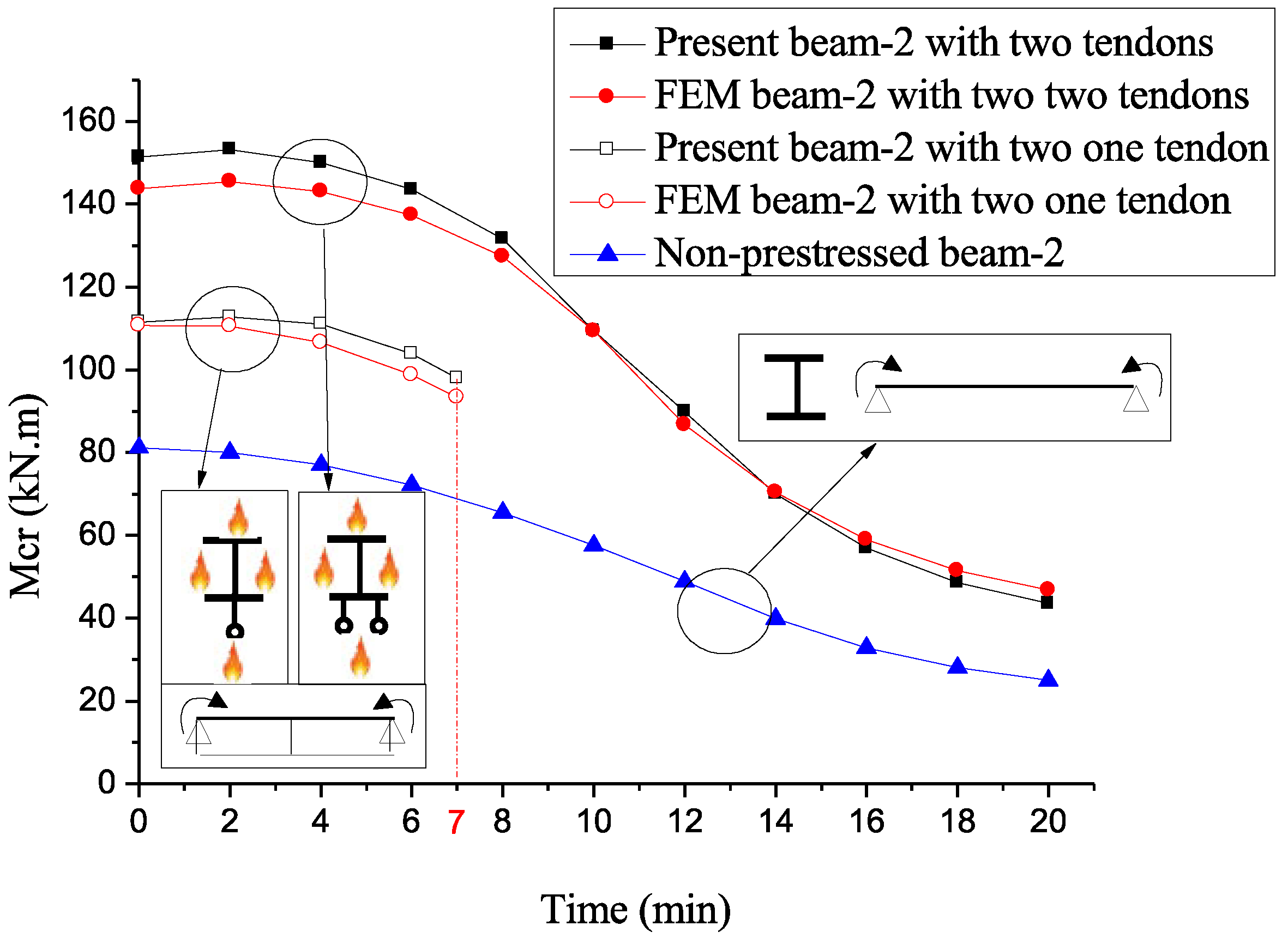
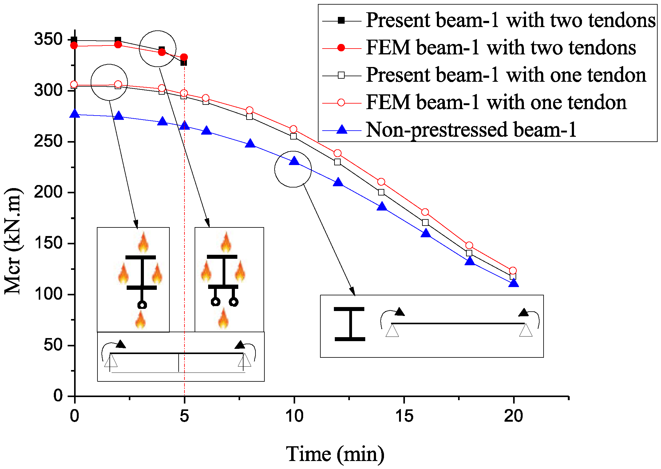
The results predicted by the present approach for prestressed beams with unprotected cables are displayed in Figure 15 and Figure 16, exhibiting a reasonable agreement with the values from the FEM analysis and also indicating that, unlike the beams with protected cables in Figure 12, Figure 13 and Figure 14, beams-2 with two unprotected tendons and beams-1 with a single unprotected tendon have higher stability duration. This is attributed to the diminished temperature differences between the cables and the beams, leading to a reduction in the cable tensile force (see Figure 6). Nevertheless, the critical couples for the protected beams retain the greatest values. Furthermore, Figure 15 and Figure 16 show that the effect of prestress and of the number of tendons decreases with increasing fire duration. However, we observe that the curve related to the beams-2 with one tendon in Figure 15 and that related to the beams-1 with two tendons in Figure 16 are short in duration. The former stops at 7 min since H c r < H 0 (see above and Figure 9), while the latter does not exceed 5 min, despite H c r > H 0 . Note that all critical couples in Figure 7, Figure 8, Figure 9, Figure 10, Figure 11, Figure 12, Figure 13 and Figure 14 and Figure 15 and Figure 16 are obtained in the first LTB mode (nv = nt = 1), while the critical prestressing forces in Figure 8 and Figure 9 are obtained for different modes according to the values of nv and nt in Table 2.
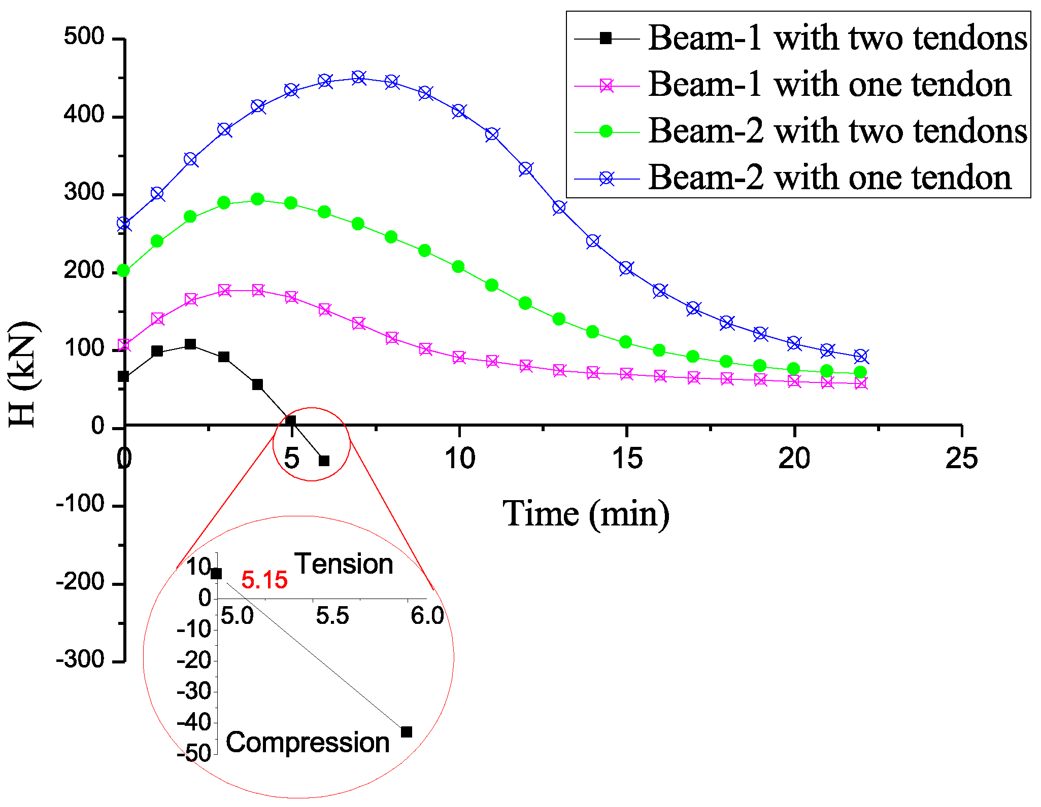
Figure 17 shows that, from minute 5, H becomes compressive on the unproctected cables, since their thermal expansion is higher than that of the beam (Figure 6). Thus, in the algorithm we must add that: if H < 0 , then the beam is assumed non-prestressed.

3.3. FEM Nonlinear Analysis

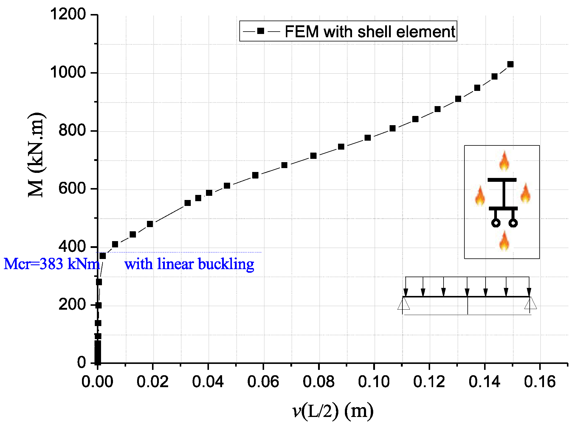
To improve the previous results, obtained by a linear analysis, an FEM simulation by the commercial code ABAQUS [44] with geometric non-linearity was performed, using the shell element S8R, typical of members with deformable sections. In the linear buckling analysis above, the beam element B31OS was used for meshing main members with rigid sections instead. The shell element was specifically used to check the cross-section shape at high temperatures. For the sake of space, we focused on studying beam-1 (wide-flange, H-cross-sections) with two tendons and one central deviator under a uniform load at two fire exposure times, i.e., 8 and 14 min. The main member was meshed with 6 shell elements for the flanges, 6 shell elements for the web, and 200 shell elements along the axis. For the remaining parts of the system (deviator, anchorages, and tendons), the same element types used in the FEM linear analysis were retained for the nonlinear analysis. In all computations, a concentrated torque of 50 Nm, representing the initial imperfection, was applied at midspan. The load–displacement curves were obtained in two steps, the first (“Static, General”) computed using temperatures and imperfection, and the second (“Static, Riks with geometric nonlinearity”) providing the load factors and displacement.
Figure 18 and Figure 19 show the pre- and post-buckling equilibrium paths ( M ,   w ( L / 2 ) ) at the beam midspan after 8 and 14 min of fire exposure, respectively. Unlike non-prestressed beams at room temperature, where buckling loads are usually identifiable at the intersection of linear and nonlinear paths, locating these loads in the nonlinear equilibrium curves of prestressed beams under fire is challenging, due to the complex interactions among loads, thermal effects, and prestressing forces.
Figure 20 and Figure 21 provide clearer insights, showing the evolution of the bending couple with respect to the lateral displacement at midspan ( M ,   v ( L / 2 ) ) . It is apparent that the critical couples given by linear buckling analysis, i.e., 383 kNm at 8 min and 335 kNm at 14 min (see Figure 10), closely approximate the values given by the nonlinear analysis.
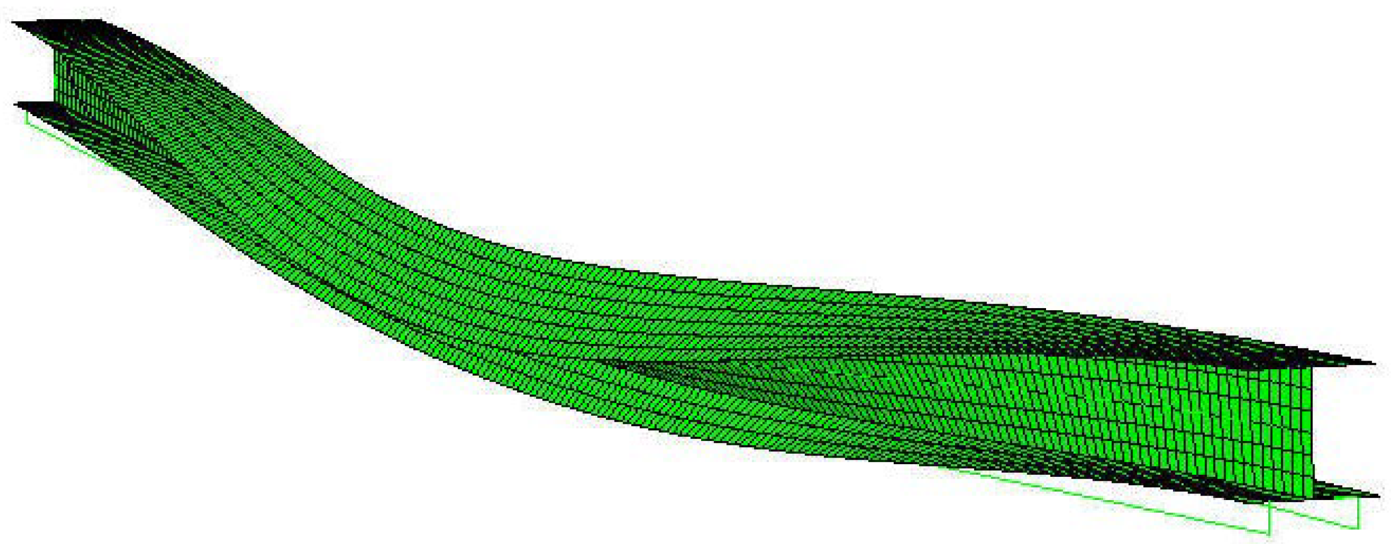
Further, we remark that the shape of the beam cross-section is unaffected by high temperature, as can be clearly seen in Figure 22, which shows the post-buckling shape of the beam after 14 min of fire exposure, corresponding to a beam temperature Tb = 509 °C.
A transient state analysis was also performed to validate our results. The same element types and parameters of the steady state analysis quoted earlier were carried over to the transient analysis. For consistency, we applied end couples of 311 kNm (corresponding to a fire exposure time of 12 min in the linear buckling analysis, as shown in Figure 7) to assess the beam behaviour in the transient analysis. In this FEM analysis, the displacement–time curves were obtained in two steps. The first step (“Static, General”) was calculated using end couples of 311 kNm and the same imperfection. In the second step (“Static, Riks with geometric nonlinearity”), the temperatures of the beam T b and the cable T c were introduced as predefined fields. For this step, we set T b = T c = 1 °C and used tabular-type amplitudes to incorporate the time–temperature data from Figure 6.
Figure 23 illustrates the evolution of midspan lateral displacements and twist angles over the fire duration for beam-1, as determined from the transient analysis. We note that the beam, under end couples of 311 kNm, bifurcates around the 12 min mark. This outcome confirms the results obtained by the present method, particularly those of Figure 7, where the critical moment of 311 kNm corresponds to a fire duration of 12 min.
It is important to note that the behaviour of prestressed steel beams is not covered by the two main standards (i.e., ASCE [33] and Eucode3 [40]) due to its complex nature. This complexity arises from the interaction between the cable (tension member) and the beam (member under combined bending and compression). The present approach can assist designers of metal structures to verify the resistance of prestressed beams exposed to fire (in temperature, time, and resistance domains). For instance, the final prestressing force can contribute to verify the cable. Further, the critical moments provided by our approach are key in computing the non-dimensional slenderness λ L T at both room temperature and in a fire situation, ultimately determining the reduction factor χ L T . However, it is imperative to first establish the ongoing validity of χ L T for prestressed beams, as stipulated by the standards [33,40]. Its well-known expression is
χ L T = 1 ϕ L T + ϕ L T 2 λ L T 2 ,     ϕ L T = 0.5 1 + η + λ L T 2 ,
where η is the generalised imperfection factor. Equation (27) derives from a nonlinear analysis based on the Ayrton–Perry formula [48], including contributions of geometric imperfections and residual stress. This validation will be key in our upcoming work.

4. Final Remarks

We have investigated the fire effect on the stability of simply supported prestressed I-section steel beams that were denominated by the labels 1 and 2 to encompass both wide- and narrow-flange cross-sections. To this aim, we considered various loading conditions, and we proposed an analytical approach that we implemented numerically to calculate the critical values inducing the onset of LTB. Such an approach, though based on kinematic assumptions that are well-known in the literature, extends previously published theoretical and technical approaches, since it considers more effects (e.g., the warping of end sections on the tendons’ tension) and summarises the outcomes of several models into just one. Our methodology consists of two main steps: (i) calculation of the actual prestressing force involves the linear equilibrium of the beam subjected to a combination of axial force and bending, considering the initial prestressing force, the loads, and the thermal effects on the beam and cables; and (ii) the eigenvalues yielding the critical loads are obtained by Galërkin’s method applied to a non-linear system of equilibrium equations.
Our approach leads to some interesting conclusions. Firstly, we were able to effectively address the simultaneous thermal and mechanical deformation of the cable in FEM analysis by employing our proposed equivalent thermal expansion coefficient in a well-established commercial code. Secondly, the numerical results obtained by our model for wide-flange beams are in good agreement with FEM ones, while the stability duration of narrow-flange profiles with protected cables is sensibly lower than that of wide-flange beams. Regarding some remarkable effects of the tendons, the growth in tendons’ tension caused by the warping of the end sections induces a pronounced disparity between our results and those of the FEM for beams with two protected tendons, particularly for narrow-flange profiles subjected to a concentrated force. Finally, if the cable temperature is slightly lower than that of the beam, stability duration is extended, while if the cable temperature exceeds that of the beam, the prestressing becomes ineffective.
Our approach, though limited because of some of the starting assumptions, represents a basic way to encompass several effects and yet to be able to provide closed-form results. It is unnecessary to remark how such results can assist designers of metal structures to verify the resistance of prestressed beams exposed to fire in temperature, time, and resistance domains. We stress, however, that by a FEM nonlinear analysis we were able to show that, up to a remarkable temperature, the standard Vlasov’s and Bernoulli–Euler kinematic hypotheses for beam modelling are still valid. Thus, as commented above, refinements of the approach shall go other ways.
Further developments of the present investigation shall be manifold. On the one hand, it is advisable to understand how to encompass more general behaviours by relaxing some of the assumptions provided here; for another thing, it would be important to check whether other FEM codes can provide more accurate benchmark numerical solutions; and, last but not least, it would be useful to design and realise an experimental campaign to have actual results from laboratory tests.

Author Contributions

Conceptualization, N.Z. and G.R.; methodology, N.Z. and G.R.; software, A.M., M.Z. and R.Z.; validation, N.Z., S.A.M. and G.R.; formal analysis, N.Z., S.A.M. and G.R.; investigation, N.Z. and G.R.; resources, N.Z.; data curation, N.Z. and G.R.; writing—original draft preparation, N.Z. and G.R.; writing—review and editing, N.Z. and G.R.; visualization, N.Z., S.A.M. and G.R.; supervision, N.Z. and G.R.; project administration, N.Z. and G.R. All authors have read and agreed to the published version of the manuscript.

Funding

This research was funded by the Italian Ministry of University and Research grants PRIN 2022Y2RHHT-002PRIN and PNRR P2022ATTAR.

Data Availability Statement

The original contributions presented in the study are included in the article, further inquiries can be directed to the corresponding author.

Conflicts of Interest

The authors declare no conflicts of interest.

Appendix A

If n v n t ,
π n v π 3 n v 3 L c E I z π n v L c H L 2 + 8 π n v E c A c b 2 L + 8 H L c L 2 sin n v π 2 2 4 L c L 3 v 0 + [ 8 L π n v n t 3 n t 2 n v 2 q L + Q Q cos n v π 2 cos n t π 2 8 L π n t n v 3 n t + n v 3 + 4 L π n t 2 Q n v 4 n t 4 16 H e p π n t n v 3 n t + n v 3 sin n v π 2 sin n t π 2 8 L π n t n v 3 n t + n v 3 + [ n t 4 π 2 + 8 2 π 2 n v 2 n t 2 + π 2 n v 2 + 24 n v 2 n t 3 q L 2 8 L π ( n t n v ) 3 ( n t + n v ) 3 + 2 π 2 n t 3 n t 2 n v 2 2 4 M + Q L 8 π 2 n t 3 H e p n t 2 n v 2 2 ] sin n v π 2 cos n t π 2 8 L π ( n t n v ) 3 ( n t + n v ) 3 + [ n t 4 π 2 + 2 π 2 n v 2 24 n t 2 8 + π 2 n v 2 n v 2 n v n t 2 q L 2 8 L π ( n t n v ) 3 ( n t + n v ) 3 + 2 π 2 n t 2 n v n t 2 n v 2 2 4 M + Q L + 8 π 2 n t 2 n v H e p n t 2 n v 2 2 ] sin n t π 2 cos n v π 2 8 L π ( n t n v ) 3 ( n t + n v ) 3 ] θ 0 = 0 ,
[ 8 L π n t n v 3 n t 2 n v 2 q L + Q Q cos n v π 2 cos n t π 2 8 L π n t n v 3 n t + n v 3 + 4 L π n v 2 Q n v 4 n t 4 16 H e p π n t n v 3 n t + n v 3 sin n v π 2 sin n t π 2 8 L π n t n v 3 n t + n v 3 + [ π 2 n v 2 n t 2 2 24 n t 2 8 n v 2 n v 3 q L 2 2 π 2 n v 3 n t 2 n v 2 2 4 M + Q L + 8 π 2 n v 3 H e p n t 2 n v 2 2 ] sin n t π 2 cos n v π 2 8 L π ( n t n v ) 3 ( n t + n v ) 3 + [ π 2 n t 2 n v 2 2 + 24 n v 2 + 8 n t 2 n t n v 2 q L 2 + 2 π 2 n v 2 n t n t 2 n v 2 2 4 M + Q L 8 L π ( n t n v ) 3 ( n t + n v ) 3 + 8 π 2 n v 2 n t H e p n t 2 n v 2 2 ] sin n v π 2 cos n t π 2 8 L π ( n t n v ) 3 ( n t + n v ) 3 ] v 0 + L c π 4 n t 4 E I w π 2 n t 2 H I 0 L 2 + L 4 q e z + π 2 n t 2 G J L 2 + 2 π 2 n t 2 E c A c b 2 h 2 L + ( q e z L + 4 H e p 2 + b 2 ) 2 L c L 2 sin n t π 2 2 4 L c L 3 θ 0 = 0

References

  1. Torelli, G.; Mandal, P.; Gillie, M.; Tran, V.-X. A confinement-dependent load-induced thermal strain constitutive model for concrete subjected to temperatures up to 500 °C. Int. J. Mech. Sci. 2018, 144, 887–896. [Google Scholar] [CrossRef]
  2. Peng, F.; Xue, W. Calculating Method for Ultimate Tendon Stress in Internally Unbonded Prestressed Concrete Members. ACI Struct. J. 2019, 116, 225–234. [Google Scholar] [CrossRef]
  3. Oukaili, N.; Peera, I. Behavioral nonlinear modeling of prestressed concrete flexural members with internally unbonded steel strands. Results Eng. 2022, 14, 100411. [Google Scholar] [CrossRef]
  4. Corral, M.d.M.; Todisco, L. Structural design of a smart under-deck cable-stayed prestressed concrete viaduct: Theoretical basis and application to the Osormort viaduct. Struct. Concr. 2024, 25, 1528–1545. [Google Scholar] [CrossRef]
  5. He, Z.-Q.; Liu, Z. Stresses in External and Internal Unbonded Tendons: Unified Methodology and Design Equations. J. Struct. Eng. 2010, 136, 1055–1065. [Google Scholar] [CrossRef]
  6. Zona, A.; Ragni, L.; Dall’asta, A. Simplified method for the analysis of externally prestressed steel–concrete composite beams. J. Constr. Steel Res. 2009, 65, 308–313. [Google Scholar] [CrossRef]
  7. Lou, T.; Lopes, S.M.; Lopes, A.V. Numerical modeling of externally prestressed steel–concrete composite beams. J. Constr. Steel Res. 2016, 121, 229–236. [Google Scholar] [CrossRef]
  8. Moscoso, A.M.; Tamayo, J.L.; Morsch, I.B. Numerical simulation of external pre-stressed steel-concrete composite beams. Comput. Concr. 2017, 19, 191–201. [Google Scholar] [CrossRef]
  9. Almeida, M.M.d.R.; de Souza, A.S.C.; de Albuquerque, A.T.; Rossi, A. Parametric analysis of steel-concrete composite beams prestressed with external tendons. J. Constr. Steel Res. 2022, 189, 107087. [Google Scholar] [CrossRef]
  10. EN 1992-1-1; Eurocode 2: Design of Concrete Structures—Part 1–1: General Rules and Rules for Buildings. European Committee for Standardisation (CEN): Brussels, Belgium, 2004.
  11. EN 1994-1-1:2004; Eurocode 4—Design of Composite Steel Concrete Structures, Part 1. 1: General Rules and Rules for Buildings. European Committee for Standardization (CEN): Brussels, Belgium, 2004.
  12. Chan, S.-L.; Shu, G.-P.; Lü, Z.-T. Stability analysis and parametric study of pre-stressed stayed columns. Eng. Struct. 2002, 24, 115–124. [Google Scholar] [CrossRef]
  13. Gupta, L.; Ronghe, G.; Naghate, M. Behaviour and stability of prestressed steel plate girder for torsional buckling. Steel Compos. Struct. 2003, 3, 65–73. [Google Scholar] [CrossRef]
  14. Abdelnabi, O.N. Stability of Externally Prestressed Steel Plate Girders. Master’s Thesis, Benha University, Calcutta, India, 2013. [Google Scholar]
  15. Wadee, M.A.; Gardner, L.; Osofero, A.I. Design of prestressed stayed columns. J. Constr. Steel Res. 2013, 80, 287–298. [Google Scholar] [CrossRef]
  16. Guo, Y.-L.; Fu, P.-P.; Zhou, P.; Tong, J.-Z. Elastic buckling and load resistance of a single cross-arm pre-tensioned cable stayed buckling-restrained brace. Eng. Struct. 2016, 126, 516–530. [Google Scholar] [CrossRef]
  17. Gosaye, J.; Gardner, L.; Wadee, M.A.; Ellen, M.E. Compressive behaviour and design of prestressed steel elements. Structures 2016, 5, 76–87. [Google Scholar] [CrossRef]
  18. Guo, Y.-L.; Zhou, P.; Bradford, M.A.; Pi, Y.-L.; Tong, J.-Z.; Fu, P.-P. Theoretical and numerical studies of elastic buckling and load resistance of double cross-arm pre-tensioned cable stayed buckling-restrained braces. Eng. Struct. 2017, 153, 674–699. [Google Scholar] [CrossRef]
  19. Yu, J.; Wadee, M.A. Mode interaction in triple-bay prestressed stayed columns. Int. J. Non-Linear Mech. 2017, 88, 47–66. [Google Scholar] [CrossRef]
  20. Belletti, B.; Gasperi, A. Behavior of Prestressed Steel Beams. J. Struct. Eng. 2010, 136, 1131–1139. [Google Scholar] [CrossRef]
  21. Zhang, W.-F. Symmetric and antisymmetric lateral–torsional buckling of prestressed steel I-beams. Thin-Walled Struct. 2018, 122, 463–479. [Google Scholar] [CrossRef]
  22. Mohri, F.; Bouzerira, C.; Potier-Ferry, M. Lateral buckling of thin-walled beam-column elements under combined axial and bending loads. Thin-Walled Struct. 2008, 46, 290–302. [Google Scholar] [CrossRef]
  23. Mohri, F.; Damil, N.; Potier-Ferry, M. Buckling and lateral buckling interaction in thin-walled beam-column elements with mono-symmetric cross sections. Appl. Math. Model. 2013, 37, 3526–3540. [Google Scholar] [CrossRef]
  24. Saoula, A.; Meftah, S.A.; Mohri, F.; Daya, E.M. Lateral buckling of box beam elements under combined axial and bending loads. J. Constr. Steel Res. 2016, 116, 141–155. [Google Scholar] [CrossRef]
  25. Kim, M.-Y.; Nanzad, N.; Hayat, U. Effects of un-bonded deviators on the out-of-plane buckling of steel H-beams pre-stressed by a straight tendon cable. Eng. Struct. 2020, 214, 110566. [Google Scholar] [CrossRef]
  26. Kim, M.-Y.; Hayat, U.; Mehdi, A.I. Lateral–torsional buckling of steel beams pre-stressed by straight tendons with a single deviator. Thin-Walled Struct. 2021, 163, 107642. [Google Scholar] [CrossRef]
  27. Kim, M.-Y.; Hayat, U.; Kim, S.-B.; Mehdi, A.I. Stabilizing effects of discrete deviators on LTB of mono-symmetric thin-walled beams pre-stressed by rectilinear tendon cables. Thin-Walled Struct. 2022, 176, 109329. [Google Scholar] [CrossRef]
  28. Mehdi, A.I.; Kim, M.-Y. LTB analysis of pre-stressed mono-symmetric thin-walled beams with deviators under non-uniform bending moments using a simplified FEM. Structures 2023, 47, 2331–2346. [Google Scholar] [CrossRef]
  29. Wu, K.; Wadee, M.A.; Gardner, L. Interactive buckling in prestressed stayed beam-columns. Int. J. Mech. Sci. 2020, 174, 105479. [Google Scholar] [CrossRef]
  30. Wu, K.; Wadee, M.A.; Gardner, L. Stability and ultimate behaviour of prestressed stayed beam-columns. Eng. Struct. 2019, 201, 109723. [Google Scholar] [CrossRef]
  31. Wu, K.; Xing, Z.; Li, H. Nonlinear stability and design of prestressed stayed columns in fire considering non-uniform temperature distribution. J. Build. Eng. 2023, 79, 1078. [Google Scholar] [CrossRef]
  32. Wu, K.; Xing, Z.; Li, G.; Chang, H. Fire Behavior of Prestressed Stayed Columns: Critical Temperature and Mode Transition. J. Struct. Eng. 2024, 150, 04024038. [Google Scholar] [CrossRef]
  33. ASCE Committee on Fire Protection. Structural Fire Protection. In Manuals and Reports on Engineering Practice No. 78; ASCE: New York, NY, USA, 1992. [Google Scholar]
  34. Franssen, J.-M.; Real, P.V. Fire Design of Steel Structures, 2nd ed.; Wiley: Hoboken, NJ, USA, 2015. [Google Scholar] [CrossRef]
  35. Du, Y.; Peng, J.-Z.; Liew, J.R.; Li, G.-Q. Mechanical properties of high tensile steel cables at elevated temperatures. Constr. Build. Mater. 2018, 182, 52–65. [Google Scholar] [CrossRef]
  36. Du, Y.; Sun, Y.-K.; Jiang, J.; Li, G.-Q. Effect of cavity radiation on transient temperature distribution in steel cables under ISO834 fire. Fire Saf. J. 2019, 104, 79–89. [Google Scholar] [CrossRef]
  37. Vlasov, V.Z. Thin-Walled Elastic Beams; Russian Original Book: Moscow, Russia, 1940. [Google Scholar]
  38. Mohri, F.; Azrar, L.; Potier-Ferry, M. Flexural–torsional post-buckling analysis of thin-walled elements with open sections. Thin-Walled Struct. 2001, 39, 907–938. [Google Scholar] [CrossRef]
  39. Librescu, L.; Song, O. Thin-Walled Composite Beams Theory and Application; Springer: Berlin/Heidelberg, Germany, 2006. [Google Scholar]
  40. EN1993-1-1; Eurocode 3: Design of Steel Structures. Part 1–1: General Rules and Rules for Buildings. European Committee for Standardization: Brussels, Belgium, 2005.
  41. Ziane, N.; Ruta, G.; Meftah, S.A.; Doula, M.H.; Benmohammed, N. Instances of mixed buckling and post-buckling of steel RHS beams. Int. J. Mech. Sci. 2021, 190, 106013. [Google Scholar] [CrossRef]
  42. Dwaikat, M.; Kodur, V. Engineering Approach for Predicting Fire Response of Restrained Steel Beams. J. Eng. Mech. 2011, 137, 447–461. [Google Scholar] [CrossRef]
  43. Hirt, M.A.; Bez, R. Traité de Génie Civil de l’École Polytechnique Fédérale de Lausanne; Presses Polytechniques et Universitaire Romandes: Lausanne, Switzerland, 1994; Volume 10. [Google Scholar]
  44. Abaqus Standard User’s Manual, Version 6. Abaqus Standard User’s Manual, Version 6.4; Hibbit: Karlsson and Sorensen Inc.: Pawtucket, RI, USA, 2003. [Google Scholar]
  45. Ascione, L.; Feo, L. On the Non-Linear Statical Behaviour of Thin-Walled Elastic Beams of Open Cross-Section: A Numerical Approach. Int. J. Comput. Eng. Sci. 2001, 2, 513–536. [Google Scholar] [CrossRef]
  46. Simoncelli, M.; Zucca, M.; Stochino, F.; Bardhi, L. Structural behavior of steel storage racks under different fire scenarios. In Proceedings of the COMPDYN 2023, 9th ECCOMAS Thematic Conference on Computational Methods in Structural Dynamics and Earthquake Engineering, Athens, Greece, 12–14 June 2023. [Google Scholar] [CrossRef]
  47. Kodur, V.K.R.; Shakya, A.M. Effect of temperature on thermal properties of spray applied fire resistive materials. Fire Saf. J. 2013, 61, 314–323. [Google Scholar] [CrossRef]
  48. Ayrton, W.E.; Perry, J. On struts. Engineer 1886, 62, 464. [Google Scholar]
Figure 1. Geometry of the beam and of its links with the tendons (not represented for simplicity).
Civileng 05 00054 g001
Figure 2. Linear deformations of a prestressed beam in various conditions: (a) unattached pretensioned cable, (b) attached pretensioned cable, (c) prestressed beam under fire, and (d) as in (c), plus end couples (distributed load q and concentrated force Q are not shown for simplicity).
Civileng 05 00054 g002
Figure 3. Forces acting on the buckled prestressed beam: (a) buckled prestressed beam under distributed load q and concentrated force Q (end couples not shown for simplicity), (b) forces and displacements at the deviator, (c) forces and displacements of tendons due to bending at the anchorage, and (d) forces and displacements of tendons due to warping at the anchorage.
Civileng 05 00054 g003
Figure 4. Fire on the beam (a); fire protection for tendons (b); mixture model for the cable (c).
Civileng 05 00054 g004
Figure 5. Cross-section: (a) two- and (b) one-tendon beams-1; (c) two- and (d) one-tendon beams-2.
Civileng 05 00054 g005
Figure 6. Temperatures of structural elements vs. fire duration.
Civileng 05 00054 g006
Figure 7. Critical moments vs. fire duration of beams-1 with protected cables under end moments.
Civileng 05 00054 g007
Figure 8. Critical prestressing forces vs. fire duration of prestressed beams with protected cables.
Civileng 05 00054 g008
Figure 9. Critical prestressing forces vs. fire duration of prestressed beams with unprotected cables.
Civileng 05 00054 g009
Figure 10. Critical couples vs. fire duration of beams-1 with protected cables under uniform load.
Civileng 05 00054 g010
Figure 11. Critical couples vs. fire duration of beams-1 with protected cables under a midspan point load.
Civileng 05 00054 g011
Figure 12. Critical couples vs. fire duration of beams-2 with protected cables under end couples.
Civileng 05 00054 g012
Figure 13. Critical couples vs. fire duration of beams-2 with protected cables under uniform load.
Civileng 05 00054 g013
Figure 14. Critical couples vs. fire duration of beams-2 with protected cables under a midspan point load.
Civileng 05 00054 g014
Figure 15. Critical moments vs. fire duration of beams-2 with unprotected cables under end couples.
Civileng 05 00054 g015
Figure 16. Critical moments vs. fire duration of beams-1 with unprotected cables under end couples.
Civileng 05 00054 g016
Figure 17. Final prestressing forces vs. fire duration of prestressed beams with unprotected cables.
Civileng 05 00054 g017
Figure 18. Pre- and post-buckling equilibrium paths ( M ,   w ( L / 2 ) ) of beam-1 with two protected tendons under uniform load and 8 min of fire exposure.
Civileng 05 00054 g018
Figure 19. Pre- and post-buckling equilibrium paths ( M ,   w ( L / 2 ) ) of beam-1 with two protected tendons under uniform load and 14 min of fire exposure.
Civileng 05 00054 g019
Figure 20. Pre- and post-buckling equilibrium paths ( M ,   v ( L / 2 ) ) of beam-1 with two protected tendons under uniform load and 8 min of fire exposure.
Civileng 05 00054 g020
Figure 21. Pre- and post-buckling equilibrium paths ( M ,   v ( L / 2 ) ) of beam-1 with two protected tendons under uniform load and 14 min of fire exposure.
Civileng 05 00054 g021
Figure 22. Buckled beam-1 from nonlinear analysis using shell elements with two tendons under uniform load and 14 min of fire exposure.
Civileng 05 00054 g022
Figure 23. Midspan lateral displacements and twist angles vs. fire duration of beam-1 with protected cables under end moments M = 311 kNm, as obtained from FEM transient analysis.
Civileng 05 00054 g023
Table 1. Critical moments ( kNm ) of prestressed beams-1 under end moments.
H 0 , kN b , m PresentKim [26]
(Exact)
Kim [26]
(FEM)
Kim [26]
(Ritz)
1 (%)2 (%)3 (%)
00.0277.43276.06N/AN/A0.50N/AN/A
200 0.0296.93296.70295.97297.010.080.320.03
−280.52−280.20−279.43−280.490.110.390.01
0.1332.93319.19325.82327.474.302.181.67
−305.86−299.89−299.83−299.631.951.972.04
400 0.0304.33303.96303.14304.430.120.390.03
−271.92−271.39−270.71−271.930.190.440.00
0.1343.48327.46336.54338.284.892.061.54
−301.08−292.61−292.55−295.132.812.831.98
N/A: Not available.
Table 2. Critical initial tension H c r ( k N ) of prestressed beams-1.
b , m e p , m n v n t Present (Galërkin)Kim [25] (Exact)Kim [25] (FEM)Kim [26] (Exact)Kim [26] (FEM)1 (%)2 (%)
No deviator 0.1111821.46821.44819.56N/AN/A0.000.23
00.2211646.61646.58645.12N/AN/A0.000.23
0.22221924.78N/AN/A1924.61917.50.010.38
0.10.2211722.959N/AN/A712.01709.921.541.84
0.22221986.34N/AN/A1925.91917.83.143.57
0.3311522.07522.05520.92N/AN/A0.000.22
With deviator 0.11222687.042686.82673.2N/AN/A0.010.52
00.22221924.781924.61917.5N/AN/A0.010.38
0.22212279.85N/AN/A2287.52273.00.340.30
0.10.22221986.34N/AN/A1925.92069.93.144.21
0.22212479.21N/AN/A2486.62476.30.300.12
0.33221493.801493.71488.8N/AN/A0.010.34
N/A: Not available.
Disclaimer/Publisher’s Note: The statements, opinions and data contained in all publications are solely those of the individual author(s) and contributor(s) and not of MDPI and/or the editor(s). MDPI and/or the editor(s) disclaim responsibility for any injury to people or property resulting from any ideas, methods, instructions or products referred to in the content.