Review

The Development of Continuous Connections for Multi-Span Precast Prestressed Girder Bridges: A Review

1
Civil and Environmental Engineering, University of Missouri, Columbia, MO 65211, USA
2
Civil Engineering, Southern Illinois University, Edwardsville, IL 62026, USA
*
Author to whom correspondence should be addressed.
CivilEng 2025, 6(2), 16; https://doi.org/10.3390/civileng6020016
Submission received: 22 January 2025 / Revised: 11 February 2025 / Accepted: 5 March 2025 / Published: 26 March 2025
(This article belongs to the Collection Recent Advances and Development in Civil Engineering)

Abstract

:
The construction of highway bridges using continuous precast prestressed concrete girders provides an economical solution by minimizing formwork requirements and accelerating construction. Different ways can be used to integrate bridge continuity and enable the development of negative bending moments at piers. Continuous bridge connections enhance structural integrity by reducing deflections and distributing loads more efficiently. Research has led to the development of various continuity details, categorized into partial and full integration, to improve performance under diverse loading conditions. This review summarizes studies on both partial and fully integrated continuous bridges, highlighting improvements in connection resilience and the incorporation of advanced construction technologies. While extended deck reinforcement presents an economical solution for partial continuity, it has limitations, especially in longer spans. However, full integration provides additional benefits, such as further reduced deflections and bending moments, contributing to improved overall structural performance. Positive-moment connections using bent bars have shown enhanced performance in achieving continuity, though skewed bridge configurations may reduce the effectiveness of continuity. Ultra-High-Performance Concrete (UHPC) has been identified as a superior material for joint connections, providing greater load capacity, durability, and seismic resistance. Additionally, mechanical splices, such as threaded rod systems, have proven effective in achieving continuity across various load types. The seismic performance of precast prestressed concrete girders relies on robust joint connections, particularly at column–foundation and column–cap points, where reinforcements such as steel plates, fiber-reinforced shells, and unbonded post-tensioning are important for shear and compression transfer.

1. Introduction

The construction of highway bridges using precast prestressed concrete (PC/PS) girders (Figure 1) stands as one of the most economically viable alternatives in modern infrastructure development. PC/PS bridges offer a range of advantages, including reduced formwork requirements and rapid construction timeline [1,2,3,4,5]. However, the presence of expansion joints in multi-simple span bridges (Figure 2a) poses significant challenges, leading to issues such as drainage leaks and debris accumulation. Consequently, the maintenance of expansion joints becomes an exhausting activity for bridge owners [6], driving the search for solutions that eliminate these joints and improve overall bridge performance. This has led to increased interest in continuous PC/PS concrete girder bridges. From a sustainable point of view, multi-span precast prestressed girder bridges offer several advantages in this regard, including optimized material usage, enhanced durability, and reduced maintenance demands, all of which contribute to a lower carbon footprint over the structure’s lifespan [7,8,9].
The development of continuous bridges offers a multitude of advantages [10,11], including reduced midspan bending moment and deflection, which allow for the use of more economical sections. The ultimate strength of these bridges benefits from multiple contributing sections, which enhance overall load capacity and provide greater structural redundancy [12]. Bridge continuity can be achieved through two primary approaches: partial integration and full integration. Partial integration involves eliminating expansion joints by casting a continuous deck over the supports (Figure 2b) while still allowing adjacent girders to have a degree of relative movement, thereby limiting the full-continuity effect [13]. In contrast, full integration involves creating a complete connection between the deck and the girders (Figure 2c), forming a fully continuous structure with enhanced capacity to withstand bending moments from various loads, including long-term effects, temperature changes, and live loads [14,15,16].
In practical bridge design, fully continuous connections are typically segmented every 80 to 120 m to prevent the excessive accumulation of horizontal forces at the piers. These forces primarily arise due to thermal expansion, shrinkage, and long-term creep effects. Introducing expansion joints or strategically placed movement breaks within continuous bridge systems helps mitigate stress concentrations while maintaining structural integrity and load distribution efficiency. While continuity in bridge girders has several advantages, it also presents certain drawbacks [17,18], such as the need for additional reinforcement at the joints. A study conducted by [19,20] identified various disadvantages of full-continuity integration, including the buildup of stresses in concrete pavements. The National Cooperative Highway Research Program (NCHRP) in 1989 [21] reported that developing positive-moment continuity details can be complex, time-consuming, and costly, with minimal structural benefits derived from adding positive-moment reinforcement at the supports. Another NCHRP experimental investigation has focused on the performance of positive-moment continuity details [22]. The study highlighted the potential loss of continuity due to diaphragm cracking caused by concrete shrinkage and creep. To mitigate this issue, the study recommended introducing continuity at least 90 days after casting the PC/PS girders to allow initial shrinkage and creep to diminish, thereby reducing the risk of stress buildup and diaphragm cracking. However, the scope of these research efforts was limited, as they did not account for different continuity details, temperature effects, and skew angles.
A study performed by Newhouse (2005) [23] indicated the significance of thermally induced restraint moments in comparison to creep and shrinkage moments. As a result, the study proposed including thermal restraint moments in the design process. Further research into the efficiency of continuity diaphragms in skewed PC/PS girder bridges was carried out by Saber et al. (2004, 2009) [24,25]. The analytical investigation concluded that while continuity diaphragms may improve load distribution properties, their effectiveness in skewed continuous bridges is limited [24]. Conversely, the field study conducted on Burlington Northern Santa Fe (BNSF) revealed that continuity diaphragms in PC/PS girder bridges on skewed bents provided additional redundancy [25]. However, their effects were minimal and posed challenges in detailing and construction, particularly for bridges with high skew angles or narrow girder spacing.
Previous research has shown that integral bridge connections exhibit varying levels of moment restraint under different loading conditions, thereby introducing uncertainties about their seismic response and highlighting the need for further investigation [26,27,28,29]. For instance, the connection between precast girders and cap systems is particularly important, as it affects the placement and potential formation of column plastic hinges [30,31,32,33,34]. The inadequate seismic design on continuity joints in seismic-prone regions underscores the need for retrofitting and strengthening efforts to address the potential adverse effects of earthquakes. In Peggar (2014) [35], two different details for precast girders forming fixed girder-to-cap connections were investigated. Through a comparison of the moment–rotation responses of these connections, it was concluded that they offer sufficient rotational restraint for high seismic demands, thus presenting a cost-effective and dependable solution for bridge construction in seismic regions. Similarly, Holombo et al. (2000) [36] studied the seismic performance of precast prestressed concrete spliced girder bridges with integral column–superstructure connections. The research study involved subjecting two 40% scale model bridge structures to fully reversed simulated seismic forces and longitudinal displacements. The findings demonstrated that the spliced precast girders performed effectively, even in regions of high seismic activity. The girders were able to achieve a level of ductility that was greater than the design value, and only minor cracking in the superstructure was observed.
This paper presents a comprehensive review of previous research related to the development and performance of both partial and fully integrated continuous bridges, with a particular focus on bridge designs commonly used by the U.S. Department of Transportation. This review covers different approaches to achieving continuity in PC/PS girder bridges, highlighting their respective advantages and disadvantages. This review also underscores efforts to enhance seismic resilience and integrate advanced technologies to refine bridge construction practices. Consistent with prior relevant studies, this paper defines the region at the intersection between precast members as a “joint” and the assembly spanning a joint as a “connection”.

2. Partially Integrated Connection

This approach, also known as the “Link Slab” technique, is achieved by connecting the decks on both sides at the pier location. This method successfully eliminates the requirement for expansion joints, resulting in what is known as jointless bridges, which allow for moment redistribution and improve structural integrity [37].
A study conducted by Oesterle et al. (1989) [21] investigated the time-dependent behavior and design criteria for simple-span PC/PS girder bridges made jointless, using a combination of current practice surveys, experimental tests on steam-cured concrete, and computer simulations. Findings indicate that positive-moment connections at pier diaphragms are unnecessary and offer no structural benefits. The effective continuity for live load plus impact can vary significantly (0% to 100%), influenced by design parameters and construction timing. The test results highlight the difficulty of mitigating positive-moment cracking without pre-compression of the splice, primarily attributed to positive thermal gradients. However, Burke et al. (1992) [20] identified potential issues with the Link Slab approach, due to the accumulation of stresses in concrete pavements.
The construction of a demonstration bridge with jointless decks in North Carolina, U.S., as reported by Caner and Zia (1998), shows practical applications of the partial integration approach [38]. The long-term effects of partial continuity have also been investigated by researchers such as Burke (1993) [39] and Siros (1995) [40], with the findings indicating that within certain thresholds, such effects may be considered minor. The following outlines the most common approaches for deck connection.

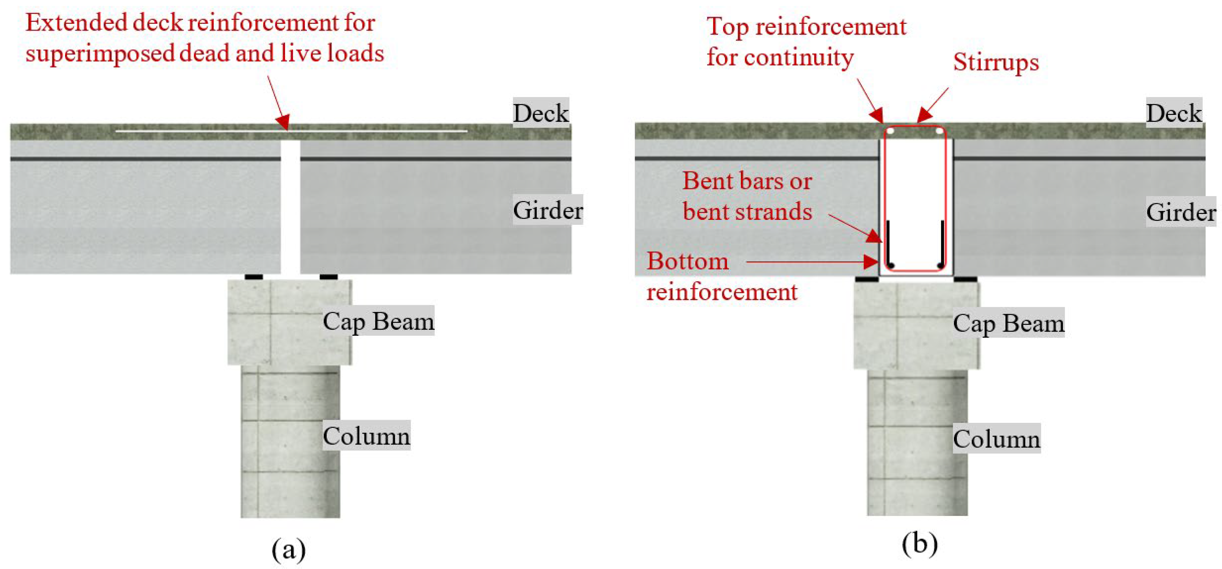
2.1. Extended Deck Reinforcement

Extended deck reinforcement, as reported by Kaar et al. (1960) [41] and Mattock and Kaar (1960) [42], presents a practical solution for achieving continuity in bridge decks. This method uses conventional deformed reinforcement to establish a strong link between two slabs, as shown in Figure 3, effectively enhancing the structure’s ability to withstand live loads. This method is common for its simplicity in construction and cost-effectiveness. However, this method has shown some limitations, as extended deck reinforcement is typically viable for spans up to a maximum of 140 feet [21]. Beyond this threshold, the efficacy of the technique diminishes, which requires alternative solutions for achieving continuity. Moreover, the application of extended deck reinforcement may induce certain challenges, due to the development of cracks at the bottom of diaphragms. This arises from the positive restraint exerted over piers, which increases creep-related effects. While this issue does not necessarily compromise the structural integrity of the bridge, it underscores the future need for through design considerations to mitigate potential long-term consequences [41,42].
In European bridge design, partial continuity is commonly achieved by using a method similar to the extended deck reinforcement approach. However, instead of relying solely on reinforcement across the deck, the reinforcement is encased within a thin concrete slab integrated into the bridge deck, as shown in Figure 3. To control stress concentrations and allow for controlled cracking, a polystyrene plate is often placed beneath the concrete encasement, weakening the section to achieve the desired structural behavior. This approach is conceptually similar to the use of expanded polystyrene (EPS) in bridge construction, where EPS is employed as a lightweight filler or formwork to optimize material usage and reduce structural weight. EPS-based solutions have been widely used in bridge decks to minimize concrete volume while maintaining structural integrity, as seen in applications such as EPS bridge deck flute fillers.

2.2. Diaphragm with Bent Bars

The utilization of diaphragms with bent bar connections represents a significant advancement in enhancing bridge deck continuity. This approach includes extending a diaphragm spanning laterally over the piers, linking the girders on either side [21], as shown in Figure 4b. This approach mitigates the occurrence of cracks in the diaphragm induced by positive moments. This is achieved by designing the diaphragm as a beam, with bottom reinforcement to withstand positive moments and negative reinforcement to ensure continuity [43]. Additionally, stirrups are employed to enhance ductility. Alternatively, horizontal bars within the diaphragm, extending through the web of the girders, can be utilized instead of stirrups. This configuration has demonstrated the ability to create a stiffer connection and improve fatigue resistance, thereby extending the bridge’s service life [22].
Despite its effectiveness in promoting continuity, studies have indicated that the weakest point in this system is the interface between the girder and the diaphragm [44]. However, this weakness does not compromise the safety of the structure but rather hinders the full achievement of the continuity effect. Furthermore, the width of the diaphragm can exceed the spacing between the girder ends, which allows for full integration. However, observations have shown instances of spalling in the diaphragm concrete when the girder end is embedded into the diaphragm [22,43,44]. One notable drawback of the method including the diaphragm with bent bar connections is its relatively higher cost compared with the extended-reinforcement method [21].

2.3. Diaphragm with Bent Strands

Diaphragms with bent strands present an alternative solution for mitigating the spalling in diaphragms observed in those with bent bar connections [22,43,44]; Figure 4b. By utilizing bent strands, stress concentration can be reduced, allowing for the embedding of girder ends into the diaphragm, thereby enabling a fully integrated connection. However, this method has exhibited larger crack widths under cyclic loads, raising concerns regarding its performance under full service and seismic conditions. Moreover, inadequate development length for the bent strands may diminish the capacity of the connection.

3. Fully Integrated Connection

Negative moments develop due to the implementation of the continuity method. Resistance against these moments is achieved through multiple mechanisms. For instance, precast girders typically include harped strands to account for negative moments in continuous applications. Additionally, in many cases, post-tensioning is applied after erection to enhance continuity, ensuring the effective redistribution of internal forces and long-term structural serviceability. Furthermore, cast-in-place diaphragms and extended deck reinforcement contribute to negative-moment resistance, improving the overall performance of the bridge.
Existing research work highlights the procedure of constructing fully integrated bridges [37,45]. Pierce (1991) [46] investigated the time-dependent effect of creep under varying load conditions. Key results include the observation of increased longitudinal deflection over time, attributed to creep, which is managed effectively through the integral design of the connection. The analysis also shows significant stress redistribution in critical sections, demonstrating that integral bridge systems experience lower peak stresses compared with conventional jointed designs. Additionally, the study highlights the maintenance advantages gained from eliminating joints, including reduced susceptibility to water ingress and structural deterioration, translating into substantial life-cycle cost savings.
To achieve the full integration of bridge joints, different continuity approaches have been developed for connecting girders to girders, girders to columns, and girders to bent cap beams. Modern applications of fully integrated precast continuous bridge decks commonly incorporate negative dowels over the piers to resist negative moments, while positive-moment segments are utilized in the main spans. These sections are typically connected by using post-tensioned cables. This section summarizes the most common and practical approaches used to establish fully integrated bridges.

3.1. Girder-to-Girder Joint

One sort of connection that can be made between two girders that are simply supported is known as a continuous joint. Typical intermediate bent detail, commonly used by the U.S. Department of Transportation [47], is shown in Figure 5. This connection enables the transfer of dead and live loads. Since the 1960s, this form of attachment has been used in the construction of PC/PS girder bridges. Continuity joints for prestressed concrete girders are constructed by using composite reinforced concrete decks and diaphragms [48]. This connection makes it possible for applied loads to pass through the structure as if it were one continuous girder, thereby enhancing the bridge’s longevity, strength, and appearance [49].
Many approaches have been proposed to establish a moment connection between superstructures. Most of these systems require the development of a connection mechanism between the girders to resist the bending moment due to the applied load. Early investigations explored the utilization of bent bars (see Figure 6a) [50,51,52]. In this configuration, hooked, mild-reinforcing bars are embedded at the end of precast girders. The hooks are then integrated into the diaphragm. Alternatively, the bent strand connection method was introduced [53,54,55], where a specified length of the prestressing strand is left protruding from the girder end upon de-tensioning. The strand is then bent into a 90-degree hook and embedded within the diaphragm (see Figure 6b). The use of bent strands in continuity connections requires careful consideration of bending radii to prevent excessive stress concentrations in the seven-wire prestressing strands. Large bending radii are typically needed to avoid premature damage or loss of prestress, ensuring the strands maintain their intended tensile capacity. Additionally, when strands are bent at angles exceeding 90°, an unequal distribution of strand forces can occur, leading to localized stress variations that may affect the structural performance of the connection. Additional approaches to positive-moment connections include the use of straight bars and welded bars, the adoption of mechanical strand connectors, and the implementation of partial diaphragms to pre-compress the section [53,56,57,58].
The performance of bent bars and bent strands was studied in Newhouse (2005) [23]. Both connections were subjected to identical loading conditions. The study recommended using the connection with extended bent bars in typical design scenarios, as it was able to resist moments well beyond the design cracking moment in a cracked state, remained stiffer than the connection with extended strands throughout cyclic testing, and displayed sufficient strength for the designed ultimate positive moment. It is also recommended to follow the provisions of NCHRP report 519 [22] when detailing the embedment lengths of the bars, ensuring that the bars extend well into the prestressed portion of the girder.

3.2. Girder-to-Column Joint

Pang et al. (2008, 2010) [59,60] introduced an innovative girder-to-column connection method designed to speed up the construction of bridge bents in regions prone to seismic activity. This system comprises a precast column and a precast cap beam, joined on site by using large bars positioned inside corrugated metal ducts, as illustrated in Figure 7. The precast column features six reinforcing bars protruding vertically from the top of the column. Through a series of experiments, it was found that the force–deformation response and damage progression of these precast connections were comparable to those of cast-in-place connections. However, it was observed that the resistance started to decline at a drift ratio of 5%, corresponding to the beginning of bar buckling and fracture. Furthermore, the distribution of deformations differed significantly between the precast columns and the cast-in-place one, with 90% of the flexural deformations in the precast system being concentrated at one large crack at the beam–column interface, while the deformations in the cast-in-place connection were more uniformly distributed up the column.

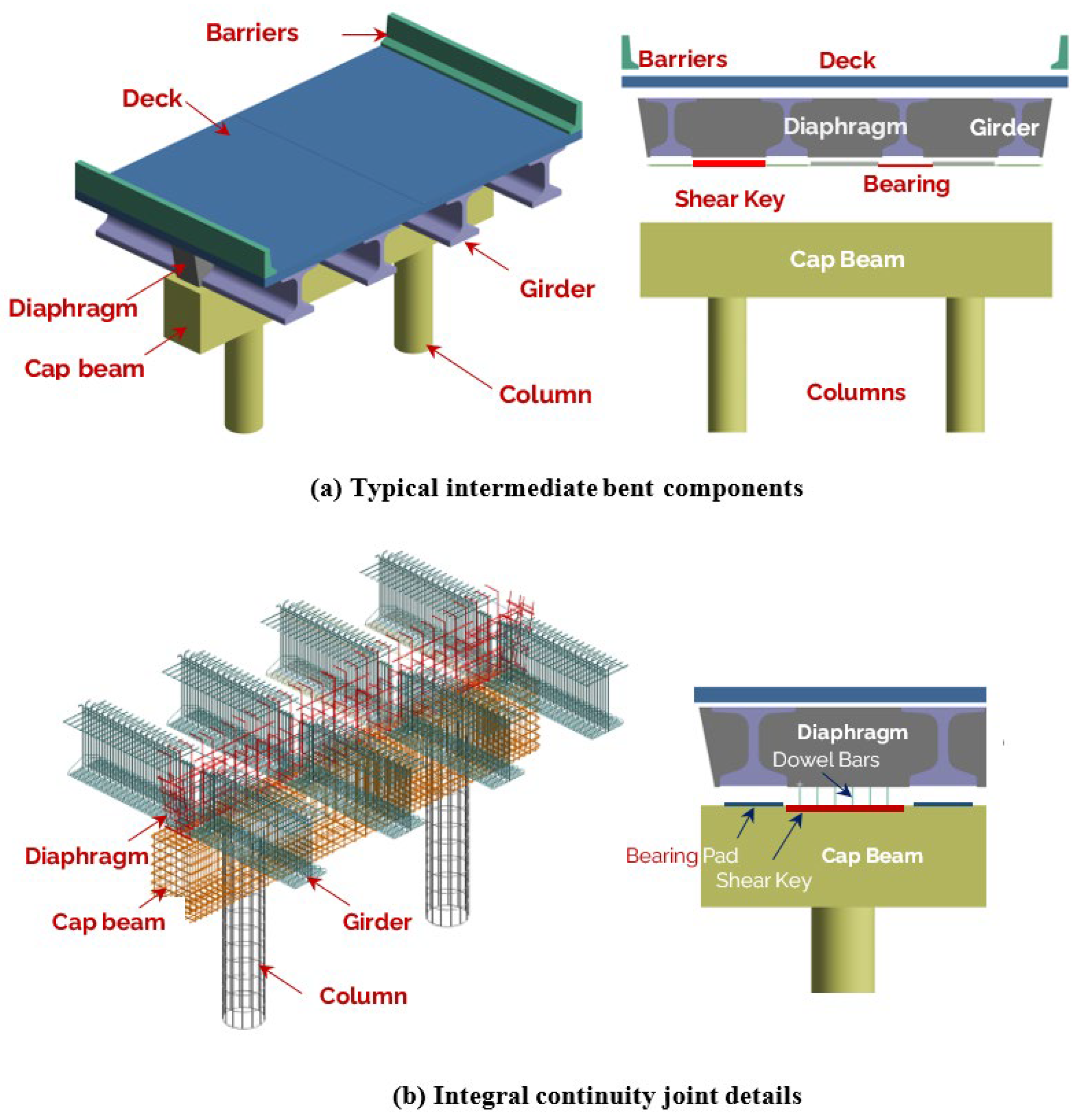
3.3. Girder-to-Bent Cap Beam Joint

Peggar et al. (2014) [35] introduced two innovative designs for connecting precast bulb tee girders to bridge caps, employing extended prestressing strands. These connections were designed to withstand the positive moments induced by seismic forces at the girder-to-cap joint, thus mitigating the risk of damage or collapse. The first design featured curved extended strands that relied on bond strength for anchorage, while the second one utilized spliced strands with anchor plates and chucks. Both designs also incorporated grouted dowel bars placed through the girder web.

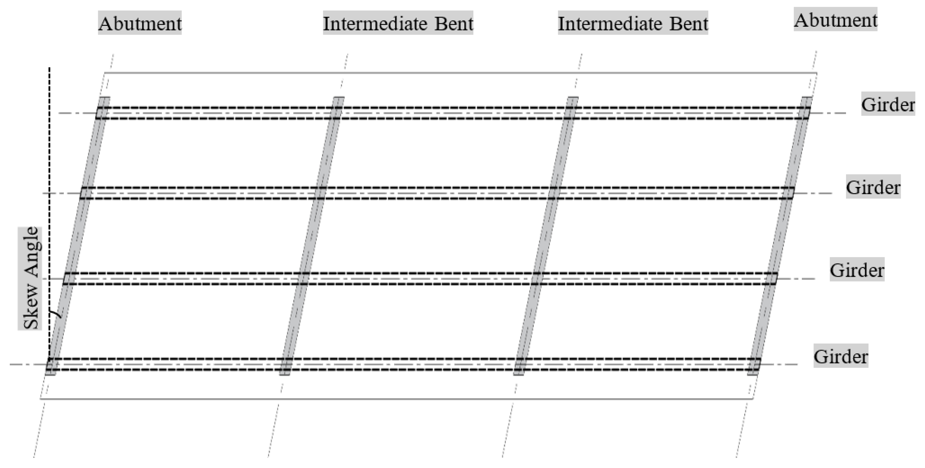
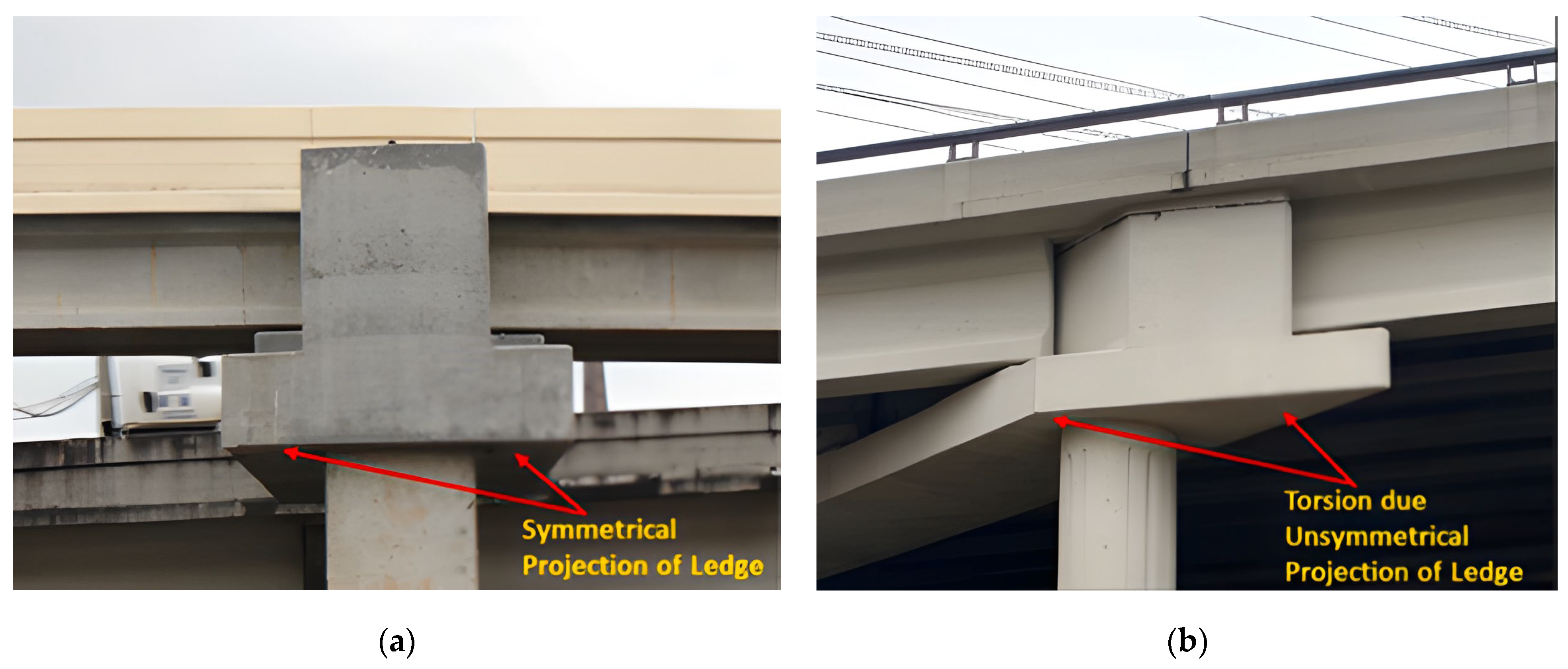
3.4. Skewed Connections in Inverted-T Bent Caps

In a skewed bridge, intermediate bents, including the cap beam, are positioned at a horizontal angle with the superstructure, as shown in Figure 8. A common example is the skewed inverted-T bent caps (ITBCs), as shown in Figure 9, which act as structural beams with loads concentrated at their lower edges. Unlike standard top-loaded beam structures, the transfer of force in skewed ITBCs follows a different process. Initially, loads transmit from the ledge to the web in a transverse direction via vertical supports. Subsequently, these loads are conveyed into the web and reach the supports longitudinally [61]. However, this process can pose complex issues, such as a combination of flexural, shear, and torsional loads, leading to cracking due to unequal load distribution on the angled lower ledge.
Experimental studies have been conducted on ITBC connections with diaphragms. Saber et al. (2011) [62] investigated the use of continuity diaphragms on skewed bents in PS/PC girder bridges and found them to pose challenges in detailing and construction, especially as skew angles decrease or girder spacing narrows. Additionally, their effectiveness at high skew angles was questioned. Oz et al. (2022) [63] suggested that adding end reinforcement to skewed ITBCs reduces crack width under service load by over 15% and that increasing concrete strength enhances service load stiffness and ultimate capacity. Further research by Roy et al. (2021) [61] evaluated ITBCs with varying skew angles. The study recommended aligning all shear and hanger stirrups with the ITBCs’ skew angle and maintaining specific distances between transverse reinforcements to minimize diagonal fractures and stress concentration. El-Ariss et al. (2021) [64] concluded that the behavior of inverted-T beams with fixed web height remained unaffected when varying the skew angle, suggesting potential weight reduction without compromising strength or flexibility.
In summary, skewed ITBCs offer unique advantages in bridge construction, particularly in their ability to efficiently transfer loads while minimizing structural weight. However, their utilization poses challenges in design, construction, and performance, especially regarding detailing, construction difficulties, and their effectiveness at high skew angles. Despite these challenges, ongoing research efforts have identified promising strategies to enhance their performance, including the implementation of end reinforcement, the optimization of concrete strength, and the alignment of stirrups with the skew angle.

4. Advanced Connecting Approaches

4.1. Ultra-High-Performance Concrete (UHPC)

One area of research that has been explored is the use of UHPC in conjunction joints. UHPC is used in girder-to-girder connections, girder-to-deck interfaces, and girder-to-column joints to improve load transfer, reduce cracking, enhance durability, and increase resistance to seismic activity [32]. Construction joints in this context refer to the predefined discontinuities where successive concrete pours meet, often occurring at interfaces between precast and cast-in-place concrete elements. UHPC can be used to create a monolithic connection between precast elements, which eliminates the need for traditional mechanical fasteners. Additionally, the high compressive strength of UHPC allows for thinner joint sections, reducing the overall weight of the structure [65].
William et al. (2019) [48] proposed utilizing UHPC as a potential solution for mitigating cracking in continuity joints within bridges. Six specimens were constructed and evaluated, each comprising two precast girders connected by a UHPC joint. Three of the specimens followed the AASHTO LRFD (2014) requirements, focusing on continuity joint detailing for new-bridge construction, while the remaining three specimens addressed continuity joint detailing for retrofitting existing bridges. The reinforcement ratios were consistent across both designs. A static point load was applied at the midpoint of the span to induce the highest negative moment in the continuity joint. Additionally, a positive-moment test was conducted on the third specimen of each joint type. The test results indicated that the utilization of UHPC enhanced the girder capacity beyond design values, allowing higher negative moments to be carried with similar crack development observed in both joint types and limited flexural cracking within the joint. Interestingly, failure was more likely to occur in the girders rather than the joints. Retrofitted specimens exhibited superior performance compared with originally built specimens, showing greater ultimate capacity and reduced deflection.
Optimizing the design of precast prestressed girder bridges is crucial to enhancing sustainability in modern infrastructure. The incorporation of UHPC significantly improves the durability and lifespan of these structures, reducing long-term maintenance and material replacement needs. UHPC’s superior strength and resistance to environmental deterioration help lower life-cycle environmental impacts by minimizing resource consumption and decreasing carbon emissions associated with frequent repairs and reconstruction [7].
While UHPC provides exceptional strength, durability, and bond performance, its application in bridge construction comes with certain limitations. The high material cost and specialized production requirements can restrict its use in large-scale projects [66,67]. Additionally, some UHPC mixes require special curing techniques to achieve optimal performance, often necessitating heat curing and specialized equipment. Workability challenges also arise due to its low fluidity, making proper placement and compaction critical, particularly in narrow connection joints [66,67,68,69]. Furthermore, the stiffness difference between UHPC and conventional concrete can lead to compatibility issues, requiring careful interface detailing to prevent premature cracking. Despite these challenges, UHPC remains a promising solution for improving structural performance in precast girder bridge continuity.

4.2. Unstressed Strands

Liang et al. (2021) [70] conducted an experimental and analytical study to investigate the use of unstressed strands as connection reinforcement for precast concrete members to establish positive-moment connections for seismic applications. The study considered the use of unstressed strands that extended from the ends of precast concrete members or were placed within grouted ducts. The findings revealed that applying initial stress to strands embedded in grouted ducts compromised the bond capacity between the strand and the surrounding grout. Moreover, the study highlighted the advantageous role of tendon curvature in fully developing the strand embedded within grouted ducts and concrete. The use of unstressed strands in continuous precast girder applications presents a promising alternative for enhanced structural adaptability. However, the efficiency of encasing these strands in grouted ducts remains a subject of discussion, as adequate elongation before activation may be difficult to achieve. Further research is needed to evaluate the long-term effectiveness and practical implementation of these methods in different structural applications.

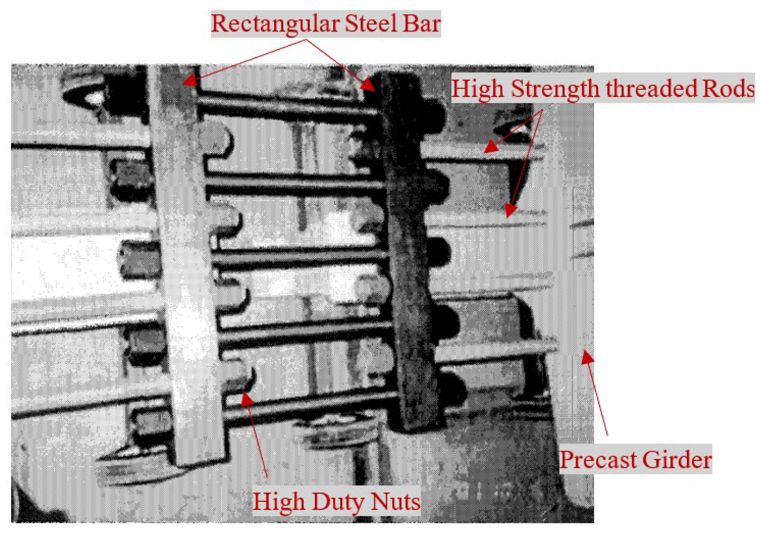
4.3. Mechanical Splices

An innovative threaded rod continuity system was introduced for precast concrete I-girders by [71,72]. This continuity detail employed high-strength threaded bars embedded in the top flange of the girder and connected by using steel blocks and nuts. Following the casting of the continuity diaphragm, the bolts were tightened into position. The system’s key advantage lies in its ability to establish continuity not only for live loads and superimposed dead loads but also for the dead load of the slab itself. This additional continuity has the potential to reduce the number of strands required in the girders, thereby enhancing efficiency. Furthermore, this connection method was highlighted for its relative simplicity in construction. Building upon this method, Sun (2004) [73] investigated a threaded rod system utilizing high-strength bars in line and cross-connecting them with high-strength threaded rods, Figure 10. A significant advantage of this system is the precasting of the high-strength bars before the deck slab is installed, ensuring they experience permanent negative moment at the support upon deck loading. This precasting process effectively mitigates the potential for cracking in the bottom flange of the girders induced by positive thermal gradient effects.
Cheng (2015) [74] suggested the Extend Strand with a Mechanical Splice (ESMS) and the Extended Strand with a Lap Splice (ESLS) connections for the connection between precast bulb tee girders and cast-in-place bent caps, as shown in Figure 11. These connections include deck reinforcement, unstressed strands extending from the precast girder, and dowel bars grouted into the girder’s web. These connections were evaluated experimentally, and the findings indicated that both connections had sufficient ability to establish a moment-resisting connection between the girders and the bending cap under the specified seismic loads. The test findings also indicated that concrete crushing at the bottom of the girder-to-cap contact weakened the connection’s strength under negative moments beyond the desired value. Positive-moment resistance was given by the shear friction behavior at the interface between the precast girder and the cast-in-place diaphragm poured around the girder. The success in testing the seismic performance of the ESMS and ESLS connections indicates that both connections are sufficient to build a moment-resistant connection for precast bulb-tee girders subjected to vertical and lateral loads and may be used in regular bridge designs.

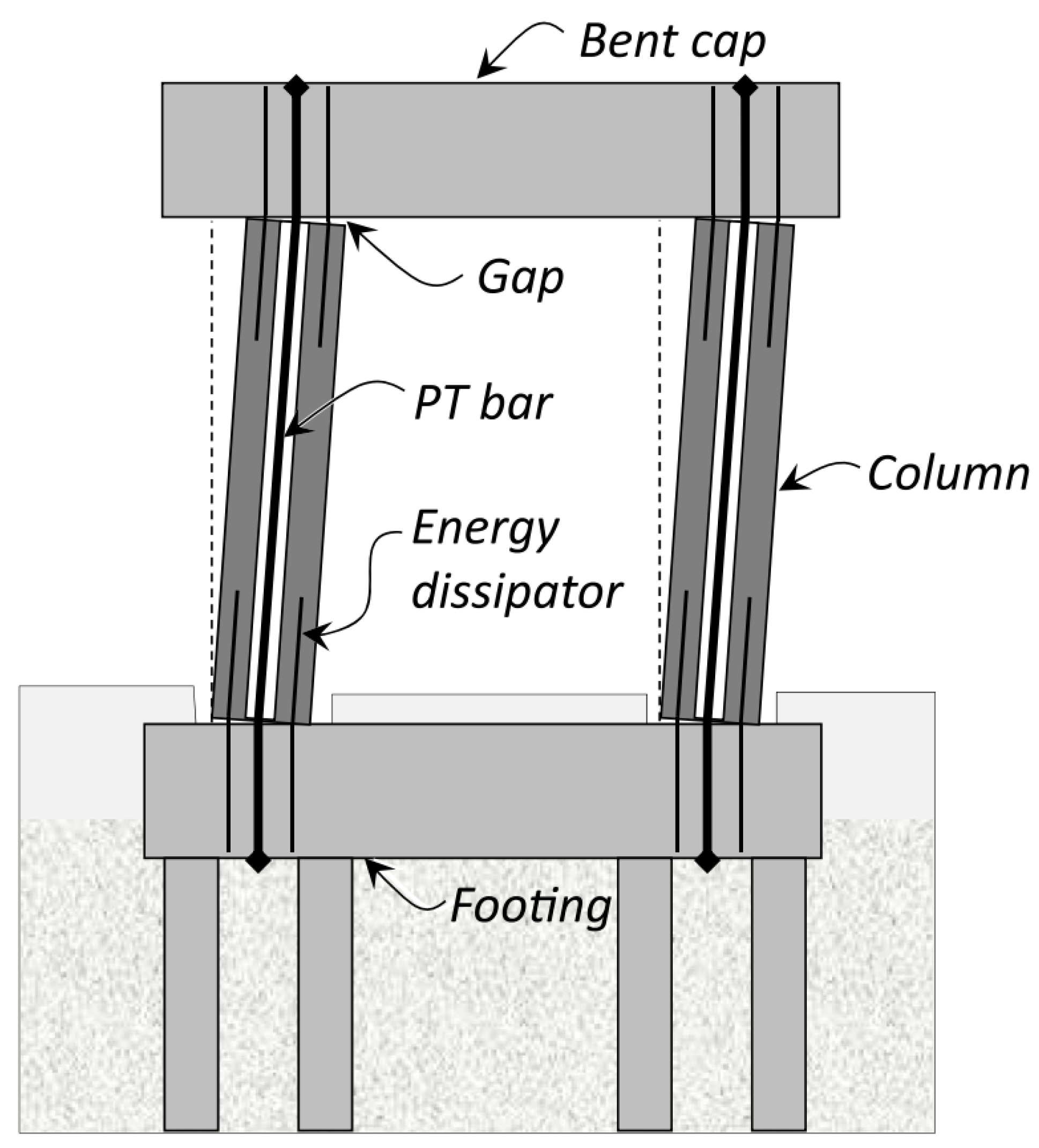
5. Seismic Performance

While limited research has been performed to investigate the structural performance of bent connections in PC/PS girder bridges, the majority of existing studies have primarily centered on the seismic response. Joint construction for seismic systems can be categorized into two main types: emulative and jointed constructions [75]. In emulative construction, connections are designed and function as equivalent cast-in-place monolithic reinforced concrete [75,76,77]. These connections can be either ductile or strong. Ductile connections are designed to undergo flexural yielding, forming ductile plastic hinges across precast member-to-member joints. Conversely, structures with strong connections are designed to experience flexural yielding within the precast members at predetermined and properly detailed locations adjacent to or away from the joints. On the other hand, jointed constructions utilize precast connection approaches, such as employing unbonded post-tensioning steel [78,79,80]. In this approach, nonlinear rotations of the structure are deliberately concentrated at the ends of the precast members within the joint regions, achieved through controlled rocking at the joint interface [81,82]. This deliberate concentration of rotations aims to avoid significant inelastic behavior or damage within the members.
The development of comprehensive code provisions for incorporating precast concrete in seismic bridge design remains incomplete. This gap in code provisions can be attributed to the historically limited utilization of precast concrete in seismic bridge design. In particular, the adoption of precast girders in bridge construction has been delayed by two key design considerations: Firstly, concerns have arisen regarding the reliable establishment of positive-moment connections between precast girders and bent cap beams, leading to uncertainties about allowing for the formation of a plastic hinge at the top of columns or piers [82,83]. Secondly, the necessity for a connection involving mild steel reinforcement between the cap beam and girders has been mandated to ensure adequate shear transfer across the cap beam-to-girder joint in scenarios where vertical acceleration exceeds 0.25 g [82,84]. These gaps in code provisions motivate research to perform more investigation into connections in PC/PS girder bridges under seismic loads.
The seismic performance of PC/PS girder bridges primarily relies on the connections between the different precast structural components. Current seismic design aims to induce inelastic behavior at column or pier ends, reducing damage to the superstructure and foundation and facilitating inspection and repair processes. Consequently, much research has concentrated on connections at these critical joints, column–foundation and column–cap connections. Typically, columns are precast to their full height and linked to adjacent members through unbonded post-tensioning, as shown in Figure 12. Various approaches have been developed to enhance column performance under seismic conditions, as summarized in Table 1.
Superstructures, which include bent cap beams, girders, and deck components, are designed to withstand overstrength moment resistance while maintaining linear–elastic behavior. Limited research has been performed on the seismic response of connections within precast bridge superstructures. For instance, Werff et al. (2015) [83] documented the response of two distinct precast I-girder-to-cap beam connections. Additionally, the joints between superstructure segments and those between the superstructure and columns have been subjects of investigation. Burnell et al. (2004) [85] conducted quasi-static testing on these joints, while Sideris et al. (2015) [86,87] subjected them to multiaxial shake table excitation. Snyder et al. (2011) [88] investigated the seismic response and overall moment capacity of connections between precast I-girders and inverted-T bent cap bridges. The design guidelines by that time presumed that these connections would weaken under seismic conditions, necessitating their design as pinned connections. Consequently, precast girder options for seismic bridges were deemed inefficient. However, the research study revealed that the I-girder to inverted-T bent cap bridge connection could function as a fully continuous connection for both positive and negative moments under both gravity and seismic loads. This finding contradicted the design assumptions outlined in Caltrans’ Seismic Design Criteria at the time. Peggar et al. (2014) [35] investigated the connection between precast bulb tee girders and bridge caps. The study explored the use of curved extended strands, relying on bond strength for anchorage, as well as spliced strands with anchor plates and chucks. The results demonstrated that both connections could resist seismic forces in accordance with current design standards. The connections’ design can be improved by adding stirrups under the top flange of the girders to prevent the spalling of the cap cover concrete.
The durability of bridges, particularly in seismic regions, is another concern, as material degradation and cumulative damage over time can significantly impact structural performance. Aging infrastructure may exhibit reduced seismic resilience due to factors such as the corrosion of reinforcement, concrete cracking, and spalling [88]. Given that continuous joints play a crucial role in the overall seismic resistance of bridges, their long-term durability must be carefully considered to prevent premature deterioration, ensure effective load transfer, and maintain structural integrity under seismic loading.
Figure 12. Typical seismic design of a bridge bent using unbonded post tensioned columns (reprinted from [89]).
Civileng 06 00016 g012
Table 1. Approaches to improving the structural performance of column ends under seismic loads.
ReferenceLocationApproach
Mander et al. (1997) [90]Column–foundationInvestigated steel plates at the joint.
Billington et al. (2004) [91]Column–foundationSubstituted column ends with fiber-reinforced concrete shells, either hollow or filled with self-consolidating concrete.
Palermo et al. (2007) [92]Column–foundationImplemented steel plates at the foundation top, armored column toes with steel angles, and linked a hemispherical steel block to guarantee shear transfer.
Marriot et al. (2009, 2011)
[93,94]
Column–foundationInvestigated replaceable external hysteretic dampers.
ElGawady et al. (2010) [95]Column–foundationImplemented thin neoprene pads at column ends, resulting in reduced lateral stiffness of the column.
Trono et al. (2014) [96]Column–foundationResearched various bedding mortars for the joint between column and cap beam and replaced column ends with fiber-reinforced concrete shells.
Motaref et al. (2014) [97]Column–foundationUtilized laminated elastomeric bearings at column ends, resulting in changes in the dynamic characteristics of the column.
Tazarv et al. (2015) [98]Column–foundationReplaced column ends with fiber-reinforced concrete shells, either hollow or filled with self-consolidating concrete.
Mashal et al. (2015), White et al. (2016) [99,100]Column–foundationExplored unbonded PT bridge columns embedded in foundation sockets, strengthened with a steel jacket.
Thonstad et al. (2016) [101]Column–foundationEmployed partially debonded mild-reinforcing or stainless-steel reinforcing bars for energy dissipation in jointed bridge columns.
Tobolski et al. (2008) [102]Column–capInvestigated the types of bedding mortar that can withstand the impact and transfer shear at the joint between the column and the cap beam.
Cohagen et al. (2008) [103]Column–capInvestigated various bedding mortar types for the joint between column and cap beam and utilized spirals to confine column ends.
Restrepo et al. (2011) [104]Column–capExplored different bedding mortars for the joint between column and cap beam and studied columns with dual steel shells (concrete cast between shells).
Guerrini et al. (2013) [105]Column–capInvestigated bedding mortars for the joint between column and cap beam and employed headed reinforcing bars at column ends for compression transfer.
Guerrini et al. (2014) [89]Column–capExamined bedding mortars for the joint between column and cap beam, investigated columns with dual steel shells (concrete cast between shells), and used headed reinforcing bars at column ends for compression transfer.
Eberhard et al. (2014) [106]Column endsDemonstrated the feasibility of precast pretensioned bridge columns with partially debonded strands, employing a hybrid fiber-reinforced concrete shell for confinement at the critical column ends.

6. Conclusions

This paper offers a comprehensive review of previous research efforts focusing on the development and performance of both partial (involving a continuous deck cast over supports while allowing adjacent girders to have some movement relative to each other) and fully integrated continuous bridges. It also highlights research efforts to improve seismic resilience and integrate advanced technologies for enhancing bridge construction practices. Based on this review, the following conclusions can be drawn:
  • Extended deck reinforcement offers a simple and cost-effective solution for achieving partially integrated continuity in bridge decks but may have limitations for large spans and can induce challenges such as the development of cracks at the bottom of diaphragms.
  • Diaphragms with bent bar connections mitigate the occurrence of cracks induced by positive moments, but weaknesses at the girder–diaphragm interface prevent the full achievement of continuity effects and may lead to spalling in the diaphragm concrete.
  • Diaphragms with bent strands offer an alternative solution for mitigating spalling in diaphragms observed in those with bent bar connections, but there are concerns that crack widths under cyclic loads and inadequate development length for the bent strands may affect performance under full service and seismic conditions.
  • Positive-moment connections between superstructures often involve bent bars or bent strands, with bent bars demonstrating superior performance in typical design scenarios.
  • While continuity diaphragms may improve load distribution properties, their effectiveness in skewed continuous bridges is limited.
  • Ultra-High-Performance Concrete (UHPC) offers several benefits for joint connections, including increased load capacity, improved durability, and enhanced resistance to seismic activity.
  • Mechanical splices, such as the threaded rod continuity system, offer advantages in establishing continuity for live loads, superimposed dead loads, and the dead load of the slab itself.
  • The seismic performance of PC/PS girder bridges relies heavily on the connections between precast structural components, particularly at critical joints like column–foundation and column–cap connections.
  • Research efforts have focused on investigating the structural performance of column ends under seismic loads, including the use of steel plates, fiber-reinforced concrete shells, steel jackets, spirals, headed reinforcing bars, and unbonded post-tensioning, to improve shear transfer and compression transfer at column–foundation and column–cap joints.
  • While this study provides a comprehensive review of continuous joints in precast prestressed girder bridges, several aspects require further research. The seismic performance of continuous joints needs additional experimental and numerical investigations to enhance resilience in highly seismic regions. Moreover, the long-term durability of these connections under environmental exposure, fatigue, and corrosion remains a critical area of study. The use of post-tensioned concrete columns in continuous bridge systems is still not widely explored, and further studies are needed to evaluate their structural feasibility and force transfer mechanisms. Additionally, future research should focus on innovative connection methods, including modular precast solutions, hybrid joints, and advanced materials, to improve constructability and performance. The integration of smart monitoring technologies and AI-based structural health assessment could further enhance the reliability and maintenance of continuous bridges.

Funding

This research received no external funding.

Data Availability Statement

The original contributions presented in this study are included in the article. Further inquiries can be directed to the corresponding author.

Conflicts of Interest

The authors declare no conflict of interest.

References

  1. Tomek, R. Advantageous bridge construction with prefabrication. In Proceedings of the Creative Construction Conference, Ljubljana, Slovenia, 30 June–3 July 2018; pp. 271–275. [Google Scholar]
  2. Ussenkulov, Z.A.; Shukeyeva, S.S.; Ussenkulova, S.Z. Advantage Use of Precast Concrete for Bridges. In Proceedings of the Industrial Technologies and Engineering (ICITE-2018), Singapore, 3–5 September 2018; pp. 232–236. [Google Scholar]
  3. Tomek, R. Advantages of precast concrete in highway infrastructure construction. Procedia Eng. 2017, 196, 176–180. [Google Scholar]
  4. Faraji, S.; Ting, J.M.; Crovo, D.S.; Ernst, H. Nonlinear analysis of integral bridges: Finite-element model. J. Geotech. Geoenviron. Eng. 2001, 127, 454–461. [Google Scholar]
  5. Greimann, L.F.; Yang, P.-S.; Wolde-Tinsae, A.M. Nonlinear analysis of integral abutment bridges. J. Struct. Eng. 1986, 112, 2263–2280. [Google Scholar]
  6. Okeil, A.M.; Cai, S.; Chebole, V.; Hossain, T. Evaluation of Continuity Detail for Precast Prestressed Girders; Louisiana Transportation Research Center: Baton Rouge, LA, USA, 2011. [Google Scholar]
  7. Pacheco, P.; Adão da Fonseca, A.P.; Resende, A.; Campos, R. Sustainability in bridge construction processes. Clean Technol. Environ. Policy 2010, 12, 75–82. [Google Scholar] [CrossRef]
  8. Pierrehumbert, R. There is no Plan B for dealing with the climate crisis. Bull. At. Sci. 2019, 75, 215–221. [Google Scholar] [CrossRef]
  9. Cao, J.; Wang, C.; Gonzalez-Libreros, J.; Wang, T.; Tu, Y.; Elfgren, L.; Sas, G. Extended applications of molecular dynamics methods in multiscale studies of concrete composites: A review. Case Stud. Constr. Mater. 2025, 22, e04153. [Google Scholar] [CrossRef]
  10. Burns, N.H. Development of continuity between precast prestressed concrete beams. PCI J. 1966, 11, 23–36. [Google Scholar]
  11. Thippeswamy, H.K.; GangaRao, H.V.S.; Franco, J.M. Performance evaluation of jointless bridges. J. Bridge Eng. 2002, 7, 276–289. [Google Scholar]
  12. Hosteng, T.K.; Phares, B.M. Economic Impact of Multi-Span, Prestressed Concrete Girder Bridges Designed as Simple Span Versus Continuous Span: Tech Transfer Summary; Midwest Transportation Center: Ames, IA, USA, 2016. [Google Scholar]
  13. Okeil, A.M.; ElSafty, A. Partial continuity in bridge girders with jointless decks. Pract. Period. Struct. Des. Constr. 2005, 10, 229–238. [Google Scholar]
  14. Al-Ani, M.; Murashev, A.; Palermo, A.; Andisheh, K.; Wood, J.; Goodall, D.; Lloyd, N. Criteria and guidance for the design of integral bridges. Proc. Inst. Civ. Eng. Bridge Eng. 2018, 171, 143–154. [Google Scholar]
  15. Gharad, A.M.; Sonparote, R.S. Influence of soil-structure interaction on the dynamic response of continuous and integral bridge subjected to moving loads. Int. J. Rail Transp. 2020, 8, 285–306. [Google Scholar] [CrossRef]
  16. Kim, S.-H.; Yoon, J.-H.; Kim, J.-H.; Choi, W.-J.; Ahn, J.-H. Structural details of steel girder–abutment joints in integral bridges: An experimental study. J. Constr. Steel Res. 2012, 70, 190–212. [Google Scholar] [CrossRef]
  17. Hulangamuwa, C.; Abeykoon, D. Behaviour of Jointless Bridge Decks with Link Slabs: A Review. In Proceedings of the International Conference of Structural Engineering & Construction Management (ICSECM-2019), Kandy, Sri Lanka, 12–14 December 2020. [Google Scholar]
  18. Loveall, C.L. Jointless bridge decks. Civ. Eng. 1985, 55, 64–67. [Google Scholar]
  19. Burke, M.P., Jr. Semi-integral bridges: Movements and forces. Transp. Res. Rec. 1994, 1460, 1–7. [Google Scholar]
  20. Burke, M.P., Jr. Integral bridges: Attributes and limitations. Transp. Res. Rec. 1993, 1393, 1–8. [Google Scholar]
  21. Oesterle, R.G.; Glikin, J.D.; Larson, S.C. Design of Precast, Prestressed Bridge Girders Made Continuous; Transportation Research Board: Washington, DC, USA, 1989. [Google Scholar]
  22. Miller, R.A. Connection of Simple-Span Precast Concrete Girders for Continuity; Transportation Research Board: Washington, DC, USA, 2004. [Google Scholar]
  23. Newhouse, C.D. Design and Behavior of Precast, Prestressed Girders Made Continuous: An Analytical and Experimental Study. Ph.D. Thesis, Virginia Polytechnic Institute and State University, Blacksburg, VA, USA, 2005. [Google Scholar]
  24. Saber, A.; Toups, J.; Guice, L.; Tayebi, A. Continuity Diaphragm for Skewed Continuous Span Precast Prestressed Concrete Girder Bridges; Louisiana Transportation Research Center: Baton Rouge, LA, USA, 2004. [Google Scholar]
  25. Saber, A.; Mothukuri, A.K.; Arasangi, P. Field Verification for the Effectiveness of Continuity Diaphragms for Skewed Continuous P/CP/S Concrete Girder Bridges; Louisiana Transportation Research Center: Baton Rouge, LA, USA, 2009. [Google Scholar]
  26. Naseri, H.; Jahanbakhsh, H.; Foomajd, A.; Galustanian, N.; Karimi, M.M.; DWaygood, E.O. A newly developed hybrid method on pavement maintenance and rehabilitation optimization applying Whale Optimization Algorithm and random forest regression. Int. J. Pavement Eng. 2023, 24, 2147672. [Google Scholar]
  27. Kwon, O.S.; Kim, E.; Orton, S. Calibration of live-load factor in LRFD bridge design specifications based on state-specific traffic environments. J. Bridge Eng. 2011, 16, 812–819. [Google Scholar]
  28. El-Sisi, A.; Hassanin, A.; Alsharari, F.; Galustanian, N.; Salim, H. Failure behavior of composite bolted joints. CivilEng 2022, 3, 1061–1076. [Google Scholar] [CrossRef]
  29. Galustanian, N.; El-Sisi, A.; Amer, A.; Elshamy, E.; Hassan, H. Review of the Structural Performance of Beams and Beam–Column Joints with Openings. CivilEng 2023, 4, 1233–1242. [Google Scholar] [CrossRef]
  30. Floyd, R.W.; Jeffery Volz, P.S.; Funderburg, C.K.; Amy McDaniel, M.S.; Trevor Looney, M.; Candidate Jake Choate, P.; Stephen Roswurm, C.; Connor Casey, C.; Raina Coleman, M.; Maranda Leggs, M.; et al. Evaluation of Ultra-High-Performance Concrete for Use in Bridge Connections and Repair; Oklahoma Department of Transportation: Oklahoma City, OK, USA, 2020.
  31. Bazaez, R.; Dusicka, P. Cyclic behavior of reinforced concrete bridge bent retrofitted with buckling restrained braces. Eng. Struct. 2016, 119, 34–48. [Google Scholar] [CrossRef]
  32. Aboukifa, M.; Moustafa, M.A.; Saiidi, M.S. Seismic response of precast bridge columns with composite non-proprietary UHPC filled ducts ABC connections. Compos. Struct. 2021, 274, 114376. [Google Scholar] [CrossRef]
  33. Saingam, P.; Sutcu, F.; Terazawa, Y.; Fujishita, K.; Lin, P.C.; Celik, O.C.; Takeuchi, T. Composite behavior in RC buildings retrofitted using buckling-restrained braces with elastic steel frames. Eng. Struct. 2020, 219, 110896. [Google Scholar] [CrossRef]
  34. Wang, W.W.; Dai, J.G.; Huang, C.K.; Bao, Q.H. Strengthening multiple span simply-supported girder bridges using post-tensioned negative moment connection technique. Eng. Struct. 2011, 33, 663–673. [Google Scholar] [CrossRef]
  35. Peggar, R. Two Integral Girder Connections for Precast Concrete Bridges in Seismic Regions Utilizing Extended Prestressing Strands. Master’s Thesis, Iowa State University, Ames, IA, USA, 2014. [Google Scholar]
  36. Holombo, J.; Priestly, M.J.N.; Seible, F. Continuity of precast prestressed spliced-girder bridges under seismic loads. PCI J. 2000, 45, 40–63. [Google Scholar]
  37. Hambly, E.C. Integral Bridges. Proc. Inst. Civ. Eng. Transp. 1997, 123, 30–38. [Google Scholar] [CrossRef]
  38. Caner, A. Behavior and design of link slabs for jointless bridge decks. PCI J. 1998, 43, 68–81. [Google Scholar]
  39. Burke, M.P. Design of integral concrete bridges. Concr. Int. 1993, 15, 37–42. [Google Scholar]
  40. Siros, K.A.; Spyrakos, C.C. Creep analysis of hybrid integral bridges. Transp. Res. Rec. 1995, 1476, 147–154. [Google Scholar]
  41. Kaar, P.H.; Kriz, L.B.; Hognestad, E. Precast-Prestressed Concrete Bridges: 1. Pilot Tests of Continuous Girders; Research and Development Laboratories, Portland Cement Association: Washington, DC, USA, 1960. [Google Scholar]
  42. Mattock, A.H.; Kaar, P.H. Precast-Prestressed Concrete Bridges 3: Further Tests of Continuous Girders; Research and Development Laboratories, Portland Cement Association: Washington, DC, USA, 1960. [Google Scholar]
  43. Mirmiran, A.; Kulkarni, S.; Miller, I.; Hastak, M.; Castrodale, I. Positive moment cracking in diaphragms of simple-span prestressed girders made continuous. Spec. Publ. 2001, 204, 117–134. [Google Scholar]
  44. Miller, R.A.; Castrodale, R.; Mirmiran, A.; Hastak, M.; Baseheart, T.M. Connections Between Simply Supported Concrete Beam Made Continuous. In Proceedings of the 2004 Concrete Bridge Conference Federal Highway, Charlotte, NC, USA, 17–18 May 2004. [Google Scholar]
  45. Demartini, C.J.; Heywood, R.J. Repair of the southern approach to the story bridge by elimination of the contraction joints. In Bridges: Part of the Transport System. Proceedings of the AUSTROADS Bridges Conference AUSTROADS; Queensland University of Technology: Brisbane, QLD, Australia; Queensland Department of Transport: Brisbane, QLD, Australia; Australian Road Research Board: Melbourne, VIC, Australia, 1991. [Google Scholar]
  46. Pierce, P. Jointless redecking. Civ. Eng. 1991, 61, 60–61. [Google Scholar]
  47. Missouri Department of Transportation. Engineering Policy Guide 751.31; Missouri Department of Transportation: Jefferson City, MO, USA, 2023.
  48. William, C.; Norman, C. Ultra-High Performance Concrete for Connections of Precast, Prestressed Girders Made Continuous for Live Load. Master’s Thesis, The University of Oklahoma, Norman, OK, USA, 2019. [Google Scholar]
  49. Freyermuth, C.L. Design of Continuous Highway Bridges with Precast, Prestressed Concrete Girders. PCI J. 1969, 14, 14–39. [Google Scholar] [CrossRef]
  50. Hanson, N.W. Precast-Prestressed Concrete Bridges: 2. Horizontal Shear Connections; Research and Development Laboratories, Portland Cement Association: Washington, DC, USA, 1960. [Google Scholar]
  51. Mattock, A.H. Precast-Prestressed Concrete Bridges. J. PCA Res. Dev. Lab. 1961, 6, 42–56. [Google Scholar]
  52. Galustanian, N.; Elshazli, M.T.; Elsisi, A.; Orton, S.L. Evaluating Rotational Restraint in Non-Integral Intermediate Bents with Closed Diaphragms. Available online: https://papers.ssrn.com/sol3/papers.cfm?abstract_id=5169243 (accessed on 4 March 2025).
  53. Abdalla, O.A.; Ramirez, J.A.; Lee, R.H. Strand Debonding in Pretensioned Beams-Precast Prestressed Concrete Bridge Girders with Debonded Strands-Continuity Issues; Purdue University: West Lafayette, IN, USA, 1993. [Google Scholar]
  54. Clark, L.A.; Sugie, I. Serviceabiilty Limit State Aspects of Continuous Bridges Using Precast Concrete Beams. Struct. Eng. 1997, 75, 185–190. [Google Scholar]
  55. Salmons, J.R. End Connections of Pretensioned I-Beam Bridges; Federal Highway Administration: Washington, DC, USA, 1974.
  56. Thonstad, T.; Eberhard, M.O.; Stanton, J.F. Design of prestressed, jointed columns for enhanced seismic performance. Structures 2021, 33, 1007–1019. [Google Scholar] [CrossRef]
  57. Snyder, R.M. Seismic Performance of an I-Girder to Inverted-T Bent Cap Bridge Connection; Iowa State University: Ames, IA, USA, 2010. [Google Scholar]
  58. Tadros, M.K.; Ficenec, J.A.; Einea, A.; Holdsworth, S. A new technique to create continuity in prestressed concrete members. PRECAST/PRESTRESSED Concr. Inst. J. 1993, 38, 30–37. [Google Scholar] [CrossRef]
  59. Pang, J.B.K.; Steuck, K.P.; Cohagen, L.; Stanton, J.F.; Marc, O.E. Rapidly Constructible Large-Bar Precast Bridge-Bent Seismic Connection; Citeseer: Washington, DC, USA, 2008. [Google Scholar]
  60. Pang, J.B.K.; Eberhard, M.O.; Stanton, J.F. Large-bar connection for precast bridge bents in seismic regions. J. Bridge Eng. 2010, 15, 231–239. [Google Scholar] [CrossRef]
  61. Roy, S.S.; Sawab, J.; Zhou, T.; Wang, J.; Mo, Y.L.; Hsu, T.T.C. Experimental study on skew inverted-T bent caps with minimum traditional and skew transverse reinforcing. Eng. Struct. 2021, 230, 111653. [Google Scholar]
  62. Saber, A.; Alaywan, W. Full-scale test of continuity diaphragms in skewed concrete bridge girders. J. Bridge Eng. 2011, 16, 21–28. [Google Scholar] [CrossRef]
  63. Oz, Y.; Wang, J.; Roy, S.S.; Zhang, S.; Joshi, B.; Guo, Z.; Mo, Y.L.; Hsu, T.T.C. Finite-Element Simulation and Cost–Benefit Analysis of Full-Scale Skewed Inverted-T Bridge Caps with Traditional and Skew Reinforcements. J. Bridge Eng. 2022, 27, 4022046. [Google Scholar] [CrossRef]
  64. El-Ariss, B.; Mansour, M.; El-Maaddawy, T. Effects of web height reduction and skew angle variation on behavior of RC inverted T-beams. Buildings 2021, 11, 451. [Google Scholar] [CrossRef]
  65. Seibert, P.J.; Perry, V.H.; Corvez, D.; Seibert, P.J.; Perry, V.H. Performance Evaluation of Field Cast UHPC Connections for Precast Bridge Elements. In International Interactive Symposium on Ultra-High Performance Concrete; Iowa State University Digital Press: Ames, IA, USA, 2019. [Google Scholar]
  66. Hung, C.-C.; El-Tawil, S.; Chao, S.-H. A review of developments and challenges for UHPC in structural engineering: Behavior, analysis, and design. J. Struct. Eng. 2021, 147, 3121001. [Google Scholar] [CrossRef]
  67. Amran, M.; Huang, S.-S.; Onaizi, A.M.; Makul, N.; Abdelgader, H.S.; Ozbakkaloglu, T. Recent trends in ultra-high performance concrete (UHPC): Current status, challenges, and future prospects. Constr. Build. Mater. 2022, 352, 129029. [Google Scholar]
  68. Sharaky, I.A.; Ahmad, S.S.; El-Azab, A.M.; Khalil, H.S. Strength and mass loss evaluation of HSC with silica fume and nano-silica exposed to elevated temperatures. Arab. J. Sci. Eng. 2021, 47, 4187–4209. [Google Scholar] [CrossRef]
  69. El-Sisi, A.A.; Elkilani, A.M.; Salim, H.A. Investigation of the effect of crumb rubber on the static and dynamic response of reinforced concrete panels. Sustainability 2022, 14, 10810. [Google Scholar] [CrossRef]
  70. Liang, X.; Sritharan, S. Use of unstressed strands for connections of precast concrete members. PCI J. 2021, 66, 88–89. [Google Scholar]
  71. Tadros, M.K. Implementation of the Superstructure/Substructure Joint Details; Nebraska Department of Transportation: Lincoln, NE, USA, 2003.
  72. Tadros, M.K.; Martin, L.D. Design Aids for Threaded Rod Precast Prestressed Girder Continuity System; Nebraska Department of Transportation: Lincoln, NE, USA, 2007.
  73. Sun, C. High Performance Concrete Bridge Stringer System; The University of Nebraska-Lincoln: Lincoln, NE, USA, 2004. [Google Scholar]
  74. Cheng, Z. Seismic Performance of Accelerated Bridge Construction (ABC) Precast Bulb-Tee Girder-to-Bent Cap Connection; Iowa State University: Ames, IA, USA, 2015. [Google Scholar]
  75. Kurama, Y.C.; Sritharan, S.; Fleischman, R.B.; Restrepo, J.I.; Henry, R.S.; Cleland, N.M.; Ghosh, S.K.; Bonelli, P. Seismic-resistant precast concrete structures: State of the art. J. Struct. Eng. 2018, 144, 3118001. [Google Scholar] [CrossRef]
  76. Galustanian, N.; El-Sisi, A.E.; Panahshahi, N.; Orton, S.; Sobhy, A. Cyclic performance of RC frame joints with drilled openings. Structures 2024, 64, 106568. [Google Scholar]
  77. Ericson, A.C.; Warnes, C.E. Seismic Technology for Precast Concrete Systems; Concrete Industry Board Inc.: Kew Gardens, NY, USA, 1990. [Google Scholar]
  78. Nakaki, S.D. An overview of the PRESSS five-story precast test building. PCI J. 1999, 44, 26–29. [Google Scholar]
  79. Farrow, K.T.; Kurama, Y.C. SDOF demand index relationships for performance-based seismic design. Earthq. Spectra 2003, 19, 799–838. [Google Scholar]
  80. Priestley, M.J.N.; Sritharan, S.; Conley, J.R.; Pampanin, S. Preliminary results and conclusions from the PRESSS five-story precast concrete test building. PCI J. 1999, 44, 42–67. [Google Scholar]
  81. Priestley, M.J.N.; Tao, J.R. Seismic response of precast prestressed concrete frames with partially debonded tendons. PCI J. 1993, 38, 58–69. [Google Scholar] [CrossRef]
  82. Elawadi, A.; Orton, S.L.; Gopalaratnam, V.; Holt, J.; Lopez, M.D. Accuracy Evaluation of Prestressed Concrete Girder Camber in Missouri Bridges. J. Bridge Eng. 2022, 27, 04022119. [Google Scholar] [CrossRef]
  83. Vander Werff, J.R.; Snyder, R.; Sritharan, S.; Holombo, J. A cost-effective integral bridge system with precast concrete I-girders for seismic application. PCI J. 2015, 60, 76. [Google Scholar] [CrossRef]
  84. Caltrans. Seismic Design Criteria; California Department of Transportation: Sacramento, CA, USA, 2013.
  85. Burnell, K.; Restrepo, J.I.; Megally, S. Longitudinal testing of a precast post-tensioned bridge system. In Proceedings of the 20th US-Japan Workshop on Bridge Engineering, Public Works Research Institute of Japan, Washington, DC, USA, 3–9 October 2004. [Google Scholar]
  86. Sideris, P.; Aref, A.J.; Filiatrault, A. Large-scale seismic testing of a hybrid sliding-rocking posttensioned segmental bridge system. J. Struct. Eng. 2014, 140, 4014025. [Google Scholar] [CrossRef]
  87. Sideris, P.; Aref, A.J.; Filiatrault, A. Experimental seismic performance of a hybrid sliding–rocking bridge for various specimen configurations and seismic loading conditions. J. Bridge Eng. 2015, 20, 4015009. [Google Scholar] [CrossRef]
  88. Crespi, P.; Zucca, M.; Valente, M.; Longarini, N. Influence of corrosion effects on the seismic capacity of existing RC bridges. Eng. Fail. Anal. 2022, 140, 106546. [Google Scholar] [CrossRef]
  89. Guerrini, G.; Restrepo, J.I.; Massari, M.; Vervelidis, A. Seismic behavior of posttensioned self-centering precast concrete dual-shell steel columns. J. Struct. Eng. 2015, 141, 4014115. [Google Scholar] [CrossRef]
  90. Mander, J.B.; Cheng, C.-T. Seismic resistance of bridge piers based on damage avoidance design. In Seismic Resistance of Bridge Piers Based on Damage Avoidance Design; U.S. National Center for Earthquake Engineering Research: Buffalo, NY, USA, 1997; p. 109. [Google Scholar]
  91. Billington, S.L.; Yoon, J.K. Cyclic response of unbonded posttensioned precast columns with ductile fiber-reinforced concrete. J. Bridge Eng. 2004, 9, 353–363. [Google Scholar] [CrossRef]
  92. Palermo, A.; Pampanin, S.; Marriott, D. Design, modeling, and experimental response of seismic resistant bridge piers with posttensioned dissipating connections. J. Struct. Eng. 2007, 133, 1648–1661. [Google Scholar] [CrossRef]
  93. Marriott, D.; Pampanin, S.; Palermo, A. Quasi-static and pseudo-dynamic testing of unbonded post-tensioned rocking bridge piers with external replaceable dissipaters. Earthq. Eng. Struct. Dyn. 2009, 38, 331–354. [Google Scholar] [CrossRef]
  94. Marriott, D.; Pampanin, S.; Palermo, A. Biaxial testing of unbonded post-tensioned rocking bridge piers with external replacable dissipaters. Earthq. Eng. Struct. Dyn. 2011, 40, 1723–1741. [Google Scholar] [CrossRef]
  95. ElGawady, M.A.; Sha’Lan, A. Seismic behavior of self-centering precast segmental bridge bents. J. Bridge Eng. 2011, 16, 328–339. [Google Scholar] [CrossRef]
  96. Trono, W.; Jen, G.; Panagiotou, M.; Schoettler, M.; Ostertag, C.P. Seismic response of a damage-resistant recentering posttensioned-HYFRC bridge column. J. Bridge Eng. 2015, 20, 4014096. [Google Scholar] [CrossRef]
  97. Motaref, S.; Saiidi, M.S.; Sanders, D. Shake table studies of energy-dissipating segmental bridge columns. J. Bridge Eng. 2014, 19, 186–199. [Google Scholar] [CrossRef]
  98. Tazarv, M.; Saiidi, M.S. UHPC-filled duct connections for accelerated bridge construction of RC columns in high seismic zones. Eng. Struct. 2015, 99, 413–422. [Google Scholar] [CrossRef]
  99. Mashal, M.; Palermo, A. High-damage and low-damage seismic design technologies for accelerated bridge construction. Struct. Congr. 2015, 2015, 549–560. [Google Scholar]
  100. White, S.; Palermo, A. Quasi-static testing of posttensioned nonemulative column-footing connections for bridge piers. J. Bridge Eng. 2016, 21, 4016025. [Google Scholar] [CrossRef]
  101. Thonstad, T.; Mantawy, I.M.; Stanton, J.F.; Eberhard, M.O.; Sanders, D.H. Shaking table performance of a new bridge system with pretensioned rocking columns. J. Bridge Eng. 2016, 21, 4015079. [Google Scholar] [CrossRef]
  102. Tobolski, M.J.; Restrepo, J.I. Development of rocking column systems. In Proceedings of the Sixth National Seismic Conference on Bridges and Highways, Charleston, SC, USA, 28–30 July 2008. [Google Scholar]
  103. Cohagen, L.S.; Pang, J.B.K.; Eberhard, M.O.; Stanton, J.F. A Precast Concrete Bridge Bent Designed to Re-Center After an Earthquake: Draft Research Report, August 2008; Department of Transportation. Office of Research and Library Services: Washington, DC, USA, 2008.
  104. Restrepo, J.I.; Tobolski, M.J.; Matsumoto, E.E. Development of a Precast Bent Cap System for Seismic Regions; Transportation Research Board: Washington, DC, USA, 2011. [Google Scholar]
  105. Guerrini, G.; Restrepo, J. Seismic response of composite concrete-dual steel shell columns for accelerated bridge construction. In Proceedings of the 7th National Seismic Conference on Bridges and Highways, Oakland, CA, USA, 20–22 May 2013. [Google Scholar]
  106. Eberhard, M.O.; Stanton, J.F.; Haraldsson, O.S.; Finnsson, G.; Davis, P.M.; Schoettler, M.J. Development of a bridge bent system for rapid construction and enhanced seismic performance. In Proceedings of the 10th US National Conference on Earthquake Engineering, Anchorage, AK, USA, 21–25 July 2014; Earthquake Engineering Research Institute: Oakland, CA, USA, 2014. [Google Scholar]
Figure 1. Typical multi-span (PC/PS) girder bridge (Bridge A8697 over Mussel Fork River in Missouri).
Civileng 06 00016 g001
Figure 2. Continuity conditions in PC/PS bridges.
Civileng 06 00016 g002
Figure 3. European approach of providing continuity in prestressed concrete bridges.
Civileng 06 00016 g003
Figure 4. Deck continuity connections: (a) extended deck reinforcement and (b) diaphragm with bent bars or bent strands.
Civileng 06 00016 g004
Figure 5. Typical intermediate bent detail.
Civileng 06 00016 g005
Figure 6. Girder-to-girder continuity connection [22]: (a) using bent bars and (b) using bent strands.
Civileng 06 00016 g006
Figure 7. Large bar beam–column connection according to Pang et al. (2008, 2010) [59,60].
Civileng 06 00016 g007
Figure 8. The layout of a skewed bridge.
Civileng 06 00016 g008
Figure 9. Straight and skewed ITBCs [62]: (a) straight ITBC and (b) skewed ITBC.
Civileng 06 00016 g009
Figure 10. High-strength bolted connection detail [74].
Civileng 06 00016 g010
Figure 11. Bond stress along strands with bearing plate end.
Civileng 06 00016 g011
Disclaimer/Publisher’s Note: The statements, opinions and data contained in all publications are solely those of the individual author(s) and contributor(s) and not of MDPI and/or the editor(s). MDPI and/or the editor(s) disclaim responsibility for any injury to people or property resulting from any ideas, methods, instructions or products referred to in the content.

