Article

Experimental Characterization of Cast Explosive Charges Used in Studies of Blast Effects on Structures

by
Anselmo S. Augusto
1,2,*,
Girum Urgessa
2,
Caio B. Amorim
1,
Robison E. Lopes Júnior
3,
Fausto B. Mendonça
1,
José A. F. F. Rocco
1 and
Koshun Iha
1
1
Divisão de Ciências Fundamentais, Departamento de Química, Instituto Tecnológico de Aeronáutica, Pça. Mal. Eduardo Gomes, 50, São José dos Campos 12228-900, SP, Brazil
2
Sid and Reva Dewberry Department of Civil, Environmental, and Infrastructure Engineering, George Mason University, 4400 University Drive, MS 6C1, Fairfax, VA 22030, USA
3
RJC Defesa Aeroespacial Ltda, Estrada do Piaguí, Km 1, Porto do Meira, Lorena 12600-000, SP, Brazil
*
Author to whom correspondence should be addressed.
CivilEng 2025, 6(2), 20; https://doi.org/10.3390/civileng6020020
Submission received: 28 January 2025 / Revised: 25 February 2025 / Accepted: 2 April 2025 / Published: 4 April 2025
(This article belongs to the Section Structural and Earthquake Engineering)

Abstract

:
Structural research teams face significant challenges when conducting studies with explosives, including the costs and inherent risks associated with field detonation tests. This study presents a replicable method for loading spherical and bare TNT-based cast explosive charges, offering reduced costs and minimal risks. Over eighty TNT and Composition B charges (comprising 60% RDX, 39% TNT, and 1% wax) were prepared using spherical molds made of thin aluminum, which are low-cost, off-the-shelf solutions. The charges were bare, meaning they lacked any casing, as the molds were designed to be easily removed after casting. The resulting charges were safer due to their smaller dimensions and the absence of hazardous metallic debris. Composition B charges demonstrated promising results, with their performance characterized through blast and thermochemical experiments. Comprehensive data are provided for Composition B charges, including TNT equivalence, pressures, velocity of detonation, DSC/TGA curves at four different heating rates, activation energy, peak decomposition temperatures, X-ray analysis, and statistics on masses and densities. A comparison between detonation and deflagration processes, captured in high-speed footage, is also presented. This explosive characterization is crucial for structural teams to precisely understand the blast loads produced, ensuring a clear and accurate knowledge of the forces acting on structures.

1. Introduction

The investigation of blast effects of explosives on structures is essential for predicting their impacts and mitigating associated risks. Worldwide, there has been a substantial concern regarding terrorist incidents [1], unintended harm [2], as well as accidental [3] and deliberate [4] detonations. Knowledge and understanding of the blast load are crucial, as they are in any structural dynamic study or design, such as those involving earthquakes, wind, or sea waves. Field-scale blast tests provide accurate insight into explosive science and engineering studies. However, these tests are dangerous, expensive, demand extensive logistics, and must be conducted by multidisciplinary, well-trained experts [4]. Therefore, it is important to work with smaller-scale, safer explosive loads that can accurately replicate large-scale detonation events.

1.1. Objectives

The main objectives of this study are to present a method for loading explosive charges that minimizes risks and costs during structural research without compromising scientific quality and to provide comprehensive characterization of the successful Composition B (Comp B) formulation charge. To achieve this, several key requirements were established:
  • Limited mass bare charges: The first requirement was to use small charges weighing up to 350 g and avoid any type of casing. This approach ensures that the blast effects remain within controlled parameters, preventing the generation of hazardous and unpredictable debris while reducing the costs associated with explosives. Under these conditions, a distance of 30 m from the detonation point was proven to be completely safe for both personnel and equipment during the tests. Another advantage of bare charges is the absence of interference from a casing, which allows for more accurate results of blast waves. The masses and dimensions of the charges can be adapted to meet each researcher’s specific needs, demanding adjustments to the safety zone.
  • Spherical shape: The charges were loaded in a spherical shape with centrally initiated detonation. As demonstrated by [5], using other shapes, such as cylinders, results in variations in blast parameters at short-range distances compared to classical and validated references. Studies by Kinney and Graham [6] and Kingery and Bulmash [7] are widely recognized for their consideration of spherical shock waves and are used by organizations such as the United Nations [2], the U.S. Department of Defense [3], and the Brazilian Air Force [8] to predict blast effects. However, these studies are primarily applied to large-scale detonations, where the shape of the explosive is negligible relative to the distances involved. In small-scale academic tests with shorter distances, the shape of the charge can significantly affect the results [5].
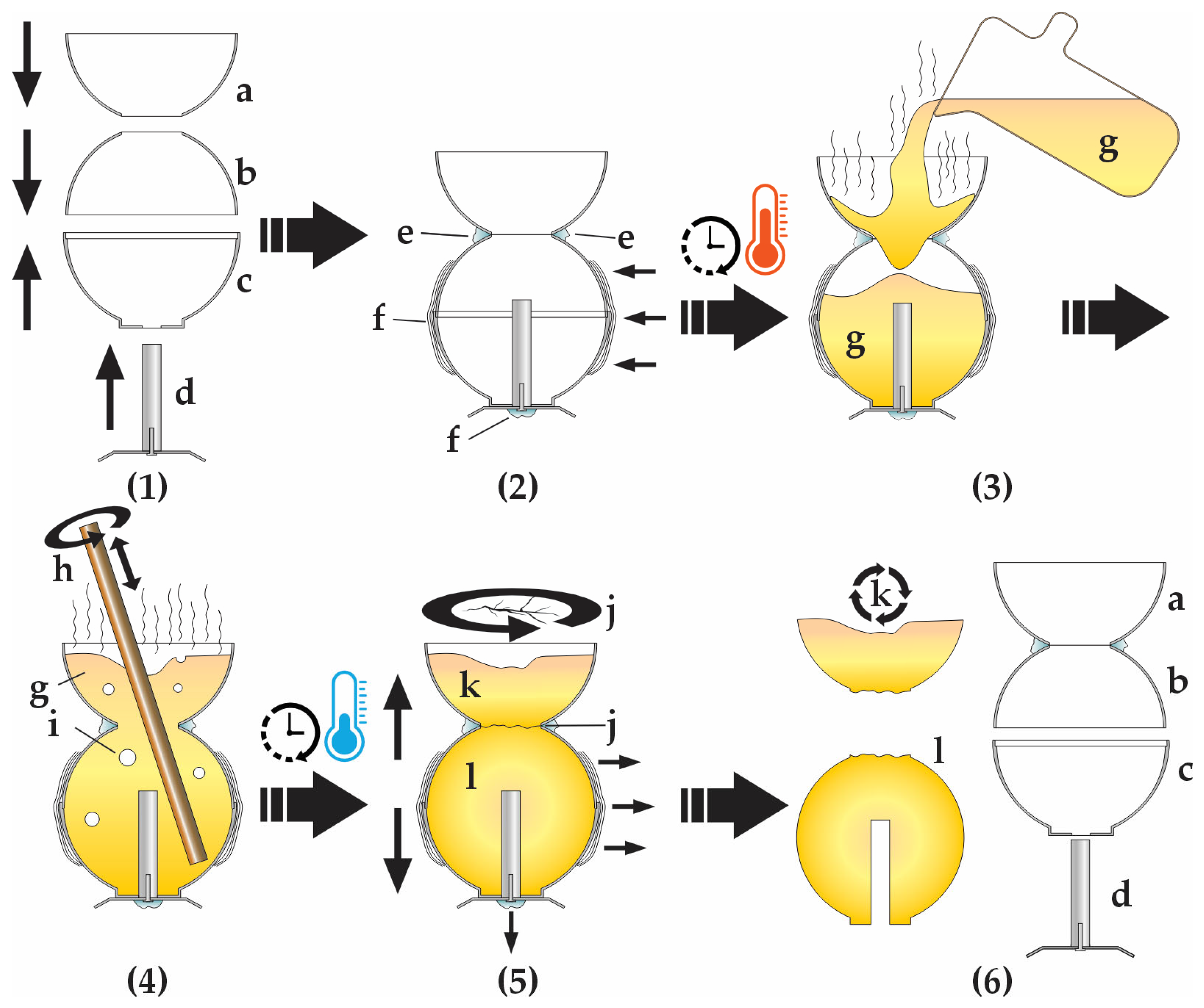
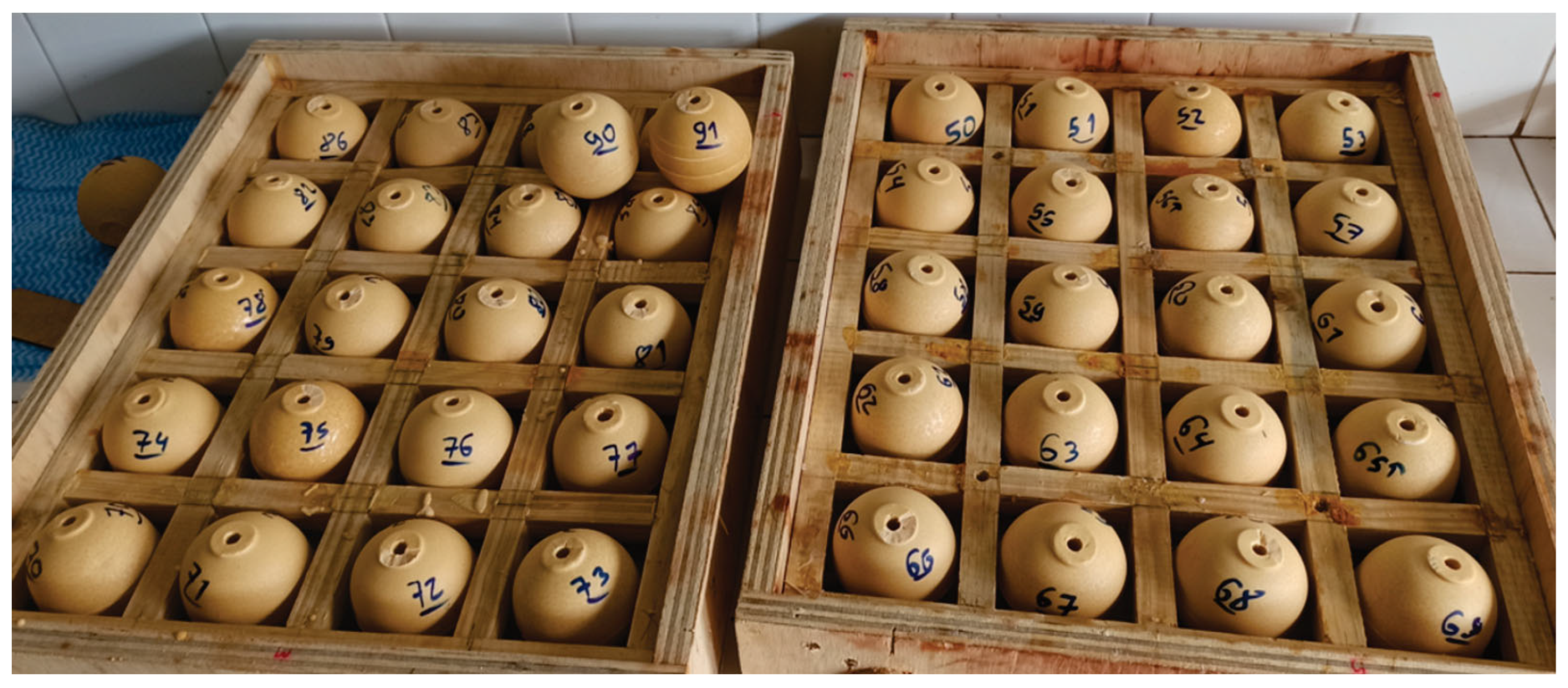
  • Reduced costs: The method should utilize cost-effective, accessible, and removable molds to load the charges, rather than expensive machined metal molds, given the complexity of the spherical shape. The selected material for the molds was 0.7 mm-thick 1050 aluminum, fabricated into bipartite spherical molds that are commercially available and commonly used in paraffin candle production. The molds used in this research had a diameter of approximately 72 mm and a unit cost of less than one dollar. Other diameters and similar models are also available in retail stores, as illustrated in [9] (the example is very similar but not identical to the material purchased in Brazilian markets).
  • Accessible Explosive: The selection of the explosive took into account several critical factors, including safety, cost, accessibility, power, castability, and the availability of well-established parameters. The explosives available to the research team that could meet these criteria included cast TNT, C4 (RDX + plasticizer), PBX (RDX or HMX + polymer), and cast Comp B (RDX + TNT + wax). C4 was deemed unsuitable due to its malleability, as it tends to lose its shape during testing. PBX was considered less ideal because it is more difficult to manufacture, more expensive, and available in a wide range of formulations. TNT and Comp B were ultimately determined to be the best options for this method due to their accessibility for defense research, ease of castability, well-established standards, safety profile, and good detonation power [10].

1.2. Experimental Tests and Analysis

A series of tests and analyses was conducted with the TNT and Comp B (comprising 60% RDX, 39% TNT, and 1% wax) charges, both validating the method of loading and providing the characterization:
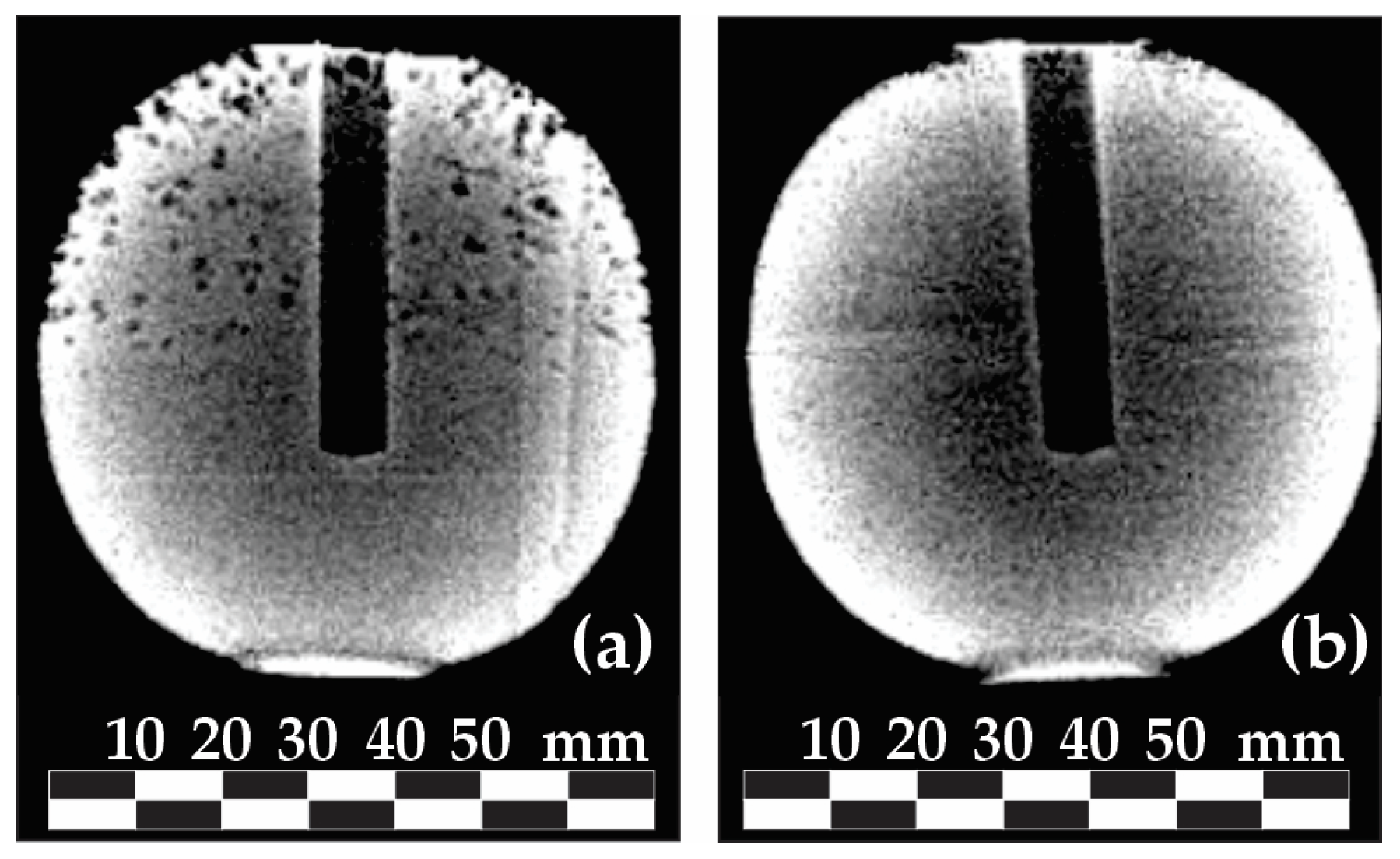
  • X-ray analysis of all charges was conducted to investigate voids, cracks, or other mechanical problems, as TNT-based cast explosives may encounter these issues during solidification and crystallization, which could interfere with explosive performance [10];
  • Measurement of the mass and density of the loaded explosive charges, demonstrating maintained load consistency with brief statistical analysis;
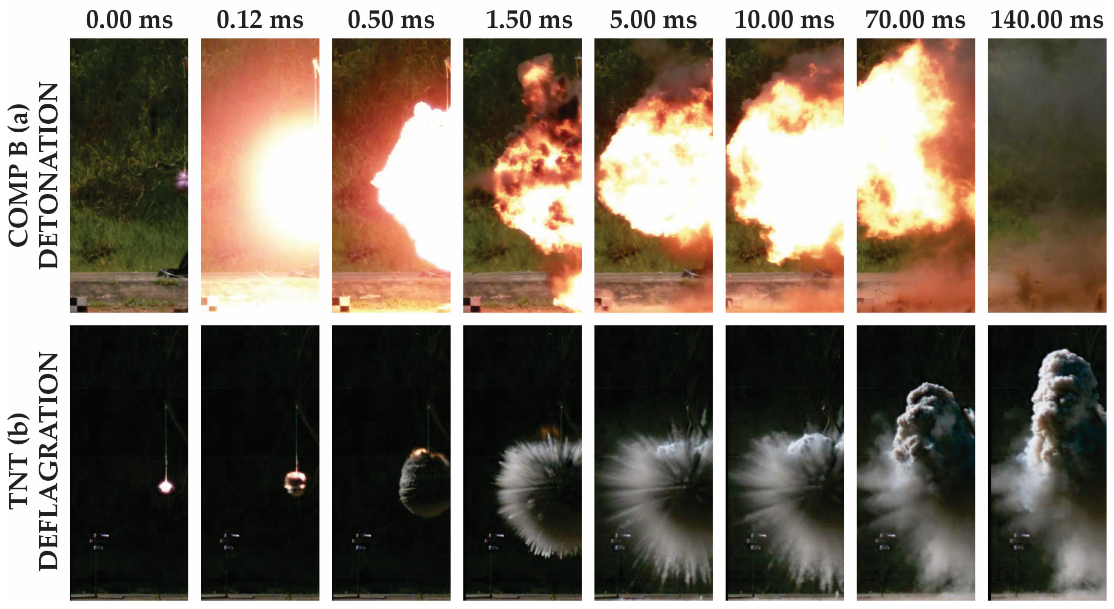
  • Five detonation field tests were conducted for each type of explosive. All five Composition B charges detonated without incidents, while the TNT charges deflagrated, indicating that TNT was not effective for this type of loading and dimensions. The TNT initiation problem can be explained by the high critical diameter necessary for this explosive when not confined [11,12,13];
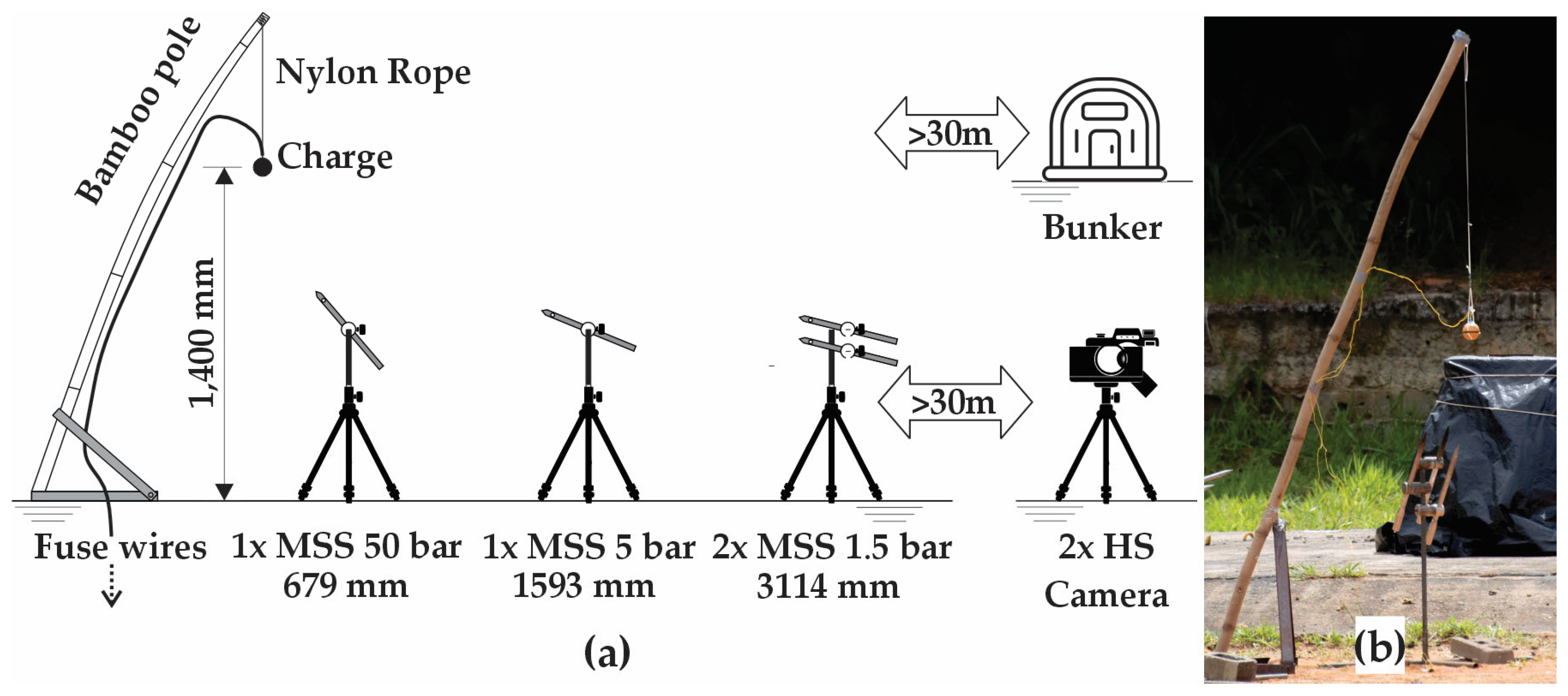
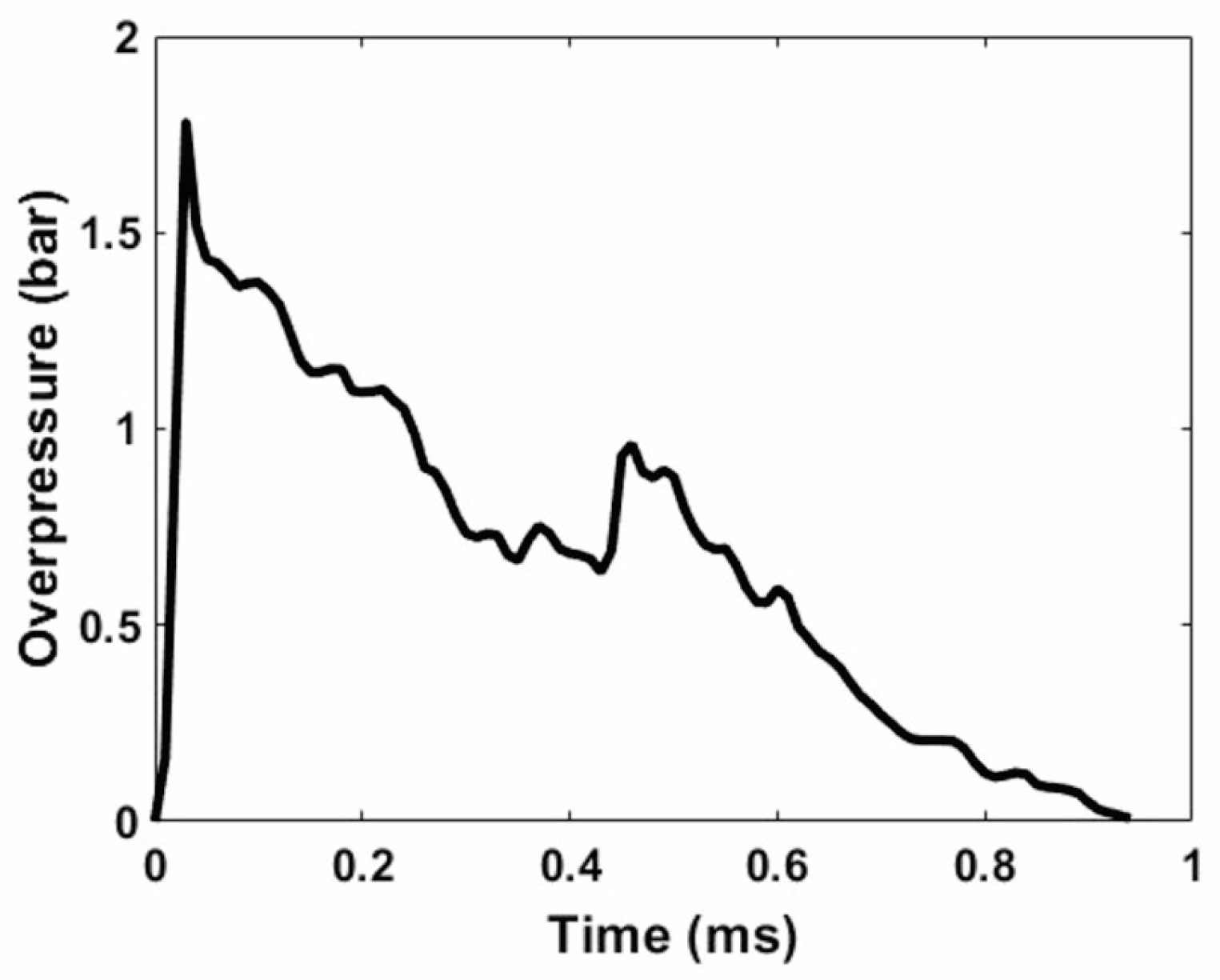
  • Measurement of the atmospheric overpressures generated by the charges’ detonation using memorizing shock wave measuring systems in three different distances for each detonation test;
  • TNT equivalence for pressure calculations of Composition B charges, compared with large-scale detonation events;
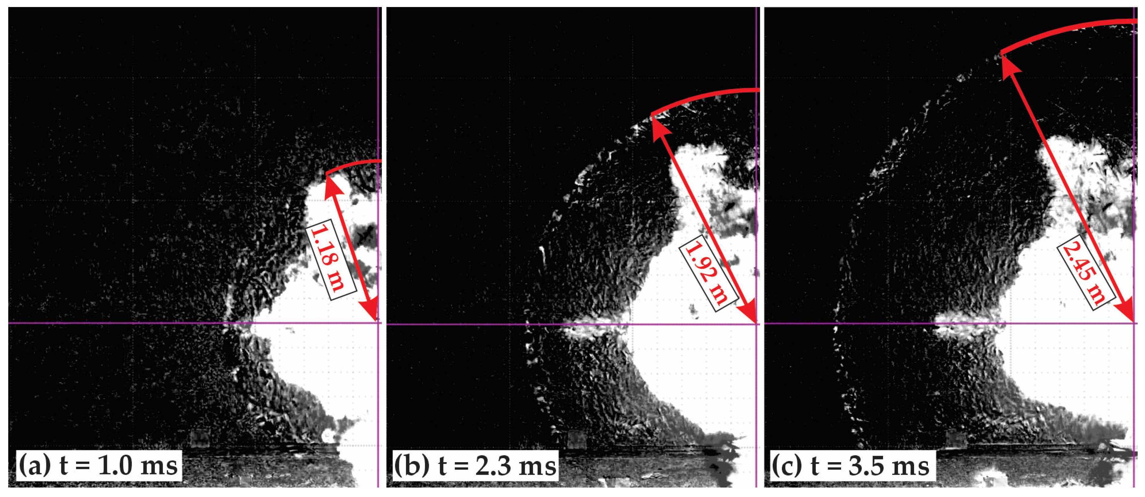
  • Visual analysis of high-speed camera footage, comparing the effects of detonation and deflagration processes and examining the shock wave pattern of the Composition B charges;
  • Other four specific detonation tests were conducted to characterize the detonation velocity of the charge;
  • Chemical stability testing of three Comp B explosive samples, verifying whether the loading method introduced any hazardous contamination;
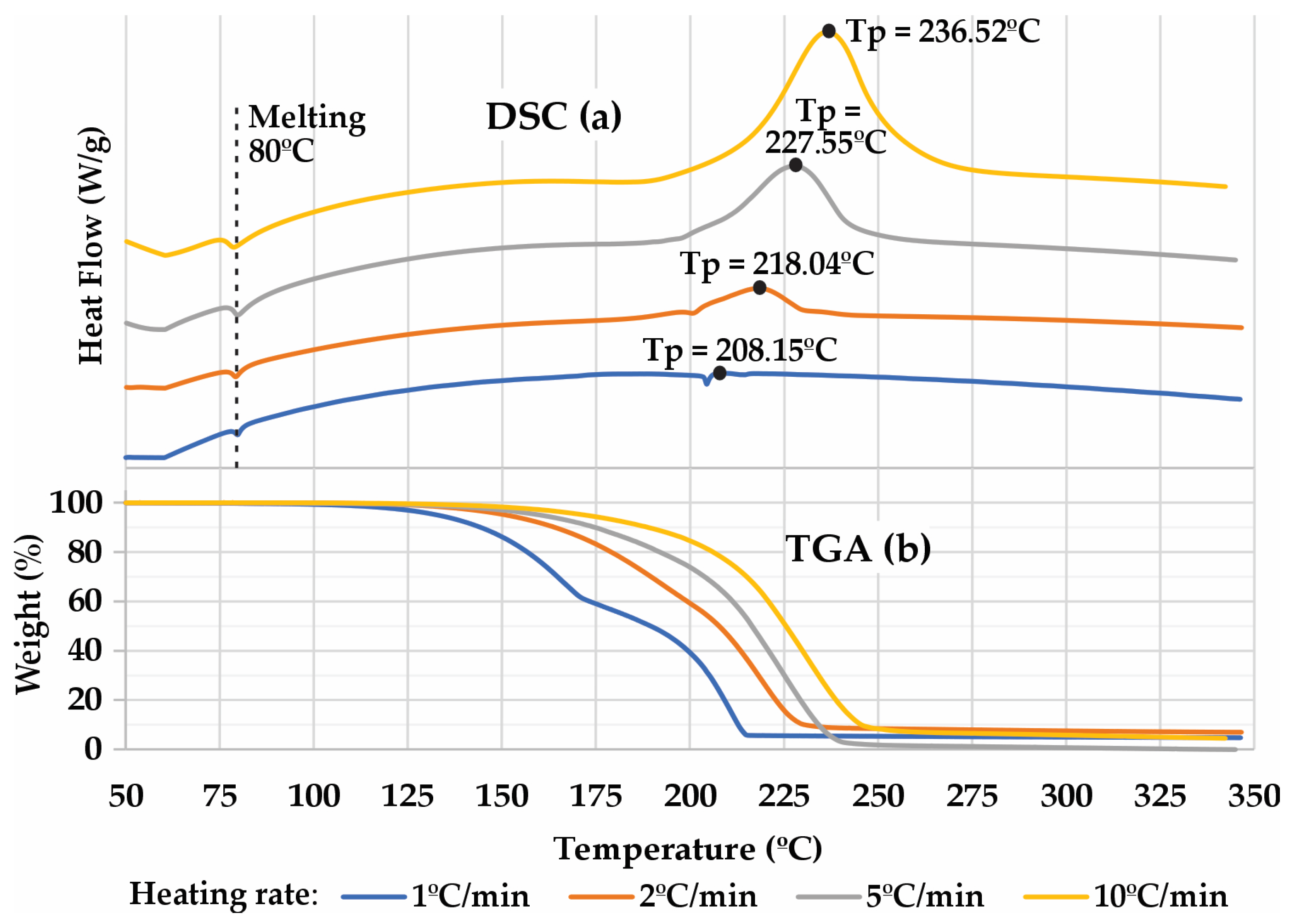
  • Thermal analysis using differential scanning calorimetry (DSC) and thermogravimetric analysis (TGA) was conducted on four Composition B samples at four different heating rates: 1, 2, 5, and 10 °C/min. The degradation temperatures of the charges and other important parameters are presented;
  • The activation energy of decomposition for the Composition B charges was calculated using two different methods and DSC results.

1.3. Positioning the Study in Modern Research

1.3.1. Blast Field Tests

The works of [14,15,16,17,18,19,20,21,22,23,24,25] are just a few examples of modern research utilizing high explosive detonations in open-field tests to study blast effects. Some studies focus on the damage to mechanical and civil structures, exploring methods to enhance resistance against explosions and comparing the results with computational models [14,15,16,17,18,20]. Others propose the application of polymer materials to concrete for improved detonation protection [22,23,25]. Additionally, some research examines the blast effect itself and its propagation, considering variations in parameters [19,21].
Inserted into the modern context of blast studies and their effects on structures, the presented method and comprehensive characterization offer a valuable tool for future research in the field, providing an affordable and tested approach for loading explosives. The small spherical Comp B charges yielded results closely resembling those observed in large-scale detonations, offering an opportunity for small-scale and safer detonation tests that simulate real events, such as terrorist attacks, bombardments, or accidents.

1.3.2. Explosive Thermal Analysis

Chemical thermal analysis, using methods such as differential scanning calorimetry (DSC), differential thermal analysis (DTA), and thermogravimetric analysis (TGA), can be used to identify or characterize explosives, as demonstrated by Nazarian and Presser [1,26,27]. These laboratory tests enable the calculation of key parameters, including the decomposition temperature and activation energy (Ea) of explosives [28]. These parameters are essential for establishing safety criteria and comparison.
A series of recent studies has analyzed the thermal characteristics of explosives and energetic materials, performing the described tests and calculations. Some of the materials studied using these techniques include propellant-polymers [29], CL-20-based polymer-bonded explosives [30], PETN, RDX, HNS, HMX [31], TNT, Amatol [32], explosives with ammonium perchlorate/ammonium nitrate and aluminum powder [33], energetic coordination compounds [34], NC/HTPB-based high-energy gun propellants [35], and TNT-based melt-cast explosives [36].
No studies were found in the open literature that investigated in depth the thermal characteristics of Comp B, including the formulation used in the present study, which comprises 60.0% RDX, 39.0% TNT, and 1.0% natural bee wax. Other sources refer to compositions with RDX/TNT/wax ratios of 63.0%/36.0%/1.0% [13], 60.0%/40.0%/0.0% [36], or 59.5%/39.5%/1.0% [37]. These are slight differences, and they will be used as references for comparing the Ea of the current composition. Other parameters, such as peak temperatures at different heating rates in DSC and TGA tests for Comp B, were not found in the literature. The Comp B formulation used is available in the Brazilian defense industry and is very similar to the American standard [37], with a difference of only 0.5% in the RDX content, resulting in no significant differences in performance or chemical properties. This is supported by the activation energy difference, which was approximately 2%.

1.4. Contribution to Structural Analysis Field

The current paper focuses on a blast load technique and the characterization of the method, validating it and providing crucial data. During testing, it is essential for any structural engineering or research endeavor to ensure that the load sources are reliable and accurately represent real-world conditions. Even if a team establishes an appropriate theory and testing layout, inaccurate load generation and imprecise data will lead to erroneous results. With this in mind, the following paragraphs will describe the main new contributions to structural analysis.
One of the challenges in academic structural testing is producing small and safe charges that can be detonated to reproduce spherical shock waves, even at close range. This is important because safer, smaller charges need to be placed closer to structural targets to replicate the same peak pressure. The most commonly used blast load theories by academic and engineering teams, such as those by Kinney and Graham [6] and Kingery and Bulmash [7], assume spherical shock waves, as real-world detonations exhibit this behavior. The current study addresses this issue by providing a replicable method for detonating small, bare, spherical charges initiated at the center. The results confirmed that the shock waves generated by the proposed method are indeed spherical at close range.
The TNT equivalence for pressure of the proposed charges is another important piece of data necessary for structural teams. This value defines the blast loads for different explosives and is used in most methods presented in academia, such as those by Kinney and Graham and Kingery and Bulmash. Even some programs and finite element methods (FEM) depend on the TNT equivalence value as a load input [3].
The explosive velocity of detonation provided is used in computational simulations, including Eulerian FEM, as it is the main parameter governing shock wave propagation. The Coupled Eulerian-Lagrangian (CEL) FEM combines Eulerian and Lagrangian algorithms to model the interaction between fluids and structures and is widely used by structural teams [3].
The chemical tests verify whether any contamination occurred using the proposed method and provide important safety data. Notably, no previous source has provided detailed TGA/DSC data at four different heating rates for Comp B. The decomposition temperatures and mass analysis during heating offer essential safety criteria for structural teams when loading and handling explosive charges. These results allow for determining the conditions under which the explosive begins to lose its properties or becomes hazardous under different heating scenarios. The activation energy analysis, compared with slightly different formulations, provides insights into how desensitizers and different explosives affect the stability of the explosive. Another important application of the resulting thermochemical data is its use in computational simulations that estimate the energy and volume of gases generated during detonation, which is valuable for certain structural analyses [12].
The high-speed camera footage and the comparison between detonation and deflagration processes, beyond demonstrating the spherical behavior of the shock wave, can assist structural test teams in identifying initiation issues. Initiating an explosive is not an easy task, especially on small scales, and determining whether the explosive properly detonated is crucial. An explosive that does not fully detonate can result in incorrect loads, leading to misinterpretation of results [12].
It is important to highlight that the proposed method can be adapted to meet different structural testing requirements without losing its low-cost advantage. As described, molds with various diameters are commercially available, allowing for different charge masses. By maintaining the scale and loading method, the results will remain consistent, as the provided data are scalable and independent of the load mass. Another advantage of the method is that, since the shock waves are spherical even at close range, it can be easily adapted to different stand-off distances and structure shapes. Therefore, any type of structural test can benefit from this method, including tests on concrete, steel, composites, wood, and other materials.
Although not the focus of the present paper, as the structural response analysis will be detailed in an upcoming article, a single test using a 2 mm thick A36 structural steel sheet will be presented to demonstrate the capability of the proposed method to generate damage to structures. The test method and additional details will be described in that future paper.

2. Materials and Methods

2.1. Explosive Loading Method

The TNT explosive was donated by IMBEL—Indústria de Material Bélico do Brasil and the Comp B by RJC Defesa Aeroespacial Ltda, both part of the Brazilian defense industry, which maintain not-for-profit partnerships with research institutes. IMBEL is located in Juiz de Fora, Minas Gerais, Brazil, while RJC is based in Lorena, São Paulo, Brazil. The molds used in this study were prepared by the academic team.
The aluminum molds, (a) and (c) in Figure 1, are divided into two halves that fit together to form the spherical shape. After the melted material cools and solidifies, both halves can be separated to access the cast. Some adaptations were made to the commercial mold to meet the demands of the explosive. A casting riser (a), made from one-half of the spherical aluminum mold, was adapted to the top of the mold to mitigate these problems. The other modification was the installation of a cylindrical aluminum bar (d) at the bottom of the mold. Once removed, this bar creates a central hole in the charge where the detonation fuse was installed.
Step 1 in Figure 1 shows the mold components. Each mold (b + c) had an equatorial interior diameter of 71.4 ± 0.1 mm and 72.8 ± 0.2 mm high, representing close to perfect spheres. The bars (d) had a diameter of 8.0 ± 0.1 mm and a length of 46.0 ± 0.1 mm. The mold’s interior volume, excluding the volume of the bar, was 205.4 ± 0.7 cm3.
Forty-three similar molds were assembled as shown in Step 2 of Figure 1. The adapted riser (a) was fixed and sealed to the top of the mold (b), having neutral-cure clear silicone sealant (e). The bar (d) was sealed with the same material (e). The mold halves (b and c) were sealed with duct tape (f), as it is easy to remove. No release agent was added to the interior of the molds, but the aluminum was cleaned and polished.
After the silicone had cured, the explosive was loaded, starting with Step 3 of Figure 1. A batch of each explosive was prepared and melted near the TNT melting temperature of approximately 80 °C [10]. Using small jugs, the liquid explosive (g) was poured into each mold. This process should be carried out carefully and slowly to avoid the formation of bubbles (i).
As observed in Step 4, the liquid explosive (g) was gently stirred with a bronze stick (h), another maneuver to remove air bubbles (i). Once all molds were charged and stirred, the process was halted for sufficient time to allow the explosive charges to reach room temperature naturally.
In Step 5, each solidified explosive charge (k + l) was removed from the molds. A gentle twist cracked (j) the explosive in the neck, which has a diameter of only 25.0 ± 0.1 mm. This crack separated the riser explosive (k) from the desired explosive load (l). The duct tape (f) was removed, as well as the aluminum bar (d).
All parts were separated (Step 6), and the riser explosive (k) was intended for reuse for recasting. The explosive charges (l) were inspected for any observable mechanical damage and stored for examination. The mold and its parts were cleaned and prepared for other necessary loads. Any charge lost due to mechanical damage during the demolding process was replaced with a new loading, and the explosive was reused.
Figure 2 illustrates the molds before (a) and after the loading process (b) for the Comp B explosive. The observable shrinkage in the figure demonstrates the importance of a riser volume to avoid problems with the explosive charge. Similar results were observed with TNT.

2.2. Initial Inspections and Analysis

During the demolding phase, each charge was inspected for visible mechanical problems, such as cracks or fractures, with any failures during the loading process being recorded. Defective charges were discarded and separated for reuse. After this process, all charges were X-rayed using a Poskom PXP-60HF (Goyang-si, Republic of Korea), regulated at 80 MHz.
The dimensions, masses, and bulk densities of the remaining charges were measured. A Torrey L-EQ 5 electronic scale (La Paz, Mexico), gauged the masses with a 5000 g maximum weight capacity and an accuracy of ±1 g. For dimensions, a Mitutoyo 500-196-30 (Kawasaki, Japan), Advanced Onsite Sensor Absolute Scale Digital Caliper with a maximum length of 150 mm and an accuracy of ±0.02 mm was used.
To appropriately calculate the apparent density of the charges, each finished mold was identified by numbers and had its internal volume pre-measured. Before measurement, the molds were filled with distilled water for half an hour to check for sealing, which is essential to ensure the safe loading of the explosive and accurate results. The internal volume of each mold was then measured three times using distilled water at a controlled temperature of 21 °C and a graduated cylinder with a maximum capacity of 500 cm3 and a precision of 1 cm3. Since the internal surface of the polished aluminum was hydrophobic, no water droplets were retained inside. This method ensured the correct volume determination, as it accounted for all irregularities and shapes of the explosive charge, including the initiator cavity.

2.3. Field Detonation Tests

2.3.1. Blast Testing

Five charges of TNT and five charges of Comp B were initiated to verify the success of their initiation, measure the blast overpressure at different distances, and record the shock wave pattern and speed using high-speed cameras (HSC). The tests were conducted at the detonation field of the Divisão de Sistemas de Defesa (Defense Systems Division—ASD). ASD is the defense division of the Instituto de Aeronáutica e Espaço (Institute of Aeronautics and Space—IAE), a research institute of the Força Aérea Brasileira (Brazilian Air Force—FAB).
During the field tests, a series of shock wave measuring systems (MSSs) was installed. This equipment measures atmospheric overpressure resulting from a detonation over time using high-sensitivity, high-load limit piezoelectric sensors. The system used was the B261 MSS from High Pressure Instrument Company, featuring a sensor linearity of 2% of the full scale. One MSS with a maximum pressure of 50.0 bar was installed at 679 ± 1 mm from the detonation center, another with a maximum pressure of 5.0 bar at 1593 ± 1 mm, and two sensors with a maximum pressure of 1.5 bar were installed at 3114 ± 1 mm, as shown in Figure 3.
All positions at the test site were ensured using prefabricated hard bars with the required measurements. Each bar length was measured using a calibrated meter with a precision of ±1 mm. Some distances at the test site, such as the positions of the pressure sensors, were determined using two bars—one to measure the height and another to measure the horizontal distance—while the actual straight distance was calculated using geometric relations. To ensure accurate positioning, a plumb line was used, and the test was conducted under no-wind conditions, which was easily achieved as the test arena was enclosed on all sides by blast protection embankments.
The environmental atmospheric factors, such as pressure variations, were considered during the TNT equivalence calculation through the pressure correction factor (Sp) and distance correction factor (Sd), which are detailed in Section 2.3.3.
The detonation events were recorded by two high-speed cameras installed more than 30 m away from the explosive, a distance sufficient to ensure no damage to the equipment. The cameras used were Phantom VEO 640 models, with specifications detailed in the manufacturer’s datasheet [38]. The lenses mounted on the cameras were Nikkor 50 mm f/1.2. One of the cameras recorded the footage at 10,000 fps with a resolution of 1152 × 320 pixels. The other was recorded at 8000 fps with a resolution of 768 × 720 pixels. Both recorded no more than 140 ms of the event.
As illustrated in Figure 3, the explosives were detonated 1400 mm above the ground, tied to a nylon rope that was then attached to a bamboo pole. These materials do not release debris that could be dangerous. To initiate the explosive, an electric blasting cap No. 8 was used as the fuse, and a cylindrical pellet of bare compressed RDX weighing 1.4 g was used as the booster. The booster was inserted into the charge’s cavity in such a way that its center of mass coincided with the center of mass of the explosive sphere. A pair of fuse wires connected the electric blasting cap to the test management bunker, where the technical team was sheltered, more than 30 m away from the detonation.

2.3.2. Detonation Velocity Testing

Four additional charges were detonated specifically to measure the detonation velocity (DV) of the explosive, using the same layout as shown in Figure 3, but with modifications to the sensor setup. The DV represents the speed at which the explosive chemical reaction propagates through the material, making it a critical parameter for assessing explosive performance. The measurement system included a set of 0.7 mm needles inserted into the explosive charge. These needles were connected by long cables to an instrumentation system. Upon being struck by the detonation, the needles underwent an ionization process that disrupted electrical continuity. The instrumentation system detected this disruption and recorded the time at which the detonation wave reached each needle. That is a common method of measuring DV [13].
The first explosive charge of each explosive was equipped with needles connected to an oscilloscope and other needles connected to a precision timer. The other three charges were prepared with only the needles connected to the timer. Each set of needles operated independently, with no interference between them due to the detonation process. The oscilloscope used was an MSO6014A Agilent Mixed Signal with a 100 MHz frequency and a sensitivity of ±0.01 µs. The timer was a Solution Crono24 configured with a 10 MHz frequency and a sensitivity of ±0.1 µs.

2.3.3. TNT Equivalence

The TNT equivalence represents the power of an explosive relative to TNT, based on the mass ratio for a specific parameter. It serves as a measure to evaluate the overall performance of an explosive charge. This value can be determined for various parameters, such as atmospheric peak overpressure, generated impulse, heat of detonation, and others [39].
This present research utilized the peak overpressure to calculate the TNT equivalence of the charges under study. The reference peak overpressure was determined using the established Kingery and Bulmash (K&B) equations [7], which are commonly applied to calculate large-scale explosion events.
Using the measured peak overpressure obtained during the tests (Pso), the K&B equations, and considering a pressure correction factor (Sp), it is possible to calculate the reference scaled distance (Z0). Z is an important parameter in explosive engineering [39], representing a parameterized distance as a function of the stand-off distance (R), the mass of the explosive (W), and a distance correction factor (Sd), calculated according to Equation (1) [7]. Equations (2) and (3) present the Sp and Sd formulas, respectively. These factors account for atmospheric variations based on the sea level reference pressure (P0) and local test atmospheric pressure (Pa) [7].
Z = R / S d W 3
S p = P a / P 0
S d = P 0 / P a 3
The scaled distance for the tested charge (ZC) was calculated using Equations (1) to (3), as R, W, and Pa were measured in the tests. Knowing the reference (Z0) and the charge (Zc) scaled distances, it is possible to calculate the TNT equivalence for the charges using Equation (4) [40].
T N T e q = Z C / Z 0 3

2.4. Laboratory Tests

During the field detonation tests, the TNT charges proved to be unviable for use with the method presented in the current paper. However, the Comp B formulation demonstrated good results. For this reason, further laboratory tests were conducted on this composition to determine if any possible contamination had affected the stability and safety of the explosive and to provide additional novel information about the explosive used in the present study.
Samples from Comp B charges were collected to perform chemical stability tests and DSC/TGA thermal analysis.

2.4.1. Chemical Stability Test

The objective of the test is to evaluate the chemical stability of explosives and pyrotechnics by heating the material and measuring gas evolution. The apparatus measures the volume of gas released by heating samples in test tubes under vacuum in a heating block maintained at a constant temperature (30–160 °C) for a specified period to determine whether the thermal stability condition of the energetic material is satisfactory. The release of gas up to a certain volume indicates that the explosive is chemically stable and that there were no problems during fabrication, transportation, and storage. The test follows STANAG 4556: Explosives, Vacuum Stability Test, published by NATO [41].
Three samples of 5.0 g were collected from the charges. They were weighed using a Mettler AE160 Digital Analytical Balance with a 160 g maximum weight capacity and an accuracy of ±0.001 g. The samples were heated for 40 h at a constant temperature of 100 °C, using an OZM Research Vacuum Stability Tester STABIL VI®. The vacuum was equal to or less than 1% of the atmospheric pressure. The equipment measured the volume of gas released per mass of the sample, with an accuracy of ±0.001 cm3/g. If the gas volume is lower than 2.000 cm3/g, the explosive is considered stable [41].

2.4.2. DSC and TGA

The DSC and TGA tests made with Comp B samples were performed by IAE. Four heating rates were adopted with sample masses of 0.0025480 g, 0.0036150 g, 0.0026380 g, and 0.0025570 g at the rates of 1, 2, 5, and 10 °C/min, respectively. This allows for a thermokinetic analysis, leading to the calculation of Ea, as will be described later. The samples were heated from 50 °C to 350 °C, covering all significant thermal events in the Comp B explosive.
The TA Instruments SDT Q600 V8.3 Build 101 enables simultaneous measurement of weight changes (TGA) and precise differential heat flow (DSC) in a single sample, from ambient temperatures up to 1500 °C. The balance sensitivity is 10−7 g, the thermometer precision is 0.001 °C, and the calorimetric accuracy is ± 2 %. Further details can be found in the equipment’s technical sheet [42].
The tests were conducted in a 99.99999 % purity nitrogen environment with a constant flow of 100 cm3/min of this inert gas. Consequently, the tests occurred under controlled conditions with no oxidation process. Under these conditions, it is possible to observe the decomposition of the explosive without any combustion reactions.

2.4.3. Activation Energy Calculation

The activation energy of the explosive was calculated using the Kissinger [43,44] and Ozawa [44,45] methods, based on results obtained from DSC analyses. Both methods are derived from traditional chemical kinetics equations, such as the reaction rate equation and the Arrhenius equation, incorporating some simplification assumptions. From these equations, it is possible to derive the fraction of chemical decomposition (α) over time (t) as a function of the Arrhenius pre-exponential factor (A), activation energy (Ea), universal gas constant (R), temperature (T), and reaction order (n), as shown in Equation (5).
d α / d t = A   e x p ( E a   /   R T )   ( 1 α ) n
The maximum reaction rate is reached when d2α/dt2 = 0. By differentiating Equation (5), Equation (6) is obtained.
( E a     β ) ( R   T p 2 )   = A   n   e x p E a R   T p   ( 1 α ) n 1
where Tp is the peak temperature observed on the DSC curve at a linear heating rate equal to β = dT/dt. The Kissinger method [43,44] assumes that the term A n (1α) n−1 does not depend on β. This leads to Equation (7).
d l n ( β   /   T p 2 ) d ( 1   /   T p )   = E a   R
In the Kissinger method, the activation energy Ea can then be calculated from the slope (−Ea/R) of the linear plot of ln (β/Tp2) versus 1/Tp.
For a constant linear heating rate, given by β = dT/dt, Equation (5) can be converted into Equation (8):
0 a d α f ( α ) = A   β     T 0 T exp E a R T   d T  
In the Ozawa method [44,45], A, f(α), and Ea are considered to remain unaffected by T, while A and Ea are also regarded as independent of the conversion rate α. By separating terms and integrating Equation (8), the Ozawa equation is derived as Equation (9).
l o g   f α = l o g   A     E a R l o g   β 2.315 0.4567     E a R   T p    
A linear plot is produced by graphing log β against 1/Tp. From this plot, the activation energy Ea can be calculated from the slope as described by Ozawa, which is defined by −0.4567 Ea/R.

3. Results and Discussion

The measurement uncertainties were considered during the analysis of the results. Type A uncertainty, derived from statistical analysis of repeated measurements, was calculated using the standard deviation, mean, number of measurements, and Student’s t-distribution with a 95% confidence interval. Type B uncertainty, related to equipment imprecision, was obtained from the calibration certificates of the equipment. All equipment was calibrated up to date, and the precision values were presented in Section 2. Uncertainty propagation during operations, such as average calculations, was considered and properly calculated following well-known international standards.
Other types of errors and discrepancies will be discussed immediately after the presentation of the results, aiding in the comprehension and cohesion of the article.

3.1. Initial Inspections and Analysis Results

The loading process for both explosives was successful, with minor losses of around 10% due to demolding issues or mechanical failures. The absence of a demolding agent proved unproblematic, as the explosive did not stick to the aluminum. Table 1 summarizes the results of the loading process.
The charges exhibited good consistency, with a relative mass variation of ±4.60% for TNT and ±1.95% for Comp B. The larger mass variation for TNT can be attributed to the presence of bubbles observed in the X-ray analysis, an issue not present in the Comp B charges. The measured density was 1.60 ± 0.01 g/cm3 for TNT and 1.63 ± 0.01 g/cm3 for Comp B. The reported density ranges are 1.50 to 1.60 g/cm3 for TNT and 1.61 to 1.72 g/cm3 for Comp B [13], indicating that both materials were within the expected values when using other methods.
Externally, the charges exhibited a well-formed surface, devoid of irregularities, deformations, or defects, as illustrated in Figure 4 and Figure 5. Figure 4c displays a split charge of Comp B that was discarded, revealing the interior of the explosive and the central cavity for initiation. No interior visible defects were observed.
During the X-ray analysis, the TNT charges exhibited pronounced bubble and void formation issues, as shown in Figure 6a. Despite implementing a series of loading measures to mitigate this defect, the thin mold and spherical shape did not allow the TNT to release the voids formed during crystallization. On the other hand, Comp B, due to the presence of RDX crystals, presented a clear X-ray image, as illustrated in Figure 6b.

3.2. Field Detonation Tests Results

All detonation tests occurred without incidents. However, none of the TNT charges were able to achieve detonation, instead exhibiting a deflagration reaction. Comp B charges detonated within the expected parameters, as will be detailed in the next sections. The first noticeable difference between the two reactions was observed by the field test team. The TNT tests produced a much quieter shock sound, a higher-than-expected presence of smoke, and a strong smell of gunpowder compared to the successful detonations of the Comp B charges.
The high-speed cameras captured the differences as well, as shown in Figure 7. The entire chemical reaction of Comp B (a) was completed within the first 0.12 ms, evidenced by the intense light released. No residual material was observed at 140 ms, and no explosive material was dispersed into the atmosphere. In contrast, the TNT deflagration process was still ongoing at 140 ms, with significant fume generation and explosive material dispersal. This footage highlights the differences between a detonation and a deflagration, particularly in terms of reaction velocity and the level of power released.
Some explanations can be provided for the inefficiency of TNT. The most accepted by the academic team is that the initiation system, limited by the small size of the method, lacked the critical diameter required to initiate TNT. This is because cast, unconfined TNT has a high critical diameter [12]. Increasing the booster size is not considered viable, as Comp B charges yielded good results, and a larger central hole would significantly distort the spherical shape.

3.2.1. Overpressure Measurements

In all TNT tests, the pressure remained below 0.05 bar, the minimum readable value of the MSS, resulting in no recorded data. This is further evidence that TNT charges did not detonate, as the expected value for detonation at 3114 mm was 0.37 bar [7].
The successful Comp B detonation tests were identified as T1 to T5. MSS reading failures occurred in one sensor during tests T2 and T5. The pressure versus time curve acquired by the 5 bar MSS in test T3 is plotted in Figure 8. All peak overpressure values and their averages for each distance, along with the associated uncertainty, are listed in Table 2. This table also presents theoretical values expected based on the TNT equivalence from various sources [39,40,46] and calculated by the K&B equations [7].
The measured overpressures were within the expected theoretical values when compared with three different sources. This demonstrates that the loading method was successful in terms of explosive performance, even at close ranges such as 0.68 m.
The overpressure versus time curve acquired showed a sudden rise in atmospheric pressure followed by a decrease, which is expected for a detonation shock wave. A second, smaller pressure peak was measured, caused by the reflection of the shock wave on the ground, as the explosive was positioned 1400 mm high and the 5 bar sensor was 1590 mm away. However, this reflection measurement did not affect the overall results.

3.2.2. TNT Equivalence Results

All peak overpressure measurements obtained from the pressure gauges during Comp B tests were processed using the method described in the previous section to calculate their corresponding TNT equivalents. The data were then averaged, its uncertainty quantified, and the results were compiled in Table 3 for comparison with reference values [39,40,46]. The TNT equivalences were calculated by distance and global average.
The experimental results presented align with the references [39,40,46], particularly those derived from peak overpressure tests [39,40]. Table 3 shows a trend of increasing TNT equivalence at greater distances; however, this may be attributed to experimental and KB curve uncertainties, as there is overlap among the ranges. The mean TNT equivalence value for each measurement distance deviates by less than 6% from the global average, which is consistent with other studies that report minimal variations in this factor over different distances [47,48].

3.2.3. Detonation Shock Wave

The atmospheric shock wave produced by the Comp B charges was captured by the high-speed cameras. No shock wave was observed during TNT detonation tests. All tests presented similar results on both cameras, and three frames from the footage of Test T2 are shown in Figure 9. Filters were applied to enhance the images by removing the background, adjusting the brightness, and desaturating the colors, making it possible to observe the spherical shock wave propagation and its radius.
In all tests with Comp B, the detonation shock wave maintained a perfectly spherical shape, even at close range, providing important evidence that the chosen charge shape produced a blast with characteristics similar to large-scale events. The high-speed footage was also used to measure the average shock wave propagation velocity. Based on Figure 9, the average velocity was approximately 569 m/s from 1.0 to 2.3 ms and 441 m/s from 2.3 to 3.5 ms. The approximate theoretical averages are 580 m/s and 458 m/s, respectively, with experimental differences of less than 4% [7].

3.2.4. Explosive Detonation Velocity Results

The detonation velocity tests were designated as V1 to V4. The average detonation velocity was determined by calculating the ratio of the distance between the needle sensors (∆d) to the difference in their measured times (∆t). No results were obtained during the TNT tests, as the deflagration process was unable to trigger the system. Table 4 summarizes the values obtained.
The results were consistent across the various charges and equipment, exhibiting an average velocity of 7.5 ± 0.1 mm/μs. This value is approximately 2% lower than the reference value for Composition B with a similar density [13], further demonstrating that the performance parameters are close to the expected values.

3.3. Laboratory Tests Results

As described, further laboratory tests were conducted on samples collected from the Comp B charge. No tests were performed on TNT, as this explosive was deemed unsuitable for the proposed method.

3.3.1. Chemical Stability Test Results

The equipment measured the volume of gas released from the explosive samples heated for 40 h at a constant temperature of 100 °C under vacuum conditions to assess chemical stability. The results of the test are presented in Table 5, demonstrating that the explosive is stable according to [41]. This confirms that the aluminum mold did not affect the chemical stability of the explosive.
The maximum difference in the volume of gas between the samples was approximately 5% of the average value. Although the samples were from the same batch of Comp B, they were not collected from the same explosive charge or at the exact same moment to ensure maximum coverage of the batch loading. Noting that 47 charges were loaded, such small differences between the samples are expected. It is important to note that the maximum volume of gas observed represented around 16% of the stability threshold, and the difference between the samples was only 0.8% of this limit. Thus, these differences were insignificant in terms of representing a stability problem.

3.3.2. DSC and TGA Results

The results of the DSC and TGA tests are shown in Figure 10. The temperature of the sample is represented on the x-axis, common to both results. The heat flows during the DSC test (a) for the different heating rates are presented in the same graph, shifted for optimal visualization. The most important temperatures are highlighted: the peak temperatures observed (Tp) and the melting temperature of the explosive. The weight percentage relative to the initial sample mass in the TGA tests (b) is also presented for different heating rates.
Analyzing the DSC/TGA graph, the first observed parameter is the thermal degradation temperature of the material. This temperature increases with higher heating rates [10]. The heat flow peaks occurred at temperatures of 208.15 °C, 218.04 °C, 227.55 °C, and 236.52 °C for heating rates of 1 °C/min, 2 °C/min, 5 °C/min, and 10 °C/min, respectively. The only available reference indicates a peak of 244 °C for a heating rate of 10 °C/min in a slightly different formulation [36]. An endothermic region can be observed at 80 °C in all tests, representing the melting of the Comp B mixture.
The autoignition or thermal degradation temperature for Comp B is reported in various sources to range from 174 °C to 224 °C [12,37,49], which is comparable to the results observed in the DSC tests. However, in the TGA tests, slight initial degradation was observed at a heating rate of 1 °C/min between temperatures of 100 °C and 125 °C. This information is significant, particularly during the manufacturing process, when the explosive is heated to melt. Although the explosive does not ignite at these temperatures, it will begin to degrade and lose its properties.
During TGA tests, the complete degradation of the used Comp B occurred between 200 °C and 250 °C, leaving around 5% to 10% residual material. The same test in classical literature [10,13], only conducted at a heating rate of 10 °C/min, shows degradation beginning at approximately 170 °C and completing at 220 °C. While not identical, these results are similar to those of the current explosive. The primary difference lies in the percentage of residual material; literature sources [10,13] report around 20% residual material, higher than the observation in Figure 10. This discrepancy can be attributed to two factors: the Comp B used exhibits higher purity, and the TGA tests in this study were conducted under a renewed neutral atmosphere, which aids in eliminating product gases and allows more reagents to decompose.

3.3.3. Activation Energy

The activation energy (Ea) of Comp B explosive was calculated using the DSC test results and the Kissinger [43] and Ozawa [45] methods. The results are presented in Table 6, alongside three reference values for comparison.
The analysis of the activation energy (Ea), using the Kissinger and Ozawa methods, yielded values of 160.22 KJ/mol and 160.18 KJ/mol, respectively. The difference between the methods was less than 0.03%, indicating high accuracy in the tests and analyses. The Ea found was approximately 7% higher than that of an RDX and TNT mixture without wax [36], suggesting that this desensitizing material enhances the stability of the mixture. Compared with an American military standard [37], the difference was about 2%. In contrast, compared with another formulation richer in RDX [13], the Ea of proposed Comp B was about 11% lower. This indicates that RDX contributes to increasing the Ea of the mixture, as also found in [36].

3.4. Illustrative Example of the Use of Charges in a Structural Test

Although not the focus of this paper, an example of the use of the proposed explosive charge will be presented. The method, layout details, results, and additional information will be described in an upcoming paper. The example involves the detonation of a 334 g Comp B charge at a stand-off distance of 300 mm from a 2 mm thick A36 structural steel sheet. The sheet was fixed along opposite edges in a robust steel support, with a span of 431 mm and a width of 400 mm.
Figure 11a shows the test layout just before detonation, while Figure 11b displays the resulting deformed steel sheet, demonstrating the excellent capability of the proposed method to generate loads on structures. As described, the stand-off distance and charge mass can be easily adjusted, as the method uses commercial molds and explosives, allowing each research team to adapt the charge to different structural materials and shapes.

4. Conclusions

The paper presented a method for loading cast explosives using off-the-shelf, low-cost, and removable aluminum molds. The explosives tested were TNT and Comp B, resulting in spherical bare charges with a mass of approximately 330 g. These charges have sufficient power for use in field tests, while their controlled mass and the absence of fragments proved safe within a radius greater than 30 m.
The cast TNT charges formed voids during loading and were unable to detonate at the small size of the charge and without confinement, proving unsuitable for the method presented. However, Comp B achieved good results. The loading process of more than forty charges yielded a success rate of over 90%. It is important to note that all discarded Comp B charges can be remelted and reused. No voids or defects were found during X-ray analysis, and the mass variation remained below 2% of the average.
During the field detonation tests, the five Comp B charges tested demonstrated performance similar to that expected in large-scale events. The blast shock wave generated had a perfect spherical shape and an appropriate propagation velocity, even at close range. The measured peak overpressures were consistent with those observed in large detonations, with an average TNT equivalence, based on this parameter, of 1.38.
The detonation velocity of the material, determined in four additional detonation tests, resulted in an average value of 7.5 mm/μs.
Samples of the used Comp B charges were collected to check their explosive stability and perform thermal DSC/TGA tests. The tests revealed no stability or thermal issues. The Activation Energy (Ea) of decomposition, calculated using two different methods, was within the range of the academia for similar methods of loading. It is worth noting that the formulation of Comp B can slightly vary depending on the source, with small differences in the ratios of RDX and WAX mixed into the TNT base.
Additionally, the current DSC/TGA tests provided novel information not found in other sources about the Comp B explosive. The analyses were performed at four different heating rates, with the complete data set including peak decomposition temperatures, detailed results, and the methods used.
For a future publication, the research team utilized the remaining Composition B charges to study the blast effects on structural steel sheets, as the method demonstrated both reliability and safety for structural research purposes. An illustrative example of these tests is presented in Section 3.4.

Author Contributions

Conceptualization, A.S.A., G.U., C.B.A., R.E.L.J., F.B.M., J.A.F.F.R. and K.I.; methodology, A.S.A., G.U., F.B.M. and J.A.F.F.R.; validation, A.S.A., C.B.A. and G.U., formal analysis, A.S.A. and C.B.A.; investigation, A.S.A. and C.B.A.; resources, A.S.A., R.E.L.J. and G.U.; data curation, A.S.A., C.B.A. and G.U.; writing—original draft preparation, A.S.A. and C.B.A. writing—review and editing, G.U., F.B.M., J.A.F.F.R. and K.I.; visualization, A.S.A., G.U., C.B.A., R.E.L.J., F.B.M., J.A.F.F.R. and K.I.; supervision, K.I.; project administration, A.S.A. and G.U. All authors have read and agreed to the published version of the manuscript.

Funding

This research received no external funding.

Data Availability Statement

The original contributions presented in the study are included in the paper and further inquiries can be directed to the corresponding author.

Acknowledgments

We sincerely thank RJC Defesa Aeroespacial Ltda for supplying the Comp B explosive and initiators, and IMBEL—Indústria de Material Bélico do Brasil for providing the TNT explosive. Our gratitude also extends to the Instituto de Aeronáutica e Espaço (IAE) for granting access to their detonation test field and providing their exceptional expert team, as well as for conducting the DSC and TGA tests.

Conflicts of Interest

The authors declare no conflicts of interest.

References

  1. Nazarian, A.; Presser, C. Forensic analysis methodology for thermal and chemical characterization of homemade explosives. Thermochim. Acta 2014, 576, 60–70. [Google Scholar] [CrossRef]
  2. United Nations. International Ammunition Technical Guidelines—IATG 01.08, 3rd ed.; United Nations: New York, NY, USA, 2021; Available online: https://unsaferguard.org/un-saferguard/guide-lines (accessed on 3 April 2025).
  3. USDOD. Structures to Resist the Effects of Accidental Explosions—UFC 3-340-02; United States Department of Defense (USDOD): Washington, DC, USA, 2008; p. 1943.
  4. Mendonça, F.B.; Urgessa, G.S.; Almeida, L.E.N.; Rocco, J.A.F.F. Damage diagram of blast test results for determining reinforced concrete slab response for varying scaled distance, concrete strength and reinforcement ratio. An. Acad. Bras. Ciênc. 2021, 93, e20200511. [Google Scholar] [CrossRef] [PubMed]
  5. Esparza, E.D. Spherical equivalency of cylindrical charges in free-air. In Proceedings of the 25th Department of Defense Explosives Safety Seminar, Anaheim, CA, USA, 18–20 August 1992; pp. 404–428. Available online: https://www.researchgate.net/publication/235193804_Spherical_Equivalency_of_Cylindrical_Charges_in_Free-Air (accessed on 3 April 2025).
  6. Kinney, G.F.; Graham, K.J. Explosive Shocks in Air, 2nd ed.; Springer Science+Business Media, LLC: New York, NY, USA, 1985; p. 269. Available online: https://link.springer.com/book/10.1007/978-3-642-86682-1 (accessed on 3 April 2025).
  7. Kingery, C.N.; Bulmash, G. Technical Report ARBRL TR-02555—Airblast Parameters from TNT Spherical Air Burst and Hemispherical Surface Burst; Aberdeen Proving Ground, Army Armament and Development Center, Ballistic Research Laboratory: Aberdeen, MD, USA, 1984. [Google Scholar]
  8. Mendonça, F.B.; Urgessa, G.S.; Domingues, M.G.; Iha, K.; Rocco, J.A.F.F. Efeitos do EPS na leitura de pico de pressão refletida em ensaio de campo com explosivo militar. Spectrum 2023, 24, 49–53. [Google Scholar] [CrossRef]
  9. Amazon Company. 12Pcs Semicircular Bath Molds Aluminum Alloy Half Ball Molds for Crafting Soaps Candles and Cakes for DIY Projects and Baking Supplies. Available online: https://www.amazon.com/IWOWHERO-Hemisphere-Steamer-Aluminum-Semicircle/dp/B0CN5T7RDG/ref=asc_df_B0CN5T7RDG?mcid=2b07c447b12c353989725ffce5404df0&hvocijid=10343000496065635276-B0CN5T7RDG-&hvexpln=73&tag=hyprod-20&linkCode=df0&hvadid=721245378154&hvpos=&hvn (accessed on 9 January 2025).
  10. USDOD. TM 9-1300-214—Military Explosives; United States Department of Defense (USDOD): Washington, DC, USA, 1984.
  11. Department of the Army. Explosive Trains; Department of the Army: Alexandria, VA, USA, 1974. [Google Scholar]
  12. Cooper, P.W. Explosives Engineering; Wiley-VCH: New York, NY, USA, 1997. [Google Scholar]
  13. Dobratz, B.M.; Crawford, P.C. LLNL Explosives Handbook: Properties of Chemical Explosives and Explosive Simulants; Lawrence Livermore National Laboratory—University of California: Livermore, CA, USA, 1985; p. 526. [Google Scholar]
  14. Zhang, P.; Cheng, Y.; Liu, Y.J.; Zhang, C.; Hou, H.; Wang, C. Experimental study on the dynamic response of foam-filled corrugated core sandwich panels subjected to air blast loading. Compos. Part B Eng. 2016, 106, 67–81. [Google Scholar] [CrossRef]
  15. Syed, Z.I.; Raman, S.N.; Ngo, T.; Pham, T. The failure behavior of reinforced concrete panels under far-field and near-field blast effects. Structures 2018, 14, 220–229. [Google Scholar] [CrossRef]
  16. Khan, R.; Farooq, S.H.; Usman, M. Blast loading response of reinforced concrete panels externally reinforced with steel strips. Infrastructures 2019, 4, 54. [Google Scholar] [CrossRef]
  17. Jamil, A.; Guan, Z.W.; Cantwell, W.J.; Zhang, X.F.; Langdon, G.S.; Wang, Q.Y. Blast response of aluminium/thermoplastic polyurethane sandwich panels—Experimental work and numerical analysis. Int. J. Impact Eng. 2019, 127, 31–40. [Google Scholar] [CrossRef]
  18. Mendonça, F.B.; Urgessa, G.S.; Augusto, A.S.; Rocco, J.A.F.F. Experimental records from blast tests of ten reinforced concrete slabs. CivilEng 2020, 1, 51–74. [Google Scholar] [CrossRef]
  19. Figuli, L.; Cekerevac, D.; Bedon, C.; Leitner, B. Numerical analysis of the blast wave propagation due to various explosive charges. Adv. Civ. Eng. 2020, 2020, 8871412. [Google Scholar] [CrossRef]
  20. Cui, Y.; Song, M.; Qu, Z.; Sun, S.; Zhao, J. Research on damage assessment of concrete-filled steel tubular column subjected to near-field blast loading. Shock Vib. 2020, 2020, 8883711. [Google Scholar] [CrossRef]
  21. Figuli, L.; Zvaková, Z.; Kavický, V.; Loveček, T. Dependency of the blast wave pressure on the amount of explosives. Symmetry 2021, 13, 1813. [Google Scholar] [CrossRef]
  22. Zu, X.; Chen, T.; Cai, Y.; Huang, Z.; Xiao, Q. Blast resistance of a masonry wall coated with a polyurea elastomer. Coatings 2022, 12, 1744. [Google Scholar] [CrossRef]
  23. Huang, W.; Zhang, R.; Wang, X.; Lyu, P.; Ju, J.; Gao, F.; Yan, S. Study of blast mitigation performance and fracture mechanism of polyurea under contact explosion. Polymers 2022, 14, 3458. [Google Scholar] [CrossRef]
  24. Wu, Y.; Wang, J.; Liu, F.; Mu, C.; Xia, M.; Yang, S. A research investigation into the impact of reinforcement distribution and blast distance on the blast resilience of reinforced concrete slabs. Materials 2023, 16, 4068. [Google Scholar] [CrossRef]
  25. Yue, Z.; Zhou, J.; Kong, X.; Xu, Y.; Chen, Y.; Wang, B.; Huang, Y.; Wang, P. Anti-blast performance of polyurea-coated concrete arch structures. Polymers 2023, 15, 1263. [Google Scholar] [CrossRef]
  26. Nazarian, A.; Presser, C. Forensic analysis methodology for thermochemical characterization of ANNM and ANFO homemade explosives. Thermochim. Acta 2015, 608, 65–75. [Google Scholar] [CrossRef]
  27. Nazarian, A.; Presser, C. Thermal and chemical kinetic characterization of multiphase and multicomponent substances by laser heating. Int. J. Heat Mass Transf. 2008, 51, 1365–1378. [Google Scholar] [CrossRef]
  28. Akhavan, J. The Chemistry of Explosives, 2nd ed.; TJ International Ltd.: Padstow, UK, 2001. [Google Scholar]
  29. Dimić, M.; Fidanovski, B.; Jelisavac, L.; Rodić, V. Analysis of the propellants-polymers compatibility by different test methods. Sci. Tech. Rev. 2017, 67, 13–19. [Google Scholar] [CrossRef]
  30. Zou, H.-M.; Chen, S.-S.; Li, X.; Jin, S.-H.; Niu, H.; Wang, F.; Chao, H.; Fang, T.; Shu, Q.-H. Preparation, thermal investigation and detonation properties of ε-CL-20-based polymer-bonded explosives with high energy and reduced sensitivity. Mater. Express 2017, 7, 199–208. [Google Scholar] [CrossRef]
  31. Lee, J.-S.; Hsu, C.-K.; Chang, C.-L. A study on the thermal decomposition behaviors of PETN, RDX, HNS and HMX. Thermochim. Acta 2002, 392–393, 173–176. [Google Scholar] [CrossRef]
  32. Junaid, A.; Qadeer, M.A. Thermal and kinetic studies of trinitrotoluene (TNT) and amatol vis-a-vis oxygen balance. Int. J. Sci. Eng. Res. 2017, 8, 850–855. Available online: https://www.ijser.org/researchpaper/Thermal-and-Kinetic-Studies-of-Trinitrotoluene-TNT-and-Amatol-Vis-a-Vis-Oxygen-Balance.pdf (accessed on 3 April 2025).
  33. Guo, J.; Chen, X.; Yu, Y.; Dong, J.; Zhang, J.; Meng, J.; Xin, C.; Wang, Z. Thermal hazard analysis of two non-ideal explosives based on ammonium perchlorate/ammonium nitrate and aluminium powder. Molecules 2024, 29, 2680. [Google Scholar] [CrossRef] [PubMed]
  34. Pawlus, K.; Stolarczyk, A.; Jarosz, T.; Polis, M.; Szydlo, K.; Hawełek, Ł.; Waśkiewicz, S.; Łapkowski, M. Energetic coordination compounds: Investigation of aliphatic ligands and development of prototype detonators. Int. J. Mol. Sci. 2024, 25, 8645. [Google Scholar] [CrossRef] [PubMed]
  35. Lin, Y.-H.; Yang, T.-M.; Li, J.-S.; Lu, K.-T.; Yeh, T.-F. Preliminary study on characteristics of NC/HTPB-based high-energy gun propellants. ChemEngineering 2022, 6, 80. [Google Scholar] [CrossRef]
  36. Li, J.-S.; Chen, J.-J.; Hwang, C.-C.; Lu, K.-T.; Yeh, T.-F. Study on thermal characteristics of TNT-based melt-cast explosives. Propellants Explos. Pyrotech. 2019, 44, 1270–1281. [Google Scholar] [CrossRef]
  37. Harris, J. Autoignition temperatures of military high explosives by differential thermal analysis. Thermochim. Acta 1976, 14, 183–199. [Google Scholar] [CrossRef]
  38. Phantom. PHANTOM VEO 640/VEO 440 High-Speed Camera Datasheet. 2024. Available online: https://www.phantomhighspeed.com/-/media/project/ameteksxa/visionresearch/documents/datasheets/web/ds_web-veo-640-440.pdf (accessed on 6 August 2024).
  39. Jeremić, R.; Bajić, Z. An approach to determining the TNT equivalent of high explosives. Sci. Tech. Rev. 2006, 56, 58–62. [Google Scholar]
  40. Panowicz, R.; Konarzewski, M.; Trypolin, M. Analysis of criteria for determining a TNT equivalent. J. Mech. Eng. 2017, 63, 666–672. [Google Scholar] [CrossRef]
  41. NATO. STANAG 4556—Explosives: Vacuum Stability Test; NATO—North Atlantic Treaty Organization: Brussels, Belgium, 1999. [Google Scholar]
  42. TA Instruments. SDT Q600 Specifications. 2010. Available online: https://www.tainstruments.com/wp-content/uploads/sdt.pdf (accessed on 6 November 2024).
  43. Kissinger, H.E. Reaction kinetics in differential thermal analysis. Anal. Chem. 1957, 29, 1702–1706. [Google Scholar] [CrossRef]
  44. Toan, N.T.; Nhan, P.D.; Phuong, V.H. Thermal decomposition and shelf-life of PETN and PBX based on PETN using thermal methods. Vietnam J. Sci. Technol. 2018, 56, 303–311. [Google Scholar] [CrossRef]
  45. Ozawa, T. A new method of analyzing thermogravimetric data. Bull. Chem. Soc. Jpn. 1965, 38, 1881–1886. [Google Scholar] [CrossRef]
  46. NATO. AASTP-1—Manual of NATO Safety Principles for the Storage of Military Ammunition and Explosives; NATO—North Atlantic Treaty Organization: Brussels, Belgium, 2010. [Google Scholar]
  47. Rigby, S.E.; Sielicki, P.W. An investigation of TNT equivalence of hemispherical PE4 charges. Eng. Trans. 2014, 62, 423–435. [Google Scholar] [CrossRef]
  48. Ohashi, K.; Kleine, H.; Takayama, K. Characteristics of blast waves generated by milligram charges. In Proceedings of the 23rd International Symposium on Shock Waves, Fort Worth, TX, USA, 22–27 July 2001; pp. 187–193. Available online: https://www.ifs.tohoku.ac.jp/jpn/shock-coe/papers/issw23/5489p.pdf (accessed on 3 April 2025).
  49. Lee, J.-S.; Hsu, C.-K. The thermal behaviors and safety characteristics of composition B explosive. Thermochim. Acta 2001, 367–368, 371–374. [Google Scholar] [CrossRef]
Figure 1. Explosive Loading Method in Six Steps. Each step is indicated sequentially by the numbers (1)–(6). (a), (b), (c), and (d) represent parts of the mold; (e) is a neutral-cure clear silicone sealant; and (f) is duct tape. (g) represents the melted explosive, while (h) is a bronze stick used to stir the explosive, and (i) indicates air bubbles. (j) shows the crack formed by twisting, which separates the riser explosive (k) from the main charge (l). The arrow with the clock and heat symbol indicates the heating and melting process of the explosive, while the clock with the cold symbol represents the natural cooling process.
Civileng 06 00020 g001
Figure 2. Twenty of the forty-three molds before the loading process (a). Twenty Comp B charges loaded, showing the shrinkage process in the riser explosive (b).
Civileng 06 00020 g002
Figure 3. Diagram of the detonation field test (a) and a photograph of the actual setup before detonation (b).
Civileng 06 00020 g003
Figure 4. Examples of explosive charge loads: (a) TNT charge; (b) Comp B charge; and (c) Comp B charge that split in half and was discarded, allowing the observation of the interior shape of the charges.
Civileng 06 00020 g004
Figure 5. All viable Comp B charges loaded using the proposed method.
Civileng 06 00020 g005
Figure 6. Typical X-ray image result for TNT charge (a) and Comp B charge (b).
Civileng 06 00020 g006
Figure 7. High-speed camera frames for a Comp B detonation (a) and a TNT deflagration (b). All tests presented similar results for each type of explosive. The footage shows just half of the test, as the processes were all symmetric. The timestamps indicate the elapsed time since initiation.
Civileng 06 00020 g007
Figure 8. Overpressure versus time curve acquired by the 5 bar MSS in test T3.
Civileng 06 00020 g008
Figure 9. Frames from the high-speed footage of Test T2. The frames were processed with special filters to enhance shock wave visualization at 1.0 ms (a), 2.3 ms (b), and 3.5 ms (c). The red dimension indicates the spherical shock wave radius. The footage shows just half of the test, as the processes were all symmetric.
Civileng 06 00020 g009
Figure 10. DSC (a) and TGA (b) test results for the used Comp B at different heating rates.
Civileng 06 00020 g010
Figure 11. Example of the capability of the proposed method in structural analysis and field tests. In (a), the test layout is shown just before detonation, and in (b), the resulting deformation of the A36 structural steel is displayed. More details of the results will be presented in a future paper, as this is just an illustrative example.
Civileng 06 00020 g011
Table 1. Statistics of dimensions, masses, and bulk densities of spherical charges.
TNT ExplosiveComp B Explosive
ParameterAverageStandard DeviationRelative AmplitudeAverageStandard DeviationRelative Amplitude
Volume (cm3)205.4 ± 0.71.03±0.97%205.4 ± 0.71.03±0.97%
Diameter (mm)71.4 ± 0.10.36±0.98%71.4 ± 0.10.36±0.98%
Mass (g)328 ± 24.66±4.60%334 ± 12.74±1.95%
Density (g/cm3) 1.60 ± 0.010.02±2.62%1.63 ± 0.010.01±1.74%
Loaded Charges4547
Discarded charges 34
Viable charges4243
Load Yield93%91%
Table 2. Peak overpressure experimental data comparison to theoretical expected results.
R (m)Peak Overpressure by Test (bar)Average (bar)Reference (bar)
T1T2T3T4T5Ref. 1Ref. 2Ref. 3
0.6812.3-11.212.112.011.9 ± 0.813.612.211.0
1.591.81.81.81.7-1.7 ± 0.12.01.81.6
3.110.490.450.450.460.470.46 ± 0.010.490.450.41
0.470.440.450.450.45
TNT equivalence references: Ref. 1 [39]; Ref. 2 [40]; and Ref. 3 [46].
Table 3. Composition B TNT equivalence analysis considering the overpressure peak.
R (m)TNT Equivalent by Test No.Average
T1T2T3T4T5
0.681.4-1.21.41.31.3 ± 0.1
1.591.31.41.41.2-1.3 ± 0.1
3.111.541.391.391.451.461.42 ± 0.04
1.471.361.401.391.37
Global average1.38 ± 0.04
Reference [39]1.48
Reference [40]1.28
Reference [46]1.11
Table 4. Detonation velocity results for Comp B charges.
Test No.∆d (mm)∆t (μs)Average VoD (mm/μs)
V135.24.77.5 ± 0.1
V1 *35.24.707.49 ± 0.03
V234.84.77.4 ± 0.1
V330.04.07.5 ± 0.1
V430.64.17.5 ± 0.1
Global VoD average (mm/μs)7.5 ± 0.1
Comparative reference to 6.1 g/cm3 density [13]7.67
* Data from the oscilloscope, the other ones are from the timer.
Table 5. Chemical stability result for Comp B charge.
Sample
No.
Sample Mass
(g)
Volume of Gas (cm3/g)
015.015 ± 0.00010.308 ± 0.001
025.004 ± 0.00010.324 ± 0.001
035.026 ± 0.00010.310 ± 0.001
Average0.314 ± 0.009
Threshold for Stability [41]≤2.000
Table 6. Activation energy of used Comp B calculated through DSC test results using the Kissinger [43] and Ozawa [45] methods.
βTp1/Tpln (β/Tp2)log (β)
Δ°C min−1ΔmK s−1°CKmK−1ln (mK−1 s−1)log (mK s−1)
116.67208.15481.302.08−9.541.22
233.33218.04491.192.04−8.891.52
583.33227.55500.702.00−8.011.92
10166.67236.52509.671.96−7.352.22
Kissinger Slope (kK)−19.2696Kissinger Ea (kJ/mol)160.22
Ozawa Slope (kK)−8.7987Ozawa Ea (kJ/mol)160.18
Reference [36] Ea (kJ/mol)149.90
Reference [37] Ea (kJ/mol)163.18
Reference [13] Ea (kJ/mol)180.30
Disclaimer/Publisher’s Note: The statements, opinions and data contained in all publications are solely those of the individual author(s) and contributor(s) and not of MDPI and/or the editor(s). MDPI and/or the editor(s) disclaim responsibility for any injury to people or property resulting from any ideas, methods, instructions or products referred to in the content.

