Proceeding Paper

A Vegetable Oil as Heat Transfer Fluid for Parabolic Trough Collector: Dynamic Performance Analysis under Ouagadougou Climate Conditions †

1
Doctoral Research Programme in Climate Change and Energy, Department of Physics, Université Abdou Moumouni (WASCAL-DRP CCE), Niamey 10662, Niger
2
Laboratoire de Physique et de Chimie de l’Environnement, Université Joseph KI-ZERBO, Ouagadougou 03 BP 7021, Burkina Faso
3
Laboratoire d’Energétique et d’Electronique, d’Electrotechnique, d’Automatique, d’Informatique Industrielle (LAERT-LA2EI), Université Abdou Moumouni, Niamey 10662, Niger
4
Institute of Low-Carbon Industrial Processes, German Aerospace Center (DLR), 02763 Zittau, Germany
*
Author to whom correspondence should be addressed.
Presented at the 20th International Conference on Advanced Nanomaterials, Aveiro, Portugal, 24–26 July 2023.
Mater. Proc. 2022, 11(1), 6; https://doi.org/10.3390/materproc2022011006
Published: 4 January 2024
(This article belongs to the Proceedings of The 19th and 20th International Conference on Advanced Nanomaterials)

Abstract

:
In this study, the thermal performance of the parabolic trough collector (PTC) has been addressed under Ouagadougou climate conditions. Thus, after developing a model, the effect of mass flow on PTC performance showed that the Jatropha curcas oil (JCO) temperature difference increases when the mass flow rate ( m ˙ ) decreases while the thermal efficiency ( η t h ) increases. For m ˙ of 1 kg s−1, a collector length of 46.8 m or collection area of 230 m2 is required to obtain an outlet temperature of 210 °C with an average η t h of 82.69%. This paper can support the decision for a demonstration plant implementation regarding JCO use in the CSP plant.

1. Introduction

To reduce the environmental impact due to the increased use of fossil fuels, many countries have now focused on renewable sources of energy for electricity generation, hydrogen and solar fuel production, cooking, cooling, and heating [1]. Solar energy is a major resource and is exploited by thermal and photovoltaic technologies for electricity generation. Concentrating solar power (CSP) technology is not yet developed in Sahelian countries or is still less known, while solar thermal technologies are the worthy investment option to provide the world with 25% of the electricity needed by 2050 [2]. In addition to the lack of data on CSP technologies in Sahelian countries, the technology is still costly [3]. A CSP plant consists of solar collectors (solar field), a storage system, and a power block. There are four types of CSP technologies: parabolic trough collector(PTC), linear Fresnel collector, heliostat, and parabolic collector or dish technology useful for electricity generation which can reach a temperature of more than 300 °C depending on the collector size and length [4]. Among CSP technologies, PTC is the most mature (95% of CSP installed) [5]. In the long term, PTC has been proven to be durable and reliable with modular components and compatible with combined cycles. However, the thermal oils used to transfer the heat to the power block and storage system are expensive, making the technology less attractive in developing countries. In addition, those oils have some wizards like high inflatability, high vapour pressure (up to 10 bars), and harmfulness. The contribution of the present study is to assess the thermal performance of a PTC when using vegetable oil (Jatrapha curcas oil) as HTF. To achieve this objective the city hall authorities, the West African Science Service Centre in Climate Change and Adapted Land Use and the Intergovernmental Panel on Climate Change (IPCC) have supported data collection on the dynamic performance of a PTC using JCO as HTF based on observation DNI data. So, the landfill of Ouagadougou has been chosen to install a weather station for DNI data collection. A control model of the PTC has been developed in the Fortran language to assess its performance.

2. Methodology

2.1. Parabolic Trough Collector Model

In this study, various simplifying assumptions were considered, and physical and model mathematical models [6,7] are presented in Table 1.
Table 1. The parabolic trough collector model after assumptions.
Physical Model (See Figure 1)Mathematical Model
For the heat transfer fluid (HTF) energy balance:
Q ˙ s t o r e , f + Q ˙ a d v , f = Q ˙ d i f f , f + Q ˙ f a b s
(1)
For the absorber pipe
Q ˙ a b s , a = Q ˙ c o n v ,   a f + Q ˙ d i f f , a + Q ˙ c o n v e , a n n u l u s + Q ˙ r a d , a g
(2)
Similarly, the energy balance on the glass envelope is computed
Q ˙ a b s , g = Q ˙ s t o r e , g + Q ˙ d i f f , g + Q ˙ r a d , g a + Q ˙ c o n v , a n n a l u s + Q ˙ r a d , g s k y + Q ˙ g
(3)
Figure 1. Receiver model with the different heat transfer phenomena, view of a cross-section.
Materproc 11 00006 g001

2.2. Boundary and Initial Condition and Numerical Solution for the Proposed Model

Since the numerical models consider a one-dimensional model (Figure 1), the boundary conditions consider only one at the inlet and one at the outlet of the collector. Table 2 illustrates the boundary and initial conditions.
The difference finite method was used to numerically discretise the different equations. The solution was found using an iterative approach based on the Gauss–Seidel computational method. From the model output, the instantaneous and normalized efficiencies were assessed based on Equations (9) and (10) [6,7].
η t h , i n s t = m ˙ × c p , f × T o u t T i n l e t D N I × A c o l l
η t h = Q u d t A c o l l D N I d t

2.3. Study Area and Data Collection Materials

The study area is located in Burkina Faso (Figure 2a). The waste treatment and valorisation centre of Ouagadougou has been chosen as study area (Figure 2b,c). So, a weather station (stationary pyrheliometer, Figure 2d) has been installed. The site has been chosen due to the important surface emission of methane from waste [8] (geospatial methane (CH4) average emission rate of 657 mgm−2 h−1 in 2017 and 1210 mg m−2 h−1 in 2018 with a concentration ranging between 35% to 60% from one well to another [9]).

3. Results and Discussions

3.1. Model Validation

The simulation results obtained were compared to experimental data obtained at the SNL Laboratory (Sandia National Laboratories) reported in [10]. A maximum deviation of 8.087% has been observed (see Table 3). In addition, despite some deviation, the PTC model generally predicts the outlet temperature with an acceptable accuracy. Therefore, the present model can be useful to simulate the PTC performance.

3.2. PTC Performance under Ouagdougou Climate Condition

The PTC performance in this chapter is assessed using an innovative vegetable oil as a new transfer oil. The thermal properties of this oil are illustrated in [11].

3.2.1. Direct Normal Irradiance for Some Days from July 2022 to January 2023

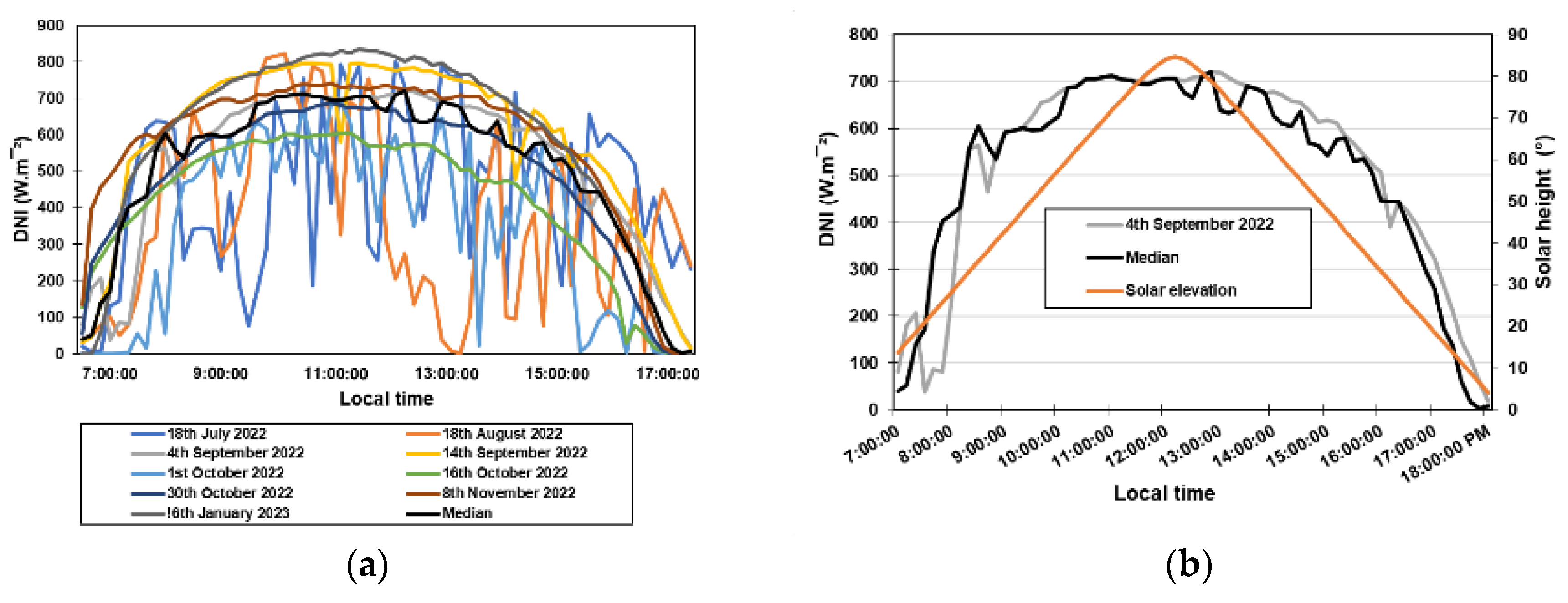
Figure 3a,b illustrate the DNI from 6 July 2022 to February 2023 for some days. For all the days, the DNI increases from a lower value at 7:20 to a maximum value at around 13:00 and decreases to a lower value around 18:00. After the analysis of the collected data based on median computation, the 4th of September 2022 (Figure 3b) was more representative with DNI profile fitting with the median values.

3.2.2. The Effect of Mass Flow Rate on Collector Performance

To assess the effect of mass flow ( m ˙ H T F ) on the PTC performance, a module with 7.8 m length and 5 m width (around 39 m2 of collection area) was considered. The m ˙ H T F is an important parameter for CSP designing. It is related to the saturated steam flow rate generation in the boiler and can be computed from a steady-state energy balance [12] using Equation (11):
m ˙ H T F C p , H T F T H T F , i n T H T F , o u t = m ˙ s t e a m × H f g
C p , H T F is the HTF specific heat capacity, T H T F , i n the HTF inlet temperature in the boiler from the solar field or TES system. T H T F , o u t the HTF outlet temperature from the boiler, m ˙ s t e a m the steam flow and H f g the enthalpy of vaporization of the working fluid.
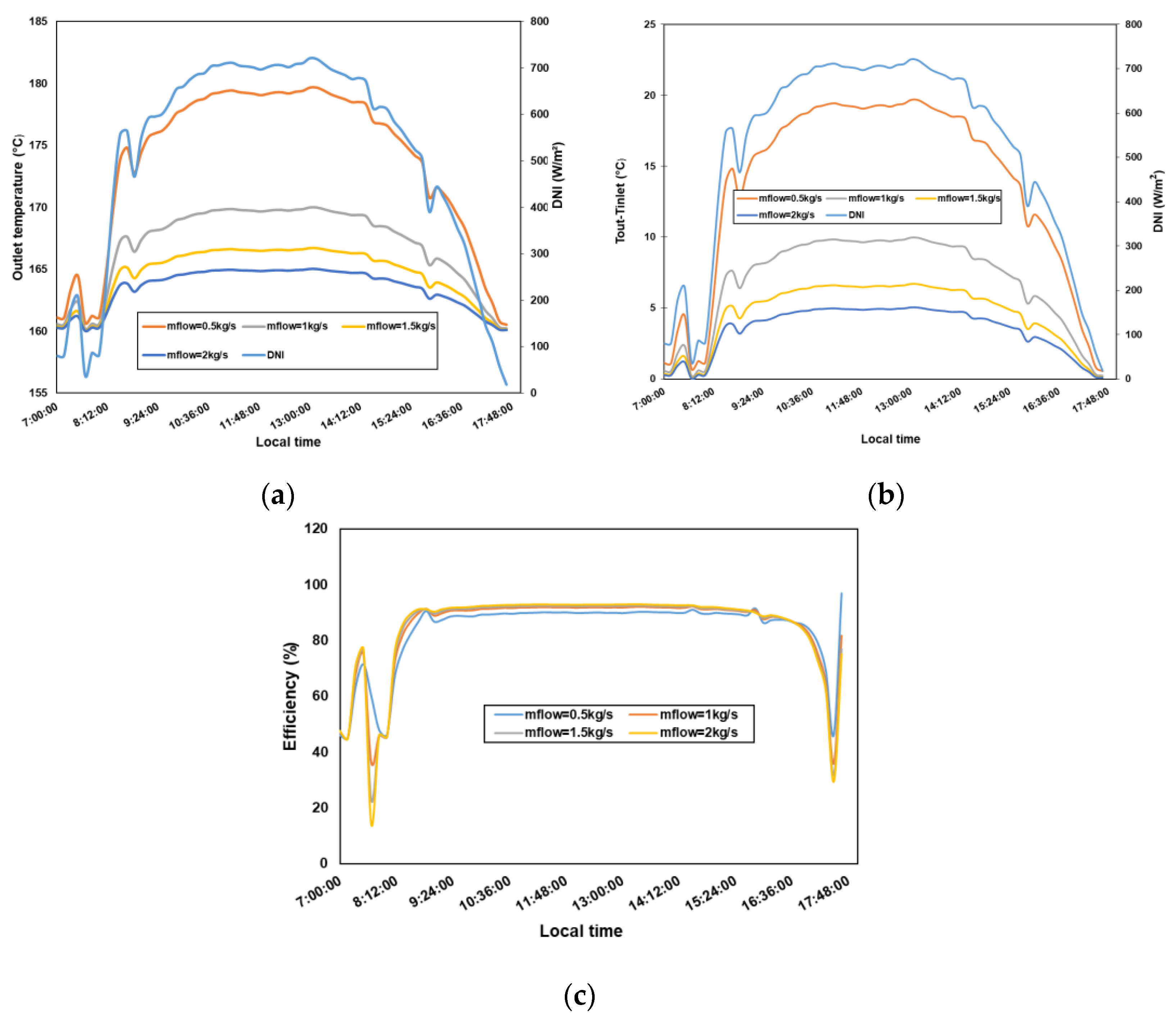
Figure 4a–c illustrates, respectively, the effect of JCO mass flow on its outlet ( T o u t ) and difference temperature ( T ) and the instantaneous efficiency ( η i n s t ) of the PTC. The results show that whatever the mass flow rate the ( T o u t ) (Figure 4a) and T (Figure 4b) increase with sun radiation, reach a maximum value at the zenith, and decrease when the DNI decreases. This shows that T o u t and T depend highly on DNI. The higher the DNI, the higher the heat gain by the JCO and the higher are T o u t and T . Depending on the mass flow rate, the heat effect will be difference driving at different T o u t and T . So, the lower the mass flow rate is, the higher T o u t and T are. However, there is a low effect of m ˙ H T F on the PTC thermal efficiency (Figure 4c); a slight increase is observed when the mass flow rate increases. A better outlet and different temperature (maximum values of T o u t   = 179.667 °C and T = 19.667 °C at 13:10 min) are achieved at low mass flow leading to the increasing heat loss because the lowest average η i n s t is 83.77%     16.66 % for a mass flow rate of 0.5 kg s−1 against 84.56% for a mass flow rate of 2 kg s−1.

3.2.3. The Effect of Collector Length Rate on Collector Performance

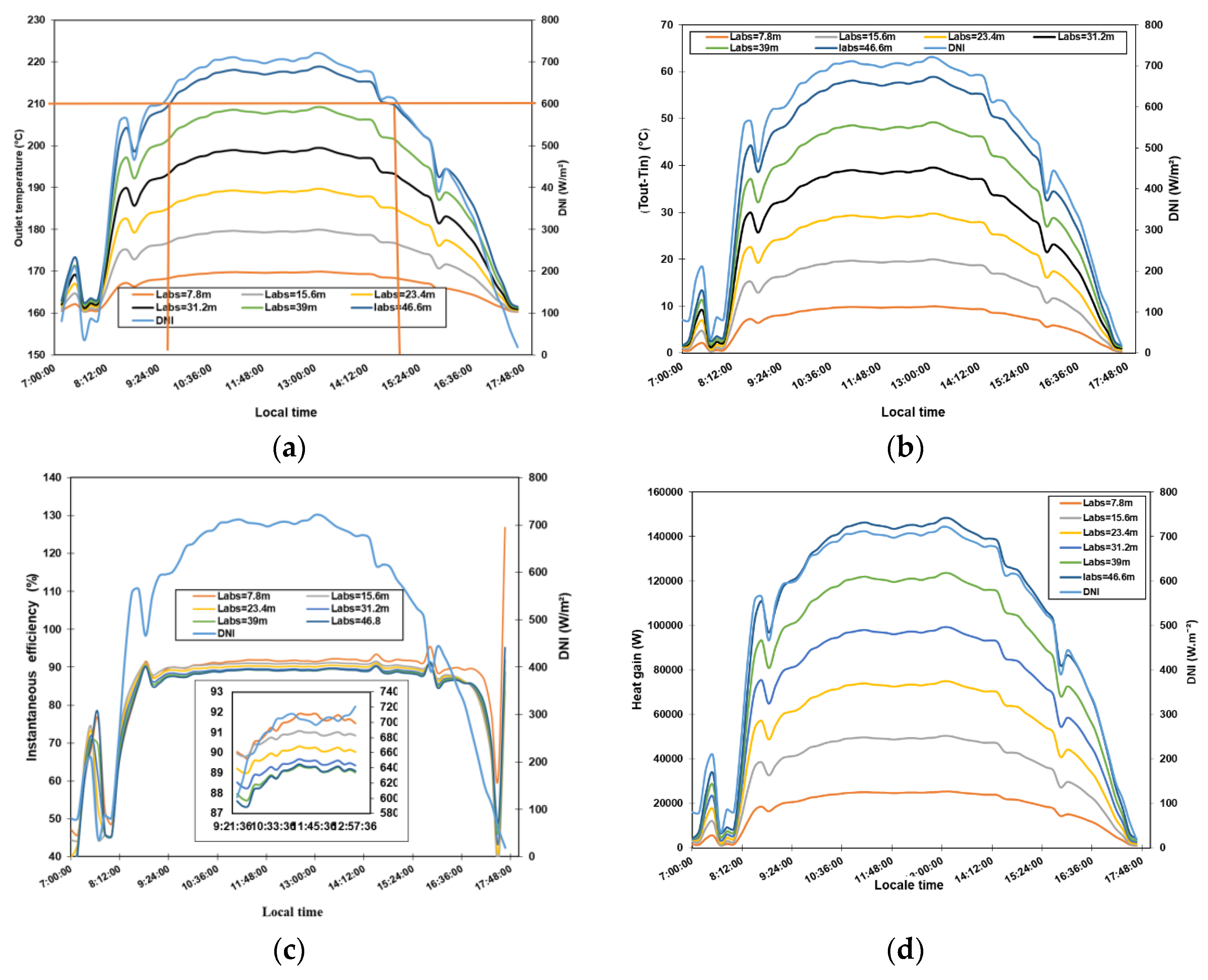
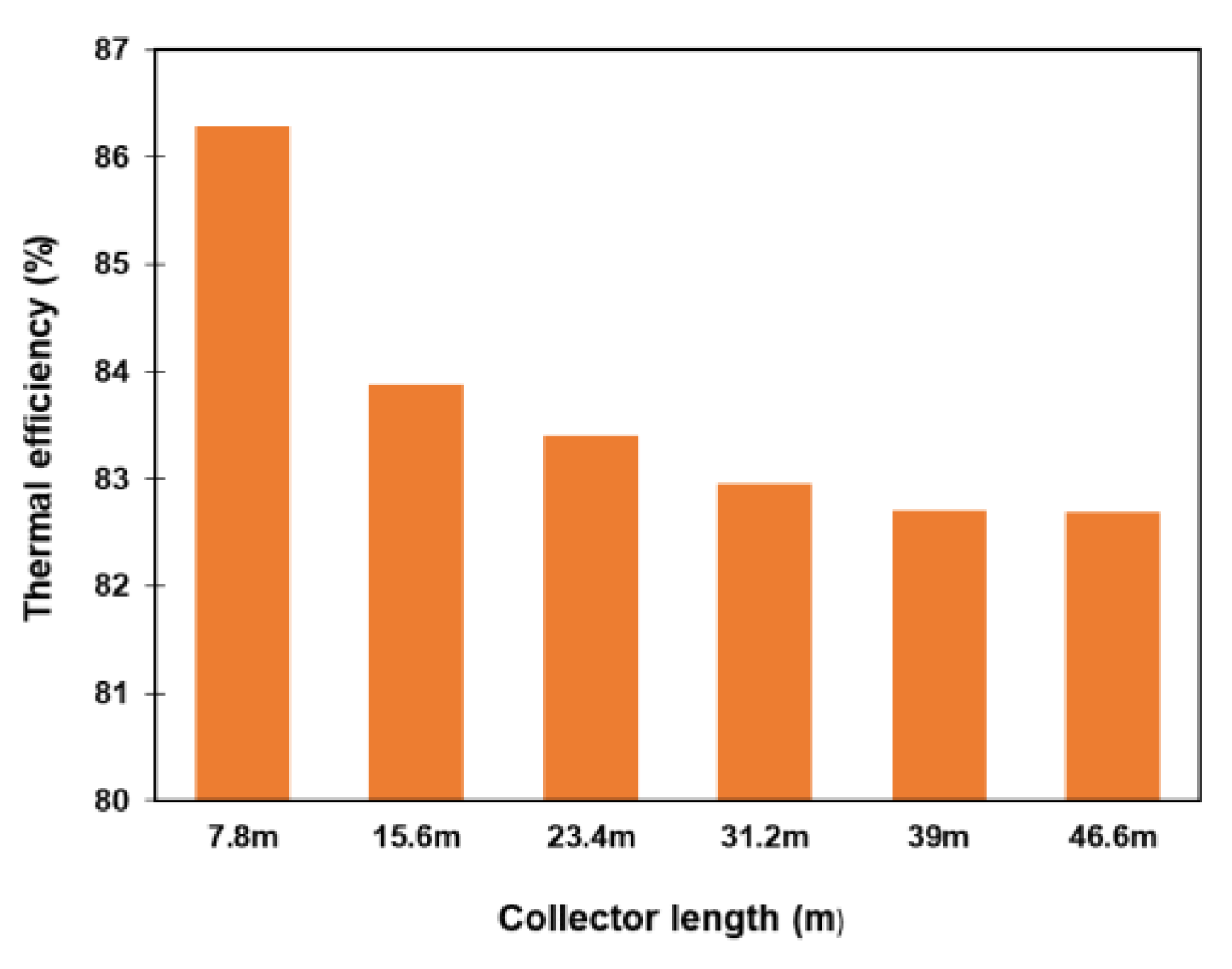
From the assessment of the outlet temperature with one collector module, no mass flow was allowed to reach the desirable T o u t (210 °C). In addition, for a demonstration PTC plant, the mass flow should reach about 1 kg s−1 [13]. So, in this study, a mass flow rate of at least 1 kg s−1 and inlet temperature of 160 °C are considered in this section. With a mass flow of 1 kg s−1, the outlet HTF temperature is less than 210 °C To handle this issue, the solution is to put the collector’s module in series by increasing the PTC collection area. Figure 5a–d illustrate the effect of absorber length or collector size on the JCO T o u t , T , η i n s t and heat gain by the HTF. T o u t and T increases when the collector length increases (Figure 5a,b). The results show that a collection area of 230 m2 is needed to achieve 210 °C as T o u t . A maximum T o u t of 218.8 °C can be reached at 13:20 min (Figure 5a) with maximal, T of 58.8 °C (Figure 5b). Thus, the increase in collector length or area led to an increase in the heat gain (Figure 5d) by the fluid. Considering the PTC thermal efficiency as illustrated in Figure 5c, it increases when the DNI increases whatever the collector length and reaches a maximum value at 9:00 remains constant till around 15:30 and decreases to 40%. Due to DNI fluctuation, unreasonable transient evaluation such as more than 100% instantaneous efficiency is observed between 17:30 and 18:00. This is due to the DNI fluctuation [14]. It can be observed that the η i n s t decreases when the collector size increases. For the average η t h , it decreases from 86.28% to 82.69% when the collector length increases from 7.8 m to 46.8 m (Figure 6).

4. Conclusions

In this work, a model has been developed for dynamic performance analysis of a PTC under Ouagadougou climate conditions. The model was validated with a maximum relative error of 8.08%. The DNI data collected with the weather station show that the 4th of September was the more representative day for the PTC performance analysis. The effect of mass flow rate shows that a low mass flow rate increases the outlet temperature driving the decrease in thermal efficiency. Also, for the collector length effect on the PTC performance (efficiency) with a mass flow rate of 1 kgs−1, more heat losses are observed at longer collector length leading to a reduction in instantaneous efficiency. This is due to the increase in outlet temperature. In conclusion, the increase in JCO temperature leads to more heat losses in the PTC. For a mass flow of 1 kg s−1, a collector length of 46.8m is required to obtain an outlet temperature of about 210 °C within the day.

Author Contributions

Conceptualization, B.B., M.B., T.D. and I.K.M.; methodology, B.B.; software, B.B.; validation, B.B., M.B., T.D. and I.K.M.; formal analysis, B.B.; investigation, B.B.; resources, B.B., M.B., T.D., I.K.M., Y.W.G. and A.B.; data curation, B.B., S.Z.K., K.A., Y.W.G. and A.B.; writing—original draft preparation, B.B.; writing—review and editing, I.K.M., S.Z.K. and H.S.D.N.; supervision, M.B., T.D. and I.K.M.; project administration, M.B.; funding acquisition, B.B. All authors have read and agreed to the published version of the manuscript.

Funding

The data collection station and the conference fees were funded by Cuomo Foundation and IPCC.

Institutional Review Board Statement

Not applicable.

Informed Consent Statement

Not applicable.

Data Availability Statement

The data were collected using a weather station connected to a pyrheliometer and can be provide with the consent of WASCAL and LPCE. The results and the output data from the model and the DNI data of the 4 September are available on request from the corresponding author.

Acknowledgments

This document was produced with financial support from the Intergovernmental Panel on Climate Change (IPCC) Scholarship Program through the fund from the Cuomo Foundation. The contents of this document are solely the liability of Boubou BAGRE and under no circumstances may be considered as a reflection of the position of Cuomo Foundation and/or IPCC.

Conflicts of Interest

The authors declare no conflict of interest.

References

  1. Eltawil, M.A.; Zhengming, Z.; Yuan, L. A review of renewable energy technologies integrated with desalination systems. Renew. Sustain. Energy Rev. 2009, 13, 2245–2262. [Google Scholar] [CrossRef]
  2. Ummadisingu, A.; Soni, M.S. Concentrating solar power—Technology, potential and policy in India. Renew. Sustain. Energy Rev. 2011, 15, 5169–5175. [Google Scholar] [CrossRef]
  3. Boubou, B.; Muritala, I.K.; Makinta, B.; Tizane, D.; Christian, T.G.; Jacques, N.; Téré, D.; Antoine, B. Review on Thermocline Storage Effectiveness for Concentrating Solar Power Plant. Energy Power Eng. 2021, 13, 343–364. [Google Scholar] [CrossRef]
  4. Sattler, J.C.; Caminos, R.A.C.; Atti, V.; Ürlings, N.; Dutta, S.; Ruiz, V.; Kalogirou, S.; Ktistis, P.; Agathokleous, R.; Alexopoulos, S.; et al. Dynamic simulation tool for a performance evaluation and sensitivity study of a parabolic trough collector system with concrete thermal energy storage. AIP Conf. Proc. 2020, 2303, 160004. [Google Scholar] [CrossRef]
  5. Vignarooban, K.; Xu, X.; Arvay, A.; Hsu, K.; Kannan, A.M. Heat transfer fluids for concentrating solar power systems—A review. Appl. Energy 2015, 146, 383–396. [Google Scholar] [CrossRef]
  6. Padilla, R.V.; Demirkaya, G.; Goswami, D.Y.; Stefanakos, E.; Rahman, M.M. Heat transfer analysis of parabolic trough solar receiver. Appl. Energy 2011, 88, 5097–5110. [Google Scholar] [CrossRef]
  7. Babikir, M.H.; Njomo, D.; Barka, M.; Chara-dackou, V.S.; Kondji, Y.S.; Khayal, M.Y. Thermal modeling of a parabolic trough collector in a quasi-steady state regime Thermal modeling of a parabolic trough collector in a quasi-steady state regime. J. Renew. Sustain. Energy 2021, 13, 013703. [Google Scholar] [CrossRef]
  8. Haro, K.; Ouarma, I.; Sanogo, O.; Abdoulaye, C.; Tubreoumya, G.C.; Nana, B.; Bere, A.; Koulidiati, J. Evaluation de l’empreinte carbone d’une Installation de Stockage des Déchets Non Dangereux (ISDND): Cas du centre traitement et de valorisation des déchets (CTVD) sis à Polesgo (Ouagadougou). J. Phys. Soaphys 2019, 1, C19A5-1–C19A5-5. [Google Scholar] [CrossRef]
  9. Haro, K.; Ouarma, I.; Nana, B.; Bere, A.; Tubreoumya, G.C.; Kam, S.Z.; Laville, P.; Loubet, B.; Koulidiati, J. Assessment of CH4 and CO2 surface emissions from Polesgo’s landfill (Ouagadougou, Burkina Faso) based on static chamber method. Adv. Clim. Chang. Res. 2019, 10, 181–191. [Google Scholar] [CrossRef]
  10. Dudley, V.E.; Kolb, G.J.; Mahoney, A.R.; Mancini, T.R.; Matthews, C.W.; Sloan, M.; Kearney, D. Test Results: SEGS LS-2 Solar Collector; Report: SAND94-1884; Sandia National Laboratory: Albuquerque, Mexico, 1994; Volume 140. [Google Scholar]
  11. Bagré, B.; Boukar, M.; Muritala, I.K.; Mortey, E.M.; Ouarma, I.; Tera, S.; Korsaga, A.; Rabani, A. Modelling and Simulation of a Sustainable Thermal Energy Storage System for Concentrating Solar Power (CSP) Plant Using Eco-Materials. JP J. Heat Mass Transf. 2023, 31, 147–161. [Google Scholar] [CrossRef]
  12. Powell, K.M.; Edgar, T.F. Modeling and control of a solar thermal power plant with thermal energy storage. Chem. Eng. Sci. 2012, 71, 138–145. [Google Scholar] [CrossRef]
  13. Visser, C.J.; Malan, P.A.G.; Meyer, P.J.P. Modelling Heat And Mass Flow Through Packed Pebble Beds: A Heterogeneous Volume-Averaged Approach. Doctoral Dissertation, University of Pretoria, Pretoria, South Africa, 2008. [Google Scholar]
  14. Xu, C.; Wang, Z.; He, Y.; Li, X.; Bai, F. Sensitivity analysis of the numerical study on the thermal performance of a packed-bed molten salt thermocline thermal storage system. Appl. Energy 2012, 92, 65–75. [Google Scholar] [CrossRef]
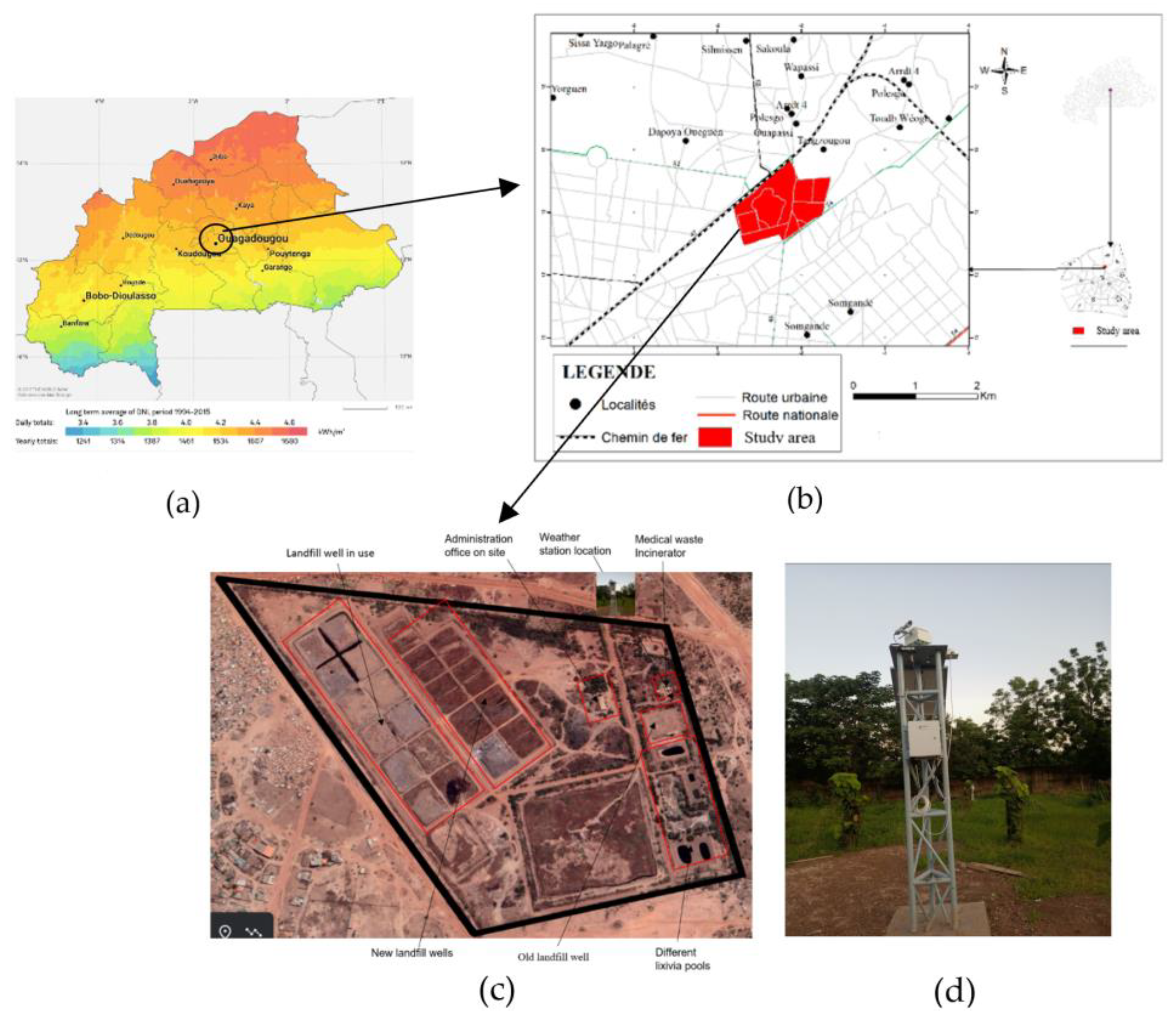
Figure 2. DNI map of Burkina Faso (a), landfill location in Ouagadougou city (b), top view of study area (c), weather station used for data collection (d).
Materproc 11 00006 g002
Figure 3. DNI data was collected at Polesgo for some days using the weather station (a), DNI, and solar elevation data of the 4th of September 2022 (b).
Materproc 11 00006 g003
Figure 4. Effect of JCO mass flow on its outlet (a) and difference (b) temperature profile and Instantaneous thermal efficiency (c).
Materproc 11 00006 g004
Figure 5. Effect of the collector length on JCO outlet temperature (a), JCO temperature difference (b), PTC Instantaneous efficiency (c) and JCO heat gain (d).
Materproc 11 00006 g005
Figure 6. Effect of the collector length on PTC average efficiency.
Materproc 11 00006 g006
Table 2. Boundary and initial conditions.
Boundary ConditionsInitial Conditions
T f x = 0 = T L (4) T f t = 0 = T a b s = 160   ° C (5)
T f x x = 0 = T a b s x x = 0 = 0 (6) T g l a s s t = 0 = T a m b i e n t (7)
Hot heat transfer fluid leaves the collector, an adiabatic condition for the fluid.
T f x x = L a b s = T a b s x x = L a b s = T g l a s s x x = L g l a s s = 0
(8)If DNI is less than the minimum sunshine value to heat up the fluid, the outlet temperature is less than T i n l e t
Table 3. Comparison of the experimental [10] and simulated outlet temperature to the new model.
CaseDNI (W m−2) m ˙ f   k g   s 1 T i n l e t (°C) T o u t (°C) Δ T (Model) Δ T (Exp)Model Error (°C)
1937.90.6206297.8317.4619.6619.12.932
2933.370.678102.2122.23720.03721.88.087
3920.90.5457379.5397.117.618.54.86
4880.60.6205299317.2718.2718.20.38
5909.50.6580250.7270.519.818.75.88
6968.20.6536151173.3522.3522.30.224
7982.30.6350197.5219.722.2220.91
Disclaimer/Publisher’s Note: The statements, opinions and data contained in all publications are solely those of the individual author(s) and contributor(s) and not of MDPI and/or the editor(s). MDPI and/or the editor(s) disclaim responsibility for any injury to people or property resulting from any ideas, methods, instructions or products referred to in the content.