Proceeding Paper

Electrospun Nanofibers for Optimized Fiber-Shaped Wearable Sensors †

by
Giulia Massaglia
1,2,* and
Marzia Quaglio
1,2,*
1
Department of Applied Science and Technology, Politecnico di Torino, Corso Duca degli Abruzzi 24, 10129 Torino, Italy
2
Center for Sustainable Future and Technologies, CSFT@Polito, Istituto Italiano di Tecnologia, Via Livorno 60, 10100 Torino, Italy
*
Authors to whom correspondence should be addressed.
Presented at the 4th International Online Conference on Nanomaterials, 5–19 May 2023; Available online: https://iocn2023.sciforum.net.
Mater. Proc. 2023, 14(1), 55; https://doi.org/10.3390/IOCN2023-14533
Published: 5 May 2023
(This article belongs to the Proceedings of The 4th International Online Conference on Nanomaterials)

Abstract

:
This work discusses the design of highly stretchable, piezoresistive, flexible sensors obtained by electrospun nanofibers collected on rotating flexible wires. The resulting nanostructured sensors have a fiber-shape due to the inner plastic core being in intimate contact with the nanofibers forming the outer shell. The final fiber-shape thus facilitates the integration of the sensor into soft electronic platforms. Composite nanofibers, made of polyethylene oxide and multiwall carbon nanotubes, were selected as the sensitive material that is able to combine an effective response to mechanical deformation with compatibility in contact with the human body. Two flexible wire collectors were selected: a plastic wire and a plastic hollow wire. We demonstrate that the collectors induce a partially ordered distribution of NFs with good percolation behavior. Piezoresistive characterization confirmed the increase in the nanofibers’ electrical resistance with increasing applied pressure. The dimensionless sensitivity |∆R/R0| was calculated and plotted as a function of the applied pressure, demonstrating the good behavior of the new fiber-shaped pressure sensors.

1. Introduction

The development and design of wearable electronic systems are required to satisfy several requirements, such as real-time detection and the capability to recognize different movements of the human body. For this purpose, flexible and stretchable strain/pressure sensors have attracted significant interest [1,2]. The performance of sensors is strictly correlated with material selection, which must satisfy a complex set of requirements: stretchability, biocompatibility, adaptability, and cheapness. Several works in the literature have proposed sensors characterized by good sensitivity, and, at the same time, many limitations have been raised, mainly that they are addicted to low flexibility and mechanical properties; therefore, there is a necessity to develop sensitive nanostructured materials that are capable of overcoming all the described limitations [3]. To satisfy all features, we propose electrospun nanofibers as sensitive elements, since they, thanks to their intrinsic properties, allow the design of flexible sensors with increased electrical and mechanical performances [4,5,6]. We proposed composite polyethylene oxide/multiwall carbon nanotube (PEO/MWCNTs) nanofibers as the sensitive materials [2]. We investigated two different rotating collectors to obtain fiber-shaped nanomaterials, which were suitable to integrate as wearable sensors [7,8]. The first collector was a non-conductive wire, and the second one was an insulator hollow wire, both made of highly deformable plastic materials. We demonstrate that both collectors induce an ordered distribution of NFs with respect to randomly distributed nanofiber mats in a planar configuration. At the same time, we found that the fiber-shaped sensor exhibits percolation behavior in line with that of its planar counterparts [9]. Concerning the piezoresistive performance, we demonstrated good electrical behavior of the nanofibers before and after applied deformations, confirming their complete reliability and reuse as sensitive nanomaterials. The piezoresistive responses confirmed an increase in the nanofibers’ resistance with increasing applied pressure. A dimensionless parameter |∆R/R0| was calculated and plotted as a function of applied pressure to define the sensitivity and resolution of the sensors. All the results highlighted that good sensors’ resolution and sensitivity were achieved when ordered nanofibers were collected onto both wire substrates, thus extending the deformation range to which the sensitive nanomaterial can be subjected. A new flexible pressure sensor is proposed as a device that is directly integrated into textiles.

2. Materials and Methods

2.1. Synthesis of PVDF Nanofibers through Electrospinning Process

A polymeric solution suitable for electrospinning process was prepared by dissolving 5 wt% of PEO (Mw = 600 kDa, purchased from Sigma Aldrich, Saint Louis, MO, USA) in a water-based solution containing polystyrene sulfonate (PSS, purchased from Sigma Aldrich). PSS served as the dispersing agent of MWCNTs, improving their wettability in water. PSS was added with a weight ratio of 1:1 with respect to MWCNTs (from Nanocyl, Sambreville, Belgium). The dispersion was then processed toward probe-type sonication. In order to analyze the percolation behavior, we analyzed and compared nanostructured fiber-shaped sensors made of nanofibers with different compositions, i.e., different MWCNT concentrations. The following values were selected: 1.5, 2.2, 2.5, 3.5, and 5 wt%, with respect to PEO. As largely implemented in our works [5,6,9], all prepared polymeric solutions were loaded into a syringe and electrospinning process was provided (NANON 01A by MECC). In this work, two rotating collectors were used, both made of PE: one was an insulating wire and the second one a hollow wire. Both of two insulating substrates were fixed to the rotating mandrel and an aluminum blade was used to help NF accumulation on the insulating substrate [7]. A rotation speed of 100 rpm was selected.

2.2. Morphological Characterization and Physico-Chemcial Characterizations

Field Emission Scanning Electron Microscopy (FESEM ZEISS SUPRA) was used to analyze the morphology of PEO/MWCNT NF-based fiber-sensors. To perform the electrical characterizations, a multimeter of KEITHLEY 6430 was provided, which was able to polarize all samples by defining a voltage value of 1 V and measure current as function of time.
Piezoresistive analysis was performed applying controlled stress with a laboratory dynamometer by Instron. Fiber-shaped sensors were placed on a PDMS (Sylgard 184, Milano, Italy) slab and deformed while recording I (V) curves at each applied load. The resistance was then indirectly calculated by Ohm’s law to obtain |∆R/R0|. Plotting |∆R/R0| versus the applied load allowed us to evaluate the sensitivity of the sensors.

3. Results and Discussion

3.1. Morphology

Fiber-shaped sensors collected on flexible wires had an average diameter of about 450 μm and a thickness of the NF’s outer layer of about 3 μm. Figure 1a shows the optical image of a fiber-shaped sensor. Details on the NF’s morphology have been gained by FESEM, which allowed appreciating the preferential orientation induced by the composite PEO/MWCNT composite NFS, as depicted in Figure 1b.

3.2. Electrical Characterization

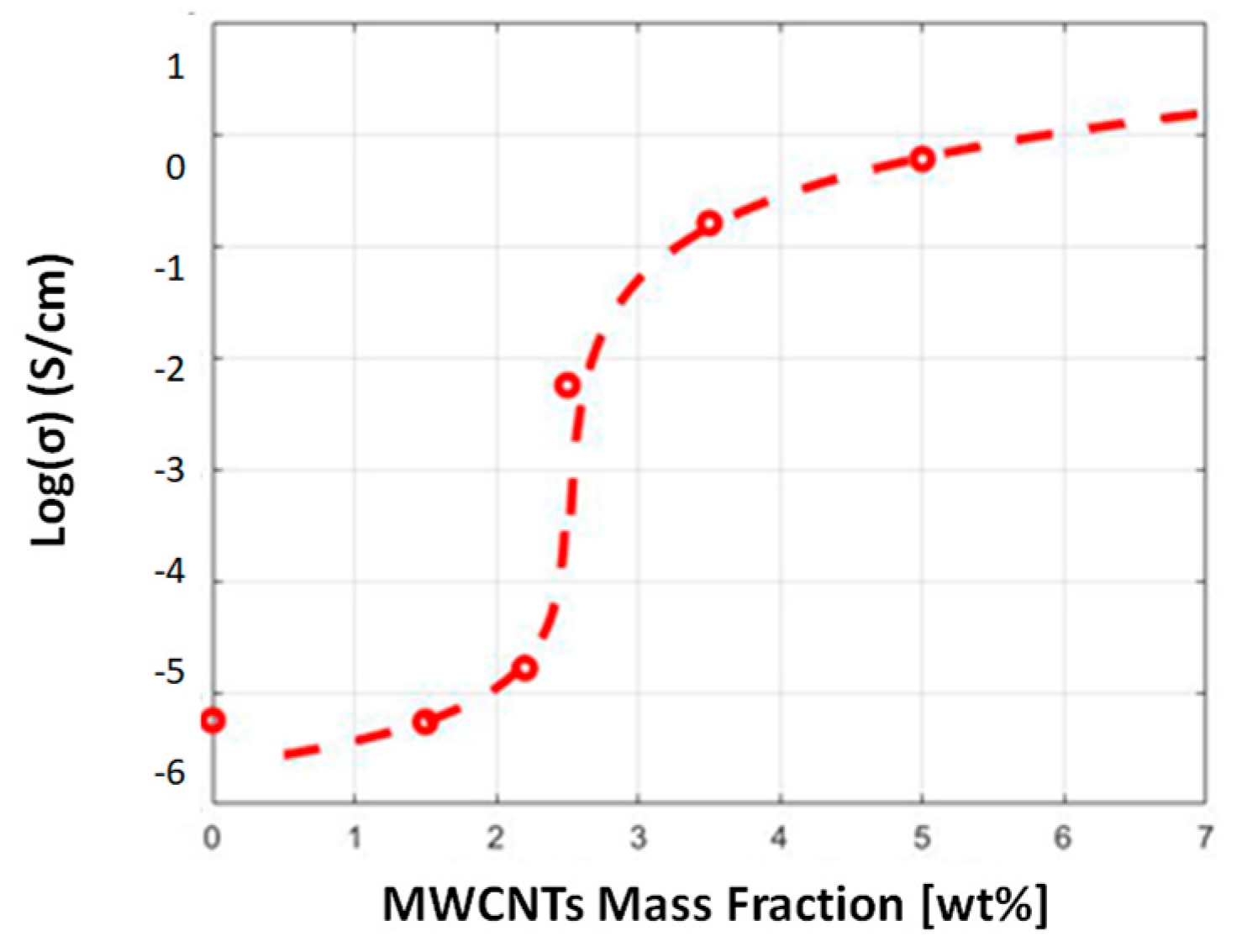
To obtain the percolation curve, we defined the electrical conductivity values that were reached for each amount of MWCNT, as summarized in Table 1.
Starting from the definition of the experimental values of the electrical conductivity (Table 1), we determined the percolation curve of the composite nanomaterials, also defining the trend of the electrical conductivity as a function of the MWCNT weight percentages (Figure 2). As described in detail by Massaglia et al. [9], we implemented the percolation model to fit all the data, thus leading to a description of the electrical conductivity above and below the percolation threshold, defined as an amount of conductive filler in correspondence to which the electrical conductivity increases exponentially.
It was possible to define the percolation threshold value at 2.5 wt% MWCNTs. The higher the amount of nanofibers in i MWCNTs, the higher the electrical properties of composite nanofiber mats. This behavior was addicted to the formation of a conductive network inside the nanostructured polymer matrix, thus leading to an exponential increment of electrical conductivity for all weight percentages of MWCNTs above the percolation one. After the percolation threshold, the curve tended to a stable value of electrical conductivity when the amount of MWNCTs was around 6 wt%. This obtained value of the percolation threshold was higher than that reported in the literature for planar-shaped nanofiber sensors [10]. These latter results can be explained by considering that, in this work, we implemented two collectors, wire and tubular configurations, which induced a more aligned nanofiber assembly (Figure 1b) in comparison with the random distribution obtained when the planar’s counter electrode was used.

3.3. Piezoresistive Characterization

The sensitivity of a piezoresistive pressure sensor can be defined as follows:
S = Δ R / R 0 P
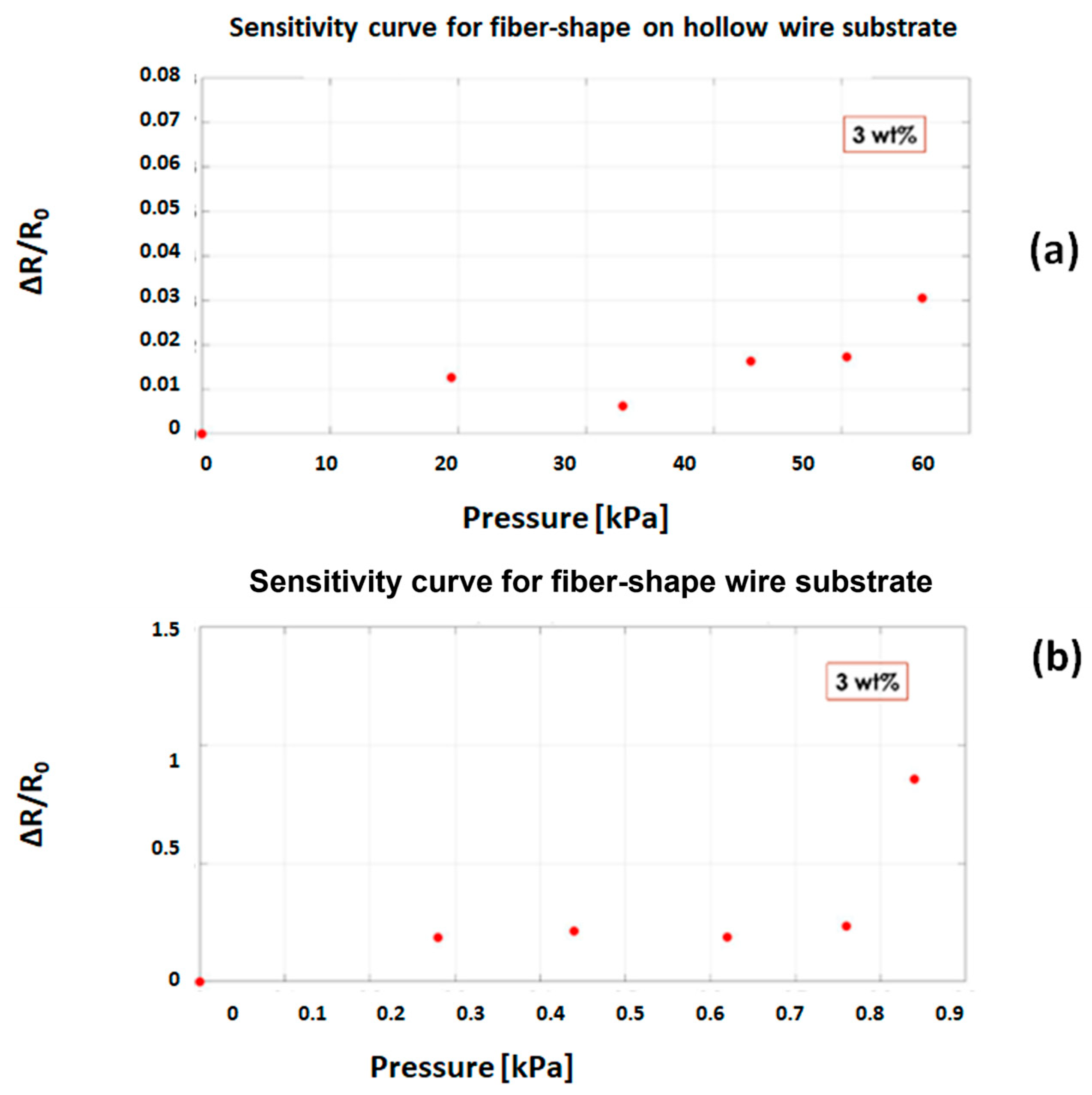
where ΔR/R0 is the variation of electrical resistance induced by an applied pressure P, where the main purpose is to define the sensitivity of fiber-shaped nanostructured sensors, we selected composite nanofibers, which contained 3 wt% of MWCNTs, and compared two different shapes of collectors: wire and tubular counter electrodes. I/V curves were obtained by polarizing all the samples toward the application of a range voltage between −10 V and +10 V and evaluating electrical resistance variations. We applied different pressure value depending on whether the collector was employed: in the interval from 0 kPa to 60 kPa for the tubular collector and between 0 and 0.9 MPa for the wire substrate. We indirectly defined the electrical resistance for each pressure values and subsequently calculated the variation of resistance induced by the pressure, with respect to the inherent resistance of the non-deformed material, ΔR/R0. Figure 3 reported the two plots of ΔR/R0 values for each applied pressure sensor, thus leading to an appreciation of how the trends are comparable with what is reported in the literature [11,12].
It is possible to observe that the trend is similar for the two fiber-shaped types of sensors with the first region of the curve showing a constant value of the sensitivity, followed by the second region, with an increase in the electrical resistance variation for high applied pressure. This trend achieved at high pressure can be explained as a result of the destruction of existing percolation channels, which consequently leads to a change in the electron path and thus to an increase in electrical resistance [12]. It is interesting to observe that the fiber-shaped sensors collected on the wires have a significantly higher sensitivity than those collected on hollow wires. This can be explained considering that the effect of pressure on changing the resistivity is enhanced for fiber-shape sensors with a wire core.

4. Conclusions

The main results obtained from the analysis of the electrospun CNT/polymer composite nanofibers have demonstrated and confirmed their percolative behavior, even though the aligned arrangements of nanofibers, induced by wire and tubular-shaped substrates, were largely different from the random distribution achieved with a planar collector. In addition, by conducting a preliminary analysis of two series of samples with conductive fill weight percentages close to the percolation threshold, a piezoresistive response was observed in accordance with the literature, which allowed the best wire collectors to be identified to improve sensitivity.

Author Contributions

All authors contributed to the conceptualization and organization of the work. G.M.: Main focus on experiments and data analysis. M.Q.: Scientific responsible for the project. All authors have read and agreed to the published version of the manuscript.

Funding

This research received no external funding.

Institutional Review Board Statement

Not applicable.

Informed Consent Statement

Not applicable.

Data Availability Statement

Not applicable.

Conflicts of Interest

The authors declare no conflict of interest.

References

  1. Amjadi, M.; Kyung, K.U.; Park, I.; Sitti, M. Stretchable, Skin-Mountable and Wearable Strain Sensors and Their Potential Applications: A Review. Adv. Funct. Mater. 2016, 26, 1678–1698. [Google Scholar] [CrossRef]
  2. Weng, W.; Chen, P.; He, S.; Sun, X.; Peng, H. Smart electronic textiles. Angew. Chem. Int. Ed. 2016, 55, 6140–6169. [Google Scholar] [CrossRef] [PubMed]
  3. Gong, S.; Cheng, W. One-Dimensional Nanomaterials for Soft Electronics. Adv. Electron. Mater. 2017, 3, 1600314. [Google Scholar] [CrossRef]
  4. Wang, Y.; Yokota, T.; Someya, T. Electrospun nanofiber-based soft electronics. NPG Asia Mater. 2021, 13, 22. [Google Scholar] [CrossRef]
  5. Verpoorten, E.; Massaglia, G.; Ciardelli, G.; Pirri, C.F.; Quaglio, M. Design and optimization of piezoresistive peo/pedot:Pss electrospun nanofibers for wearable flex sensors. Nanomaterials 2020, 10, 2166. [Google Scholar] [CrossRef] [PubMed]
  6. Verpoorten, E.; Massaglia, G.; Pirri, C.F.; Quaglio, M. Electrospun peo/pedot:Pss nanofibers for wearable physiological flex sensors. Sensors 2021, 21, 4110. [Google Scholar] [CrossRef] [PubMed]
  7. Nadaf, A.; Gupta, A.; Hasan, N.; Fauziya Ahmad, S.; Kesharwani, P.; Ahmad, F.J. Recent update on electrospinning and electrospun nanofibers: Current trends and their applications. RSC Adv. 2022, 12, 23808. [Google Scholar] [CrossRef] [PubMed]
  8. Fakharuddin, A.; Li, H.; Di Giacomo, F.; Zhang, T.; Gasparini, N.; Elezzabi, A.Y.; Mohanty, A.; Ramadoss, A.; Ling, J.K.; Soultati, A.; et al. Fiber-Shaped Electronic Devices. Adv. Energy Mater. 2021, 11, 2101443. [Google Scholar] [CrossRef]
  9. Massaglia, G.; Chiodoni, A.; Salvador, G.P.; Delmondo, L.; Munoz-Tabares, J.A.; Bocchini, S.; Sacco, A.; Bianco, S.; Saracco, G.; Quaglio, M. Defining the role of nanonetting in the electrical behaviour of composite nanofiber/nets. RSC Adv. 2017, 7, 38812–38818. [Google Scholar] [CrossRef]
  10. Yuan, H.; Zhou, Q.; Zhang, Y. Electrospun Nanofibers; Elsevier; The Textile Institute; Woodhead Publishing: Cambridge, UK, 2017; pp. 125–147. [Google Scholar]
  11. Fan, Q.; Qin, Z.; Gao, S.; Wu, Y.; Pionteck, J.; Mäder, E.; Zhu, M. The use of a carbon nanotube layer on a polyurethane multifilament substrate for monitoring strains as large as 400%. Carbon 2012, 50, 4085–4092. [Google Scholar] [CrossRef]
  12. Chen, L.; Chen, G.H.; Lu, L. Piezoresistive behavior study on fingersensing silicone rubber/graphite nanosheet nanocomposites. Adv. Funct. Mater. 2007, 17, 898–904. [Google Scholar] [CrossRef]
Figure 1. (a) analysis of fiber-shaped sensor collected on the insulating wire; (b) FESEM analysis shows the ordered distribution induced in nanofibers.
Materproc 14 00055 g001
Figure 2. Percolation curve of electrical conductivity expressed as a function of MWCNT content.
Materproc 14 00055 g002
Figure 3. Piezoelectric characterization of fiber-shaped sensors with a 3 wt% of MWCNTS collected on the flexible insulating hollow wire in (a) and on the flexible insulating wire in (b).
Materproc 14 00055 g003
Table 1. Electrical conductivity values corresponding to different MWCNTs’ content.
wt%σfinal (S/cm)
05.62 × 10⁻⁷
1.55.45 × 10−7
2.21.65 × 10−6
2.55.62 × 10−4
3.51.59 × 10−2
55.96 × 10⁻²
Disclaimer/Publisher’s Note: The statements, opinions and data contained in all publications are solely those of the individual author(s) and contributor(s) and not of MDPI and/or the editor(s). MDPI and/or the editor(s) disclaim responsibility for any injury to people or property resulting from any ideas, methods, instructions or products referred to in the content.