
Parameterized 2D Field Model of a Switched Reluctance Motor


 ,
,  and
and
Abstract
:1. Introduction
- Low production cost;
- High durability and reliability of work;
- Encouraging heat dissipation properties (most heat is generated in the stator);
- Resistance to high temperatures;
- Low power losses generated by the rotor;
- Wide range of rotation speed regulation;
- Large ripple of torque;
- High acoustic noise and vibrations; and
- High costs related to the control system.
- It is fully customizable. There is a vast number of elements that can be changed in order to examine different scenarios.
- It has a versatile tool for checking the motor measurement results and also to improve and optimize various types of motor designs.
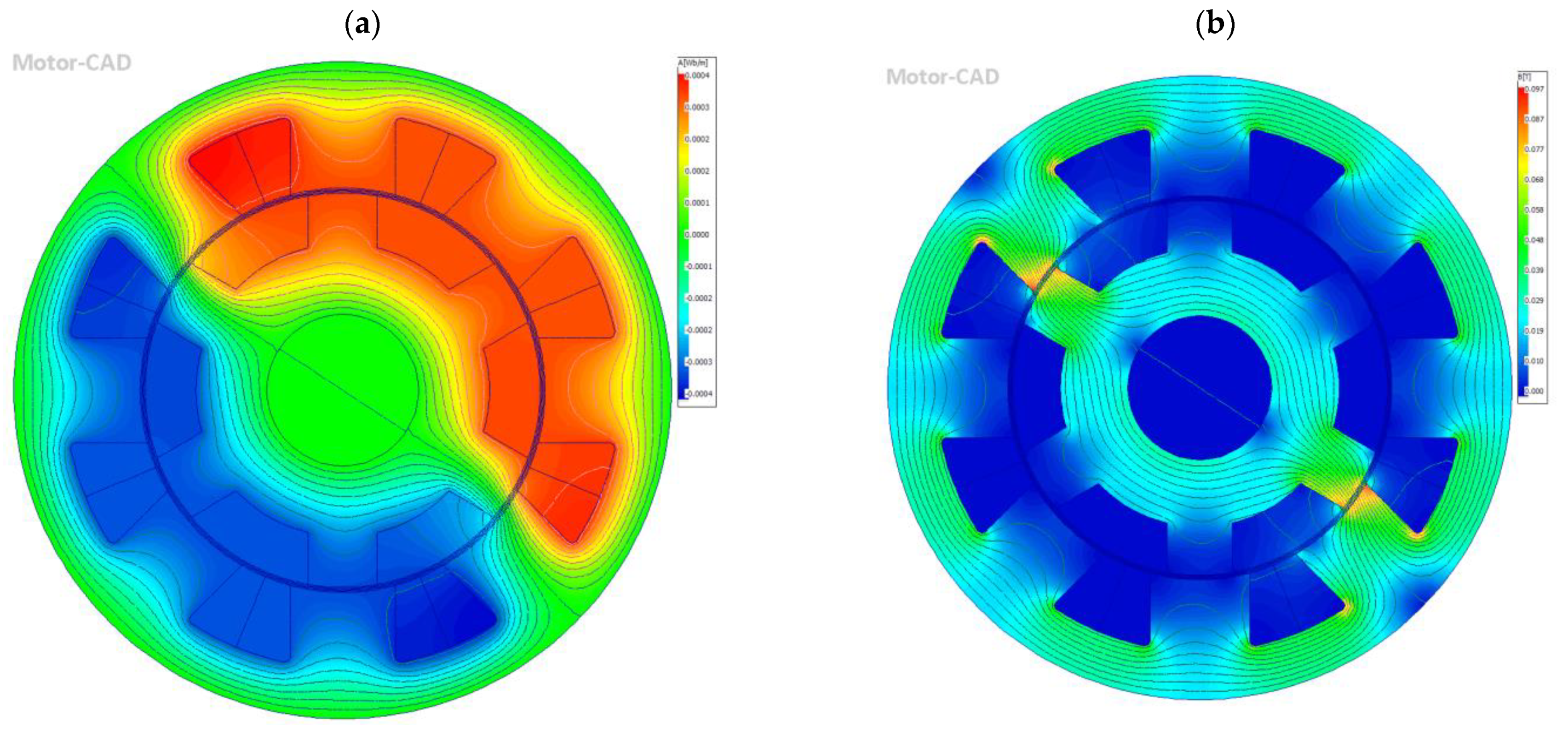
- The didactic feature can be used to observe the distribution of the magnetic flux isolines, the intensity of the magnetic field, or the distribution of the potential in the motor for different variants.
- It is more accurate than analytical calculations; moreover, it is possible to observe the shape of the modelled motor and phenomena occurring during the analysis.
- It can be validated by experimental results derived during work with real-scale SRM motors.
2. State of the Art
3. Theoretical Part
3.1. The Principle of Torque Generation in SRM Motors
3.2. Design Solutions for SRM Motors
- Number of stator poles, Ns;
- Number of rotor poles, Nr; and
- Number of stator winding bands, m.
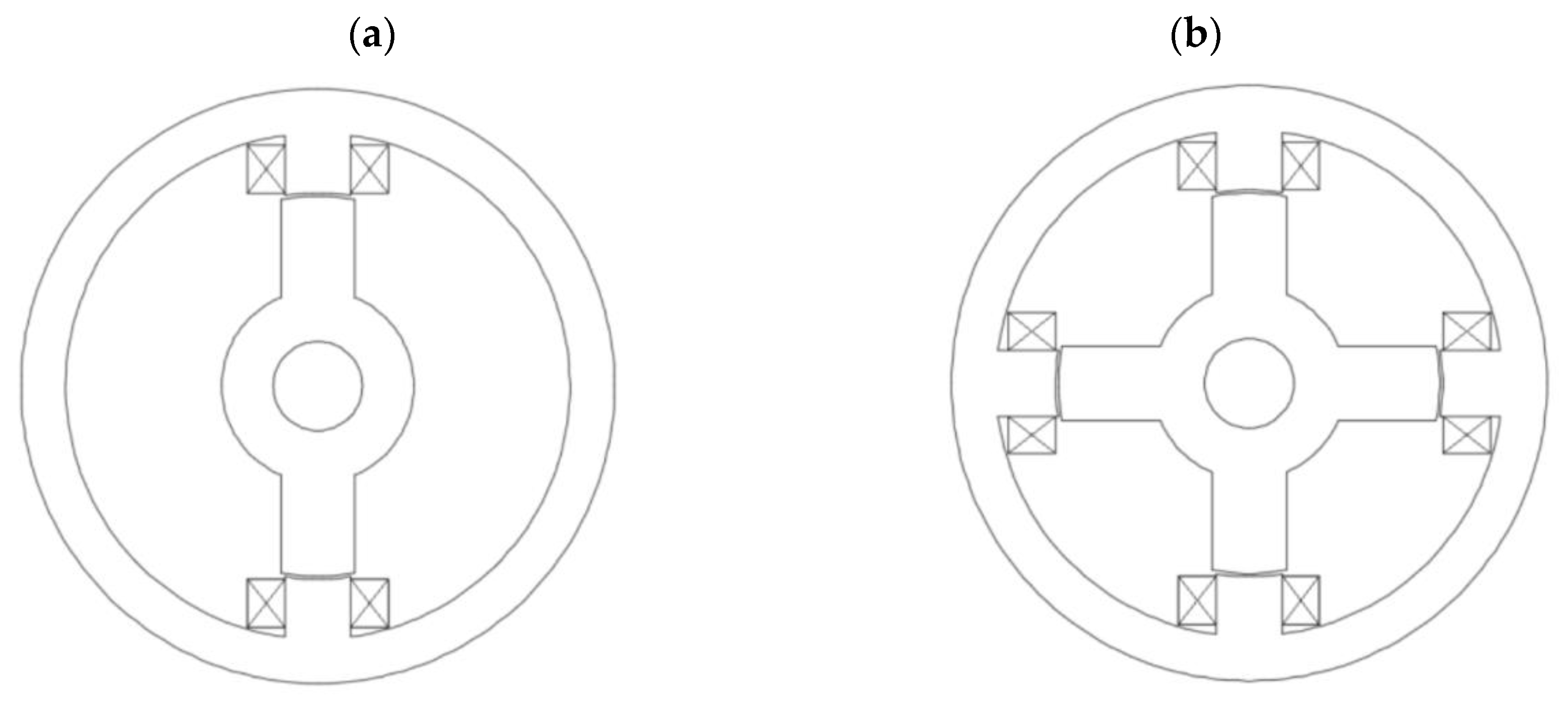
3.2.1. Single-Phase Reluctance Motors
3.2.2. Two-Phase Reluctance Motors
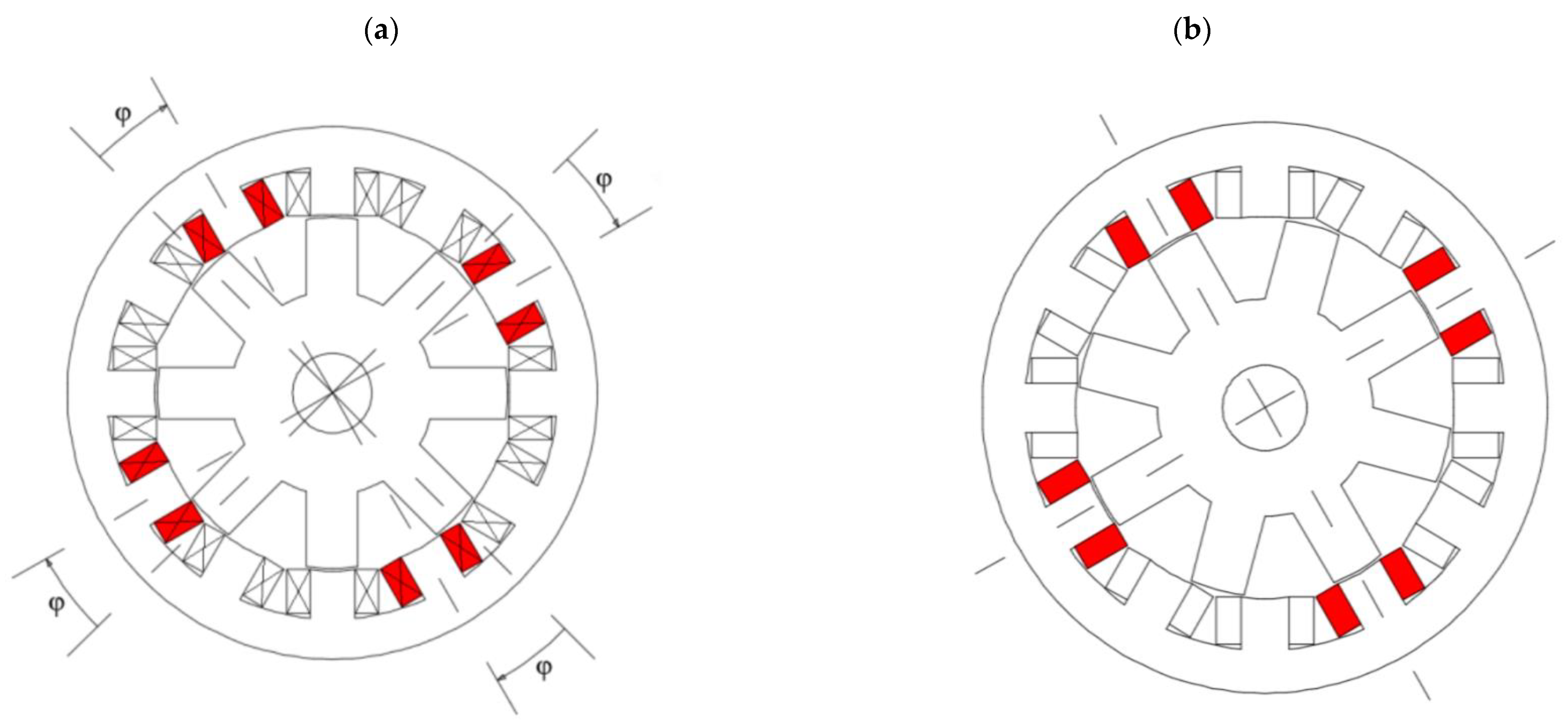
3.2.3. Three-Phase Reluctance Motors
3.2.4. Multi-Phase Reluctance Motors
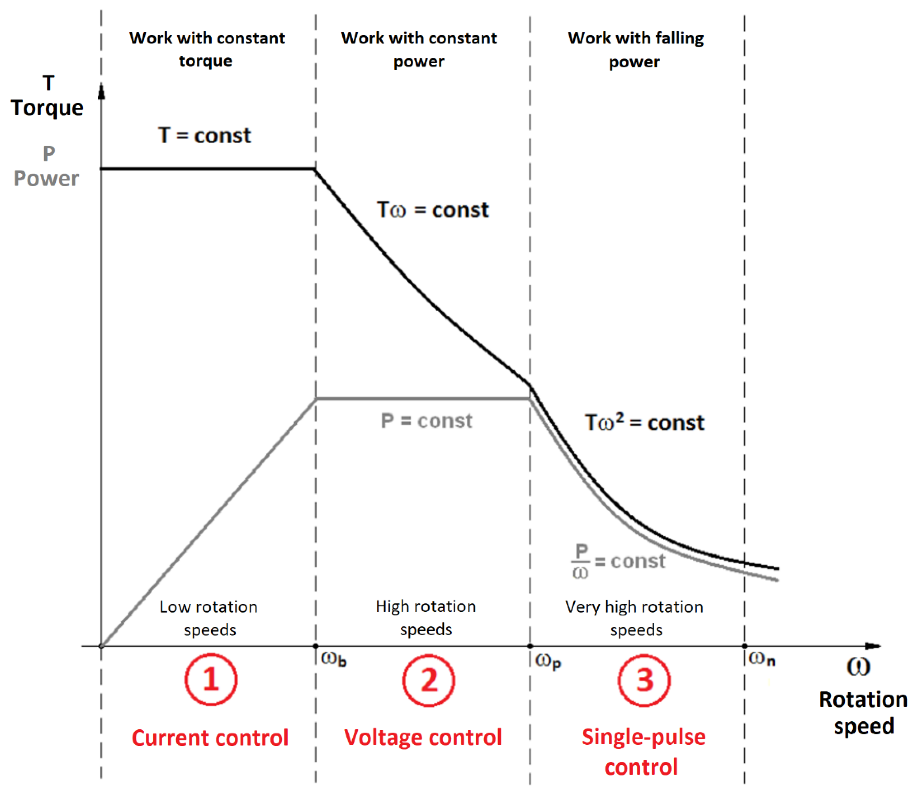
3.3. Control Methods of SRM Motors
- Current control;
- Voltage control;
- Single-pulse control; and
- Direct torque control (theoretically the most difficult control method).
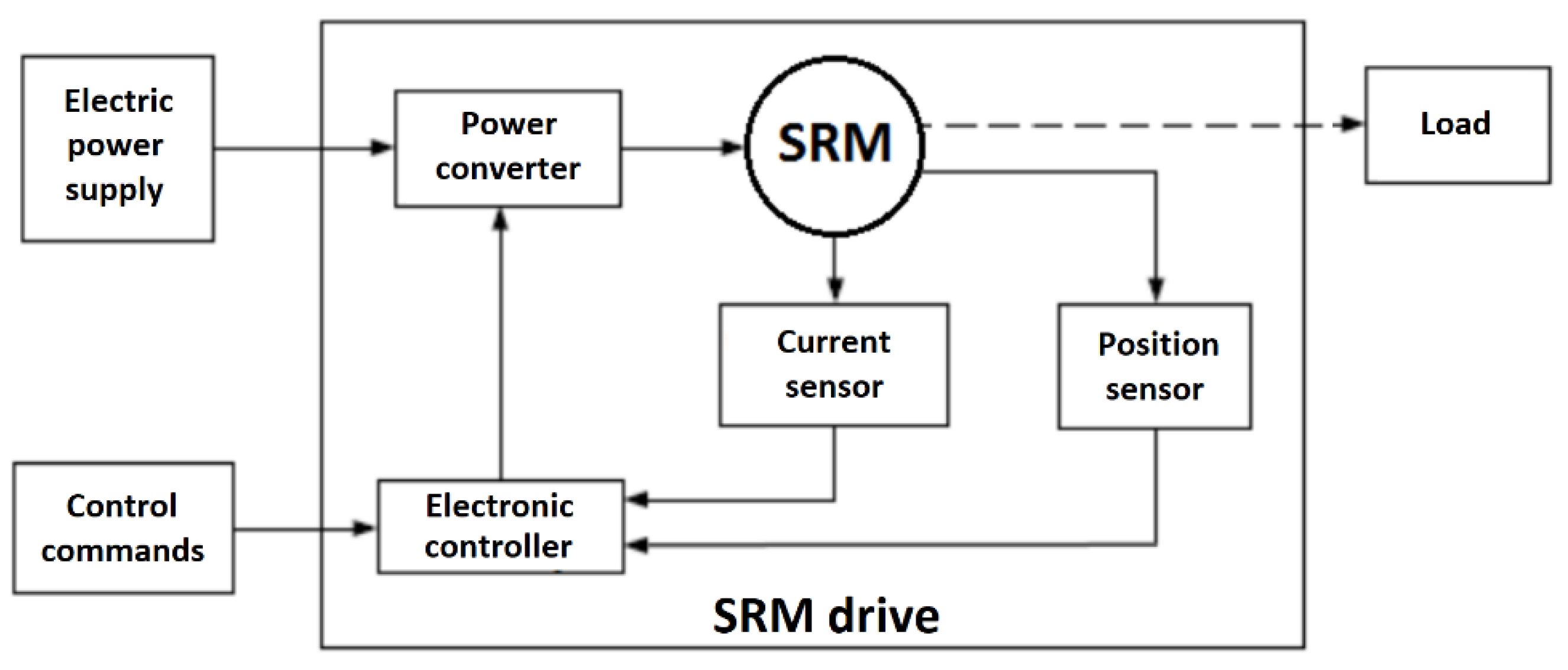
3.3.1. The Operation Principle of the SRM Motor with the Control System
- The angular position sensor of the shaft, e.g., encoder, resolver, or non-contact sensor, that determines the angular position of the shaft/rotor and transmits it to the control system;
- The control system, an electronic system that receives signals from the transducer/angular position sensor that controls the power converter; and
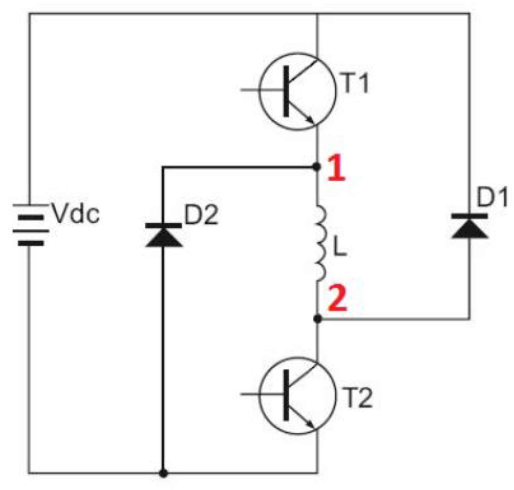
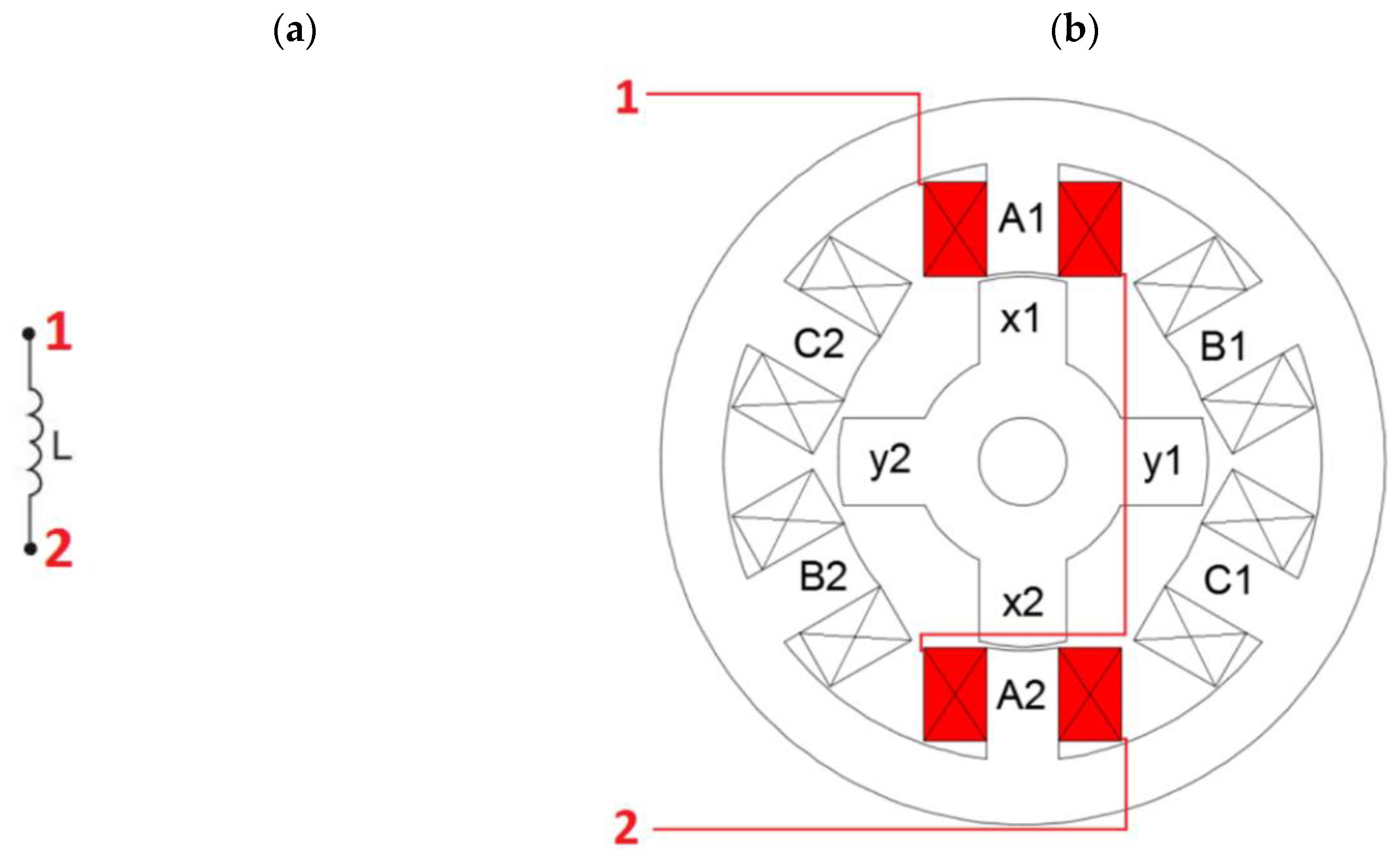
- The power converter, an electronic commutator that switches on the individual phase bands, causing the motor to be in constant motion. The schematic diagram of the converter for one phase band is shown in Figure 8.
3.3.2. Current Control: Constant Torque Operation
3.3.3. Voltage Control: Constant Power Operation
3.3.4. One-Pulse Control: Operation with Falling Power
4. Simulation Part
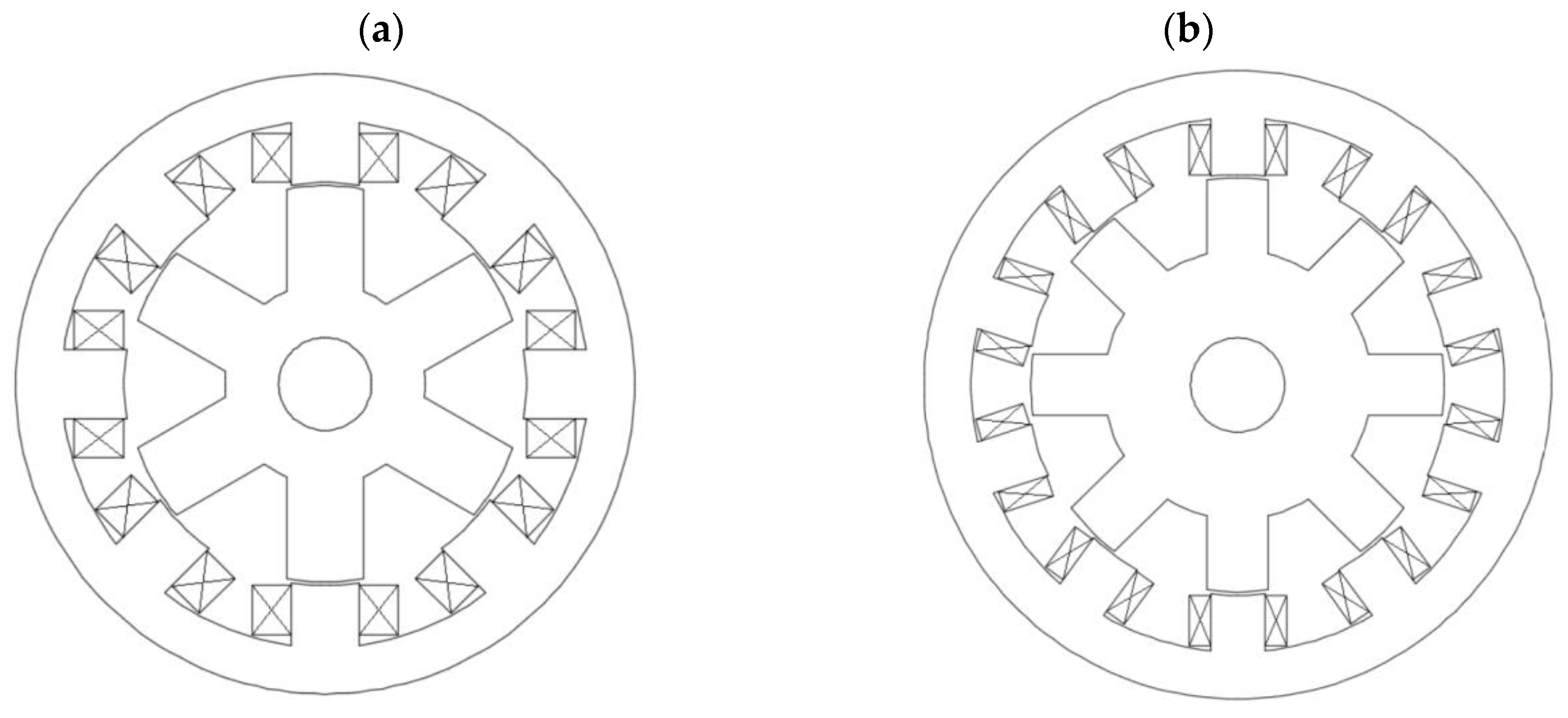
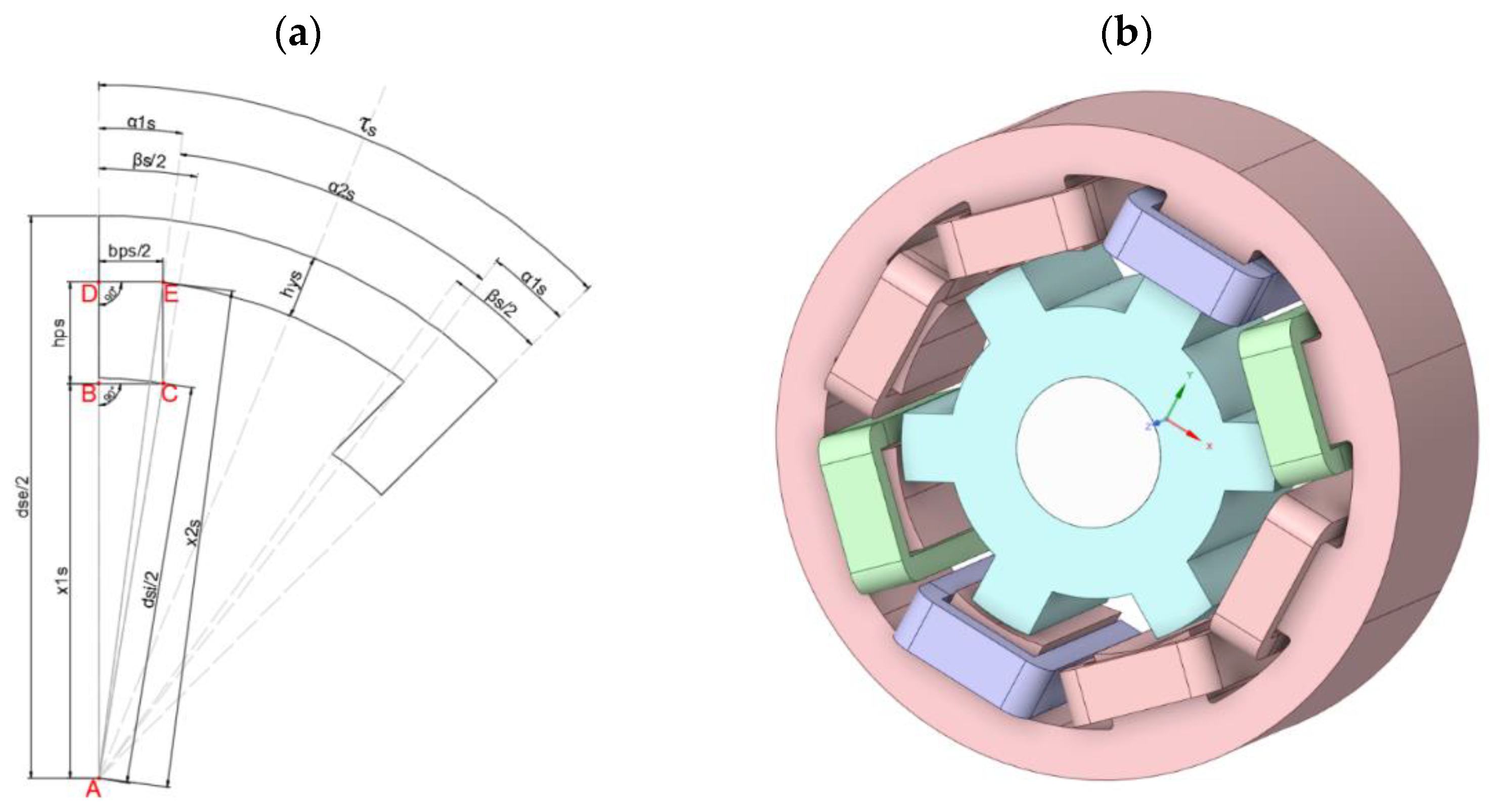
4.1. Model Geometry
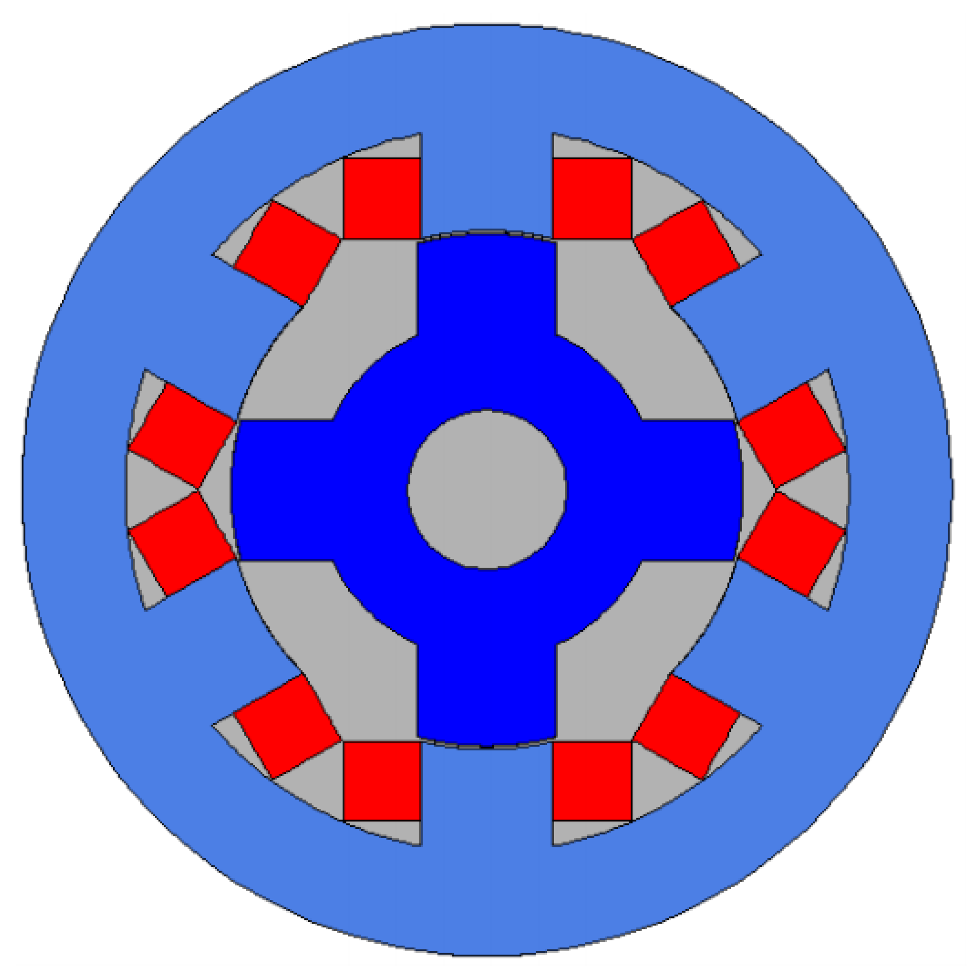
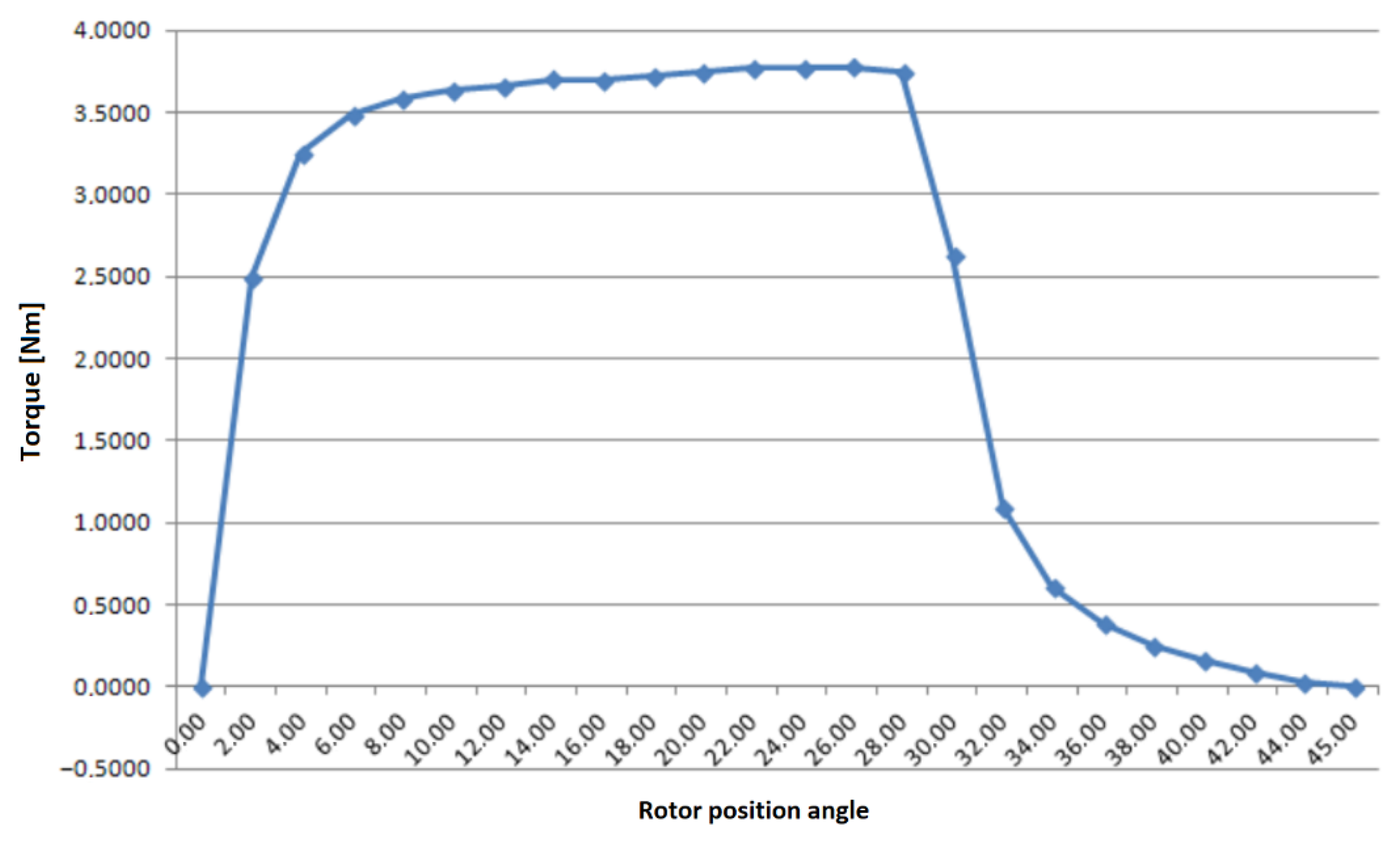
4.2. The 6/4 Motor Simulations’ Results
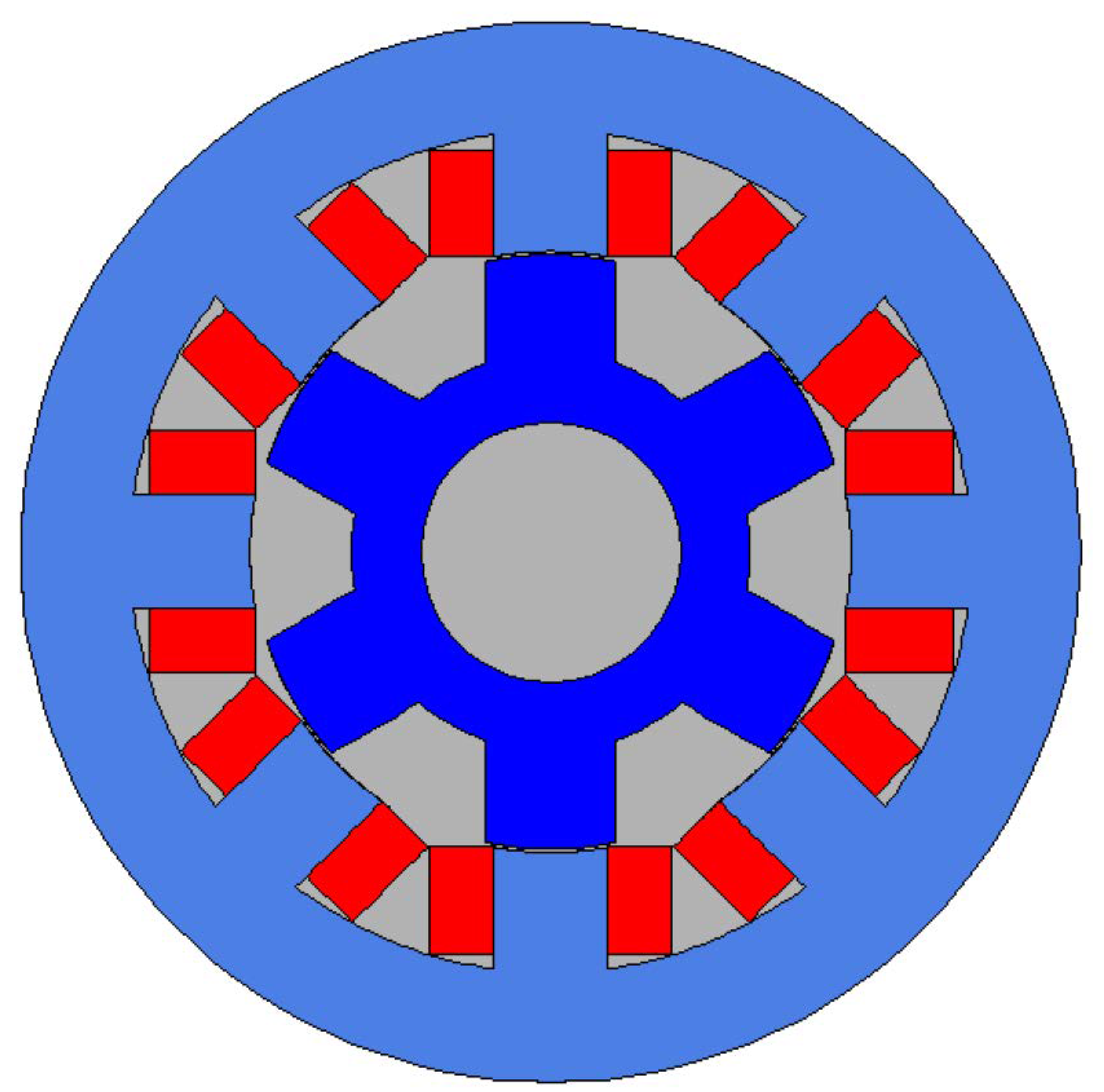
4.3. The 8/6 Motor Simulations’ Results
4.4. The 10/8 Motor Simulations’ Results
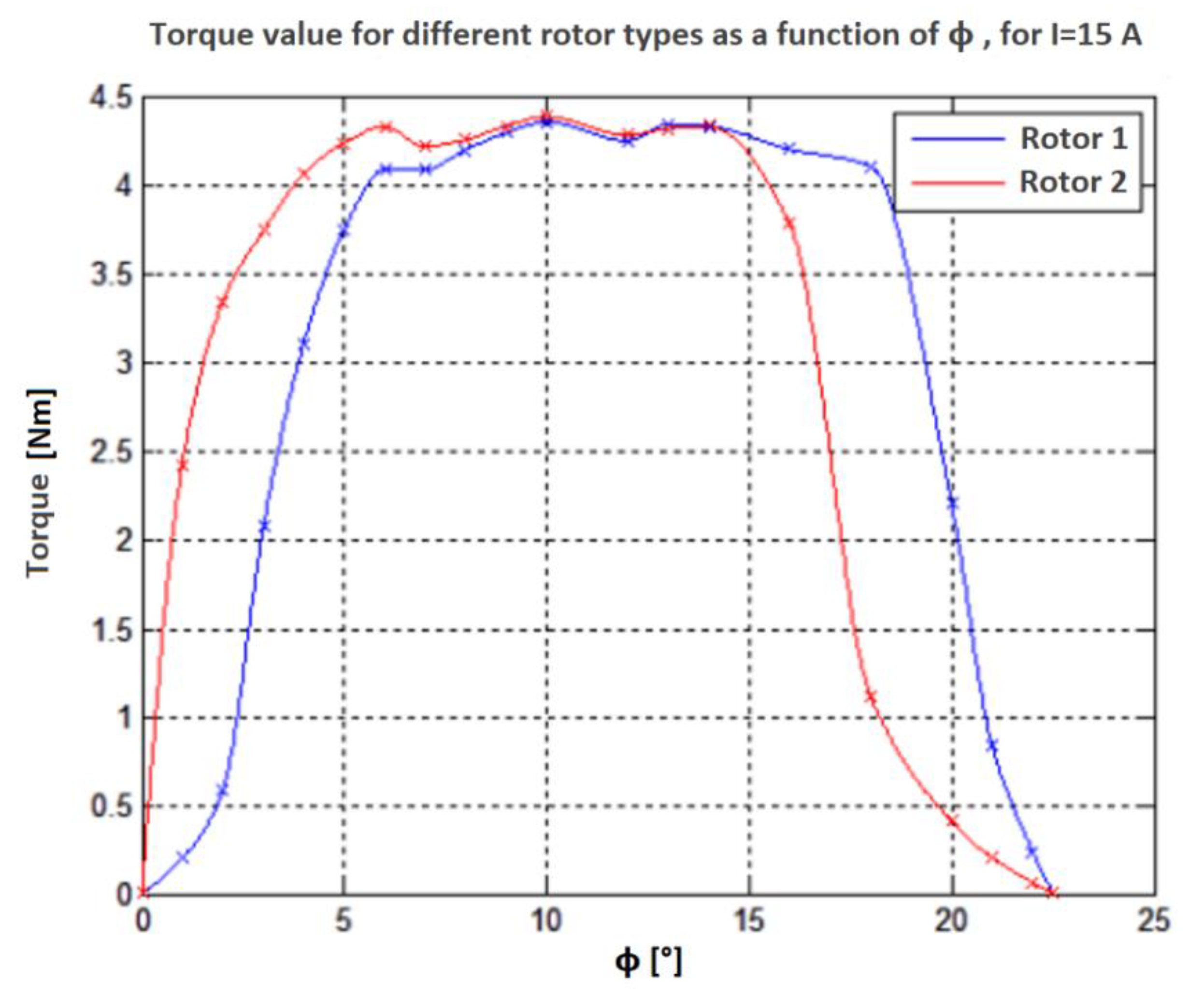
Impact of Changes in Rotor Parameters on the Torque Value
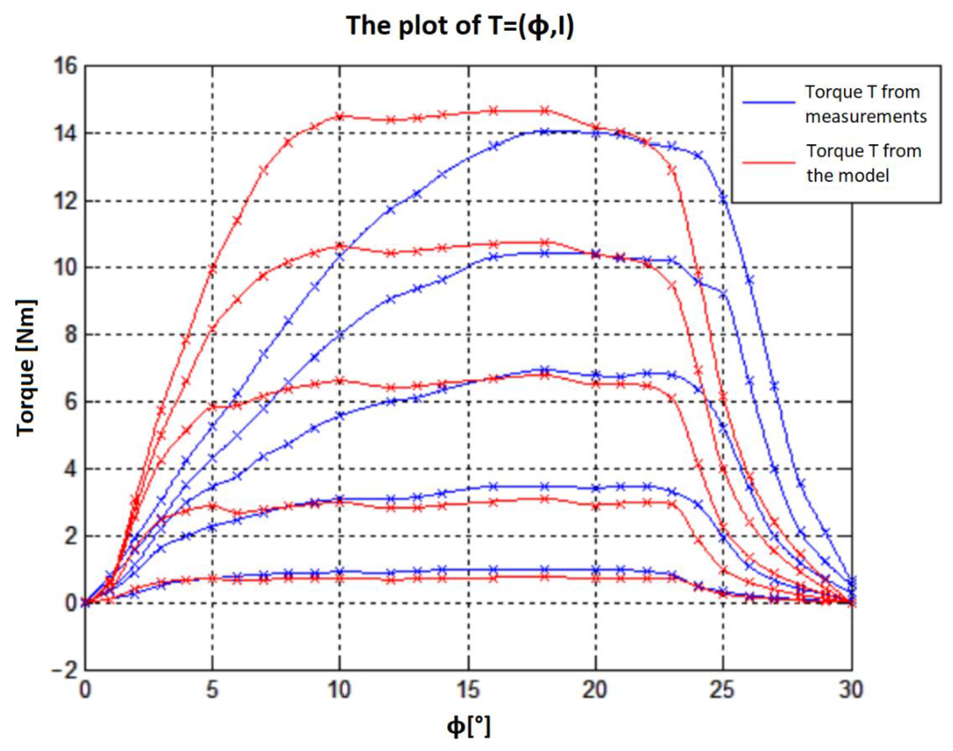
5. Results’ Validation
6. Summary and Conclusions
Author Contributions
Funding
Institutional Review Board Statement
Informed Consent Statement
Data Availability Statement
Acknowledgments
Conflicts of Interest
References
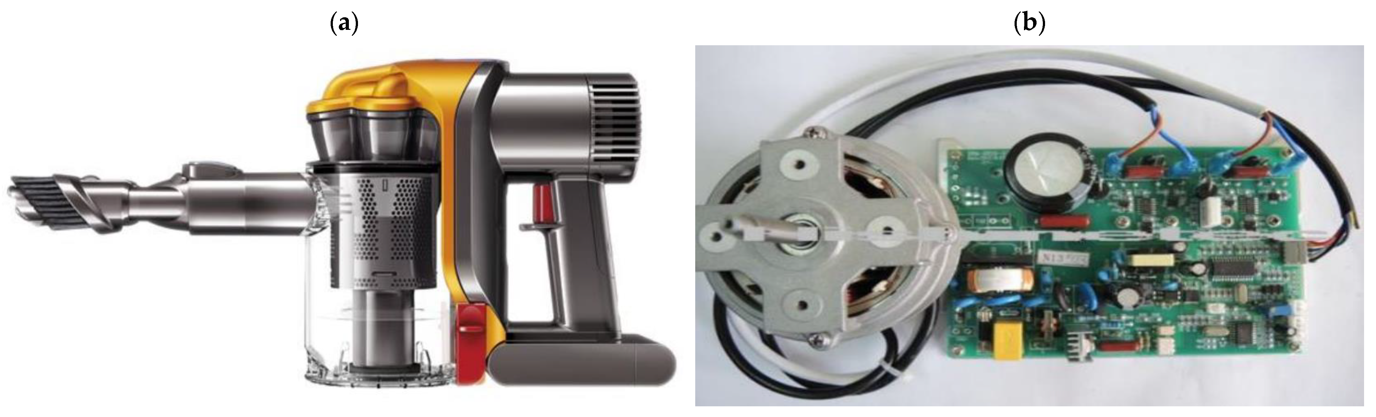
- Data Sheet. Available online: http://www.cadget.com/dyson-dc31-vacuum-cleaner-104000-rpm-of-raw-suction (accessed on 1 September 2021).
- Data Sheet. Available online: https://hishinetech.en.ecplaza.net/products/300w-11000rpm-hand-dryer-bldc-motor_3916921 (accessed on 1 September 2021).
- Tong, J.; Zou, Y. Design of a fuse-time testing system on STM32. In Proceedings of the 2013 International Conference on Computer Sciences and Applications, Wuhan, China, 17–19 October 2013; pp. 406–409. [Google Scholar]
- Makwana, J.A.; Pramod, A.; Srivastava, S.P. Automation and Signal. In Proceedings of the 2011 International Conference on Energy, Bhubaneswar, India, 28–30 December 2011; pp. 1–4. [Google Scholar]
- Hongbo, M.; Hongmei, L.; Liwen, L.; Mingna, M.; Zhiwei, C. SRM Design Based on the Sequence Sub-space Multi-Objective Optimization. In Proceedings of the 2018 21st International Conference on Electrical Machines and Systems, Jeju, Korea, 7–10 October 2018; pp. 1–8. [Google Scholar]
- Hadke, V.V.; Thakre, M.P. Integrated Multilevel Converter Topology for Speed Control of SRM Drive in Plug in-Hybrid Electric Vehicle. In Proceedings of the 2019 3rd International Conference on Trends in Electronics and Infor-matics (ICOEI), Tirunelveli, India, 23–25 April 2019; pp. 1–8. [Google Scholar]
- Nayak, A.R.; Babu, E.; Kumaravel, S. Performance Analysis of Grid Powered Asymmetrical Bridge Converter Driven SRM. In Proceedings of the 2018 15th IEEE India Council International Conference, Coimbatore, India, 16–18 December 2018. [Google Scholar]
- Lotiya, J. Thermal analysis and optimization of temperature rise in busbar joints configuration by FEM. In Proceedings of the 2014 6th IEEE Power India International Conference (PIICON), Delhi, India, 5–7 December 2014; pp. 1–5. [Google Scholar]
- Yaman, G. A thermal analysis for a switchgear system. J. BAUN Inst. Sci. Technol. 2019, 21, 72–80. [Google Scholar]
- Kolimas, Ł.; Łapczyński, S.; Szulborski, M.; Świetlik, M. Low voltage modular circuit breakers: FEM employment for modeling of arc chambers. Bull. Pol. Acad. Sci. Tech. Sci. 2020, 68, 61–70. [Google Scholar]
- Guo, B.; Song, Z.; Fu, P.; Jiang, L.; Wang, M.; Dong, L. Prediction of Temperature Rise in Water-Cooling DC Busbar through Coupled Force and Natural Convection Thermal-Fluid Analysis. IEEE Trans. Plasma Sci. 2016, 44, 3346–3352. [Google Scholar] [CrossRef]
- Thompson, M.K.; Thompson, J.M. ANSYS Mechanical APDL for Finite Element Analysis; Butterworth-Heinemann: Oxford, UK, 2017; ISBN 978-0-12-812981-4. [Google Scholar]
- Kolimas, Ł.; Łapczyński, S.; Szulborski, M. Tulip contacts: Experimental studies of electrical contacts in dynamic layout with the use of FEM software. Int. J. Electr. Eng. Educ. 2019, I, 1–4. [Google Scholar] [CrossRef]
- Cai, J.; Deng, Y. Initial Rotor Position Estimation and Sensorless Control of SRM Based on Coordinate Transformation. IEEE Trans. Instrum. Meas. 2015, 64, 1004–1018. [Google Scholar]
- Masi, A.; Danisi, A.; Losito, R.; Perriard, R. Characterization of magnetic immunity of an ironless inductive position sensor. IEEE Sens. J. 2013, 13, 941–948. [Google Scholar] [CrossRef]
- Yongdae, K.; Choi, H.Y.; Lee, Y.H. Design and preliminary evaluation of high-temperature position sensors for aerospace applications. IEEE Sens. J. 2014, 14, 4018–4025. [Google Scholar]
- Khoshnoud, F.; Silva, C.W. Recent advances in MEMS sensor technology mechanical applications. IEEE Instrum. Meas. Mag. 2012, 15, 14–24. [Google Scholar] [CrossRef]
- Singh, C.B.; Fielke, J.M. Recent developments in strored grain sensors, monitoring and management technology. IEEE Instrum. Meas. Mag. 2017, 20, 32–55. [Google Scholar] [CrossRef]
- Devaney, M.J.; Eren, L. Detecting motor bearing faults. IEEE Instrum. Meas. Mag. 2004, 7, 30–50. [Google Scholar] [CrossRef]
- Fang, P.; Ding, F.; Li, Q. Novel High-Response Electromagnetic Actuator for Electronic Engraving System. IEEE Trans. Magn. 2006, 42, 460–464. [Google Scholar] [CrossRef]
- Nakanishi, Y.; Honda, T.; Kasamura, K.; Nakashima, Y.; Nakano, K.; Kondo, K.; Higaki, H. Bio-inspired shaft seal in coolant pump for electric vehicles. In Proceedings of the IEEE International Conference on Renewable Energy Research and Applications (ICRERA), Birmingham, UK, 20–23 November 2016. [Google Scholar]
- Clark, R.E.; Jewell, G.W.; Forrest, S.J.; Rens, J.; Maerky, J. Design Features for Enhancing the Performance of Electromagnetic Valve Actuation Systems. IEEE Trans. Magn. 2005, 41, 692–696. [Google Scholar] [CrossRef]
- Li, Q.; Ding, F.; Wang, C. Novel bidirectional linear actuator for electrohydraulic valves. IEEE Trans. Magn. 2005, 41, 2199–2201. [Google Scholar]
- An, Y.; Liu, G.; Wang, P.; Wen, H.; Meng, Z. Magnetic force analysis and experiment of novel permanent magnet axial thrust balance structure in canned motor pump. In Proceedings of the IEEE 2nd International Conference on Advanced Computer Control, Shengyang, China, 27–29 March 2010; Volume 1. [Google Scholar]
- Kim, J.; Chang, J. A New Electromagnetic Linear Actuator for Quick Latching. IEEE Trans. Magn. 2007, 43, 1849–1852. [Google Scholar] [CrossRef]
- Huber, C.; Tozzi, P.; Hurni, M.; Segesser, Ł.K. No drive line, no seal, no bearing and no wear: Magnetics for impeller suspension and flow assessment in a new VAD. Interact. Cardiovas. Thorac. Surg. 2004, 3, 336–340. [Google Scholar] [CrossRef] [PubMed]
- Zhao, J.; Seethaler, R.J. A fully flexible valve actuation system for internal combustion engines. IEEE/ASME Trans. Mechatron. 2011, 16, 36–370. [Google Scholar] [CrossRef]
- Ozdalyan, B.; Dogan, O. Effect of a semi electro-mechanical engine valve on performance and emissions in a single cylinder spark ignited engine. J. Zhejiang Univ. Sci. A 2010, 11, 106–114. [Google Scholar] [CrossRef]
- Taji, B.; Chan, A.D.C.; Shirmohammadi, S. Effect of Pressure on Skin-Electrode Impedance in Wearable Biomedical Measurement Devices. IEEE Trans. Instrum. Meas. 2018, 67, 1900–1912. [Google Scholar] [CrossRef]
- Bogusz, P.; Korkosz, M. Switched Reluctance Motor—Theoretical Basis; Electric Drives Control Laboratory: Warsaw, Poland, 2007. [Google Scholar]


| Single Motor Cycle for One of the Phase Bands | |||
|---|---|---|---|
| Turn-On Status of Thyristors T1 and T2 | Status of Work | Voltage at Winding Terminals | |
| Stage I | T1 = on, T2 = on | Switching on the current | Vdc |
| Stage II | T1 = on, T2 = off or T1 = off, T2 = on | Freewheeling | 0 |
| Stage III | T1 = off, T2 = off | Current switch off and current fade | −Vdc |
| Stage IV | T1 = off, T2 = off | Inertia | 0 |
| Parameters | Symbol | Value |
|---|---|---|
| Stator poles’ number | Ns | 6 |
| Stator inside diameter | dsi | 77 |
| Stator outer diameter | dse | 140 |
| Stator pole width | bps | 19 |
| Stator pole height | hps | 16.8 |
| Number of rotor poles | Nr | 4 |
| Rotor internal diameter | dri | 24 |
| Rotor outer diameter | dre | 76 |
| Rotor pole width | bpr | 20 |
| Rotor pole height | hpr | 14.8 |
| Motor length | L | 80 |
| Current | I | 15 |
| Number of coil turns | z | 80 |
| Number of pole pairs on phase | 1 | 1 |
| Rotor Angle | Torque [Nm] | Rotor Angle | Torque [Nm] | Rotor Angle | Torque [Nm] |
|---|---|---|---|---|---|
| 0 | −0.0001 | 16 | 3.6991 | 32 | 1.0923 |
| 2 | 2.4945 | 18 | 3.7235 | 34 | 0.6085 |
| 4 | 3.2499 | 20 | 3.7523 | 36 | 0.3833 |
| 6 | 3.4887 | 22 | 3.7686 | 38 | 0.2503 |
| 8 | 3.5886 | 24 | 3.7720 | 40 | 0.1589 |
| 10 | 3.6403 | 26 | 3.7782 | 42 | 0.0886 |
| 12 | 3.6615 | 28 | 3.7502 | 44 | 0.0284 |
| 14 | 3.7041 | 30 | 2.6322 | 45 | 0.0000 |
| Parameters | Symbol | Value |
|---|---|---|
| Stator poles’ number | Ns | 8 |
| Stator inside diameter | dsi | 74 |
| Stator outer diameter | dse | 130.5 |
| Stator pole width | bps | 14 |
| Stator pole height | hps | 15 |
| Rotor poles’ number | Nr | 6 |
| Rotor internal diameter | dri | 32 |
| Rotor diameter | dre | 73.2 |
| Rotor pole width | bpr | 16 |
| Rotor pole height | hpr | 12.5 |
| Motor length | L | 120 |
| Current | I | 5–25 |
| Number of coil turns | z | 80 |
| Number of pole pairs on phase | 1 | 1 |
| Rotor Angle φ [°] | Torque [Nm] 5 A | Torque [Nm] 10 A | Torque [Nm] 15 A | Torque [Nm] 20 A | Torque [Nm] 25 A |
|---|---|---|---|---|---|
| 0 | 0.0001 | 0.0013 | 0.0009 | 0.0012 | 0.0012 |
| 1 | 0.0990 | 0.3755 | 0.5354 | 0.5923 | 0.6424 |
| 2 | 0.3933 | 1.6147 | 2.5442 | 2.8108 | 3.0684 |
| 3 | 0.5968 | 2.4342 | 4.2168 | 4.9915 | 5.7309 |
| 4 | 0.6671 | 2.7190 | 5.1132 | 6.5794 | 7.8367 |
| 5 | 0.7042 | 2.8709 | 5.7936 | 8.1439 | 9.9157 |
| 6 | 0.6469 | 2.6631 | 5.8562 | 9.0109 | 11.4146 |
| 7 | 0.6768 | 2.7569 | 6.1502 | 9.7359 | 12.8543 |
| 8 | 0.6971 | 2.8444 | 6.3500 | 10.1357 | 13.7330 |
| 9 | 0.7165 | 2.9218 | 6.4907 | 10.4118 | 14.1882 |
| 10 | 0.7299 | 2.9769 | 6.5915 | 10.5884 | 14.4956 |
| 12 | 0.6789 | 2.7940 | 6.4023 | 10.4099 | 14.3837 |
| 13 | 0.6923 | 2.8231 | 6.5193 | 10.5484 | 14.4454 |
| 16 | 0.7350 | 2.9998 | 6.6544 | 10.6744 | 14.6459 |
| 18 | 0.7562 | 3.0878 | 6.7620 | 10.7278 | 14.6543 |
| 20 | 0.7072 | 2.8913 | 6.4819 | 10.2729 | 14.1786 |
| 21 | 0.7211 | 2.9459 | 6.4969 | 10.3487 | 14.0274 |
| 22 | 0.7308 | 2.9836 | 6.4524 | 10.0601 | 13.7089 |
| 23 | 0.7262 | 2.9305 | 6.0658 | 9.4233 | 12.8573 |
| 24 | 0.4676 | 1.8704 | 4.1416 | 6.9285 | 9.8715 |
| 25 | 0.2499 | 0.9996 | 2.2489 | 3.9732 | 6.1285 |
| 26 | 0.1512 | 0.6048 | 1.3608 | 2.4191 | 3.7752 |
| 27 | 0.0954 | 0.3817 | 0.8588 | 1.5268 | 2.3857 |
| 28 | 0.573 | 0.2290 | 0.5153 | 0.9161 | 1.4314 |
| 29 | 0.0262 | 0.1047 | 0.2355 | 0.4187 | 0.6542 |
| 30 | −0.0001 | −0.0003 | −0.0006 | −0.0011 | −0.0017 |
| Parameters | Symbol | Value |
|---|---|---|
| Stator poles’ number | Ns | 10 |
| Stator inside diameter | dsi | 95.6 |
| Stator outer diameter | dse | 160 |
| Stator pole width | bps | 14 |
| Stator pole height | hps | 13.8 |
| Rotor poles’ number | Nr | 8 |
| Rotor internal diameter | dri | 32 |
| Rotor diameter | dre | 94.8 |
| Rotor pole width | bpr | 16 |
| Rotor pole height | hpr | 13.8 |
| Motor length | L | 60 |
| Current | I | 5–25 |
| Number of coil turns | z | 80 |
| Number of pole pairs on phase | 1 | 1 |
| Rotor Angle φ [°] | Torque [Nm] 5 A | Torque [Nm] 10 A | Torque [Nm] 15 A | Torque [Nm] 20 A | Torque [Nm] 25 A |
|---|---|---|---|---|---|
| 0 | 0.0015 | 0.0069 | 0.0078 | 0.0080 | 0.0081 |
| 1 | 0.1298 | 0.4672 | 0.6711 | 0.7359 | 0.7974 |
| 2 | 0.4167 | 1.5985 | 2.6528 | 3.0662 | 3.4598 |
| 3 | 0.4363 | 1.7157 | 3.2642 | 4.2312 | 5.0789 |
| 4 | 0.4752 | 1.8616 | 3.8405 | 5.5679 | 6.8719 |
| 5 | 0.4997 | 1.9506 | 4.1534 | 6.4193 | 8.3172 |
| 6 | 0.5192 | 2.0225 | 4.3314 | 6.7865 | 9.1356 |
| 8 | 0.5007 | 1.9699 | 4.3189 | 6.8958 | 9.4446 |
| 10 | 0.5201 | 2.0296 | 4.4108 | 7.0224 | 9.6064 |
| 12 | 0.4957 | 1.9575 | 4.3296 | 6.9218 | 9.4799 |
| 14 | 0.5160 | 2.0176 | 4.3922 | 6.9520 | 9.4866 |
| 15 | 0.5252 | 2.0479 | 4.4166 | 6.9363 | 9.4344 |
| 16 | 0.4875 | 1.9302 | 4.2433 | 6.6827 | 9.1008 |
| 17 | 0.4949 | 1.9476 | 4.1633 | 6.4894 | 8.8133 |
| 18 | 0.4643 | 1.8170 | 3.7045 | 5.7332 | 7.8563 |
| 19 | 0.2090 | 0.8360 | 1.8791 | 3.1904 | 4.7602 |
| 20 | 0.1029 | 0.4117 | 0.9263 | 1.6465 | 2.5349 |
| 22 | 0.0143 | 0.0571 | 0.1285 | 0.2284 | 0.3569 |
| 22.5 | 0.0001 | 0.0003 | 0.0006 | 0.0011 | 0.0017 |
| Rotor Angle φ [°] | Torque [Nm] 5 A | Torque [Nm] 10 A | Torque [Nm] 15 A | Torque [Nm] 20 A | Torque [Nm] 25 A |
|---|---|---|---|---|---|
| 0 | 0 | 0 | 0 | 0 | 0 |
| 1 | 0.096695 | 0.318525 | 0.395312 | 0.665490 | 0.790625 |
| 2 | 0.261646 | 0.893008 | 1.126214 | 1.555654 | 1.931058 |
| 3 | 0.506227 | 1.623909 | 2.195548 | 2.479945 | 3.045896 |
| 4 | 0.648426 | 1.959498 | 2.957733 | 3.492400 | 4.220457 |
| 5 | 0.710993 | 2.260959 | 3.426988 | 4.271649 | 5.213004 |
| 6 | 0.776405 | 2.457193 | 3.756889 | 4.959890 | 6.211239 |
| 7 | 0.830440 | 2.664803 | 4.348436 | 5.750515 | 7.368736 |
| 8 | 0.864568 | 2.861038 | 4.726684 | 6.563891 | 8.395410 |
| 9 | 0.890164 | 2.980484 | 5.204472 | 7.306168 | 9.387957 |
| 10 | 0.895852 | 3.065804 | 5.542905 | 7.965970 | 10.28096 |
| 12 | 0.893008 | 3.062960 | 5.980877 | 9.035305 | 11.73424 |
| 13 | 0.927135 | 3.131215 | 6.088948 | 9.331078 | 12.20349 |
| 14 | 0.958419 | 3.247818 | 6.316466 | 9.595567 | 12.75522 |
| 16 | 0.978327 | 3.446896 | 6.674806 | 10.27043 | 13.58851 |
| 18 | 0.955575 | 3.461116 | 6.916544 | 10.41463 | 14.03501 |
| 20 | 0.949887 | 3.407081 | 6.748750 | 10.36913 | 13.97813 |
| 21 | 0.961263 | 3.449740 | 6.720310 | 10.22693 | 13.90134 |
| 22 | 0.918604 | 3.455428 | 6.822693 | 10.20702 | 13.69373 |
| 23 | 0.813376 | 3.299010 | 6.774345 | 10.16721 | 13.57997 |
| 24 | 0.480632 | 2.903697 | 6.344905 | 9.550064 | 13.32402 |
| 25 | 0.324213 | 1.939590 | 5.198784 | 9.194567 | 12.03854 |
| 26 | 0.204766 | 1.083554 | 3.426988 | 6.603707 | 9.589879 |
| 27 | 0.136511 | 0.665490 | 1.959498 | 3.978719 | 6.433069 |
| 28 | 0.085319 | 0.406688 | 1.180249 | 2.113072 | 3.532215 |
| 29 | 0.042660 | 0.241738 | 0.699618 | 1.214377 | 2.076101 |
| 30 | 0 | 0.059723 | 0.295773 | 0.560263 | 0.648426 |
| Rotor Angle φ [°] | Torque [Nm] 5 A | Torque [Nm] 10 A | Torque [Nm] 15 A | Torque [Nm] 20 A | Torque [Nm] 25 A |
|---|---|---|---|---|---|
| 0 | 0 | 0 | 0 | 0 | 0 |
| 1 | 0.352653 | 0.981171 | 1.470334 | 1.666569 | 1.726292 |
| 2 | 0.423752 | 1.387859 | 2.150044 | 2.681867 | 3.347357 |
| 3 | 0.466412 | 1.572717 | 2.599392 | 3.481024 | 4.183485 |
| 4 | 0.494851 | 1.717760 | 3.011768 | 4.046975 | 5.249975 |
| 5 | 0.514759 | 1.834363 | 3.378641 | 4.903011 | 6.336373 |
| 6 | 0.537511 | 1.936746 | 3.731294 | 5.505933 | 7.155438 |
| 8 | 0.557419 | 2.076101 | 4.123762 | 6.379033 | 8.349907 |
| 10 | 0.568795 | 2.132980 | 4.268805 | 6.751594 | 9.015397 |
| 12 | 0.574483 | 2.175640 | 4.339904 | 6.828381 | 9.180347 |
| 14 | 0.577327 | 2.206924 | 4.419535 | 6.893792 | 9.245759 |
| 15 | 0.580171 | 2.212612 | 4.402471 | 6.859665 | 9.203099 |
| 16 | 0.583015 | 2.218299 | 4.337060 | 6.646367 | 9.026773 |
| 17 | 0.528979 | 2.053349 | 3.882024 | 6.131607 | 8.381191 |
| 18 | 0.261646 | 1.180249 | 2.312151 | 4.086790 | 6.131607 |
| 19 | 0.127979 | 0.597234 | 1.370795 | 2.306463 | 3.586251 |
| 20 | 0.076787 | 0.355497 | 0.782093 | 1.299696 | 2.178484 |
| 22 | 0 | 0.085319 | 0.199078 | 0.312837 | 0.602922 |
| 22.5 | 0 | 0 | 0 | 0 | 0 |
Publisher’s Note: MDPI stays neutral with regard to jurisdictional claims in published maps and institutional affiliations. |
© 2021 by the authors. Licensee MDPI, Basel, Switzerland. This article is an open access article distributed under the terms and conditions of the Creative Commons Attribution (CC BY) license (https://creativecommons.org/licenses/by/4.0/).
Share and Cite
Bieńkowski, K.; Szulborski, M.; Łapczyński, S.; Kolimas, Ł.; Cichecki, H. Parameterized 2D Field Model of a Switched Reluctance Motor. Electricity 2021, 2, 590-613. https://doi.org/10.3390/electricity2040034
Bieńkowski K, Szulborski M, Łapczyński S, Kolimas Ł, Cichecki H. Parameterized 2D Field Model of a Switched Reluctance Motor. Electricity. 2021; 2(4):590-613. https://doi.org/10.3390/electricity2040034
Chicago/Turabian StyleBieńkowski, Krzysztof, Michał Szulborski, Sebastian Łapczyński, Łukasz Kolimas, and Hubert Cichecki. 2021. "Parameterized 2D Field Model of a Switched Reluctance Motor" Electricity 2, no. 4: 590-613. https://doi.org/10.3390/electricity2040034