
Standalone Operation of Inverter-Based Variable Speed Wind Turbines on DC Distribution Network


Abstract
1. Introduction
- Limited adaptability to load variations, particularly in networks supplying unbalanced AC loads.
- Complex centralized control schemes that increase communication overhead and computational burden.
- Lack of a decentralized and scalable voltage regulation strategy for isolated LVDC networks.
- Implementation of a droop control strategy for DC voltage regulation in isolated networks.
- Standalone operation and control of inverter-based variable-speed wind turbines, ensuring stable and efficient integration into DC microgrids.
- Utilization of an isolated DC distribution network for wind turbine integration, accounting for wind power fluctuations.
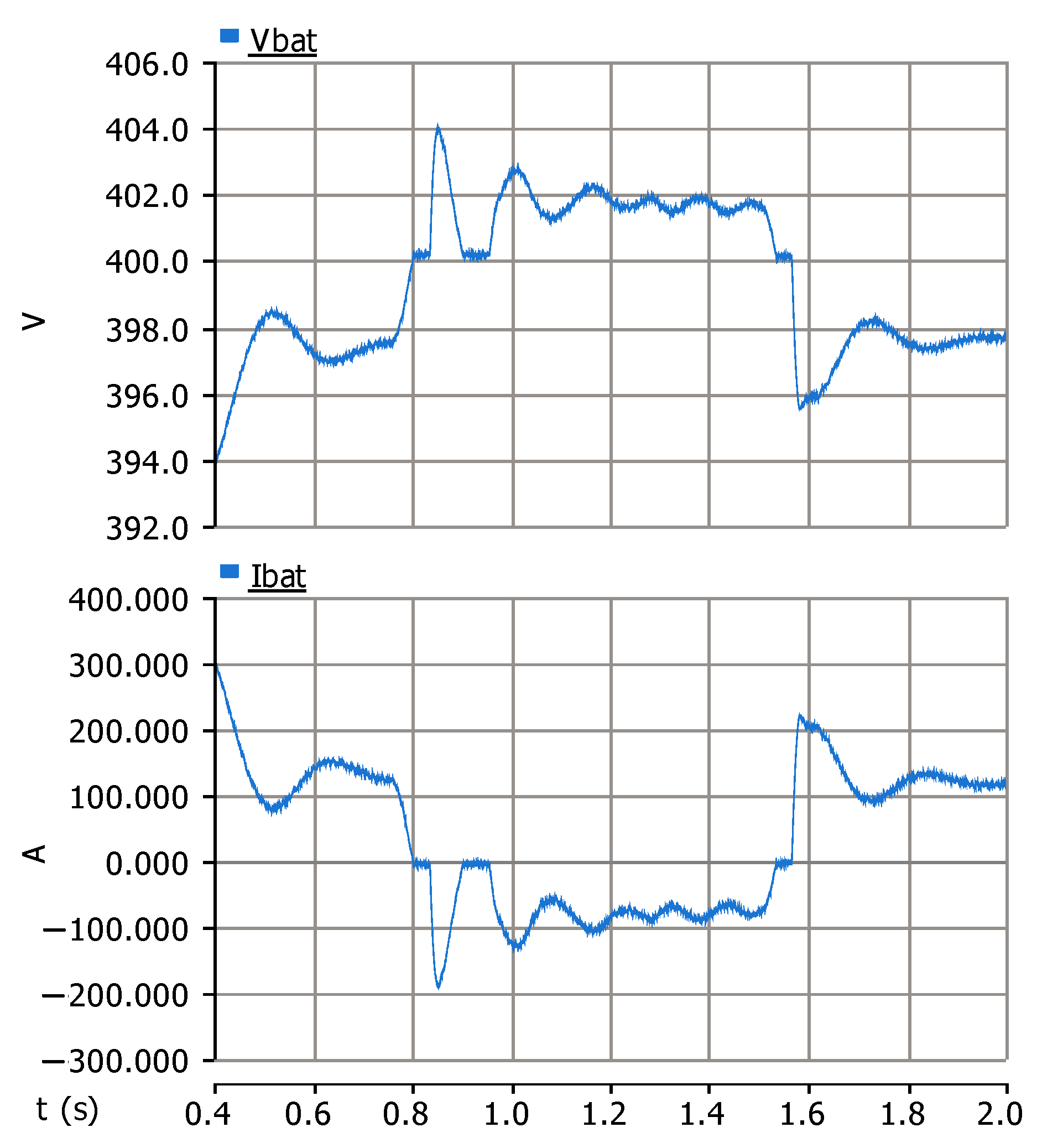
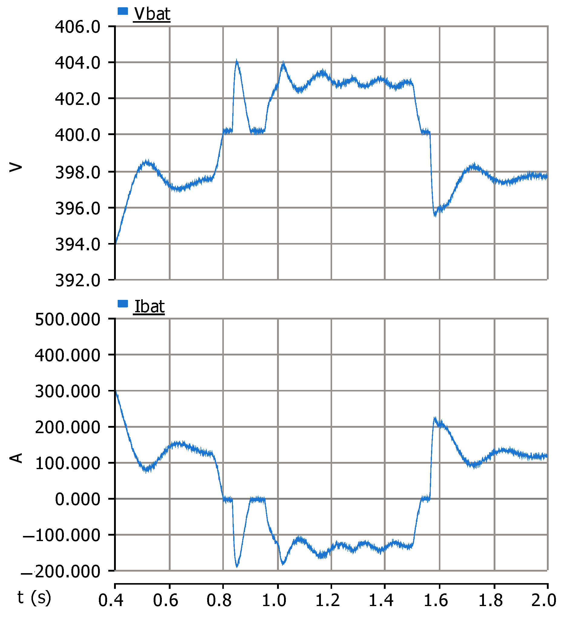
- Efficient energy management and battery storage utilization, where the battery system plays a critical role in DC voltage regulation and dynamic response to load and generation variations.
- Introducing a novel network architecture that serves as a promising and innovative solution for future power grids, enhancing resilience, flexibility, and reliability in renewable energy integration.
- Coordinated control of WTIG and storage converters to ensure continuous power supply under varying wind and load conditions.
- Improvement of power quality through balanced AC voltage regulation despite unbalanced loads.
2. Standalone Distribution System Configuration
Unbalanced Load Characteristics
- Mild Unbalance (5–10%): Characterized by small phase deviations that minimally impact system performance.
- Moderate Unbalance (10–20%): Characterized by noticeable phase asymmetry, which degrades power quality.
- Severe Unbalance (20–30%): Characterized by significant current imbalance, causing voltage fluctuations.
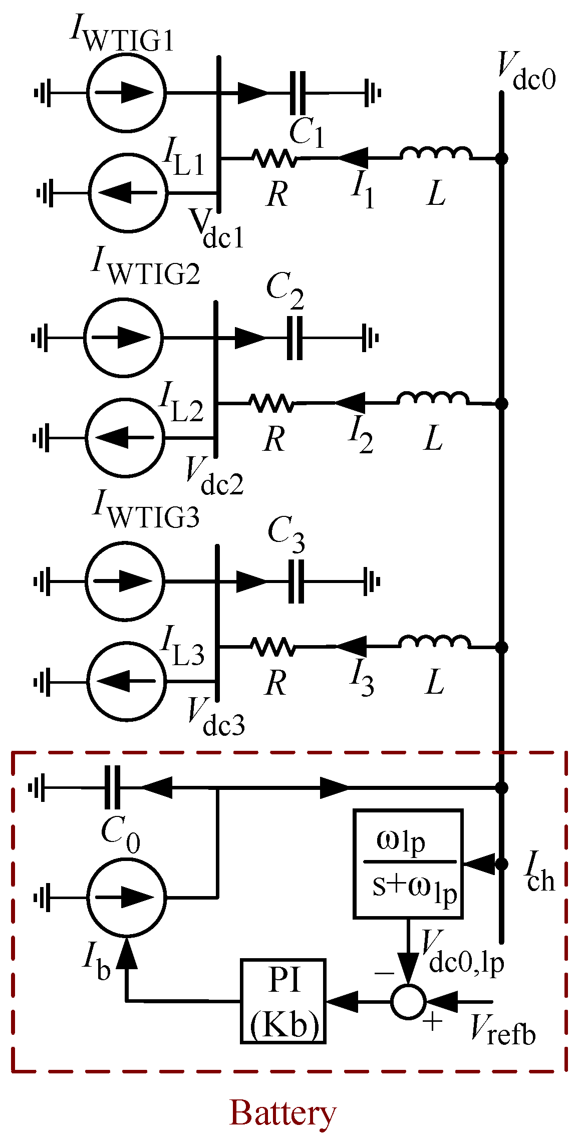
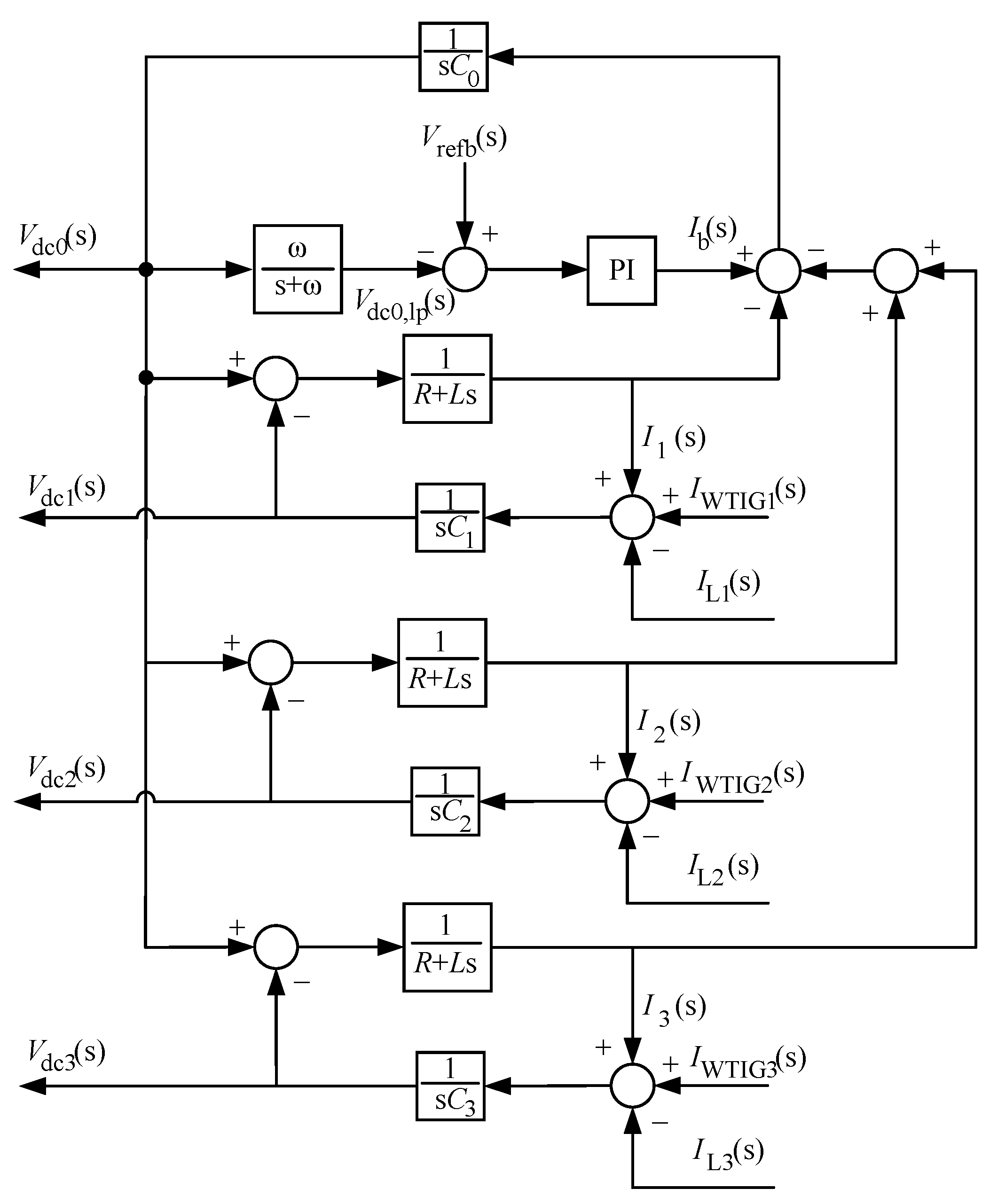
3. Modeling of DC Side Dynamic
- If , the power generated by inverter-based variable-speed wind turbine units increases, or the load consumption decreases. The surplus power in the DC network is transferred to the battery via the storage converter.
- If , the power generated by variable-speed wind turbine units based on inverters decreases, or the load consumption increases. In this scenario, the battery supplies the required power via the storage converter.
- If , the power generated by inverter-based variable-speed wind turbine units matches the load demand. Under this condition, no power is injected into or drawn from the battery via the storage converter.
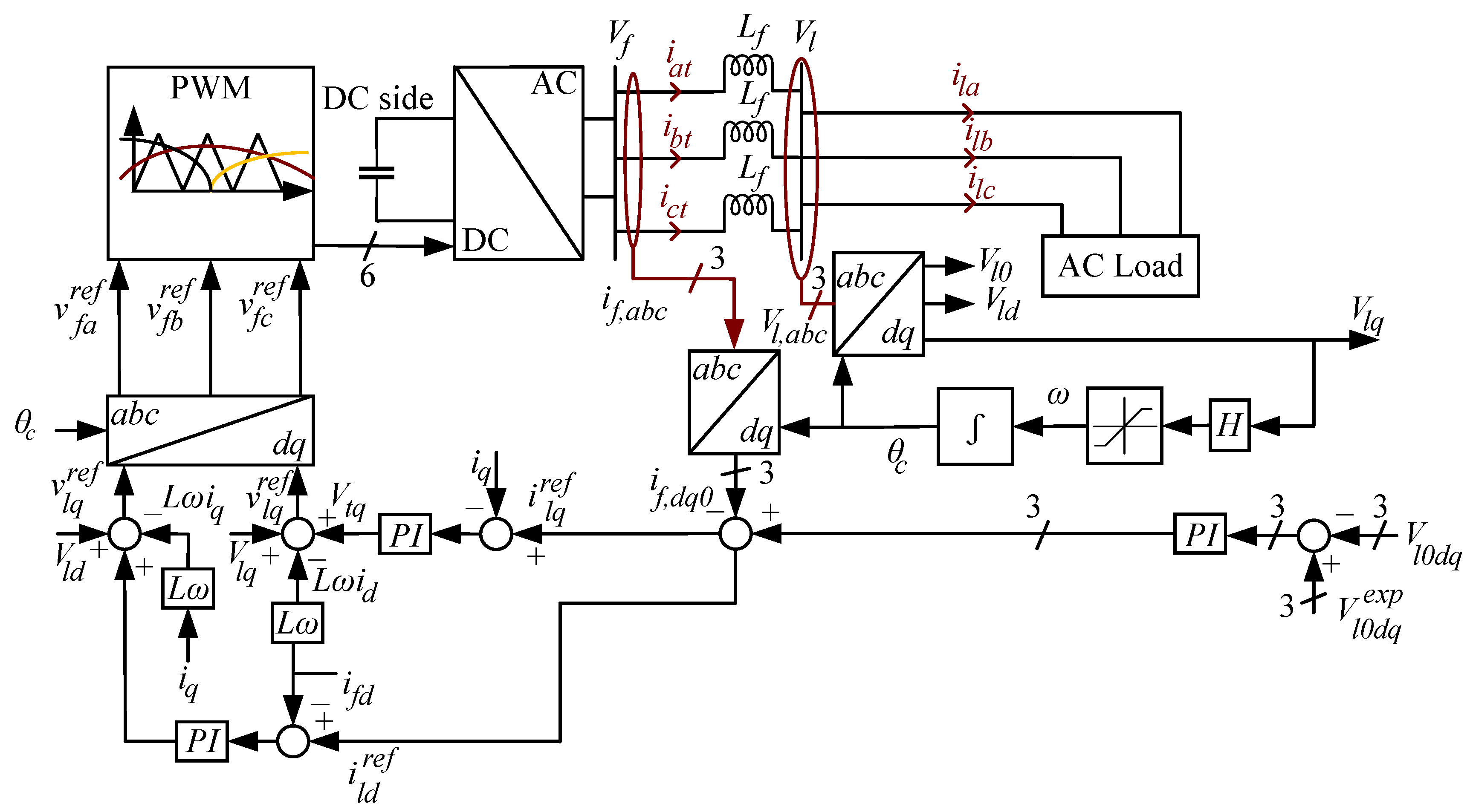
4. The Power Converters and Inverters Control Strategy
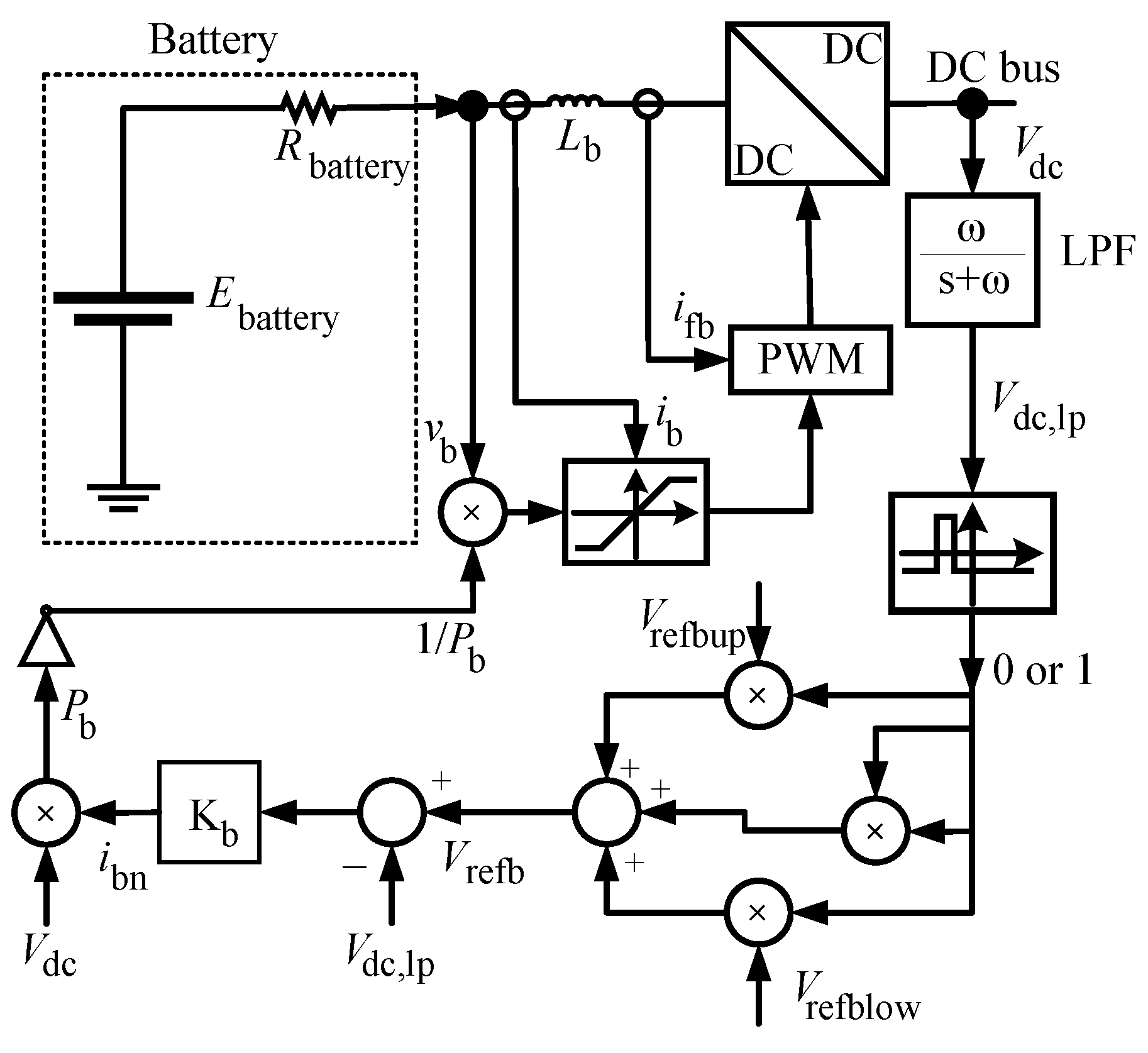
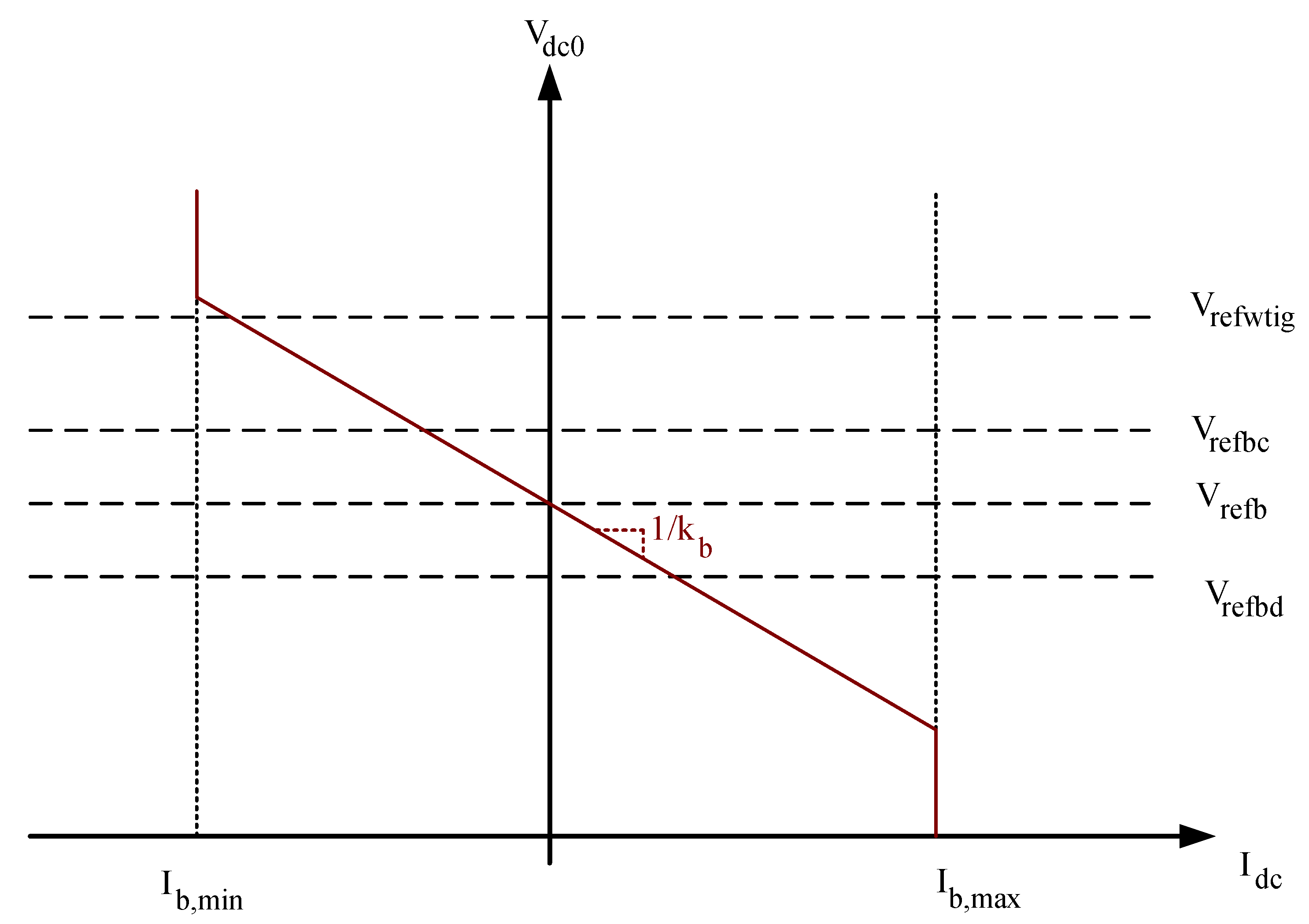
4.1. Energy Storage Units
- (Upper Limit): Restricts the maximum charging current to prevent overcharging.
- (Lower Limit): Defines the discharge current threshold.
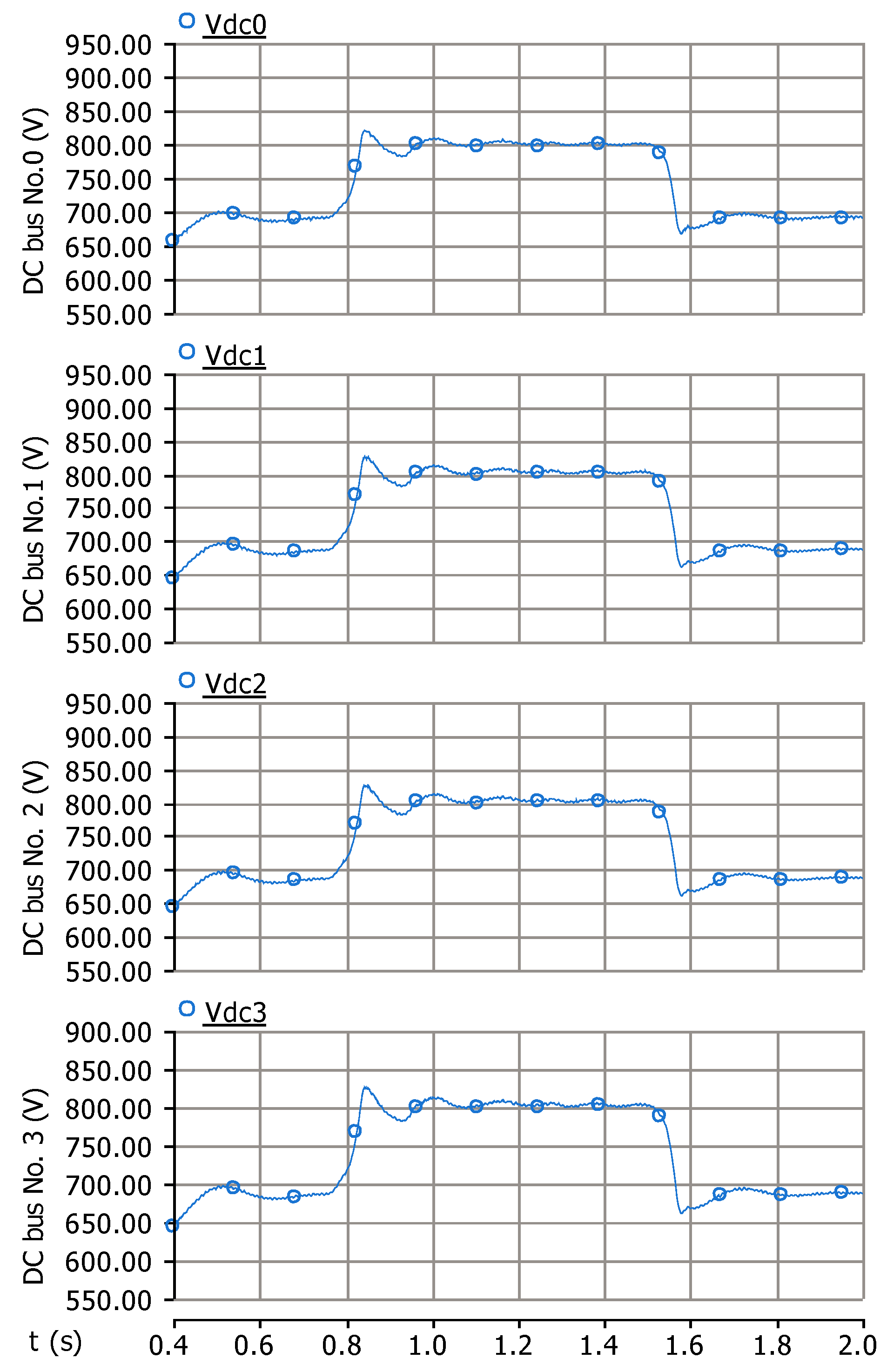
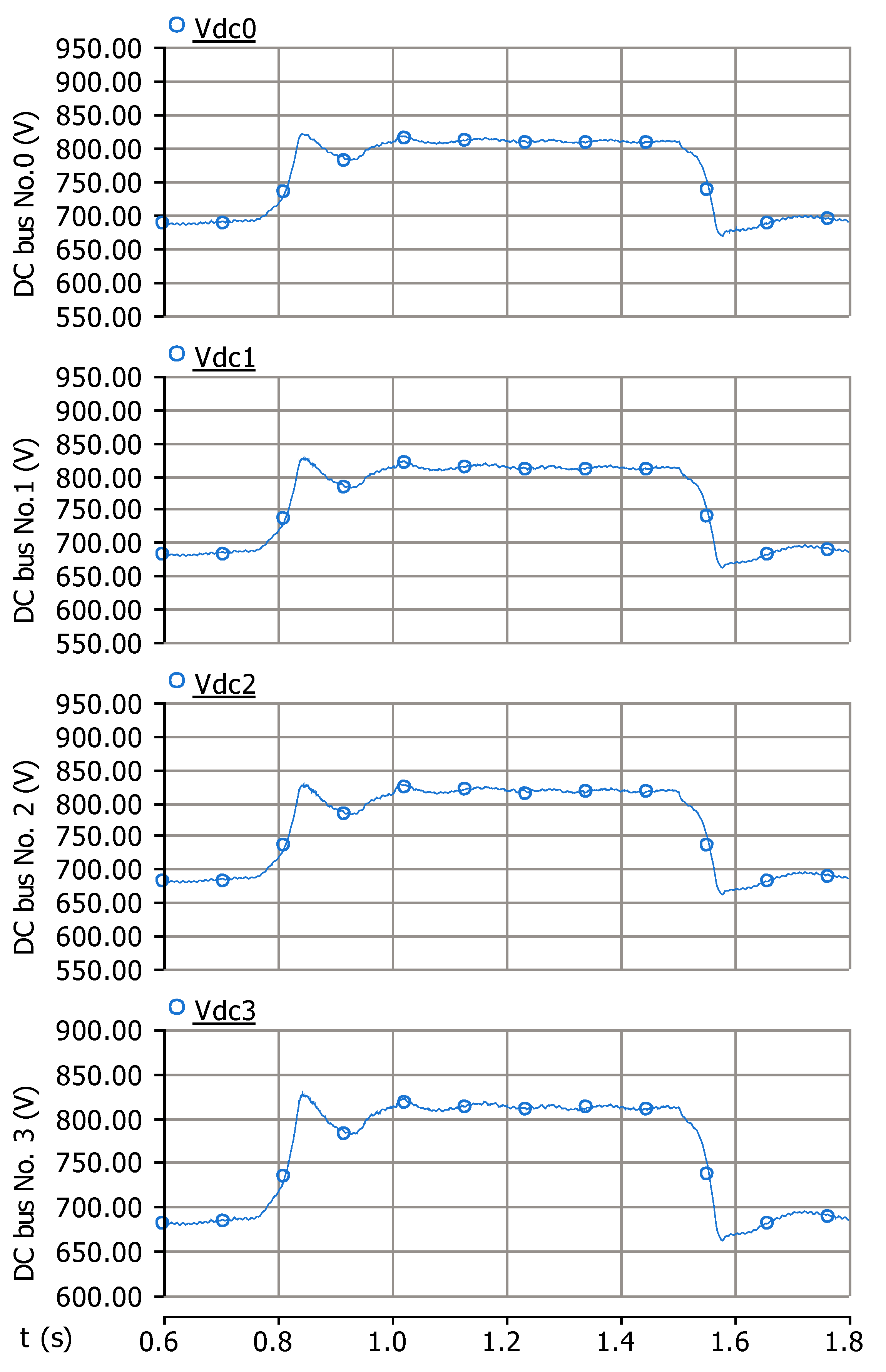
- DC Bus Voltage Regulation: Maintains voltage stability by dynamically regulating power exchange between the battery storage system and the network.
- Wind Turbine Power Control: Maximizes wind energy extraction while maintaining operational limits.
- Inverter-Based Load Management: Balances power delivery to unbalanced AC loads, ensuring a stable and reliable power supply.
- is the DC bus voltage.
- is the storage system’s reference voltage.
- is the output current of the storage converter, and
- m is the droop coefficient, which determines the slope of the voltage-current characteristic.
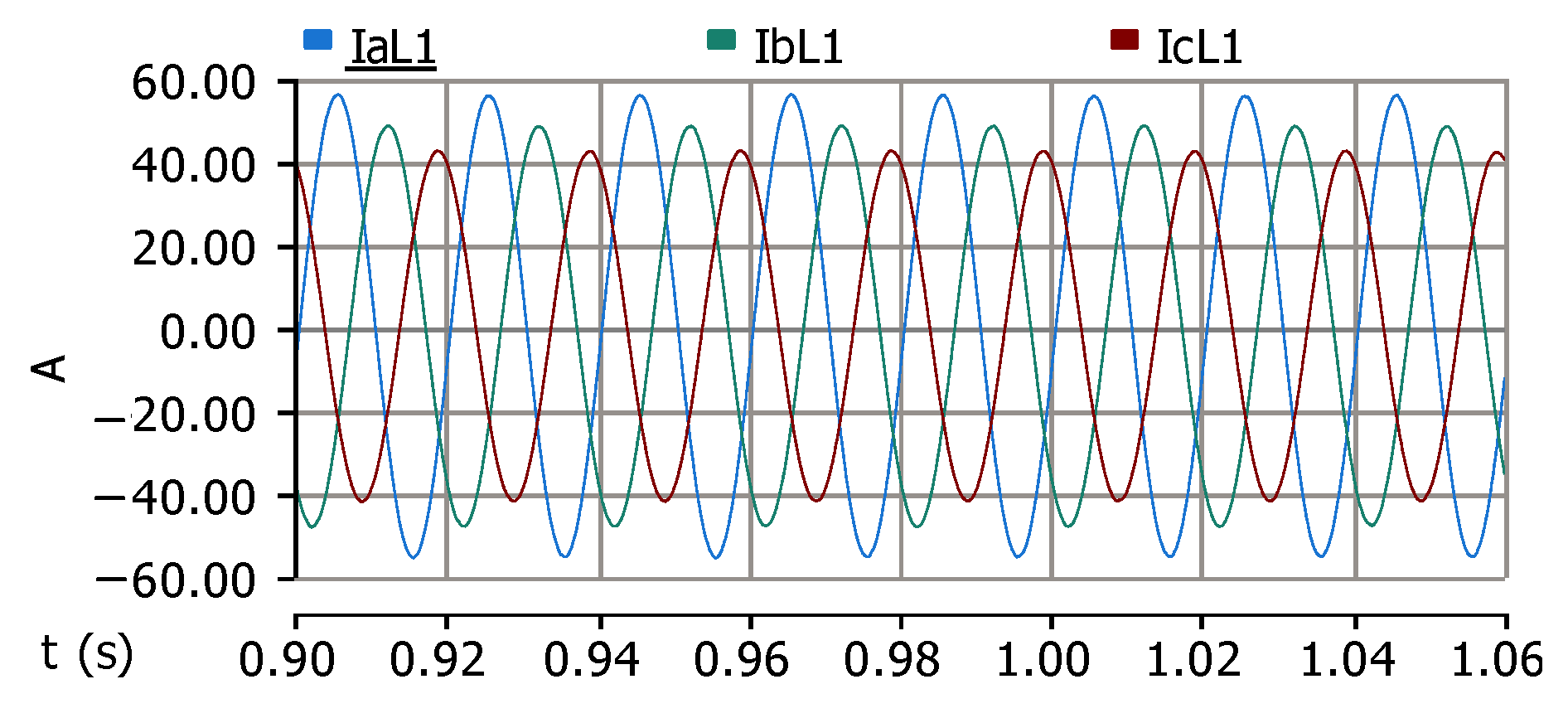
4.2. WTIG Unit
- represents the reference current for phase .
- is the power demand of the load in phase , and
- represents the instantaneous voltage of phase .
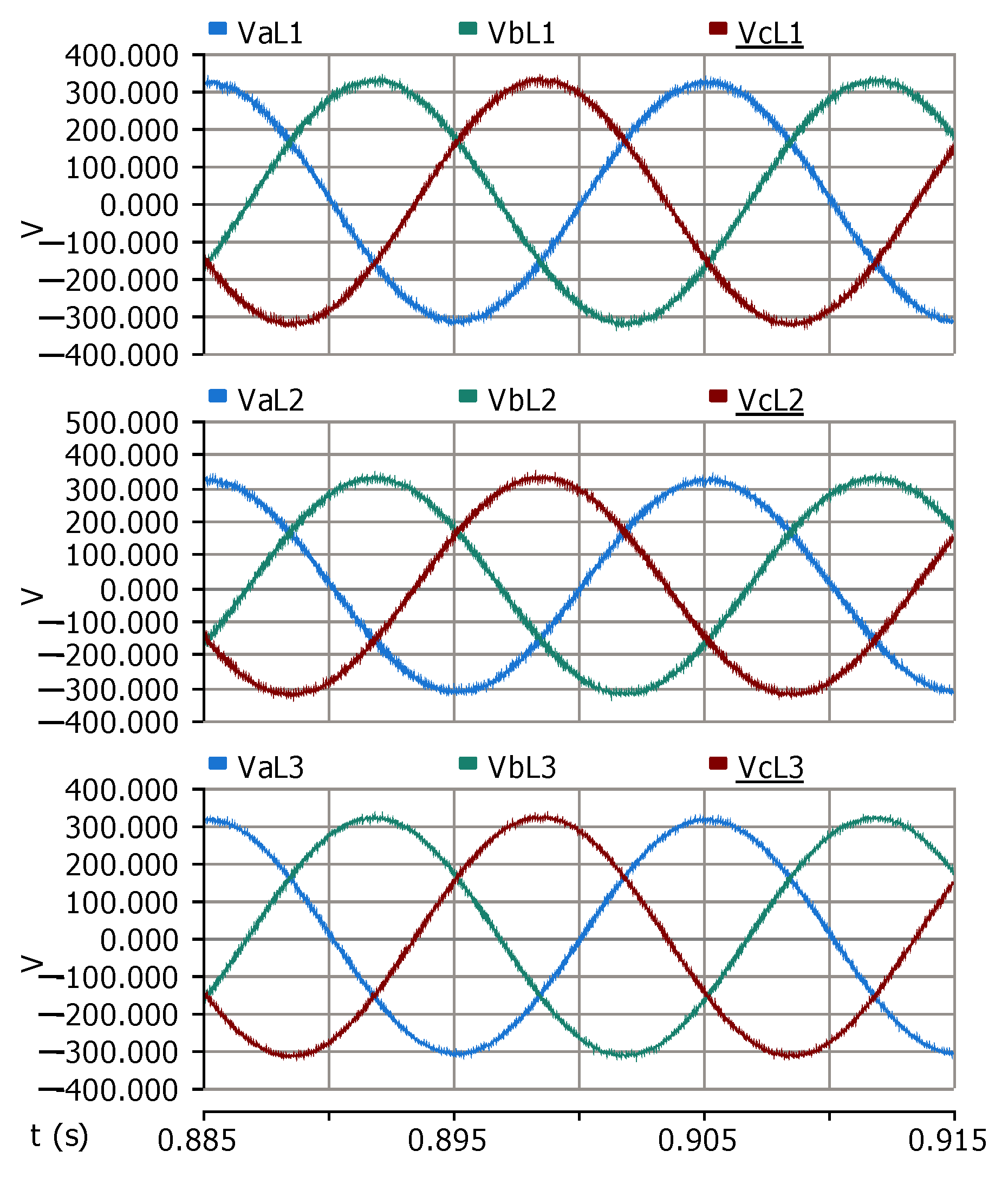
4.3. AC Load Units
- The frequency () is managed by a Phase-Locked Loop (PLL), synchronized with the desired operating frequency.
- The phase voltages at the load (, , and ) are measured, followed by conversion to the synchronously rotating d–q–0 frame.
5. Simulation Results
5.1. Scenario 1 (No Disturbance of Wind Turbine Operation)
5.2. Scenario 2 (Wind Speed Variation)
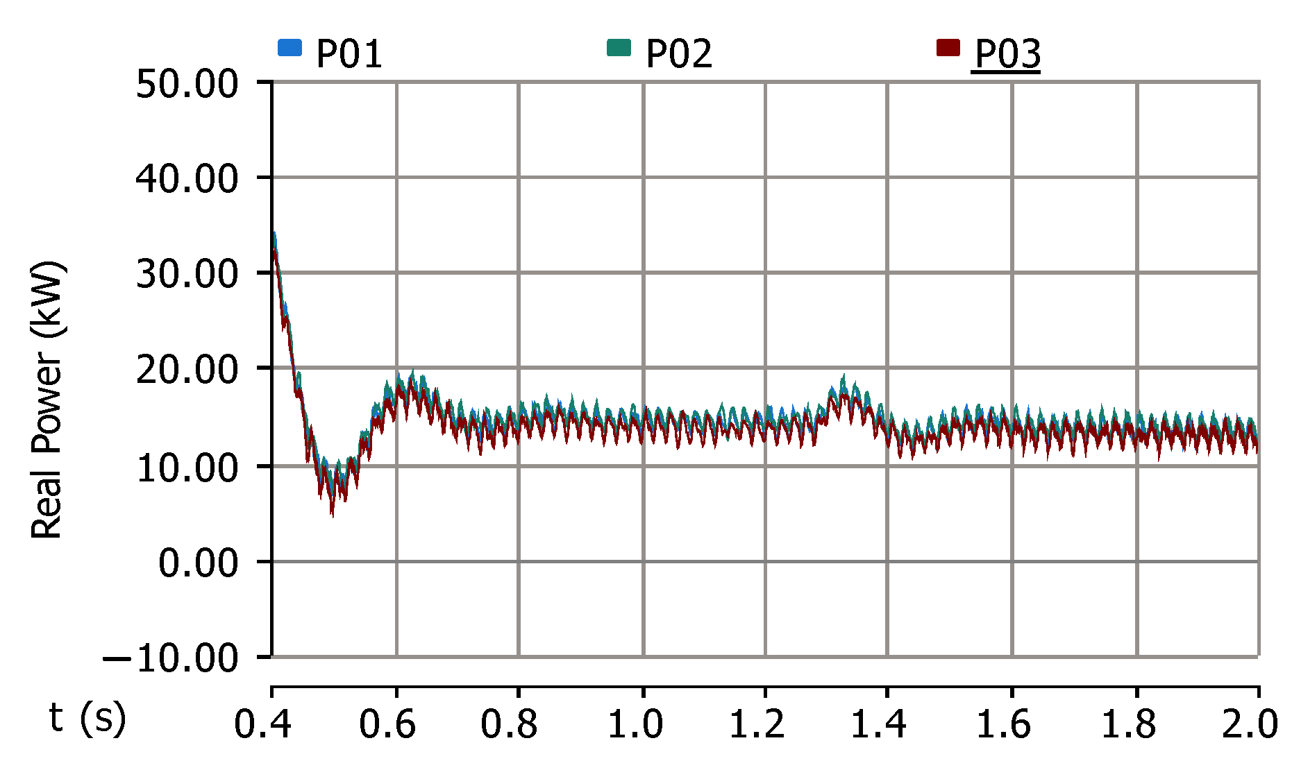
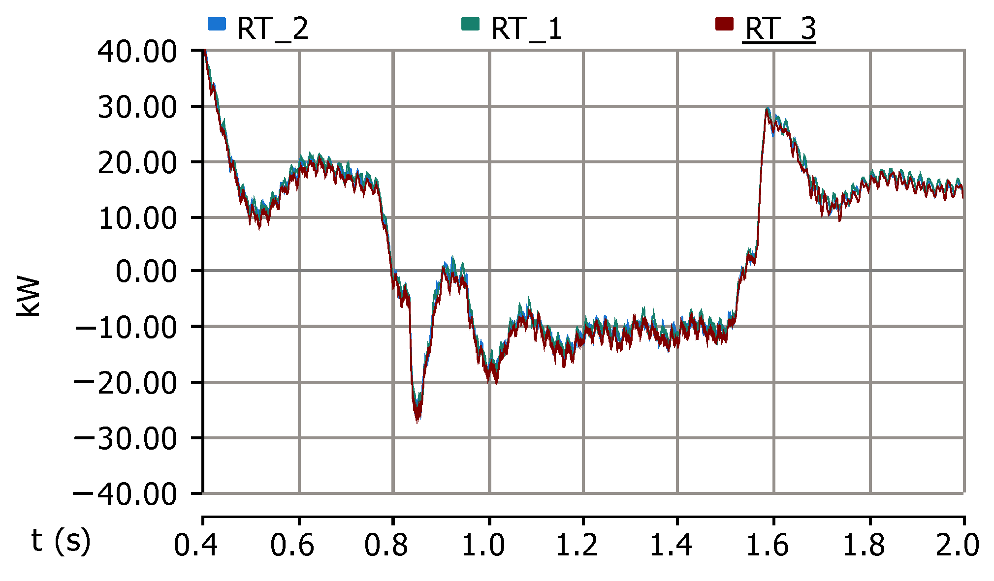
5.3. Scenario 3 (Load Variation)
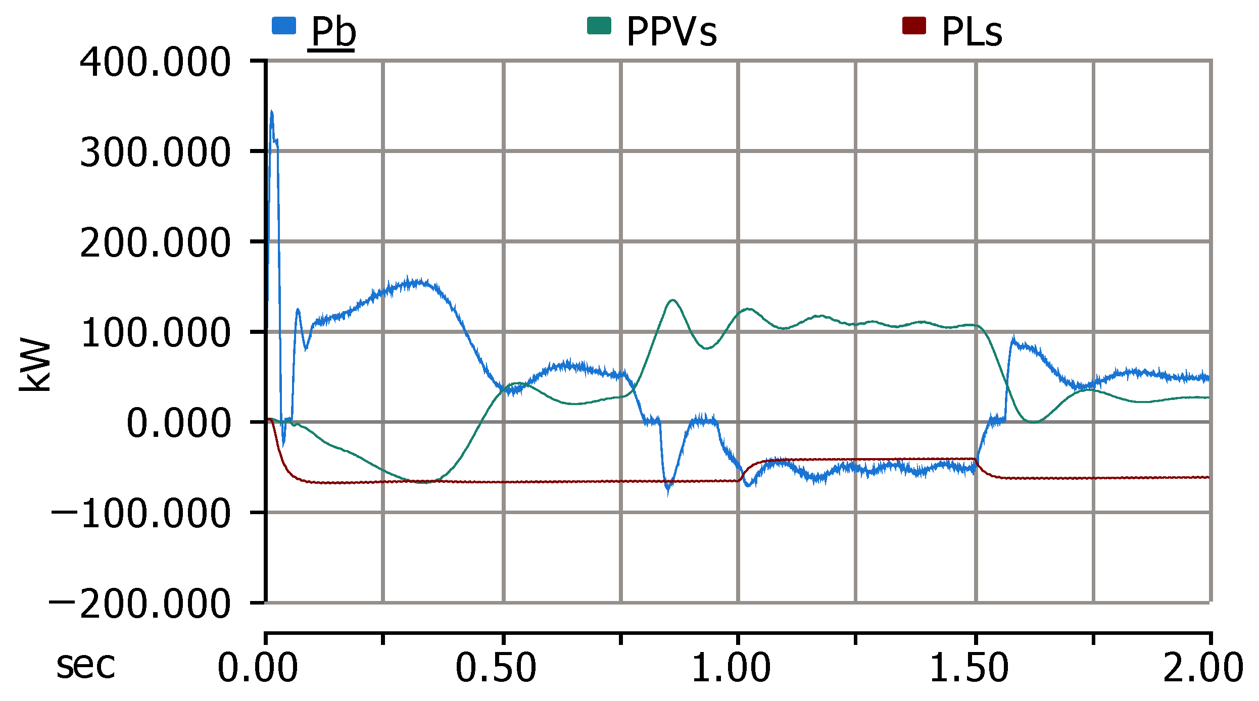
- represents the total power generated by the wind turbine induction generator (WTIG).
- is the actual power delivered to the DC bus and utilized by loads or stored in the battery.
6. Conclusions
Author Contributions
Funding
Data Availability Statement
Conflicts of Interest
References
- Esmaili, G. Application of Advanced Power Electronics in Renewable Energy Sources and Hybrid Generating Systems. Ph.D. Thesis, The Ohio State University, Columbus, OH, USA, 2006. [Google Scholar]
- Li, B.; Sheng, J.; Xu, L.; Shi, T.; Fan, S.; Xiang, X.; Zhang, X.; Li, W. Power Flow Control of Bidirectional Modular Multilevel Resonant Converters in MVDC and LVDC Distribution Networks. IEEE Trans. Power Electron. 2024, 40, 1168–1182. [Google Scholar] [CrossRef]
- Javid, Z.; Kocar, I.; Holderbaum, W.; Karaagac, U. Future Distribution Networks: A Review. Energies 2024, 17, 1822. [Google Scholar] [CrossRef]
- Azbe, V.; Mihalic, R. Distributed generation from renewable sources in an isolated DC network. Renew. Energy 2006, 31, 2370–2384. [Google Scholar] [CrossRef]
- Jovcic, D.; Strachan, N. Offshore wind farm with centralised power conversion and DC interconnection. IET Gener. Transm. Distrib. 2009, 3, 586–595. [Google Scholar] [CrossRef]
- Higuchi, Y.; Yamamura, N.; Ishida, M.; Hori, T. An improvement of performance for small-scaled wind power generating system with permanent magnet type synchronous generator. In Proceedings of the 2000 26th Annual Conference of the IEEE Industrial Electronics Society, IECON 2000, 2000 IEEE International Conference on Industrial Electronics, Control and Instrumentation, 21st Century Technologies, Nagoya, Japan, 22–28 October 2000; Volume 2, pp. 1037–1043. [Google Scholar]
- Nazaralizadeh, S.; Banerjee, P.; Srivastava, A.K.; Famouri, P. Battery Energy Storage Systems: A Review of Energy Management Systems and Health Metrics. Energies 2024, 17, 1250. [Google Scholar] [CrossRef]
- Mendis, N.; Muttaqi, K.M.; Sayeef, S.; Perera, S. Standalone Operation of Wind Turbine-Based Variable Speed Generators With Maximum Power Extraction Capability. IEEE Trans. Energy Convers. 2012, 27, 822–834. [Google Scholar] [CrossRef]
- Agustoni, A.; Brenna, M.; Tironi, E.; Ubezio, G. Proposal for a high quality DC network with distributed generation. In Proceedings of the 17th International Conference on Electricity Distribution, CIRED, Barcelona, Spain, 12–15 May 2003; pp. 12–15. [Google Scholar]
- Bustan, D.; Moodi, H. Adaptive Interval Type-2 Fuzzy Controller for Variable-speed Wind Turbine. J. Mod. Power Syst. Clean Energy 2022, 10, 524–530. [Google Scholar] [CrossRef]
- Liu, Q.; Wang, Y.; Wang, S.; Liang, D.; Zhao, Q.; Zhao, X. Voltage Regulation Strategy for DC Distribution Networks Based on Coordination of Centralized Control and Adaptive Droop Control. IEEE Trans. Power Deliv. 2022, 37, 3730–3739. [Google Scholar] [CrossRef]
- Wang, S.; Liu, Q.; Ji, X.; Zhao, Q. Bi-level robust scheduling for multi-terminal DC distribution networks considering uncertainties of loads and renewable energies. Int. J. Electr. Power Energy Syst. 2022, 137, 107899. [Google Scholar] [CrossRef]
- Ghorashi Khalil Abadi, S.A.; Habibi, S.I.; Khalili, T.; Bidram, A. A Model Predictive Control Strategy for Performance Improvement of Hybrid Energy Storage Systems in DC Microgrids. IEEE Access 2022, 10, 25400–25421. [Google Scholar] [CrossRef]
- Hasheminasab, S.; Alzayed, M.; Chaoui, H. A Review of Control Techniques for Inverter-Based Distributed Energy Resources Applications. Energies 2024, 17, 2940. [Google Scholar] [CrossRef]
- Bubalo, M.; Bašić, M.; Vukadinović, D.; Grgić, I. Experimental investigation of a standalone wind energy system with a battery-assisted quasi-Z-source inverter. Energies 2021, 14, 1665. [Google Scholar] [CrossRef]
- Harasis, S.; Mahmoud, K.; Albatran, S.; Alzaareer, K.; Salem, Q. Dynamic performance evaluation of inverter feeding a weak grid considering variable system parameters. IEEE Access 2021, 9, 126104–126116. [Google Scholar] [CrossRef]
- Nanda, A.; Hari, V.P.K. A New Variable-Speed Wind Energy Conversion System using Double-inverter-fed Wound Rotor Induction Generator. IEEE Trans. Energy Convers. 2024, 40, 347–359. [Google Scholar] [CrossRef]
- Dakkak, M.; Hatori, K.; Ise, T. The concept of distribution flexible network PV system. Renew. Energy 2006, 31, 1916–1933. [Google Scholar] [CrossRef]
- Noroozian, R.; Abedi, M.; Gharehpetian, G.; Hosseini, S. Distributed resources and DC distribution system combination for high power quality. Int. J. Electr. Power Energy Syst. 2010, 32, 769–781. [Google Scholar] [CrossRef]
- Meng, P.; Xiang, W.; Wen, J. Communication-Less Reactive Power Control of Grid-Forming Wind Turbines Connected to Cascaded LCC-DR HVDC System. IEEE Trans. Power Syst. 2024, 39, 6740–6752. [Google Scholar] [CrossRef]
- Karlsson, P.; Svensson, J. DC bus voltage control for a distributed power system. IEEE Trans. Power Electron. 2003, 18, 1405–1412. [Google Scholar] [CrossRef]
- Clark, K.; Miller, N.W.; Sanchez-Gasca, J.J. Modeling of GE wind turbine-generators for grid studies. GE Energy 2010, 4, 0885–8950. [Google Scholar]
- Radwan, A.; Elshenawy, M.A.; Mohamed, Y.A.R.I.; El-Saadany, E.F. Grid-Forming Voltage-Source Inverter for Hybrid Wind-Solar Systems Interfacing Weak Grids. IEEE Open J. Power Electron. 2024, 5, 956–975. [Google Scholar] [CrossRef]
- Wang, C. Modeling and Control of Hybrid Wind/Photovoltaic/Fuel Cell Distributed Generation Systems; Montana State University: Bozeman, MT, USA, 2006. [Google Scholar]
- Kim, S.K.; Kim, E.S.; Yoon, J.Y.; Kim, H.Y. PSCAD/EMTDC based dynamic modeling and analysis of a variable speed wind turbine. In Proceedings of the IEEE Power Engineering Society General Meeting, Denver, CO, USA, 6–10 June 2004; Volume 2, pp. 1735–1741. [Google Scholar]
- Hussein, M.M.; Senjyu, T.; Orabi, M.; Wahab, M.A.; Hamada, M.M. Control of a stand-alone variable speed wind energy supply system. Appl. Sci. 2013, 3, 437–456. [Google Scholar] [CrossRef]
- Muyeen, S.; Takahashi, R.; Murata, T.; Tamura, J.; Ali, M.H. Application of STATCOM/BESS for wind power smoothening and hydrogen generation. Electr. Power Syst. Res. 2009, 79, 365–373. [Google Scholar] [CrossRef]
- Vechiu, I.; Camblong, H.; Tapia, G.; Dakyo, B.; Curea, O. Control of four leg inverter for hybrid power system applications with unbalanced load. Energy Convers. Manag. 2007, 48, 2119–2128. [Google Scholar] [CrossRef]
- Noroozian, R.; Gharehpetian, G.B. Combined operation of converter-based distributed generation unit in DC distribution system in order to have premium power quality. Eur. Trans. Electr. Power Eng. 2012, 22, 449–470. [Google Scholar] [CrossRef]
- Pillay, P.; Manyage, M. Definitions of voltage unbalance. IEEE Power Eng. Rev. 2001, 21, 50–51. [Google Scholar] [CrossRef]


| Acronym | Definition |
|---|---|
| DG | Distributed Generation |
| WTIG | Wind Turbine Induction Generator |
| LPF | Low-Pass Filter |
| VSC | Voltage Source Converter |
| IGBT | Insulated Gate Bipolar Transistor |
| PWM | Pulse-Width Modulation |
| HCC | Hysteresis Current Control |
| MPPT | Maximum Power Point Tracking |
| PLL | Phase-Locked Loop |
| Symbol | Definition |
|---|---|
| Phases in the three-phase a-b-c reference frame | |
| Phases in the rotating d-q-0 coordinate system | |
| Reference voltage of the storage unit | |
| Storage unit current (A) | |
| DC power output from the storage unit (W) | |
| Internal resistance of the storage system () | |
| Combined capacitance of converters at DC bus 0 (F) | |
| Combined capacitance of converters at DC bus 1 (F) | |
| Combined capacitance of converters at DC bus 2 (F) | |
| Combined capacitance of converters at DC bus 3 (F) | |
| R | Line resistance between DC buses () |
| L | Line inductance between DC buses (H) |
| Control gain of the storage system regulator | |
| Voltage at DC bus 0 (V) | |
| Voltage at DC bus 1 (V) | |
| Voltage at DC bus 2 (V) | |
| Voltage at DC bus 3 (V) | |
| Power output of the ith wind turbine generator (W) | |
| Current from the ith WTIG inverter (A) | |
| Power demand of the ith AC load (W) | |
| Current supplied by the ith load inverter (A) | |
| Total power drawn by all loads (W) | |
| Desired current for the storage unit (A) | |
| Battery terminal voltage (V) | |
| Target current for phase in a load inverter (A) | |
| f | Frequency of system operation (Hz) |
| Instantaneous voltage at phase (V) | |
| Instantaneous current at phase (A) |
Disclaimer/Publisher’s Note: The statements, opinions and data contained in all publications are solely those of the individual author(s) and contributor(s) and not of MDPI and/or the editor(s). MDPI and/or the editor(s) disclaim responsibility for any injury to people or property resulting from any ideas, methods, instructions or products referred to in the content. |
© 2025 by the authors. Licensee MDPI, Basel, Switzerland. This article is an open access article distributed under the terms and conditions of the Creative Commons Attribution (CC BY) license (https://creativecommons.org/licenses/by/4.0/).
Share and Cite
Amini, H.; Noroozian, R. Standalone Operation of Inverter-Based Variable Speed Wind Turbines on DC Distribution Network. Electricity 2025, 6, 21. https://doi.org/10.3390/electricity6020021
Amini H, Noroozian R. Standalone Operation of Inverter-Based Variable Speed Wind Turbines on DC Distribution Network. Electricity. 2025; 6(2):21. https://doi.org/10.3390/electricity6020021
Chicago/Turabian StyleAmini, Hossein, and Reza Noroozian. 2025. "Standalone Operation of Inverter-Based Variable Speed Wind Turbines on DC Distribution Network" Electricity 6, no. 2: 21. https://doi.org/10.3390/electricity6020021
APA StyleAmini, H., & Noroozian, R. (2025). Standalone Operation of Inverter-Based Variable Speed Wind Turbines on DC Distribution Network. Electricity, 6(2), 21. https://doi.org/10.3390/electricity6020021