Article

Polystyrene Coating on APTES-Primed Hydroxylated AA2024-T3: Characterization and Failure Mechanism of Corrosion

Department of Mechanical Engineering, University of Alaska Fairbanks, Fairbanks, AK 99775-5905, USA
Solids 2023, 4(3), 254-267; https://doi.org/10.3390/solids4030016
Submission received: 4 July 2023 / Revised: 27 July 2023 / Accepted: 3 August 2023 / Published: 1 September 2023
(This article belongs to the Special Issue Advances in the Study and Application of Polymers)

Abstract

:
Polystyrene has limited adhesivity to inorganic materials such as metals. However, the inorganic surface can be treated to enhance bonding to energetically stable polystyrene. This concept is verified in this paper with organosilane aminopropyltriethoxysilane (APTES) as the coupling agent primed on hydroxylated aluminum alloy AA2024-T3. We characterize the structural integrity and electrical impedance of the polystyrene coating on APTES-primed surfaces with different cured conditions after exposure to 3.5 wt.% NaCl solution for seven days. The results show that top-coated polystyrene on APTES is more structurally intact and less electrically conductive than the polystyrene coating alone. The coating layer made of top-coating polystyrene on a curing APTES film has the largest water uptake rate in the early stage of immersion in the corrosion solution. In the later stage, all coating layers tested regained their impedance while losing structural integrity. The charge transfer in the double layer of coated specimens for all types of coatings tested is predominantly through capacitance-based charging/discharging, presumably governed by the adsorption mechanism of ions at the coating/substrate interface.

1. Introduction

Polystyrene is an important thermoplastic polymer. It is composed of a chain of hydrocarbons trimmed with benzene rings, both of which are non-polar, making polystyrene naturally non-polar. Románski et al. [1] characterized the anti-corrosion and anti-biofouling performance of polystyrene thin film dip-coated on copper and copper alloys and showed that the coating exhibited high water contact angles of 79° (receding) and 103° (advancing) with low hysteresis and a relatively low surface energy of 31 mJ/m2. This work suggested that the polystyrene coating is effective in decreasing the corrosion rate and reducing the adhesion of bacterial cells. The symmetrical benzene rings also make polystyrene more energetically stable. Polystyrene can be reworked at an elevated temperature higher than its glass transition temperature. These features make polystyrene attractive as a safe, water-repelling material for a wide range of applications. The applicability of polystyrene as a protective coating, however, is limited due to its poor adhesion to metals, pores in the cured form, and rupture in its form as dried thin films [2].
Yet, a few attempts have explored the possibility of applying polystyrene and its derived composites as a coating material. To address the porosity of dried polystyrene films, some studies focused on the development of new nanocomposites by mixing nanoparticles as pigments in the polystyrene matrix. Zhang et al. [3] developed a tightly compact polystyrene/TiO2 nanocomposite coating to inhibit corrosion of aluminum alloy 2024-T3. This research applied TiO2 nanoparticles of an extremely high loading ratio into a polystyrene matrix. The densely packed TiO2/polystyrene nanocomposite ideally eliminates the porosity of the coating structure for anti-corrosion, but in practice, works best only with the right amount of TiO2 nanoparticles (~42 vol.%) loaded to the polystyrene matrix; overfilling will leave unwanted pores in the nanocomposite while underfilling will yield a residual polystyrene layer in the coating. Recently, a new nanocomposite of polystyrene–clay was developed as a corrosion barrier on C-steel [4]. Loaded with polystyrene microcapsules as a corrosion inhibitor, the polystyrene-based coating has a potential application in corrosion mitigation of pipelines in the petroleum industry. The polystyrene–clay coatings also offer enhanced corrosion protection for aluminum alloy 6061 [5]. In other applications, polystyrene was used to encapsulate dissimilar materials to form pigments. A polystyrene–silica nanocomposite coating on aluminum flakes was developed [6] by polymerizing styrene on Al/Si flakes to form a synthetic pigment to effectively impede water ingress into the coating layer, as indicated by a reduction in the evolved hydrogen in the acidic and alkaline solutions. Polystyrene can also be chemically modified, typically with silanes, to bond with dissimilar materials [7]. While these publications demonstrate the possible applicability of polystyrene and its derived composites to coatings, the bonding strength at the nanoparticle–polystyrene boundary or at the polystyrene–substrate interface has not yet been addressed. When the polystyrene-based or -derived coating is under stress (as the stress is indirectly propagated from the substrate or physically occurs in the coating), interfacial delamination will occur. In [8], the polystyrene/TiO2 nanocomposite coating was evaluated for reducing the susceptibility of aluminum alloy AA2024-T3 to stress corrosion cracking (SCC) under a constant slow strain rate in an aggressive, 3.5 wt.% NaCl solution. Chen et al. in [8] showed that the nanocomposite made of round nanoparticles, among the other two different aspect ratios for the TiO2 nanoparticles used, provided the coated specimens the least SCC susceptibility and offered the highest fracture toughness of 55 MPa-m1/2. The authors presented a failure mechanism and explained the causes of the interfacial `lamination and its influence on the resistance to SCC failure. Improved adhesion of polystyrene to dissimilar oxide nanoparticle pigments in nanocomposites can greatly enhance the coating’s ability to mitigate corrosion.
The adhesivity of polystyrene can be enhanced by chemically modifying the surface to which polystyrene is attached. Surface modification is typically accomplished with silane, a widely used coupling agent. Silane is a class of silicon-based compounds in which each Si atom attaches to four substituent groups reactivable individually with organic and inorganic materials. The functional groups in a silane can hydrolyze with the hydroxyl groups on inorganic substrates to form covalent bonds through silanols [9]. These hydrolysable functional groups can also react with each other, spontaneously assembling into a complex siloxane network. The organic functional group(s) can anchor to the substrate surface through hydrogen bonds or cold blend with dissimilar polymer chains to form inter-penetrating networks that physically couple the silane and polymer [9]. Ideally, a thermally cured APTES film is tightly cross-linked and hydrophobic [10], so it greatly impedes water ingress. Because of the self-assembled network, silanes alone can be a protective coating. Hintze and Calle [11] characterized the anti-corrosion performance of two different organosilanes, composed of three ethoxy groups in common, on a substrate of AA 2024-T3, which is alloyed primarily by copper. The authors showed that the densely networked silanes protected the substrate from corrosion but only for a short period of time. They found that the protection was defeated by galvanic corrosion that initiates around the alloying element copper and copper-enriched precipitates, where the silanes barely covered the alloy, and thus electrochemical reaction easily took place. The main cause, as explained by the authors, was that silanes only bond to an oxide surface and does not cover copper well. In addition to the need for surface modification when coating a substrate with silanes, as a protective film, silane must also be used in a dry condition to minimize the influence of moisture [12]. This is because water ingress into a silanized network will de-hydrolyze the silanols and thus loosen the networked silane structure. In practice, micro-cracks and defects often occur in a cured organosilane structure where the cross-linking is not completed or humidity-induced rehydroxylation occurs [13], making these sites susceptible to water ingress. Instead of being coated as a protective layer, silanes are more advantageous as a coupling (adhesive) agent in priming inorganic or metallic surfaces for top coating with a polymer (paint). For the case of coating polystyrene on a silane-primed metal surface, silane/metal interfacial bonding is accomplished through hydrolysis to form strong covalent bonds [9], while polystyrene/silane interfacial bonding is accomplished by physically embracing the polystyrene chain into the cross-linked silane network [14]. Choi et al. studied the thin film instability of polystyrene on aminopropyltriethoxysilane (APTES) primed on a glass substrate [14]. They showed that the deposited polystyrene thin film only partially covered the APTES layer; complex patterns of holes formed in the polystyrene film on APTES because of the dewetting phenomenon of polymers on a hydrophobic surface [15,16].
The break-up of polystyrene thin film on APTES is unavoidable, as the dewetting phenomenon prevails in thin film deposition on non-wettable surfaces [17]. Albeit the rupture, a thin polystyrene film on the coupling agent APTES would provide an additional layer of corrosion protection for the metal substrate. This paper characterizes the corrosion barrier of a thin-film polystyrene on APTES-primed aluminum alloy AA2024-T3 and explains the possible causes of failure in the coating’s corrosion protection.

2. Materials and Methods

Bare specimens of 1 × 1 in. were machined from 5 mm thick wrought AA2024-T3 sheets purchased from Online Metals. Polystyrene flakes (powder) were purchased from Polymer Source Inc. (product ID 8096-S, Quebec, Canada). The purchased polystyrene has a molecular weight of Mn = 8000 g/mol and a polydispersity index (Mw/Mn ratio) of 1.1. (3-Aminopropyl)triethoxysilane (APTES) (99%) was purchased from Millipore Sigma and used without further purification. Toluene (anhydrous ≥ 99.8%) was purchased from Thermo Fisher Scientific, Waltham, MA, USA.

2.1. Sample Preparation

The polystyrene solution was prepared by dissolving the purchased polystyrene powder in acetone at the ratio of 7.5 to 92.5 wt.%. The APTES solution was prepared by diluting the purchased APTES solution in anhydrous toluene at a concentration of 1 vol.%.
Cut aluminum specimens were sonicated in 70% isopropyl alcohol and deionized water for 8 min and then soaked in boiling water for 10 min for surface roughening. Each wet specimen was then purged with nitrogen gas before baking at 200 °F for 1 h for drying. Once baked, specimens were plasma treated in batches in a Harrick plasma reactor (Harrick Plasma, Ithaca, NY, USA) at the high-power setting of 560 mTorr for 30 s to produce the needed surface hydroxyl groups for coating.
To comparatively characterize the coating performance of polystyrene on the AA2024-T3 specimens of different surface conditions, we prepared three types of polystyrene-coated specimens for testing. The first type, simply labeled as PS, was made by spin coating the polystyrene solution directly on the plasma-treated specimens. To achieve necessary coating uniformity, spin coating was conducted in sequence with 100 μL of polystyrene solution at 1500 rpm for 20 s, followed by four more spin coatings of 50 μL each at the same setting. The coated specimens were then placed in the fume hood at ambient conditions for 24 h to evaporate the solvent.
The second and third types of specimens were made by first priming the plasma-treated specimens with APTES and then applying polystyrene on APTES, but with different timing of top-coating the polystyrene solution. The priming started with soaking the plasma-treated specimens in APTES solution in a Petri dish on a shaker (vibrating at 0.05 Hz) at ambient conditions for 24 h to allow silanols to form at the APTES/substrate interface. After soaking, the specimens were bathed in toluene on a shaker (vibrating at 0.1 Hz) for 1 h and then purged gently with nitrogen gas.
The second type, labeled PS-APTES, was made by spin coating the polystyrene solution on the freshly APTES-primed specimens using the aforementioned spin coating procedure. The coated specimens were then placed on a hot plate at 75 °F for 24 h to dry the polystyrene layer while curing the APTES layer. A feature of the PS-APTES specimens is that, during the drying/curing period, the polystyrene chain is physically embraced into the cross-linked APTES network [14].
The third type of specimen, called PS/APTES, was made by spin coating the polystyrene solution on cured APTES after the primed APTES layer had been self-assembled on a hot plate at 75 °F for 24 h. The PS/APTES specimens have a lesser extent of physical intercalation than that of the PS-APTES specimens at the polystyrene/APTES layer interface.

2.2. Surface Characterization

Water contact angle (WCA) measurements were conducted with a Rame-Hart goniometer (Ramé-Hart Instrument Co., Succasunna, NJ, USA). A water droplet was dispensed on a leveled specimen from an inverted syringe, and the static contact angle was measured on the profile of the droplet with DROPimage software (Standard Edition, Version 2.4.09). Measurements were repeated at a few different locations on a specimen, and the average WCA measurement value was calculated.
Scanning electron microscopy (SEM) images were obtained using an FEI Quanta200 Environmental Scanning Microscope (FEI (now Thermo Fisher), Waltham, MA, USA) under the low-vacuum mode. The elemental compositions of the coatings were determined using energy-dispersive spectroscopy (EDS) equipped with SEM.

2.3. Electrochemical Impedance Measurement

Electrochemical impedance spectroscopy (EIS) was conducted with a Gamry G300 potentiostat (Gamry Instruments, Warminster, PA, USA) in a conventional three-electrode cell with a graphite counter electrode, a reference saturated calomel electrode (SCE), and a working electrode that was a specimen exposed to the corrosion solution over a circular area of 0.78 cm2. All tests were performed at ambient temperature (25 °C) in 3.5 wt.% NaCl aqueous solution prepared by dissolving NaCl (purchased from Millipore Sigma St. Louis, MO, USA) in deionized water. The electrochemical scans were performed under open circuit potential from 100 kHz to 0.05 Hz with an AC voltage amplitude of 10 mV. Experimental results were analyzed with the Gamry Analyst software Echem (Version 5.60, 2009).

3. Results

3.1. Topographic Characterization of Coating

Figure 1 shows a representative image of the droplet profile on the specimen surface for each coating type, with the averaged WCA labeled. All coated specimens exhibit a similar extent of hydrophobicity, so they repel (interact with) water similarly when immersed in aqueous solutions. The WCA measurement results for the PS-APTES and PS/APTES coatings suggest that the primed condition has no significant influence on the surface hydrophobicity of the top-coated polystyrene.
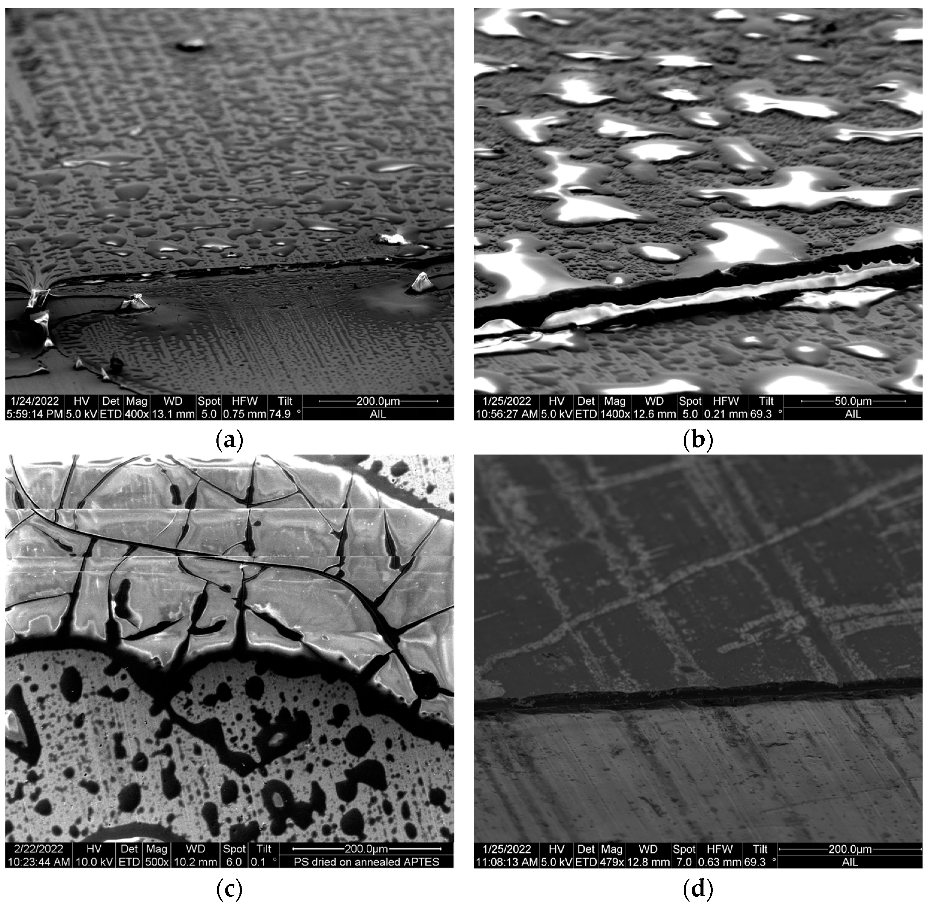
The SEM images in Figure 2 compare the topography of coating on the hydroxylated specimens with (a) polystyrene alone, (b) and (c) polystyrene top-coated on APTES, and (d) APTES alone, to characterize the differences between a dried polystyrene coating and cured APTES film. The thickness of each coating can be visualized by the step in each image, which was made by peeling a tape that was pre-applied to one side of the specimen before coating. The polystyrene coating exhibits the dewetting feature, as evidenced by the various shapes of islands, undulations, polygons, and drops unevenly distributed on the surface, as shown in Figure 2a,b. Detwettability is a function of the film’s thickness and its surface energy relative to the substrate [18]. As explained in [19], the morphologies exhibited here would be associated with capillary instability during the dewetting and drying process of the polystyrene on the substrate. Crazing was also observed in a dried polystyrene film, as shown in Figure 2c. Crazing is an exhibition of brittle fracture in glassy polymers that initiates in a certain stress regime [20]; for our case, the stress would be induced during physical gelation (chain entanglement) of polystyrene when the solvent acetone evaporates from the prepared polystyrene solution at ambient temperature. Crazing can also be related to the molecular weight of a polymer [21]. As opposed to the dewetting and ruptures on a dried polystyrene layer, the APTES-primed surface lacks a dewetting feature, as shown in Figure 2d. The APTES coating is so uniform that it reveals the groove-like pattern in the forging direction of the wrought aluminum alloy sheet.
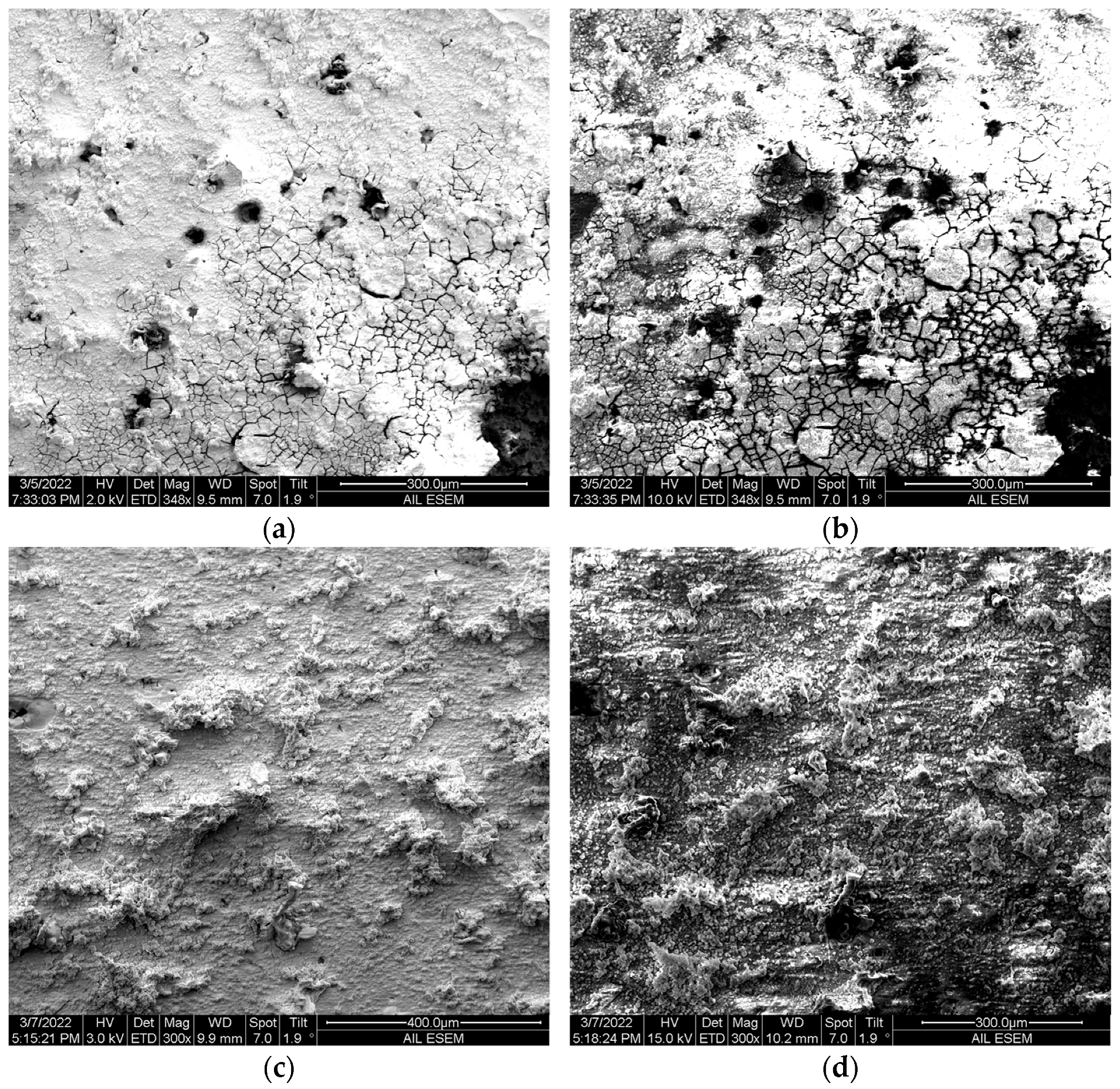
The role of the polystyrene coating as corrosion protection was further characterized by immersing the coated specimens in a 3.5 wt.% NaCl solution. SEM imaging was conducted on the specimens after seven days of immersion. The SEM was operated using the low- and high-energy electrons modes. The focused beam of electrons at a lower accelerating voltage can only penetrate to a relatively shadow depth of the plastic coating before dispersing to image the surface of a coating. The high-accelerating electrons can reach a deeper layer in a coating, which allows us to acquire information underneath the polystyrene coating. The image in Figure 3a shows the surface topography on a corrosively soaked PS-coated specimen taken at an accelerating voltage of 3 kV. The PS coating was not dissolved but deteriorated, as exhibited by holes of various sizes. These coating defects make the coating progressively permeable to the aqueous electrolyte, allowing corrosion to occur beneath the coating. With the imaging location and spot size unchanged but with a higher accelerating voltage of 10 kV, we acquired the condition beneath the coating, as shown in Figure 3b. Pitting predominates the imaged area beneath the coating layer; the mildly bumped surface exhibited in the coating layer is likely raised from the substrate by the corrosion products accumulated locally underneath the coating surface. The EDS images in Figure 3c,d show that the substrate was badly corroded, resulting in the loss of the major element, Al, in an electrochemical reaction with chloride ions. The corrosion products apparently precipitate at the rim of the circular, Cl-concentrated pits. Similar characteristics can be seen in the PS-APTES- and PS/APTES-coated specimens in Figure 4.

3.2. EIS Analysis Results

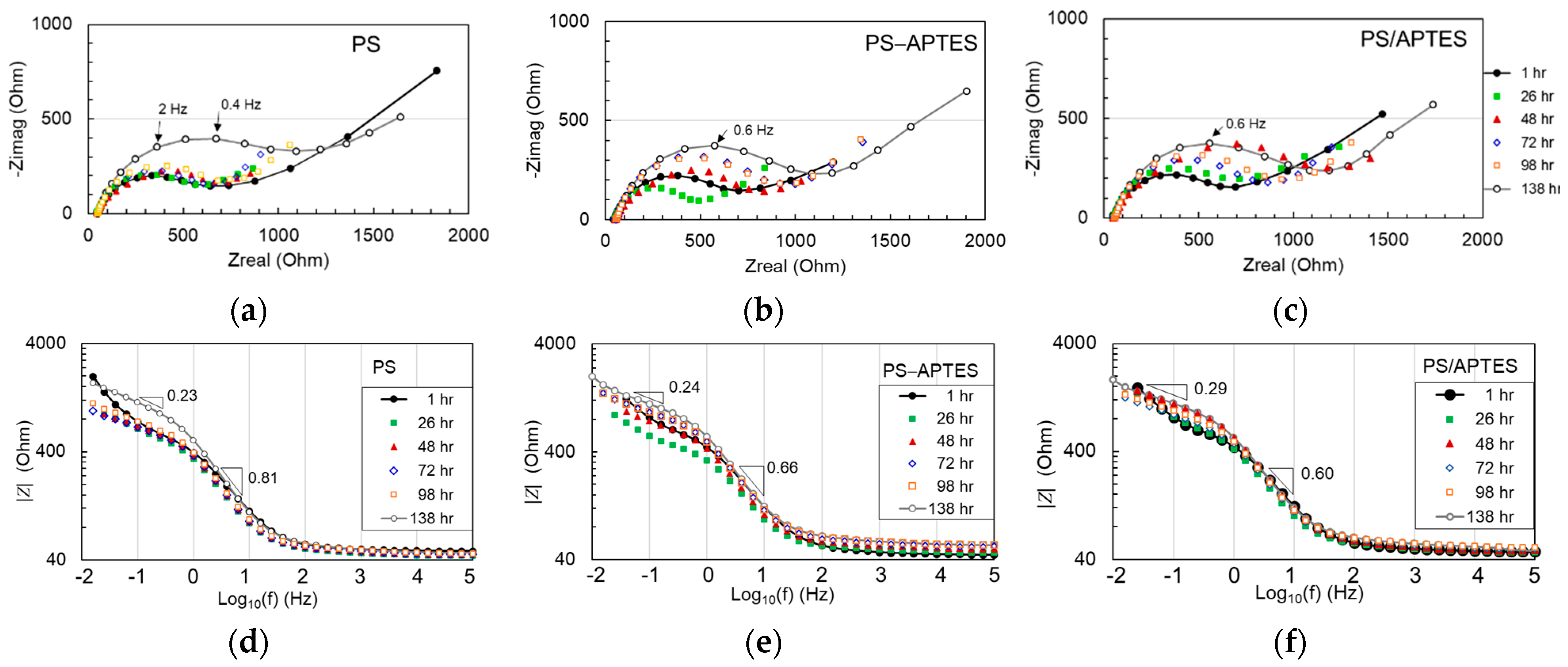
The EIS results are expressed in the Nyquist plots for each type of coated sample in Figure 5a–c. The curved portion of each plot is associated with charge transfer in the spectral range around 1 Hz (as labeled), while the “tail” portion implies diffusion. Impedance generally increased over time for all the specimens, but the change progressed differently.
The Bode plots of the EIS data are shown in Figure 5d–f. The Bode curves in the spectral region above 100 Hz are flat. This portion is associated with the ohmic resistance behavior of the specimen in corrosion. In a lower spectral range between 1 and 100 Hz, a capacitance feature is exhibited in all by a (negative) slope at 0.6–0.8 dB/dec. This spectral feature is associated with the coating layer and is typically modeled by a constant phase element (CPE). In the spectral range below 1 Hz, lines of less inclination of 0.2–0.3 dB/dec appear to predominate the Bode curves. This spectral range is associated with charge transfer and/or diffusion of ions in the double layer. The impedance of all tested specimens in the spectral range of 1 Hz or above increased over time yet fluctuated in the spectral region below 1 Hz. This phenomenon will be further explained with the failure mechanism associated with the double layer shortly.
The EIS data points were fitted to the equivalent circuit model in Figure 6. This model accounts for the ohmic resistance of the electrolyte (Rs), the impedance of the coating layer modeled by a CPE (Cc, m) and resistance Rc, and the impedance in the double layer ((Cdl, n) and charge transfer resistance Rct). Without losing generality, hereafter we refer to the CPE parameter, C, as capacitance. Fitted results and chi-squares are listed in Table 1. It is worth mentioning that, for our collected data, the fitting is not improved by adding a Warburg element next to the double-layer module.
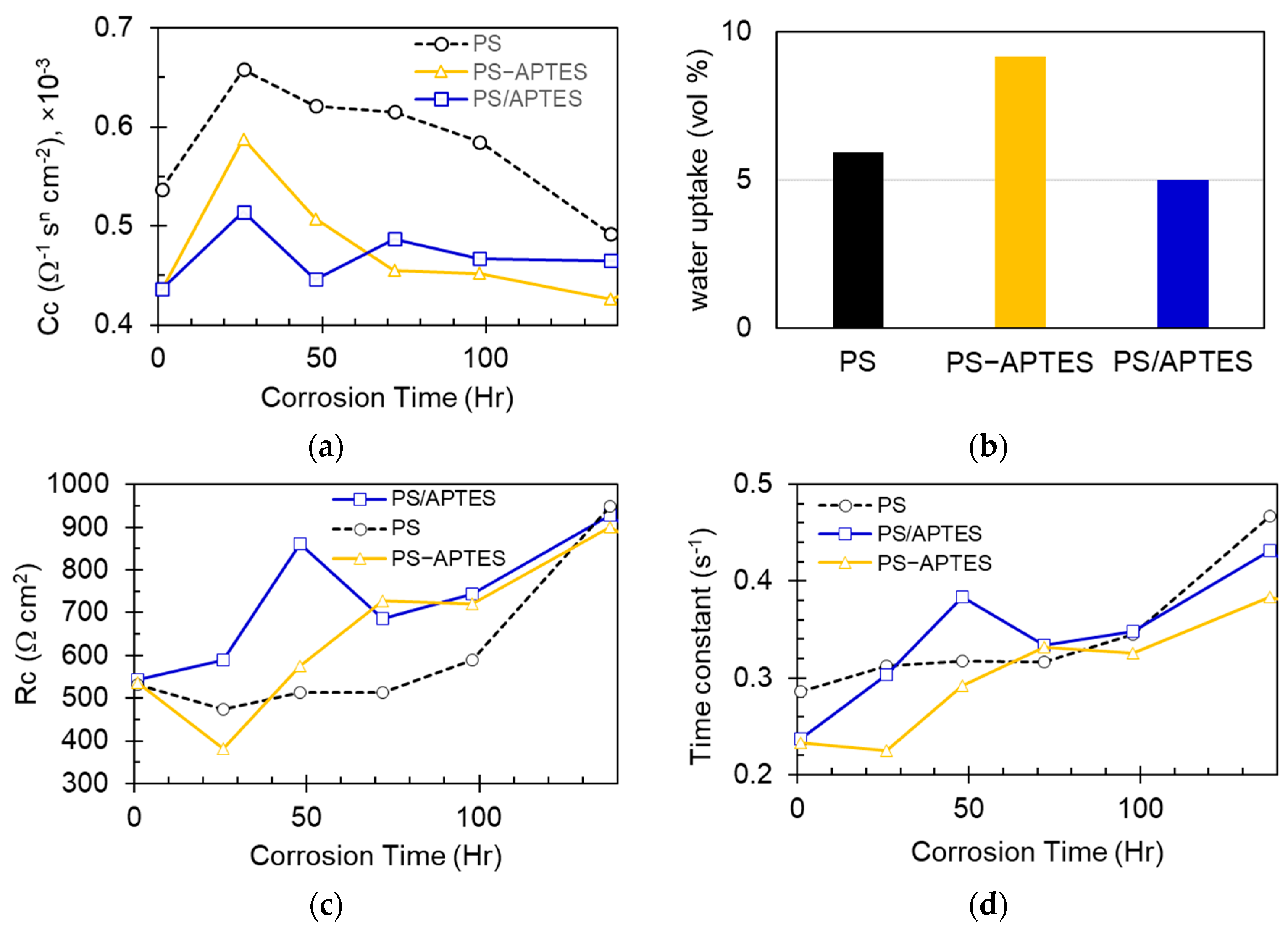
The values of Cc and Rc plotted in Figure 7 show that the PS-coated specimen has a larger Cc and smaller Rc than the PS-APTES and PS/APTES specimens over almost the entire period of testing. This implies that the PS coating has a smaller impedance than the PS-APTES and PS/APTES coatings. Such a result is expected because the primed APTES layer in the PS-APTES or PS/APTES coating not only physically provides an additional corrosion barrier, but also chemically enables a strong bonding to the hydroxylated substrate (aluminum oxide surface) that mitigates corrosion [11].

4. Failure Mechanisms

Based on the fitting of the EIS data, we suggest a few mechanisms to explain the change in impedance of the coated specimens.

4.1. Mechanism 1—Coating Loses Impedance to Water Uptake in the Early Stage

On the first day of corrosion, all coated specimens commonly experienced an increase in capacitance of the coating layer, Cc, as seen in Figure 7a. This is caused by water permeation into the coating layer through crazing in the dried polystyrene. Although the measured WCA indicates a hydrophobic surface on our prepared polystyrene coating, water still ingresses through the surface crazing (as seen in Figure 1) [18]. Because water has a permittivity of at least one order of magnitude larger than polymers, an aqueously soaked coating layer will increase its capacitance [19] and thus reduce the impedance.
The PS-APTES coated specimen exhibited the largest increase in Cc (1.53 × 10⁻⁴ Ω−1 sm cm−2 as calculated from the data listed in Table 1), as opposed to the smallest increase for the PS/APTES specimen (0.78 × 10⁻⁴ Ω−1 sm cm−2). The increase in Cc can be correlated to the extent of water uptake over the first day of immersion as follows. The water uptake is estimated by the Brasher–Kingsbury equation [20,21], which assumes that a coating layer of uniform thickness without swelling:
V w = 100 × log C / C 0 log ε a q / ε P S
where V w is the water uptake of a soaked coating (vol.%), C is the capacitance of a soaked coating, C 0 the capacitance of the coating when dry (which is approximated by the fitted capacitance at the 1 h mark), and ε a q and ε c are the permittivity of water and coating material, respectively. For our calculations, we adopted these values: ε a q = 80, ε c = 2.6 (polystyrene), ε c = 31 (graphene oxide/APTES composite) [22], and ε c = 3.1   (APTES). The calculated water uptake values show that the PS-APTES-coated specimen has the largest uptake, which is about 80% more than the least uptake in the PS/APTES-coated specimens, as shown in Figure 7b. Noted that the water uptake is correlated to the rate of change in the capacitance of a coating, as indicated by the slope of each Cc curve in Figure 7a. Such a correlation implies that the change in capacitance of a coating material is governed by the extent of water absorption in a coating layer, which in turn modifies its electrical permittivity [23].
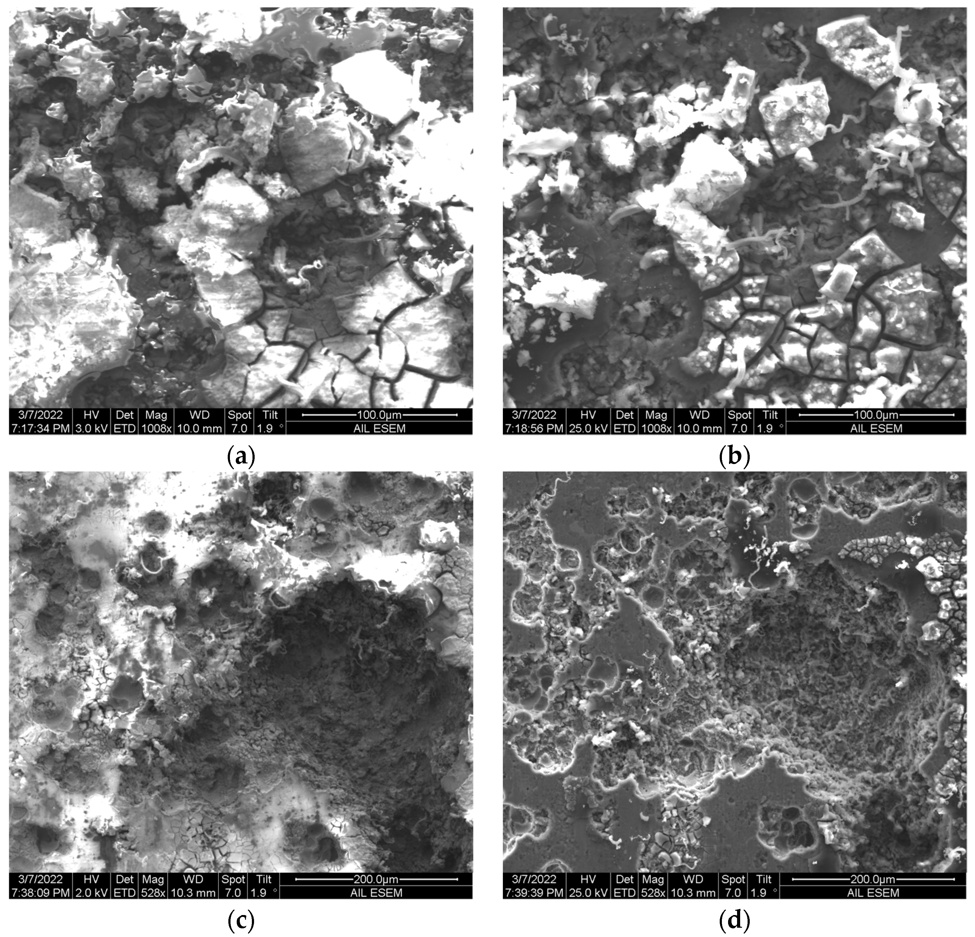
After the initial stage (one day) of soaking in the corrosion solution, the coating’s capacitance gradually decreased for all specimens, yet in different downtrends. The capacitance of the PS-APTES and PS/APTES coatings was relatively stable compared to that of the PS coating (Figure 7a). This can be attributed to the tightly polymerized APTES network versus the loose physical gelation of the PS layer on the substrate, as evident in the SEM images in Figure 8. The APTES layer offers two features that enable a better barrier under water attack, relatively strong molecular binding to the aluminum substrate (by the chemical reaction of the APTES’ ethoxy groups on the hydroxylated substrate surface) and a denser film formed as the applied APTES was polymerized.
Figure 7c shows the change in coating resistance, Rc, for each type of specimen. After the initial stage (one day) of corrosion, the coating becomes more resistant to ions passing. The uptrend change in Rc is possibly explained by the blockage of an ion’s transportation passages in the coating. The blockage can be attributed to the loosened part of the polystyrene and/or APTES retained in the coating layer; it can also be due to the accumulation of corrosion products near the substrate side of the coating.

4.2. Mechanism 2—Narrowing Passages in Porous Coating

The coating layer, as modeled by a first-order system in Figure 6, has an equivalent impedance formulated as:
Z c ω = R c / ( 1 + j R c C c ω )
Figure 7d shows the calculated values of R c C c , which is the time constant of this first-order circuit model. By comparing Figure 7c,d, there is a similar trend in the time-varying values of Rc and of RcCc. This suggests that the increased impedance in a coating layer is predominantly attributed to the increase in the resistance of the coating, which is due to the blocking or narrowing of the conductive passages in the coating. It is noted that the results in Figure 7 were obtained from an individual specimen for each type of coating, which may not be representative without an understanding of the statistical significance. However, all specimens were prepared and tested in the same batch under the same environmental conditions to eliminate unnecessary variations and bias in comparing the results.

4.3. Mechanism 3—Degraded Structural Integrity in Coating

At a later stage of corrosion, the coating gradually degrades under water attack. The polystyrene layer has a different degradation mode than that of the APTES layer. The PS-APTES and PS/APTES coatings exhibit better structural integrity than the PS coating. The additional APTES thin film primed between the substrate and the polystyrene layer, as well as the relatively tight APTES network, enhances corrosion protection.
In our case, the PS coating is structurally loose because it has been prepared by dissolving polymerized polystyrene powder flakes in a solvent for spin coating and then drying for 24 h to evaporate the solvent. Formation of the polystyrene during the drying process only involves physical gelation. The dried PS coating is weakly adhered to the substrate through Van der Waals forces [24]. The SEM images in Figure 8a,b show that crazing developed through the PS coating layer and widened toward the bottom of the coating, while some coating structure was loosened and collapsed into visible voids. This observation suggests that the PS coating loses its integrity to water permeation, reducing its effective area of conductance and resistance.
Water permeates more slowly into the APTES network than into the polystyrene. Typically, networked silanes detach in aqueous solutions by two modes, liberation of surface functionalized silane moieties (fast mode) [25,26] and the partial hydrolysis of the network in hydrolytically unstable silane layers (slow mode) [25]. Once a covalently networked site is detached from the surface silanol or siloxane bonds, water will eventually reach the non-fully connected sites (networking defects) buried in the silane network [27]. These defect sites are either isolated within the polymerized multilayers to degrade the cross-link [27] or> become the loosened portions of a cured APTES complex [13]> and can be easily hydrolyzed (water damage). It is noted that APTES can also naturally degrade without soaking in an aqueous solution, as the needed H2O molecules for hydrolysis can be sourced to the possible condensation of the molecular moieties from within the APTES structure [13]. Figure 8c,d show SEM images of the APTES-only coating near and below the surface at the same imaging location, as taken at different electron energy levels, after one week of immersion in the corrosion solution. Compared to the PS coating, the cured APTES exhibits a tight complex structure without visible cracks or voids. This observation can explain why the more structurally intact APTES film makes the capacitance in the PS-APTES and PS/APTES coating more stable than the PS coating, as shown in Figure 7a.

4.4. Mechanism 4—Double-Layer Adsorption Predominates Charge Transfer

After permeating the aluminum substrate, the aqueous corrosion solution was easily trapped there because the aluminum surface was treated with polar hydroxyl groups during our sample preparation. For our tested specimens, electrons predominantly took the electric path through CPE of the double layer to enable the electrochemical reactions (of corrosion). This can be explained by comparing the impedance of the CPE and resistor that were parallelly connected as a first-order system to model the double layer (Figure 6). In a typical double-layer model, the electrolyte ions diffuse through the porous coating layer to reach the substrate surface, where they are adsorbed to (desorbed from) the substrate in a process that favors thermodynamic stability. Some ions are directly adsorbed to the substrate while other (solvated) ions are separated from the substrate, thus forming a double layer. Charge transfer thus takes place in the double layer via two mechanisms: the Faradaic process, in which ions are in contact with the substrate to allow electron transfer, and the non-Faradaic process, in which ions adsorb to the electrode surface for progressive charging/discharging. The Faradaic process is governed by the resistance element of impedance Rct in our model, as opposed to the CPE for the non-Faradaic process. The impedance of the CPE has a magnitude 1 / ( C d l n ω ) ( n = 1 from Table 1). For our test results, the diffusion and charge transfer are characterized in the spectral range of 1 Hz or below (Figure 5). With this characteristic spectrum in mind, the impedance of the CPE is about one order of magnitude smaller than Rct after applying the fitted data of each sampling (Table 1). Therefore, we can deduce that the charge transfer is predominated by the adsorption mechanism at the coating/substrate interface. The mechanism of adsorption between the chloride ions and the aluminum oxide surface is detailed in [28,29].
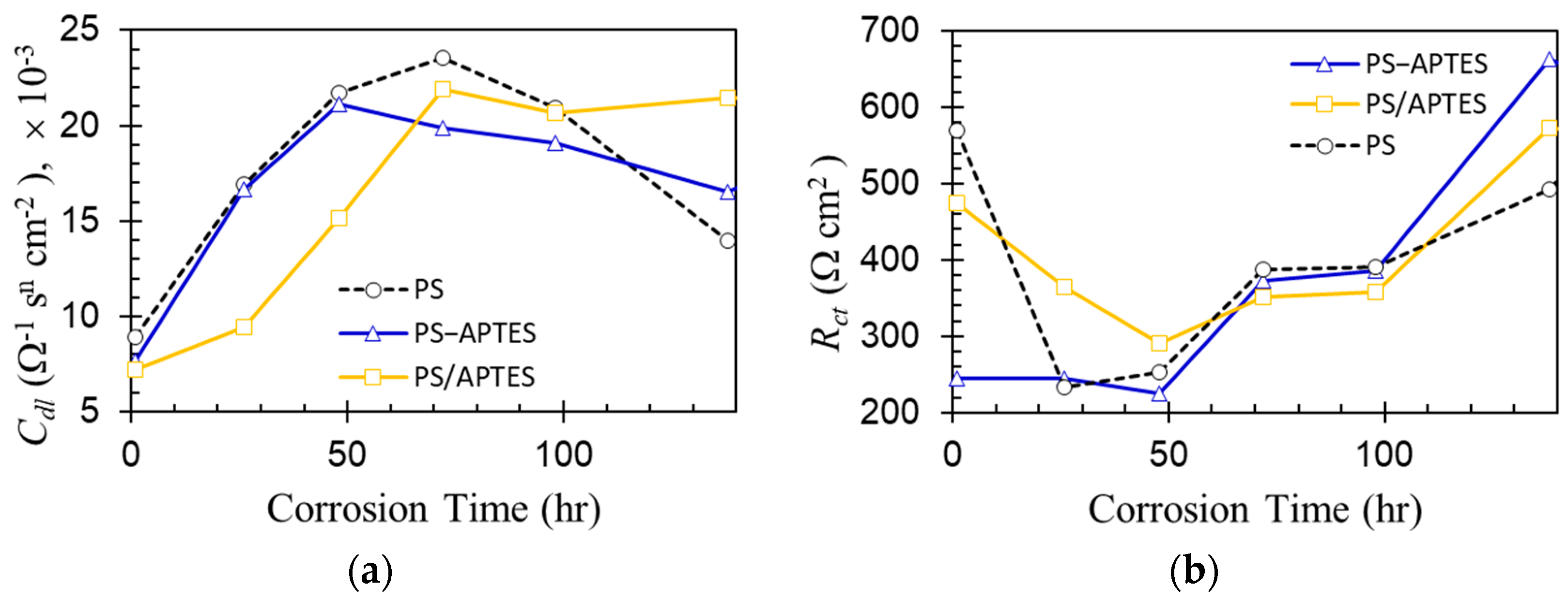
The double-layer impedance curves in Figure 9 exhibit two-stage characteristics with the 48 h mark as a milestone. Figure 9a shows an increasing double-layer capacitance over the first two days of corrosion for all coated specimens. In this stage, the double layer was built up, as ions channeled toward the substrate along with the progressive electrolyte wicking at the exposed substrate surface. The increasing double-layer capacitance may also be related to the thinning of the Debye length of the double layer in its build-up stage when the ions gradually concentrate there [30]. After reaching equilibrium, the double-layer capacitance began to decrease. This is possibly due to the loss of coating integrity (Mechanism 3) to water ingress at the coating/substrate interface, implying a possible delamination of the coating. Figure 9b shows that the charge transfer resistance Rct decreased during the early stage and then increased rapidly for all coated specimens. The decrease in Rct can be related to water ingress so that the coating/substrate interface becomes more conductive for the adsorbed ions to exchange their charges. The increase in Rct may be caused by corrosion activities that occur locally and unevenly—local pitting takes place mostly around the Cu-enriched sites for the APTES primed samples [11]—while the corrosion products form and distribute at the broken sites of the aluminum oxide layer under water attack [31].

5. Conclusions

This paper comparatively characterizes polystyrene coating as a corrosion barrier on hydroxylated aluminum alloy 2024-T3 of three different silane-primed surface conditions: a bare surface without priming (PS-coated), an APTES-primed surface with the silane in the process of curing (PS-APTES coated) or cured (PS/APTES coated). APTES, an organosilane, was introduced as a coupling agent to improve the adhesivity of polystyrene to aluminum alloy samples. All coated specimens have a similar extent of hydrophobicity. After exposure to a 3.5 wt.% NaCl solution, the polystyrene coating exhibited holes and cracks but still held its structural integrity. However, pitting corrosion undermined the substrate beneath the coating for all coated specimens. The electrochemical impedance spectroscopy results suggest that the coupling agent APTES makes the composite coating layer more electrically resistant than the PS coating alone. In the initial stage of immersion in the corrosion solution, all three types of coating tested lost their impedance due to water ingress, with the PS-coated being the most conductive. Later, they all experience a gain in impedance due to blocking or narrowing of the conductive passages in the coating. The structural integrity of the coating also degrades, yet the more structurally intact APTES film makes the PS-APTES and PS/APTES coatings more stable in water permeation than the PS coating. In the final stage of corrosion, our EIS fitted results show that, for the double layer, CPE’s impedance is ten times smaller than the charge transfer resistance. This suggests that charge transfer in the double layer predominantly takes the electric path through CPE, which can be associated with the adsorption of ions at the coating/substrate interface.

Funding

This research was supported by the NASA EPSCoR Program Cooperative Agreement Notice (CAN) (80NSSC20M0137).

Data Availability Statement

Raw EIS data are archived and accessible at https://sites.google.com/a/alaska.edu/cf-chen/home/organic-inorganic-coating (accessed on 15 June 2023).

Acknowledgments

The SEM imaging was performed at the Advanced Instrumentation Laboratory (AIL), University of Alaska Fairbanks.

Conflicts of Interest

The author declares no conflict of interest.

References

  1. Románszki, L.; Datsenko, I.; May, Z.; Telegdi, J.; Nyikos, L.; Sand, W. Polystyrene films as barrier layers for corrosion protection of copper and copper alloys. Bioelectrochemistry 2014, 97, 7–14. [Google Scholar] [CrossRef] [PubMed]
  2. Peng, J.; Xing, R.; Wu, Y.; Li, B.; Han, Y.; Knoll, W.; Kim, D.H. Dewetting of thin polystyrene films under confinement. Langmuir 2007, 23, 2326–2329. [Google Scholar] [CrossRef] [PubMed]
  3. Zhang, J.; Zhang, L. Polystyrene/TiO2 Nanocomposite Coatings to Inhibit Corrosion of Aluminum Alloy 2024-T3. ACS Appl. Nano Mater. 2019, 2, 6368–6377. [Google Scholar] [CrossRef]
  4. Alangari, A.M.; Al Juhaiman, L.A.; Mekhamer, W.K. Enhanced Coating Protection of C-Steel Using Polystyrene Clay Nanocomposite Impregnated with Inhibitors. Polymers 2023, 15, 372. [Google Scholar] [CrossRef]
  5. Raju, A.; Lakshmi, V.; Prataap, R.V.; Resmi, V.; Rajan, T.; Pavithran, C.; Prasad, V.; Mohan, S. Adduct modified nano-clay mineral dispersed polystyrene nanocomposites as advanced corrosion resistance coatings for aluminum alloys. Appl. Clay Sci. 2016, 126, 81–88. [Google Scholar] [CrossRef]
  6. Amirshaqaqi, N.; Salami-Kalajahi, M.; Mahdavian, M. Corrosion behavior of aluminum/silica/polystyrene nanostructured hybrid flakes. Iran. Polym. J. 2014, 23, 699–706. [Google Scholar] [CrossRef]
  7. North, S.H.; Lock, E.H.; Cooper, C.J.; Franek, J.B.; Taitt, C.R.; Walton, S.G. Plasma-based surface modification of polystyrene microtiter plates for covalent immobilization of biomolecules. ACS Appl. Mater. Interfaces 2010, 2, 2884–2891. [Google Scholar] [CrossRef]
  8. Chen, C.-F.; Baart, B.V.; Zhang, J.; Zhang, L. Polystyrene/TiO2 nanocomposite coating for strength and toughness enhancement of aluminum alloy 2024-T3 in accelerated stress corrosion cracking. Prog. Org. Coat. 2021, 161, 106458. [Google Scholar] [CrossRef]
  9. Witucki, G.L. A Silane Primer: Chemistry and Applications of AIkoxy Silanes. J. Coat. Technol. 1993, 65, 57–60. [Google Scholar]
  10. Alghunaim, A.; Brink, E.T.; Newby, E.Y.; Newby, B.-M.Z.; Huttenlochner, K.; Müller-Renno, C.; Ziegler, C.; Merz, R.; Merz, B.; Kopnarski, M.; et al. Retention of poly (N-isopropylacrylamide) on 3-aminopropyltriethoxysilane. Biointerphases 2017, 12, 02C405. [Google Scholar] [CrossRef]
  11. Hintze, P.E.; Calle, L.M. Electrochemical properties and corrosion protection of organosilane self-assembled monolayers on aluminum 2024-T3. Electrochim. Acta 2006, 51, 1761–1766. [Google Scholar] [CrossRef]
  12. van Ooij, W.J.; Zhu, D.; Stacy, M.; Seth, A.; Mugada, T.; Gandhi, J.; Puomi, P. Corrosion protection properties of organofunctional silanes—An overview. Tsinghua Sci. Technol. 2005, 10, 639–664. [Google Scholar] [CrossRef]
  13. Smith, E.A.; Chen, W. How to prevent the loss of surface functionality derived from aminosilanes. Langmuir 2008, 24, 12405–12409. [Google Scholar] [CrossRef] [PubMed]
  14. Choi, S.-H.; Zhang Newby, B.-m. Suppress polystyrene thin film dewetting by modifying substrate surface with aminopropyltriethoxysilane. Surf. Sci. 2006, 600, 1391–1404. [Google Scholar] [CrossRef]
  15. Redon, C.; Brochard-Wyart, F.; Rondelez, F. Dynamics of dewetting. Phys. Rev. Lett. 1991, 66, 715. [Google Scholar] [CrossRef]
  16. Reiter, G. Unstable thin polymer films: Rupture and dewetting processes. Langmuir 2002, 9, 1344–1351. [Google Scholar] [CrossRef]
  17. Reiter, G. Dewetting of thin polymer films. Phys. Rev. Lett. 1992, 68, 75. [Google Scholar] [CrossRef]
  18. Reichlin, J.; Bormashenko, E.; Sheshnev, A.; Pogreb, R.; Shulzinger, E.; Katzir, A. Investigation of water penetration in polystyrene by use of polymer-coated AgClBr fibers and development of new sensor intended for the FEWS spectroscopy of organic compounds in water. In Proceedings of the SPIE—The International Society for Optical Engineering, San Diego, CA, USA, 30 July–4 August 2020; SPIE: Bellingham, WA, USA, 2000; pp. 305–313. [Google Scholar]
  19. van Westing, E.; Ferrari, G.; de Wit, J. The determination of coating performance with impedance measurements-I. Coating polymer properties. Coating polymer properties. Corros. Sci. 1993, 34, 1511–1530. [Google Scholar] [CrossRef]
  20. Brasher, D.M.; Kingsbury, A.H. Electrical measurements in the study of immersed paint coatings on metal. I. Comparison between capacitance and gravimetric methods of estimating water-uptake. J. Appl. Chem. 1954, 4, 62–72. [Google Scholar] [CrossRef]
  21. Sykes, J.M. A variant of the Brasher-Kingsbury equation. Corros. Sci. 2004, 46, 515–517. [Google Scholar] [CrossRef]
  22. Zhi, X.; Mao, Y.; Yu, Z.; Wen, S.; Li, Y.; Zhang, L.; Chan, T.W.; Liu, L. γ-Aminopropyl triethoxysilane functionalized graphene oxide for composites with high dielectric constant and low dielectric loss. Compos. Part A Appl. Sci. Manuf. 2015, 76, 194–202. [Google Scholar] [CrossRef]
  23. Margarit-Mattos, I.C.P.; Agura, F.A.R.; Silva, C.G.; Souza, W.A.; Quintela, J.P.; Solymossy, V. Electrochemical impedance aiding the selection of organic coatings for very aggressive conditions. Prog. Org. Coat. 2014, 77, 2012–2023. [Google Scholar] [CrossRef]
  24. Esser, P. Principles in adsorption to polystyrene. Thermo Sci. Nunc Bull. 1988, 6, 1–5. [Google Scholar]
  25. Etienne, M.; Walcarius, A. Analytical investigation of the chemical reactivity and stability of aminopropyl-grafted silica in aqueous medium. Talanta 2003, 59, 1173–1188. [Google Scholar] [CrossRef]
  26. Wang, G.; Yan, F.; Teng, Z.; Yang, W.; Li, T. The surface modification of silica with APTS. Prog. Chem. 2006, 18, 238. [Google Scholar]
  27. Howarter, J.; Youngblood, J. Optimization of silica silanization by 3-aminopropyltriethoxysilane. Langmuir 2006, 22, 11142–11147. [Google Scholar] [CrossRef]
  28. Zhang, C.-H.; Liu, M.; Jin, Y.; Sun, D.-B. The corrosive influence of chloride ions preference adsorption on α-Al2O3 (0 0 0 1) surface. Appl. Surf. Sci. 2015, 347, 386–391. [Google Scholar] [CrossRef]
  29. Sundar, A.; Chen, G.; Qi, L. Substitutional adsorptions of chloride at grain boundary sites on hydroxylated alumina surfaces initialize localized corrosion. Npj Mater. Degrad. 2021, 5, 18. [Google Scholar] [CrossRef]
  30. Oldham, K.B. A Gouy–Chapman–Stern model of the double layer at a (metal)/(ionic liquid) interface. J. Electroanal. Chem. 2008, 613, 131–138. [Google Scholar] [CrossRef]
  31. Salmeron, M.; Bluhm, H.; Tatarkhanov, M.; Ketteler, G.; Shimizu, T.K.; Mugarza, A.; Deng, X.; Herranz, T.; Yamamoto, S.; Nilsson, A. Water growth on metals and oxides: Binding, dissociation and role of hydroxyl groups. Faraday Discuss. 2008, 141, 221–229. [Google Scholar] [CrossRef]
Figure 1. Water contact angles measured on the coating surface.
Solids 04 00016 g001
Figure 2. (a) Polystyrene coating on AA2024-T3. (b) Polystyrene coating on APTES-primed surface of AA2024-T3. (c) Ruptures in dried polystyrene film. (d) APTES coating on AA2024-T3. The step in the images was made by peeling a tape that had been applied at one side of the specimen before coating. Images tilted to better reveal the topographic features of coating.
Solids 04 00016 g002
Figure 3. PS-coated specimen in 3.5 wt.% NaCl solution. (a) SEM images of surface topography of coating imaged at a lower accelerating voltage. At the same location: (b) A “deeper” view of the coating imaged at a higher accelerating voltage. (c,d) EDS images of element Al and Cl.
Solids 04 00016 g003
Figure 4. SEM images of coated specimens in 3.5 wt.% NaCl solution. (a,b) PS-APTES specimen. (c,d) PS/APTES specimen. (a,c) Surface topography of the coating imaged at a lower accelerating voltage. (b,d) A “deeper” view of the coating at the same location, imaged at a higher accelerating voltage.
Solids 04 00016 g004
Figure 5. Measured impedance data in (ac) Nyquist plots and (df) Bode plots with calculated slopes (dB/dec).
Solids 04 00016 g005
Figure 6. Equivalent circuit model.
Solids 04 00016 g006
Figure 7. (a) Capacitance of coating. (b) Calculated water uptake for each type of coated specimens in the first day of immersion in the electrolyte. (c) Resistance of coating. (d) Time constant of coating layer’s impedance model.
Solids 04 00016 g007
Figure 8. SEM images of PS coating (a,b) and APTES-only coating (c,d) taken at a lower accelerating voltage (a,c) versus at a higher accelerating voltage (b,d) at the same location. Images taken of coated specimens after one week of immersion in NaCl 3.5 wt.% solution.
Solids 04 00016 g008
Figure 9. Double-layer capacitance (a) and charge transfer resistance (b).
Solids 04 00016 g009
Table 1. Fitted parameters of the equivalent circuit model for coated samples tested.
Time
(h)
CoatingRs
(Ω cm2)
Rc
(Ω cm2)
Cc
−1 sm cm−2)
mRct
(Ω cm2)
Cdl
−1 sn cm−2)
nχ2 (×10−3)
1PS385325.37 × 10−40.825698.92 × 10−3112.8
PS-APTES365364.35 × 10−40.802457.68 × 10−315.5
PS/APTES385434.36 × 10−40.804757.19 × 10−317.8
26PS355506.58 × 10−40.8226216.90 × 10−313.3
PS-APTES383825.88 × 10−40.8224516.64 × 10−314.8
PS/APTES385905.14 × 10−40.832539.43 × 10−314.8
48PS375126.21 × 10−40.8325321.72 × 10−313.7
PS-APTES415755.07 × 10−40.8322521.13 × 10−313.7
PS/APTES408604.46 × 10−40.8229015.16 × 10−315.1
72PS375146.15 × 10−40.8338723.57 × 10−312.9
PS-APTES437284.55 × 10−40.8337319.86 × 10−314.4
PS/APTES426864.87 × 10−40.8235121.92 × 10−314.7
98PS385895.85 × 10−40.8239020.95 × 10−313.0
PS-APTES457204.52 × 10−40.8338619.06 × 10−314.0
PS/APTES437244.67 × 10−40.8235820.65 × 10−314.2
138PS389494.92 × 10−40.8149213.98 × 10−313.6
PS-APTES459004.26 × 10−40.8266316.50 × 10−314.7
PS/APTES419274.65 × 10−40.8057321.43 × 10−319.6
Disclaimer/Publisher’s Note: The statements, opinions and data contained in all publications are solely those of the individual author(s) and contributor(s) and not of MDPI and/or the editor(s). MDPI and/or the editor(s) disclaim responsibility for any injury to people or property resulting from any ideas, methods, instructions or products referred to in the content.