Article

Meta-Material Layout for the Blast Protection of Above-Ground Steel Pipes

by
Miltiadis Kontogeorgos
1,2,* and
Clemente Fuggini
2
1
School of Civil Engineering, National Technical University of Athens, 15780 Athens, Greece
2
Rina Consulting S.p.A., Via Gran S. Bernardo Palazzo R, 20089 Rozzano, Italy
*
Author to whom correspondence should be addressed.
Geotechnics 2023, 3(3), 584-600; https://doi.org/10.3390/geotechnics3030032
Submission received: 17 May 2023 / Revised: 5 June 2023 / Accepted: 28 June 2023 / Published: 1 July 2023

Abstract

:
The current study investigates the capacity of the proposed meta-material layout for the blast protection of above-ground steel pipes against explosions. The philosophy of the meta-material layout’s design is described adequately, and the 1D periodic structures’ theory is adopted for the analytical prediction of the layout’s band-gaps. The special characteristics of the blast loading are explained, and specific time-related parameters are calculated. The layout is tested numerically for nine explosion scenarios of various magnitude via the finite element program ABAQUS, and the CONWEP model is selected for the simulation of the explosions. The results demonstrate a significant reduction in the maximum displacements developed on the pipe’s spring line and crown within a blast loading. This study composes an extension of the author’s previous research on buried steel pipes and surface explosion, advancing now the applicability of the meta-material layouts for the cases of above-ground steel pipes towards explosions and blast hazards. The outer goal is the investigation and the further spreading of the beneficial exploitation of meta-materials concepts for the scope of the pipelines’ effective blast protection, readdressing that this way is a major hazard for this type of structure and a gap in the current literature.

1. Introduction

The emergence of Critical Infrastructures (CIs) as a significant factor and cornerstone for the well-tempered function of states and communities is becoming more and more crucial. The energy demands of cities and countries are increasing on an annual basis, highlighting that this way is a vital and strategic role for Energy Infrastructures (EIs). As the hostility of the surrounding geopolitical environment is globally intensified, CIs and EIs are frequently considered as targets for attacks and disruption events. Their interconnection and interdependency expose their vulnerabilities more intensively and distinctively. Due to this configured landscape and under the pressure of the economic impact and the safety issues induced by these disruptive events, states and governments are developing and adopting resiliency frameworks [1,2,3] for the efficient protection of CIs and EIs. These synchronized actions serve the goal of enhancing the capacity of the CIs and EIs to withstand and recover from these events and therefore their subsequent effects to be mitigated. To this ambition and direction, the exploitation of the meta-materials can provide solutions of high value, especially towards the blast protection of the CIs and EIs.
The conceptualization and development of meta-materials for the purposes of civil engineering practice and problems are relatively recent (within the previous decade). The description of the meta-materials’ wave attenuation mechanisms and the investigation of the enhanced behavior that they exhibit in the frequency field were presented in [4,5] for mass-in-mass modeling and in [6] for periodic materials. The dispersion differences and consistency of artificial periodic structures in general and by deepening into complex dispersion relations were examined also [7]. The primal focus in the design of meta-materials for civil engineering applications was funneled towards the anti-seismic protection of buildings and structures. Among the first developed meta-material concepts in this direction was the 1D layered periodic foundation, which consisted of concrete and rubber components [6,8,9], and experimental results validated its enhanced performance towards seismic excitation and loading [6,10]. The extension of the specific concept in the two-dimension [11] and three-dimension [12] wavefields followed later, also taking into consideration the soil–structure interaction [13] and the impact of geometrical parameters on the characteristics of the attenuation zones [14]. Applications of this concept included the dynamic responses of a multi-story frame building [15] and the seismic response reduction in bridges [16]. The development of a non-linear periodic foundation for the same purpose has been conducted recently [17], placing roller bearings between the concrete layers of the foundation. The contribution of the meta-material concepts to the enhancement of the response of EIs towards seismic hazards was demonstrated via the concept of the meta-foundation [18,19], which was designed for the protection of fuel and liquid storage tanks, showing great results also at the experimental level [20]. Another concept related to geotechnical engineering was the periodic piles barrier. The attenuation of the shear plane waves in saturated soil due to the presence of periodic piles barriers was verified [21,22,23], along with their filtering property under moving loads [24] and the Rayleigh wave isolation they can provide in a poroelastic half-space [25]. Regarding the field of transportation geotechnics, concepts, like meta-barrier for the attenuation of plane waves [26], periodic layered slab track for reduction in vibrations caused by rail transit [27], periodic trench barriers [28,29] and periodic piles barriers [30] for ground vibration mitigation and isolation, were developed also. Recently, machine learning methods were exploited for the more accurate design of meta-materials concepts, including neural networks for a more precise calculation of the attenuation zones [31] and deep learning for the topology design of periodic barriers [32].
The ability of the meta-materials to mitigate the impact of dynamic nature hazards was investigated and tested also against the blast phenomena. In this field, the concept of meta-concrete, in which lead spheres were coated with soft materials and embedded into the concrete [33], was pioneering and was validated experimentally [34,35,36]. The capacity of finite-sized meta-concrete towards shock mitigation [37] and its stress wave attenuation towards impulsive loadings [38] were studied, along with the response of locally resonant concrete structures [39] and of meta-concrete beams under blast load [40], extended also at the experimental level [41]. The influence of the design parameters [42] and the effect of an enhanced coating layer [43] on the band-gap formulation and the response of the meta-concrete were described. More recent expressions of meta-concrete are found in [44], where the performance of a meta-concrete slab having embedded dual-resonant aggregate is evaluated, and in [45], where the response of meta-concrete panels subjected to an explosive load is studied. Another type of meta-materials concept for the same scope is a meta-sandwich panel, which was a previously proved idea for energy absorption [46] and blast protection [47,48], but is now examined and extended under the prism of the meta-materials theory. Meta-panels using single or multiple types of resonators and acting as sacrificial claddings for blast energy were developed and proposed in [49,50,51]. The contribution of the viscous damping on composite meta-panels of resonators embedded in the core under blast load was examined in [52], and the experimental validation of the meta-panels’ impact mitigation capability was conducted [53]. Various other concepts were developed within the broader field of meta-materials for the same scope. Among them are plate-like meta-structures for explosions’ vibration attenuation [54], resonant structures in resin matrixes for the mitigation of blast waves [55], elastic meta-materials for blast wave impact mitigation considering non-linearity [56,57], negative effective mass [58] and locally resonant woodpile meta-materials for impact and blast mitigation [59]. Despite the significant interest in the development of meta-material concepts for structures’ blast protection, a gap in the designing of meta-materials specifically for EIs and pipelines is observed. A first step towards covering this knowledge gap can be considered the previous work of the authors on the investigation of meta-material layouts’ exploitation for the blast protection of buried steel pipes against surface explosions [60].
The current landscape on the study of above-ground pipelines’ blast protection is focusing more on the risk assessment of explosion scenarios [61,62,63] and analyses of the natech-induced leakage incidents [64,65], which can lead to explosion scenarios. Research interest was not focused on the blast-resistant design of the pipelines, but mostly on that of buildings and other structures (e.g., bridges). The main challenges of the effective blast protection of buildings were identified [66], and special guidelines for the design of blast-resistant buildings [67,68] were suggested. Advanced material solutions were developed for this goal, including fiber-reinforced polymers (FRPs) and composite materials for the blast protection of structural elements [69,70,71], retrofitting materials for enhanced blast performance [72] and high energy-absorbing materials [73]. Other advanced materials can be considered, including ultra-high-performance concrete under impact loading [74,75,76], hybrid-reinforced concrete [77] and reinforced concrete beams strengthened with carbon fiber-reinforced polymer [78]. The impact performance of precast segmental columns [79,80,81] and beams [82] was under extensive research, also at the experimental level [83,84,85]. The idea of wrapping materials around concrete beams and columns for the enhancement of their impact response has been flourishing recently. In this direction, the impact resistance of FRP-based solutions was tested and proven themselves, including the wrapping of concrete beams with glass FRPs [86] or flax FRPs [87] and of concrete columns with FRPs [88,89]. This practice is closer to the solution considered in this study, but it is used on this or other forms only for concrete structures so far. But the literature landscape is showing a great disproportion in the studies both on the impact performance and the development of mitigation solutions for blast loading between the pipelines and the rest of the types of ground and above-ground structures (e.g., buildings and bridges). A similar gap in the literature exists between buried pipelines and underground structures [60].
The current study investigates the ability of the proposed meta-material layout to effectively protect above-ground pipelines against small- and medium-sized explosion scenarios. The investigation focuses on the maximum displacements experienced within the positive phase of a blast loading. This work is a follow-up of the authors’ previous research on the implementation of the same meta-material layout for the protection of buried steel pipes against surface explosions [60].

2. Background

2.1. Simplification of the Analytical Simulation Model for the Calculation of Band-Gaps

The notion of meta-materials strongly relies on their key ability to demonstrate “blind” zones for specific frequency ranges of transmitted waves, the so-called band-gaps. The existence of the band-gaps results in the mitigation or even the denial of transmission to the waves of those frequencies, protecting the underlying structure from the dynamic nature hazard. Therefore, the definition of the band-gaps’ frequency ranges, which mainly depends on the selection of the component material and the geometric characteristics of the proposed meta-material, is of high importance. The main frequency field of the hazards guides the design of the meta-materials, as the creation of band-gaps within these frequency fields composes the goal.
The form of the pressure loading on the pipe due to free-air burst explosions determines towards which dimension and direction the meta-material layout will be designed to perform. The adopted analytical model is presented schematically in Figure 1 and it is similar to the ones proposed in [60,90] for the problems of surface explosions and pressure loading on underground structures. The free-air burst explosion generates blast waves which impact the pipe and can be considered 1D shear (S) waves, transmitting towards the radial direction and applied vertically to its outer part. This simplification is based on the assumption that the vertical component of the blast wave is of highest contribution to the total damage induced. Regarding the adopted methodology for the calculation of the band-gaps (which is analyzed in the next chapter), the specific simplification was deemed necessary. No analytical calculation of pressures or stresses based on this model was taken into consideration.

2.2. Blast Loading

A definition for explosions can be given as a large-scale, rapid, and sudden release of energy [69,91]. The detonation of a condensed high explosive material generates hot gases under pressure which expand and release the volume they occupied, formulating blast waves [69,91]. The blast wave immediately reaches maximum pressure (usually referred as peak pressure) and then diminishes as a shock wave expanding outwards from the explosion source, creating after a short time a vacuum of sucked air and—along with the high intensity suction of winds—carrying debris for long distances away from the explosion source [91].
The profiling of the blast loads and the subsequent pressures induced are of high importance for examining their impact on the structures. The duration of the generated blast wave is only some mili- or micro-seconds, and the dynamic loading is characterized by high magnitudes, very high frequency ranges and impulsive natures (i.e., high magnitude pressure for short duration) [92]. A typical profile for a pressure–time history of a blast loading on a structure is given in Figure 2.
After the detonation of the explosives at t = 0 s, the shockwaves are traveling along, and the time demanded for the shockwaves to strike the structure is known as arrival time (tA). At this point, the pressure of the blast wave remains equal to the ambient atmospheric pressure Po and then increases almost spontaneously, reaching the maximum overpressure (max P) [92]. The pressure–time history is divided then into the positive and negative phases of the blast loading. The positive phase begins after the reach of the peak pressure and signifies the gradual decay of the pressure until the value of the ambient atmospheric pressure at t = to. After this point, the negative phase follows until t = to. The pressures further reduce and reach negative values of far less absolute magnitude, resulting in the suction effect of the blast wave and the blow away of the structure to the opposite direction than those of incident waves [67]. The most destructive part of a blast loading for the structures is considered the positive phase, where the biggest amount of the energy is released.

Blast Loading Time Parameters

The time parameters are very crucial for the accurate calculation of the blast loading, especially the to. Various expressions have been developed over time for their definition based on the stand-off distance (i.e., the distance between the explosion source and the structure). The stand-off distance affects many characteristics of the blast loading; since, whenever it increases, the positive phase also increases but in reduced amplitude [91]. One common method for defining the time parameters of a blast loading is proposed by [93]. For the implementation of this method, the calculation of the dimensional scaled distance according to the Hopkinson–Cranz law is need, as shown in Equation (1).
Z = R W 3
where R is considered the distance from the detonation source to the point of interest [m], and W is the weight (mass) of the explosives [kg].
For the definition of the tA and to, which are used in this study for the proper preparation of the explosion case scenarios, the method [93] is proposing is used, as shown in Equations (2) and (3).
t A = aW 1 3  
t o = bW 1 3
where a and b are coefficients related to the W and are considered from the respective diagrams (suggested in [94] and modified from [93]), and W ranges from 0 to 50 (usually for explosions far from the structure) [93].

3. Methodology and Materials

3.1. Periodic Materials Theory

A periodic structure of infinite layers (Figure 3a) is assumed, with the materials A and B set periodically forming this type of structure. The periodicity of the structure allows for the study of the formulation of the band-gaps for the whole structure via the examination of the so-called unit cell (Figure 3b), a typical cell consisting of two layers each with different materials. The propagation of the elastic waves towards the theoretically infinite, periodic structure and the boundary conditions between the composite materials are then exploited within the 1D periodic materials theory.
If the component of displacement in the y direction is expressed via u (z,t), and by assuming an elastic wave propagating along direction z, then the equation of motion (Equation (4)) in each layer can be expressed as [6]
2 u i t 2 = C i 2 2 u i z i 2
where u i represents the vertical displacement in each layer, and C i is, respectively, the shear ( C t ) or the longitudinal ( C p ) wave velocity of each layer.
Equation (5) is considered to be the general solution of Equation (4), leading also to the definition of the shear stress (τ) equation (Equation (6)).
u i ( z i ) = A i sin ( ω z i C ti ) + B i cos ( ω z i C ti )  
τ i ( z i ) = μ i u i z i = μ i ω [ A i cos ( ω z i C ti ) B i sin ( ω z i C ti ) ] / C ti
where ω is considered the angular frequency, and A i ,   B i are unknown constants related to the amplitude of each layer’s oscillation.
The boundary and continuity conditions are exploited then for the determination of the four unknown constants (A1, A2, B1 and B2), divided into two groups of two for each respective layer. The boundary conditions refer to the layers’ interfaces, under the assumption of perfect bond between them, and to the local co-ordinate systems Y1-Z1 and Y2- Z2. The continuity conditions in the interface between the layers are expressed via Equations (7) and (8), while the periodic conditions (based on the exploitation of the Bloch–Floquet theorem) are expressed from Equations (9) and (10) [6]. The u1(h1) and u2(h2) refer to the displacement in the top interface of materials A and B, respectively, while u1(0) and u2(0) refer to the displacement in the bottom interface of materials A and B. The same references apply, respectively, for the boundary conditions related to the shear stress τ.
u 1 ( h 1 ) = u 2 ( 0 )
τ 1 ( h 1 ) = τ 2 ( 0 )
u 1 ( 0 ) e ikh = u 2 ( h 2 )
τ 1 ( 0 ) e ikh = τ 2 ( h 2 )
where h i is considered the thickness of each layer, respectively, h is the total thickness of the unit cell (h = h1 + h2) and k is the wavenumber
Substituting Equations (5) and (6) into Equations (7)–(10), the four equations can be written in a matrix form as
[ sin ( ω h 1 C t 1 ) cos ( ω h 1 C t 1 ) 0 1 μ 1 C t 2 cos ( ω h 1 C t 1 ) μ 1 C t 2 sin ( ω h 1 C t 1 ) μ 2 C t 1 0 0 e ikh sin ( ω h 2 C t 2 ) cos ( ω h 2 C t 2 ) μ 1 C t 2 e ikh 0 μ 2 C t 1 cos ( ω h 2 C t 2 ) μ 2 C t 1 sin ( ω h 2 C t 2 ) ] [ A 1 B 1 A 2 B 2 ] = 0
For the existence of a non-trivial solution, the determinant of the co-efficient matrix must be equal to zero. Also, considering the expression for the shear wave velocity ( C t = μ ρ ) for simplification reasons, an expression of ω as a function of k (Equation (12)) is given [6], known as a dispersion relationship:
cos ( k × h ) = cos ( ω h 1 C t 1 ) cos ( ω h 2 C t 2 ) 1 2 ( ρ 1 C t 1 ρ 2 C t 2 + ρ 2 C t 2 ρ 1 C t 1 ) sin ( ω h 1 C t 1 ) sin ( ω h 2 C t 2 )
Exploiting the dispersion relationship and the scattering in the first Brillouin zone (k [−π/h, π/h]), the dispersion curve and the band-gaps are calculated analytically within the frequency range of the problem’s interest. It is worth noting that the specific method and dispersion relationship refer to rectangular co-ordinates, but small deviations are expected in the band-gaps’ formation and ranges, regarding the same problem expressed in the cylindrical co-ordinates (as the studying problem towards this study is set). Therefore, the design of the meta-material layout follows the above-mentioned theory.

3.2. Materials and Layout Structure

The proposed layout consists of 8 layers and 2 component materials periodically set, as the 1D periodic materials theory demands. The thickness of each layer is 5.00 cm. The 1D periodic materials theory exploits the benefits of the infinite structure; therefore, the solution of more and thinner consisted layers was qualified for the layout instead of one with less and thicker layers. This configuration led the layout’s dynamic features to be closer to those of an infinite structure, resulting in the empowerment of the solution’s attenuation and mitigation capacity.
The materials selected for the meta-material layout and their characteristics are presented in Table 1, both the same as in the authors’ previous work [60]. The authors wanted to develop and test a common and feasible solution both for the buried and above-ground pipes. The polyurethane foam was exploited again in the past, but only for the protection of pipelines against surface explosions [95] and as part of a meta-material concept only in [60] from the authors. The characteristics of the polyurethane foam are derived from [50], and those of rubber from the commercial market. The proposed 8-layer layout solution, bonded around the steel pipe, is presented in Figure 4.

3.3. Analytical Calculation of the Band-Gaps

The interested frequency range for common blast loading on structures is considered between 0 and 50 kHz, as in other relevant studies on meta-materials and blast loading [33]. The dispersion relationship (Equation (11)) is exploited for the analytical calculation of the band-gaps. The meta-material layout’s band-gaps for the frequencies until 750 Hz are given in Figure 5 and the detailed results in Table 2. Beyond the frequency of 300 Hz, the band-gaps reproduce themselves with a median value ≈30–40 Hz. The zones of freely transmissive waves are only of <3 Hz and decrease as the frequencies become higher. Thus practically, it can be considered an almost unified band-gap until the end of the interested frequency range, after the value of 750 Hz.

3.4. Definition of the Explosion Case Scenarios

The definition of the explosion case scenarios aims at the investigation of the steel pipe’s behavior with and without the presence of the meta-material layout. The quantity of TNT in every case scenario is selected regarding the gradual transition from small- to medium-magnitude scenarios. Similar scenarios prepared for the comparable problem of surface explosion and underground structures [96,97] are taken also into consideration. The stand-off distance refers to the horizontal distance from the blast source to the central lateral node of the pipe. Only the time parameters tA, to of the blast loadings are calculated, as this study focuses only on the maximum displacements developed within the positive phase of the blast loading. Equations (2) and (3) are exploited for this goal, covering a range of scaled distances Z from 0.47 to 0.95. The explosion case scenarios and all their parameters are presented in Table 3.
The duration of the loading increases for the cases with the presence of the layout, as the blast waves demand more time to travel within the medium and reach the underlying pipe. This leads subsequently to the development of the maximum displacements in a later time phase.

4. Finite Element Modeling

For the simulation of the problem, the commercial finite element software of ABAQUS/Explicit is selected. The characteristics of the steel gas transmission pipe are those for a common one, specifically referring to radius r = 1.00 m, thickness t = 1.50 cm, ρ = 7890 kg/m3, E = 209 × 109 Pa and v = 0.275. The length of the pipe is considered as 10D (m) in order for the boundary conditions of the problem not to influence the behavior of the pipe in the longitudinal direction, while the boundaries are set as fully fixed. Figure 6 presents the finite element models used for the analyses.
The modeling of the dynamic blast loading due to free-air burst explosion is conducted using the CONWEP algorithm, which is available in ABAQUS/Explicit. This method is empirical, on the condition that the distance between the explosive charge and the point of consideration should be greater than the radius of that charge [96,97]. The steps’ times of the blast loading are defined based on the time parameters calculated in Table 3, under the requirement of the maximum displacements to have been developed. It was assumed that all charges have a spherical shape.

5. Results

5.1. Displacements in the Pipe Spring Line

The displacements in the pipe spring line are calculated for each case study (Figure 7), and the reference point for the distraction of the displacements is selected in the center of the pipe’s outer surface. As it was expected, the displacements show an increase under the influence of loadings with higher magnitudes for the same case (i.e., for the same distance of the blast source to the pipe). The same behavior is also observed in the cases where the amount of TNT is substantially bigger despite the distance being scaled up (e.g., cases 3c and 2c). The beneficial presence of the layout is proved in substantial levels, both in terms of the pipe’s general behavior and towards the reduction in the maximum displacements. The reduction in the maximum displacements varies from 36% to 60%.

5.2. Displacements in the Pipe Crown

The displacements in the pipe crown are calculated for each case study (Figure 8), and the reference point for the distraction of the displacements is selected again in the center of the pipe’s outer surface. The results are the expected ones and in accordance with the pipe’s behavior on the spring line. The explosion scenarios of higher magnitudes within the same case produce higher displacements. This occurs also in the cases where the amount of TNT is substantially larger despite the increase in the distance (e.g., cases 1a and 2a). The beneficial presence of the layout is again proved, both in terms of the pipe’s general behavior and towards the reduction in the maximum displacements. The reduction in the maximum displacements varies from 53% to 70%, outperforming the same cases studied for the pipe spring line.

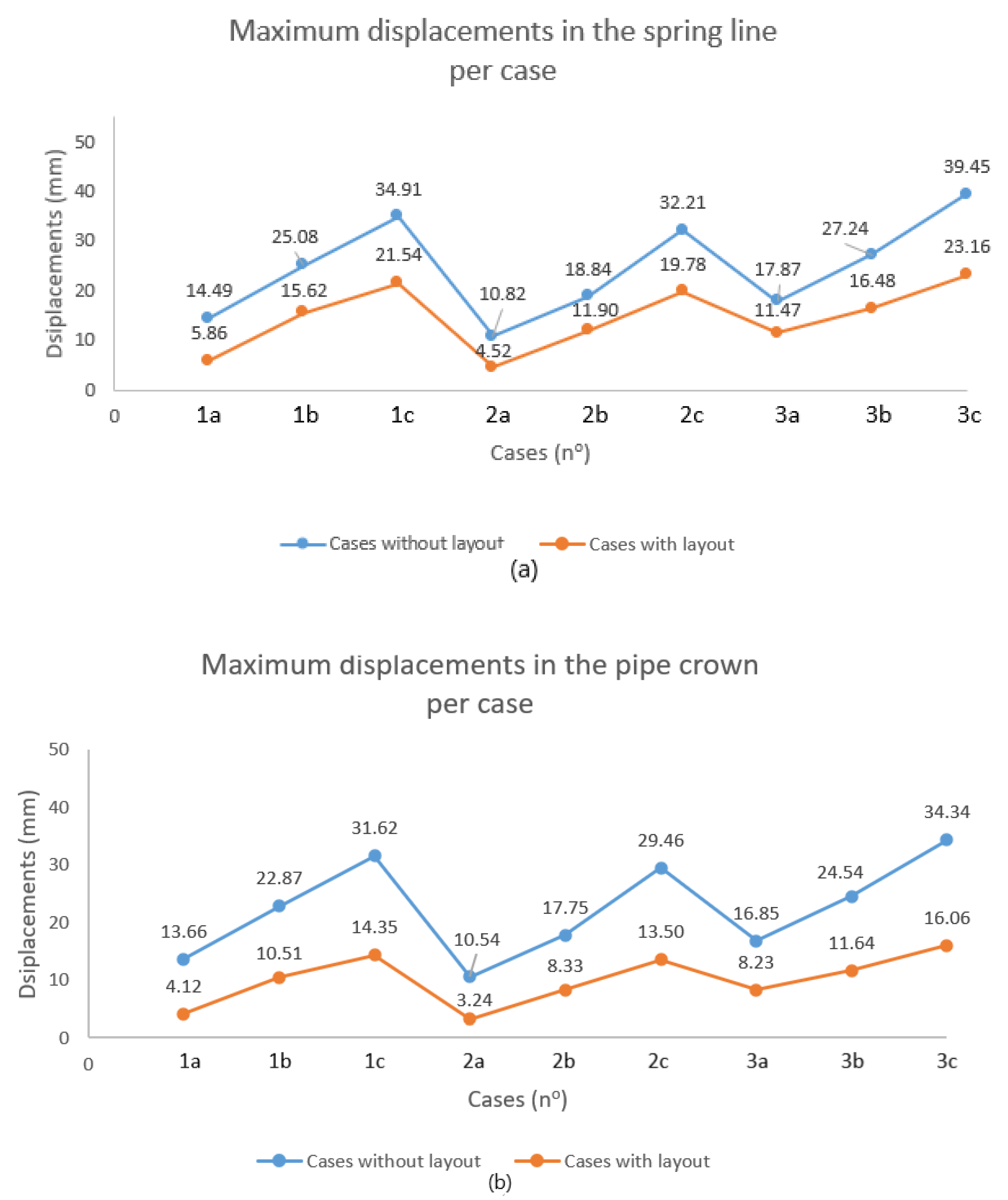
5.3. Maximum Displacements

Figure 9 presents the maximum displacements per case in total for the two reference points selected. The results are extremely satisfying, regarding the mitigation of the blast loadings’ consequences and damages. The reduction ratio varies from 36% to 70% for all the cases, with a median value ranging around 53%. The layout performs more efficiently in the reduction in the pipe crown’s displacements, in contrast with the respective displacements in the spring line.

6. Conclusions

The study presented an efficient meta-material layout for the blast protection of above-ground gas steel pipes. The meta-material layouts’ band-gaps were predicted by adopting the 1D periodic materials theory and were developed within the desirable frequency range of the blast hazards. Proper explosion case scenarios were prepared for the validation of the proposed solution, and the finite element analyses justified the beneficial presence of the meta-material layout. The overall behavior of the pipe with and without the layout proved the substantial mitigation of the blast-induced damages. The reduction in the maximum displacements in the pipe varied from 36% to 70%, demonstrating the efficiency of the meta-material solution towards the under-examination hazard. This study comprises the follow-up of the authors’ previous attempt at testing this type of solution for the similar problem of surface explosions and buried steel pipes. The aim was to develop and present a unique, feasible and common solution for the blast hazards for both above-ground and buried pipelines. This attempt is integrated in the authors’ outer goal to expand the range of civil engineering applications, in which this innovative technology can provide solutions of high effectiveness.

7. Discussion

As it was pointed out also in the introduction, meta-materials have been considered relatively recently as potential solutions for application in civil engineering practice. To this goal, the proposed meta-material concept, after minor changes in its geometrical and material characteristics, can be investigated as an effective solution for the blast protection of other structures (e.g., masonry buildings, gas and electricity plants), including also underground structures (e.g., tunnels and metro stations). Potential changes in the geometrical and material characteristics may be demanded for the pipelines’ protection against explosions of higher magnitude, while a future experimental investigation of the layout’s blast performance is needed in order for the numerical results to be compared and, if so, verified. Moreover, the proposed solution for the protection of gas pipelines can be integrated in a wider resilience assessment framework for EIs, and its contribution to the enhancement of the resilience capacity of EIs can be calculated and quantified.

Author Contributions

Conceptualization, M.K. and C.F.; methodology, M.K. and C.F.; software, M.K.; validation, M.K.; formal analysis, M.K.; investigation, M.K.; writing—original draft preparation, M.K.; writing—review and editing, M.K. and C.F.; visualization, M.K. and C.F.; supervision, C.F.; project administration, C.F. All authors have read and agreed to the published version of the manuscript.

Funding

The current study has been carried out in the scope of the INSPIRE project, which has received funding from the European Union’s Horizon 2020 research and innovation program under the Marie Skłodowska-Curie grant agreement No. 813424.

Data Availability Statement

Not applicable.

Acknowledgments

The authors acknowledge the support of Antoniadis A.I. and Gerolymos Nikolaos, Professor of School of Mechanical Engineering and Assistant Professor of School of Civil Engineering, respectively, at the National Technical University of Athens, for their support in the problem’s conceptualization and design of the proposed solution.

Conflicts of Interest

The authors declare no conflict of interest.

References

  1. Resilience Framework of, U.S. Department of Homeland Security. 2018. Available online: https://www.dhs.gov/sites/default/files/publications/dhs_resilience_framework_july_2018_508.pdf (accessed on 20 April 2023).
  2. Proposal for a Directive of the European Parliament and of the Council on the Resilience of Critical Entities. 2020. Available online: https://eur-lex.europa.eu/legal-content/EN/TXT/?uri=CELEX%3A52020PC0829 (accessed on 20 April 2023).
  3. Directive (EU) 2016/1148 of the European Parliament and of the Council of 6 July 2016 Concerning Measures for a High Common Level of Security of Network and Information Systems across the Union. 2016. Available online: https://eur-lex.europa.eu/eli/dir/2016/1148/oj (accessed on 20 April 2023).
  4. Sun, T.C.; Huang, G.L.; Huang, H.H. On the negative effective mass density in acoustic metamaterials. Int. J. Eng. Sci. 2009, 47, 610–617. [Google Scholar]
  5. Sun, T.C.; Huang, H.H. Wave attenuation mechanism in an acoustic metamaterial with negative effective mass density. New J. Phys. 2009, 11, 013003. [Google Scholar]
  6. US Department of Energy. Development of Seismic Isolation Systems Using Periodic Materials; University of Houston: Houston, TX, USA, 2014. [Google Scholar]
  7. Shi, Z.; Cheng, Z.; Wen-Kai, L. Dispersion Differences and Consistency of Artificial Periodic Structures. IEEE Trans. Ultrason. Ferroelectr. Freq. Control 2017, 64, 1591–1598. [Google Scholar] [CrossRef]
  8. Shi, Z.; Cheng, Z.; Xiang, H. Seismic isolation foundations with effective attenuation zones. Soil Dyn. Earthq. Eng. 2014, 57, 143–151. [Google Scholar] [CrossRef]
  9. Liu, X.; Ren, Y.; Song, X. Combined Attenuation Zones of Combined Layered Periodic Foundations. Appl. Sci. 2021, 11, 7114. [Google Scholar] [CrossRef]
  10. Xiang, H.J.; Shi, Z.F.; Wang, S.J.; Mo, Y.L. Periodic materials-based vibration attenuation in layered foundations: Experimental validation. Smart Mater. Struct. 2012, 21, 112003. [Google Scholar] [CrossRef]
  11. Mo, Y.L.; Shi, Z.; Tang, Y.; Menq, F.; Cheng, Z.; Laskar, A.; Yan, Y. Seismic isolation of two-dimensional periodic foundations. J. Appl. Phys. 2014, 116, 044908. [Google Scholar]
  12. Mo, Y.L.; Shi, Z.; Tang, Y.; Menq, F.; Cheng, Z.; Yan, Y. Three dimensional periodic foundations for base seismic isolation. Smart Mater. Struct. 2015, 24, 075006. [Google Scholar]
  13. Cheng, Z.; Shi, Z.; Palermo, A.; Xiang, H.; Guo, W.; Marzani, A. Seismic vibrations attenuation via damped layered periodic foundations. Eng. Struct. 2020, 211, 110427. [Google Scholar] [CrossRef]
  14. Cheng, Z.; Shi, Z. Composite periodic foundation and its application for seismic isolation. Earthq. Eng. Struct. Dyn. 2018, 47, 925–944. [Google Scholar] [CrossRef]
  15. Cheng, Z.; Shi, Z.; Lin, W. Wave Dispersion Analysis of Multi-story Frame Building Structures Using the Periodic Structure Theory. Soil Dyn. Earthq. Eng. 2018, 106, 215–230. [Google Scholar] [CrossRef]
  16. Jai, S.; Shaik, V.S.A.; Alam, A.; Laskar, A. Application of innovative one-dimensional periodic isolation systems for seismic response reduction of bridges. Adv. Struct. Eng. 2019, 23, 1397–1412. [Google Scholar] [CrossRef]
  17. Agguzzi, G.; Martakis, P.; Dertimanis, K.V.; Colombi, A.; Chatzi, N.E. Nonlinear periodic foundations for seismic protection: Practical design, realistic evaluation, and stability considerations. Soil Dyn. Earthq. Eng. 2021, 150, 106934. [Google Scholar]
  18. Bursi, S.O.; Basone, F.; Wenzel, M.; Fossetti, M. Finite locally resonant Meta-foundations for the seismic protection of fuel storage tanks. Earthq. Eng. Struct. Dyn. 2018, 48, 232–252. [Google Scholar]
  19. Khodakarami, M.I.; Farajian, M.; Sharafi, P. Effect of Meta-Foundation on the Seismic Responses of Liquid Storage Tanks. Appl. Sci. 2022, 12, 2514. [Google Scholar]
  20. Bursi, S.O.; Basone, F.; Wenzel, M. Design of a Metamaterial-Based Foundation for Fuel Storage Tanks and Experimental Evaluation of Its Effect on a Connected Pipeline System. J. Press. Vessel Technol. 2019, 142, 021903. [Google Scholar]
  21. Zhou, P.; Wan, S.; Wang, X.; Fu, J.; Shen, L. Novel periodic pile barriers in saturated soil and applications to propagation attenuation of shear plane waves. Comput. Geotech. 2022, 150, 104925. [Google Scholar] [CrossRef]
  22. Shi, Z.; Cheng, Z.; Wu, J. Numerical Evaluation of the Effectiveness of Periodic Wave Barriers in Pre-stressed Saturated Soil. J. Vib. Eng. Technol. 2022. [Google Scholar] [CrossRef]
  23. Meng, L.; Shi, Z.; Cheng, Z. Vibration mitigation in saturated soil by periodic pile barriers. Comput. Geotech. 2021, 117, 103251. [Google Scholar] [CrossRef]
  24. Meng, L.; Shi, Z.; Cheng, Z. Filtering property of periodic pile barriers under moving loads. Comput. Geotech. 2021, 136, 104244. [Google Scholar] [CrossRef]
  25. Pu, X.; Shi, Z. Periodic pile barriers for Rayleigh wave isolation in a poroelastic half-space. Soil Dyn. Earthq. Eng. 2019, 121, 75–86. [Google Scholar] [CrossRef]
  26. Zhou, J.; Pu, X.; Shi, Z. Attenuation Characteristics of Plane Waves by Metabarriers with Negative Parameters. In Advances in Transportation Geotechnics IV, 1st ed.; Tutumluer, E., Nazaria, S., Al-Qadi, I., Issam, I.A., Eds.; Springer: Cham, Switzerland, 2022; pp. 987–997. [Google Scholar]
  27. Zhou, J.; Cheng, Z.; Shi, Z. Vibration Reduction Performance of a Periodic Layered Slab Track. In Advances in Environmental Vibration and Transportation Geodynamics, 1st ed.; Tutumluer, E., Chen, X., Xiao, Y., Eds.; Springer: Singapore, 2020; pp. 779–791. [Google Scholar] [CrossRef]
  28. Pu, X.; Shi, Z. Broadband surface wave attenuation in periodic trench barriers. J. Sound Vib. 2020, 468, 115130. [Google Scholar] [CrossRef]
  29. Yuan, L.; Cai, Z.; Jiang, H.; Ma, T.; Du, J.; Wang, J. SH wave propagation in a periodic cement-based piezoelectric layered barrier. Mech. Adv. Mater. Struct. 2022, 29, 4902–4910. [Google Scholar] [CrossRef]
  30. Zhang, S.; Wang, W.; Wu, Z.; Dai, Y.; Li, Y.; Zhou, A. Study on Vibration Isolation Effect of Periodic Pile Arrangement on Subway Ground. IOP Conf. Ser. Earth Environ. Sci. 2020, 455, 012152. [Google Scholar] [CrossRef]
  31. Zhou, J.; Gao, Y.; Shi, Z. A Simplified Analytical Method for Detuning Periodic Pile Barriers. J. Appl. Comput. Mech. 2022, 8, 1480–1487. [Google Scholar] [CrossRef]
  32. Liu, C.X.; Yu, G.L. Deep learning-based topology design of periodic barrier for full-mode waves. Constr. Build. Mater. 2022, 314, 125579. [Google Scholar] [CrossRef]
  33. Mitchell, S.J. Metaconcrete: Engineered Aggregates for Enhanced Dynamic Performance. Ph.D. Thesis, California Institute of Technology, Pasadena, CA, USA, 2016. [Google Scholar]
  34. Pandolfi, A.; Ortiz, M.; Bricolla, D. Experimental Validation of Metaconcrete Blast Mitigation Properties. J. Appl. Mech. 2019, 84, 031001. [Google Scholar]
  35. Pandolfi, A.; Ortiz, M.; Bricolla, D.; Cuni, M.; Juli, D.A. Experimental Validation of the Attenuation Properties in the Sonic Range of Metaconcrete Containing Two Types of Resonant Inclusions. Exp. Mech. 2020, 61, 515–532. [Google Scholar]
  36. Kettenbeil, C.; Ravichandran, G. Experimental investigation of the dynamic behavior of metaconcrete. Int. J. Impact Eng. 2018, 11, 199–207. [Google Scholar] [CrossRef]
  37. Liu, Y.; An, X.; Chen, H.; Fan, H. Vibration attenuation of finite-size Metaconcrete: Mechanism, prediction and verification. Compos. Part A Appl. Sci. Manuf. 2021, 143, 106294. [Google Scholar] [CrossRef]
  38. Xu, C.; Hao, H.; Pham, M.T.; Bi, K.; Chen, W. Static mechanical properties and stress wave attenuation of metaconcrete subjected to impulsive loading. Eng. Struct. 2022, 263, 114382. [Google Scholar] [CrossRef]
  39. Hao, H.; Hao, Y.; Jin, H.; Chen, W. Predicting the Response of Locally Resonant Concrete Structure under Blast Load. Constr. Build. Mater. 2020, 252, 118920. [Google Scholar]
  40. Hao, H.; Huang, Z.; Jin, H.; Cheng, X.; Chen, W. Dynamic Response of Metaconcrete Beam Under Blast Load. Int. J. Struct. Stab. Dyn. 2023, 2350178. [Google Scholar] [CrossRef]
  41. Hao, H.; Pham, M.T.; Bi, K.; Cheng, X. Experimental and numerical assessment of stress wave attenuation of metaconcrete rods subjected to impulsive loads. Int. J. Impact Eng. 2022, 159, 104052. [Google Scholar] [CrossRef]
  42. Hao, H.; Cheng, X.; Chen, W. The influence of design parameters of engineered aggregate in Metaconcrete on bandgap region. J. Mech. Phys. Solids 2022, 139, 103929. [Google Scholar]
  43. Hao, H.; Jin, H.; Chen, W.; Cheng, X. Effect of enhanced coating layer on the bandgap characteristics and response of metaconcrete. Mech. Adv. Mater. Struct. 2023, 30, 175–188. [Google Scholar] [CrossRef]
  44. Zhang, E.; Zhao, H.; Iu, G.; Chen, P.; Yang, H. Design and evaluation of dual-resonant aggregates metaconcrete. Lat. Am. J. Solids Struct. 2023, 20, e479. [Google Scholar] [CrossRef]
  45. Tran, P.; Nguyen-Van, V.; Peng, C.; Hazell, P.J.; Lee, L.; Nguyen-Xuan, H. Performance of meta concrete panels subjected to explosive load: Numerical investigations. Struct. Concr. 2023. [Google Scholar] [CrossRef]
  46. Tarlochan, F. Sandwich Structures for Energy Absorption Applications. Materials 2021, 14, 4731. [Google Scholar] [CrossRef]
  47. Ngo, T.; Bohara, P.R.; Linforth, S.; Nguyen, T.; Ghazlan, A. Dual-mechanism auxetic-core protective sandwich structure under blast loading. Compos. Struct. 2022, 299, 116088. [Google Scholar] [CrossRef]
  48. Li, Z.; Chen, W.; Hao, H. Blast mitigation performance of cladding using Square Dome-shape Kirigami folded structure as core. Int. J. Mech. Sci. 2018, 145, 83–95. [Google Scholar] [CrossRef]
  49. Vo, N.; Hao, H.; Pham, M.T.; Bi, K.; Chen, W. Impact Load Mitigation of Meta-panels with Single Local Resonator. Eng. Struct. 2022, 265, 114528. [Google Scholar] [CrossRef]
  50. Hao, H.; Vo, N.; Bi, K.; Pham, T.; Chen, W. Stress Wave Mitigation Properties of Dual meta-Panels against Blast Loads. Int. J. Impact Eng. 2021, 154, 103877. [Google Scholar]
  51. Hao, H.; Vo, H.N.; Bi, K.; Pham, M.T.; Chen, W.; Bi, K.; Ha, N.S. Blast resistant enhancement of meta-panels using multiple types of resonators. Int. J. Mech. Sci. 2022, 215, 106965. [Google Scholar]
  52. Fan, H.; He, H. Dynamic theory of sandwich meta-panel under blast load. Eur. J. Mech./Solids 2022, 94, 104599. [Google Scholar]
  53. Vo, N.; Pham, M.T.; Hao, H.; Bi, K.; Chen, W. Experimental and Numerical Validation of Impact Mitigation Capability of Meta-panels. Int. J. Mech. Sci. 2022, 231, 107591. [Google Scholar] [CrossRef]
  54. Fan, H.; He, H. Explosion vibration mitigation of meta-plate with mass–spring metastructures. Extrem. Mech. Lett. 2021, 42, 101108. [Google Scholar]
  55. Li, Q.Q.; He, C.H.; Li, E.; Liu, P.; Lin, Y.X.; Wu, Y. Design of resonant structures in resin matrix to mitigate the blast wave with a very wide frequency range. Smart Mater. Struct. 2020, 29, 045042. [Google Scholar] [CrossRef]
  56. Huang, G.; Xu, X.; Gang, X.; Yangyang, C.; Wen, J.; Barnhart, V.M. A nonlinear dissipative elastic metamaterial for broadband wave mitigation. Int. J. Mech. Sci. 2019, 164, 105159. [Google Scholar]
  57. Huang, G.; Chen, H.; Chen, Y.Y.; Barnhart, V.M. Elastic Metamaterials for Blast Wave Impact Mitigation. In Blast Mitigation Strategies in Marine Composite and Sandwich Structures, 1st ed.; Rajapakse, Y., Gopalakrishnan, S., Eds.; Springer: Singapore, 2018; pp. 357–375. [Google Scholar] [CrossRef]
  58. Tan, T.K.; Huang, H.H.; Sun, T.C. Blast-wave impact mitigation using negative effective mass density concept of elastic metamaterials. Int. J. Impact Eng. 2014, 64, 20–29. [Google Scholar] [CrossRef]
  59. Yang, J.; Kim, E.; Hwang, Y.H.; Shul, W.C. Impact and blast mitigation using locally resonant woodpile metamaterials. Int. J. Impact Eng. 2017, 101, 24–31. [Google Scholar]
  60. Kontogeorgos, M.; Fuggini, C. Meta-Material Layout for the Protection of Buried Steel Pipes against Surface Explosion. Geotechnics 2022, 2, 427–440. [Google Scholar] [CrossRef]
  61. Hernández-Báez, A.; Torres, E.S.; Amaya-Gomez, R.; Pradilla, D. Oil Onshore Pipeline Quantitative Risk Assessment under Fire and Explosion Scenarios. Processes 2023, 11, 557. [Google Scholar] [CrossRef]
  62. Cheng, L.; Ma, L.; Li, M. Quantitative risk analysis of urban natural gas pipeline networks using geographical information systems. J. Loss Prev. Process Ind. 2013, 26, 1183–1192. [Google Scholar]
  63. Pourtaghi, G.; Kouhpaee, H.; Esmaeili, R.; Gholamnia, R.; Jabbari, M. Risk assessment of fire, explosion and release of toxic gas of Siri–Assalouyeh sour gas pipeline using fuzzy analytical hierarchy process. Heliyon 2021, 7, e07835. [Google Scholar]
  64. Piccinelli, R.; Krausmann, E. Analysis of natech risk for pipelines: A review. In Joint Research Centre Scientific and Policy Reports; Publications Office of the European Union: Luxembourg, 2013. [Google Scholar]
  65. Girgin, S.; Krausmann, E. Historical analysis of U.S. onshore hazardous liquid pipeline accidents triggered by natural hazards. J. Loss Prev. Process Ind. 2016, 40, 578–590. [Google Scholar] [CrossRef]
  66. Hao, H.; Zhang, X. Challenges of Effective Blast Protection of Buildings. In Engineering for Extremes, 1st ed.; Rosowsky, D.V., Stewart, G.M., Eds.; Springer: Cham, Switzerland, 2021; pp. 93–117. [Google Scholar] [CrossRef]
  67. Hao, H.; Hao, Y.; Jin, H.; Chen, W. Review of the current practices in blast-resistant analysis and design of concrete structures. Adv. Struct. Eng. 2016, 19, 1193–1223. [Google Scholar] [CrossRef]
  68. Unified Facilities Criteria. Structures to Resist the Effects of Accidental Explosions, 1st ed.; U.S. Army Corps of Engineers, Naval Facilities Engineering Command, Air Force Civil Engineer Support Agency: Washington, DC, USA, 2008. [Google Scholar]
  69. Oliveira, V.D.; Rana, S.; Fangueiro, R.; Pichandi, S. Fibrous and composite materials for blast protection of structural elements-A state-of-the-art review. J. Reinf. Plast. Compos. 2014, 32, 1477–1500. [Google Scholar] [CrossRef]
  70. Salih, Y.A.; Abdulla, A.I.; Jomaa’h, M.M. Impact Resistance of GFRP Reinforced Concrete One-Way Slabs. Inf. Sci. Lett. 2022, 11, 1267–1275. [Google Scholar]
  71. Xie, Z.; Duan, Z.; Guo, Y.; Li, X.; Zen, J. Behavior of Fiber-Reinforced Polymer-Confined High-Strength Concrete under Split-Hopkinson Pressure Bar (SHPB) Impact Compression. Appl. Sci. 2019, 9, 2830. [Google Scholar] [CrossRef] [Green Version]
  72. Adhikary, S.D.; Goswami, A. Retrofitting materials for enhanced blast performance of Structures: Recent advancement and challenges ahead. Constr. Build. Mater. 2019, 204, 224–243. [Google Scholar]
  73. Kovacs, T.; Nyikes, Z.; Figuli, L. Application of High Energy Absorbing Materials for Blast Protection. Acta Mater. Transylvanica 2018, 1, 93–96. [Google Scholar] [CrossRef]
  74. Ha, S.N.; Marundrury, S.S.; Pham, T.; Pournasiri, E.; Shi, F.; Hao, H. Effect of grounded blast furnace slag and rice husk ash on performance of ultra-high-performance concrete (UHPC) subjected to impact loading. Constr. Build. Mater. 2022, 329, 127213. [Google Scholar] [CrossRef]
  75. Wei, J.; Li, J.; Wu, C.; Liu, Z.X.; Fang, J. Impact resistance of ultra-high-performance concrete strengthened reinforced concrete beams. Int. J. Impact Eng. 2021, 158, 104023. [Google Scholar] [CrossRef]
  76. Zeng, J.; Long, T. Compressive Behavior of FRP Grid-Reinforced UHPC Tubular Columns. Polymers 2022, 14, 125. [Google Scholar] [CrossRef]
  77. Mohammadi, Y.; Sadeghian, A.; Shaghaghi, T.M.; Taghipoor, H. Performance Assessment of Hybrid Fibre-Reinforced Concrete (FRC) under Low-Speed Impact: Experimental Analysis and Optimized Mixture. Shock Vib. 2023, 2023, 7110987. [Google Scholar] [CrossRef]
  78. Si, Z.; Liu, F.; Pan, J.; Dong, H. Research on Impact Resistance of Reinforced Concrete Beams Strengthened with Carbon Fiber Reinforced Polymer Grid and Engineered Cementitious Composites. Polymers 2022, 14, 1951. [Google Scholar] [CrossRef]
  79. Do, V.T.; Pham, T.; Gehl, A.; Hao, H.; Nguyen, T.P. Impact Responses of Precast Hollow Reinforced Concrete Beams with Prestress Tendons using High-Fidelity Physics-Based Simulations. Eng. Fail. Anal. 2021, 131, 729–742. [Google Scholar] [CrossRef]
  80. Yan, X.; Lin, C.; Liu, X.; Zheng, T.; Shi, S.; Mao, H. Numerical and Analytical Investigations of the Impact Resistance of Partially Precast Concrete Beams Strengthened with Bonded Steel Plates. Buildings 2023, 13, 696. [Google Scholar] [CrossRef]
  81. Mao, H.; Yan, X.; Zong, C.; Lin, C. Numerical Analysis of the Impact Resistance of Partially Precast Concrete Beams and Prediction of the Displacement Response. KSCE J. Civ. Eng. 2023, 27, 2058–2072. [Google Scholar] [CrossRef]
  82. Xue, S.; Hao, H.; Hao, Y. Numerical evaluation of the impact performance of precast concrete segmental columns and strengthening techniques. Eng. Struct. 2021, 244, 112725. [Google Scholar] [CrossRef]
  83. Huang, Z.; Chen, W.; Tran, T.T.; Pham, T.; Hao, H.; Chen, Z.; Elchalakani, M. Experimental and Numerical Study on Concrete Beams Reinforced with Basalt FRP Bars under Static and Impact Loads. Compos. Struct. 2021, 263, e386–e395. [Google Scholar] [CrossRef]
  84. Zhang, X.; Hao, H.; Li, C.; Do, V.T. Experimental study on the behavior of precast segmental column with domed shear key and unbonded post-Tensioning tendon under impact loading. Eng. Struct. 2018, 173, 589–605. [Google Scholar] [CrossRef]
  85. Mao, H.; Yan, X.; Zong, C.; Lin, C.; Liu, X. Experimental Research on Impact Resistance of Partially Precast Concrete Beams. KSCE J. Civ. Eng. 2023, 26, 4038–4051. [Google Scholar] [CrossRef]
  86. Kheyroddin, A.; Arshadi, H.; Ahadi, M.R.; Taban, G.; Kioumarsi, M. The impact resistance of Fiber-Reinforced concrete with polypropylene fibers and GFRP wrapping. Mater. Proc. 2021, 45, 5433–5438. [Google Scholar] [CrossRef]
  87. Wang, W.; Mo, Z.; Chouw, N.; Xu, Z.D. Impact resistance of flax FRP fully wrapped coconut fibre reinforced concrete beams and shear contribution of FRP. Constr. Build. Mater. 2023, 392, 131922. [Google Scholar] [CrossRef]
  88. Zhang, X.; Hao, H. Improved Impact Resistant Capacity of Segmental Column with Fibre Reinforced Polymer Wrap. Int. J. Impact Eng. 2018, 125, 117–133. [Google Scholar] [CrossRef]
  89. Quek, J.; Liu, C.; Musngi, J.V.; Malalasekara, P.B. A comparison of finite element simulation and experimental results from reinforced concrete columns wrapped with fibre-reinforced polymer subjected to blast loading. Int. J. Comput. Methods Exp. Meas. 2020, 8, 233–242. [Google Scholar] [CrossRef]
  90. Olarewaju, J.; Kameswara Rao, N.S.V.; Mannan, M.A. Blast Effects on Underground Pipes. Electron. J. Geotech. Eng. 2010, 15, 645–658. [Google Scholar]
  91. Ngo, T.; Mendis, P.; Gupta, A.; Ramsay, J. Blast loading and blast effects on structures—Overview. EJSE Spec. Issue: Load. Struct. 2007, 1, 76–91. [Google Scholar] [CrossRef]
  92. Shirbhate, P.A.; Goel, M.D. A Critical Review of Blast Wave Parameters and Approaches for Blast Load Mitigation. Arch. Comput. Methods Eng. 2020, 28, 1713–1730. [Google Scholar] [CrossRef]
  93. Department of Defense. Unified Facilities Criteria: Structures to Resist the Effects of Accidental Explosions; UFC 3-340-02; Department of Defense: Washington, DC, USA, 2008. [Google Scholar]
  94. Solomos, G.; Karlos, V. JRC Technical Reports: Calculation of Blast Loads for Application to Structural Components, 1st ed.; Publications Office of the European Union: Luxembourg, 2008. [Google Scholar]
  95. Anirban, D.; Zimmie, Τ. Effects of Surface Explosion on Underground Tunnel and Potential Mitigation Measures. Transp. Infrastruct. Geotechnol. 2016, 3, 74–90. [Google Scholar]
  96. US Nuclear Regulatory Commission. Characterizing Explosive Effects on Underground Structures; Office of Nuclear Security and Incident Response: San Antonio, TX, USA, 2014. [Google Scholar]
  97. Ibrahim, E.Y.; Nabil, M. Finite Element Analysis of Pile Foundations Under Surface Blast Loads. In Proceedings of the 13th International Conference on Damage Assessment of Structures, Porto, Portugal, 9–10 July 2019; Wahab, M.A., Ed.; Springer Nature: Singapore, 2020; pp. 446–460. [Google Scholar]
Figure 1. The adopted analytical model for the form of the pressure loading on pipe due to free-air explosion.
Geotechnics 03 00032 g001
Figure 2. A typical blast loading profile.
Geotechnics 03 00032 g002
Figure 3. Schematic representation of the configuration of the periodic materials theory’s (a) conceptual structure and (b) unit cell [60], where indexes 1, 2 indicate layers A, B, respectively; ρ1, ρ2, are expressing the densities of the chosen materials, λ1, λ2; and μ1, μ2 denote the Lamé’s constants of each layer.
Geotechnics 03 00032 g003
Figure 4. The meta-material layout’s (a) 3D shape and (b) cross section. The layout consists of 8 layers (of 5.00 cm thickness each), where the green layers refer to the polyurethane foam and the gray ones to rubber. The red layer refers to the steel pipe (of 1.50 cm thickness).
Geotechnics 03 00032 g004
Figure 5. Schematic presentation of the meta-material layout’s band-gaps.
Geotechnics 03 00032 g005
Figure 6. Three-dimensional finite element representation of the problem, depicting the mesh of each model and the location of the blast sources, (a) for the cases without the presence of the meta-material layout and (b) with the layout. XYZ refers to the rectangular co-ordinate system.
Geotechnics 03 00032 g006
Figure 7. Overall presentation of the displacements in the pipe spring line, with and without the presence of the layout for each explosion scenario. The reduction in the displacements within the whole phase of the blast loadings, in each explosion scenario case, depicts the beneficial results of the layout.
Geotechnics 03 00032 g007
Figure 8. Overall presentation of the displacements in the pipe crown, with and without the presence of the layout for each explosion scenario. The reduction in the displacements within the whole phase of the blast loadings, in each explosion scenario case, proves the beneficial results of the layout.
Geotechnics 03 00032 g008
Figure 9. Overall presentation of the maximum displacements for every case in (a) the pipe’s spring line and (b) the pipe’s crown.
Geotechnics 03 00032 g009
Table 1. Properties of the selected materials, consisting of the meta-material layout.
PropertiesMaterial 1
Polyurethane Foam
Material 2
Rubber
Density ρ (kg/m3)9001300
Young’s Modulus E (Pa)1.47 × 10858,000
Poisson’s ration ν0.420.463
Table 2. The meta-material layout’s band-gaps for the frequencies until 750 Hz.
Attenuation Zone No.Frequency Range (Hz)
124.27–39.03
253.69–78.06
387.74–117.10
4124.13–156.13
5161.61–195.17
6199.64–234.20
7237.98–273.23
8276.52–312.27
9315.17–351.30
10353.91–390.33
11392.70–429.37
12431.54–468.40
13470.42–507.43
14509.32–546.46
15548.24–585.49
16587.17–624.52
17626.12–663.55
18665.08–702.58
19704.05–741.61
Table 3. The explosion case scenarios considered, with and without the meta-material layout.
Case No.SubcaseTNT
Charge (kg)
Distance from
Pipe (m)
Z
(m/kg 0.333)
ttot =
tA + to (ms)
1a502.500.684.79
b1002.500.542.18
c1502.500.472.23
2a503.500.958.44
b1003.500.757.57
c2003.500.604.09
3a1505.000.9410.33
b2505.000.799.76
c4005.000.688.84
Disclaimer/Publisher’s Note: The statements, opinions and data contained in all publications are solely those of the individual author(s) and contributor(s) and not of MDPI and/or the editor(s). MDPI and/or the editor(s) disclaim responsibility for any injury to people or property resulting from any ideas, methods, instructions or products referred to in the content.

