Review

In-Process Monitoring of Temperature Evolution during Fused Filament Fabrication: A Journey from Numerical to Experimental Approaches

by
Hamid Reza Vanaei
1,2,*,
Mohammadali Shirinbayan
2,
Michael Deligant
1,
Sofiane Khelladi
1 and
Abbas Tcharkhtchi
2
1
Arts et Métiers Institute of Technology, CNAM, LIFSE, HESAM University, 75013 Paris, France
2
Arts et Métiers Institute of Technology, CNRS, CNAM, PIMM, HESAM University, 75013 Paris, France
*
Author to whom correspondence should be addressed.
Thermo 2021, 1(3), 332-360; https://doi.org/10.3390/thermo1030021
Submission received: 8 September 2021 / Revised: 18 October 2021 / Accepted: 22 October 2021 / Published: 27 October 2021

Abstract

:
Fused filament fabrication (FFF), an additive manufacturing technique, unlocks alternative possibilities for the production of complex geometries. In this process, the layer-by-layer deposition mechanism and several heat sources make it a thermally driven process. As heat transfer plays a particular role and determines the temperature history of the merging filaments, the in-process monitoring of the temperature profile guarantees the optimization purposes and thus the improvement of interlayer adhesion. In this review, we document the role of heat transfer in bond formation. In addition, efforts have been carried out to evaluate the correlation of FFF parameters and heat transfer and their effect on part quality. The main objective of this review paper is to provide a comprehensive study on the in-process monitoring of the filament’s temperature profile by presenting and contributing a comparison through the literature.

1. Introduction

Additive manufacturing (AM) is a process of joining, layer-by-layer, a 3D object from 3D models developed in the 80s of the 20th century [1]. Due to the significant advances in the development of this process, such as the reduction in time/cost and the possibility of creating complex geometries, it has attracted a lot of attention in the last decades [2,3,4] through different applications (e.g., aerospace, automotive, biomedical, etc.) [5,6,7,8]. These characteristics, incorporated with AM technologies to fabricate complex geometries in the micrometer order, have made this technology an advanced industry [9].
To date, several techniques have been developed in AM. They are based on the 3D printing (layer-by-layer) mechanism or other techniques, such as stereolithography (SL), selective laser sintering (SLS), laminated object manufacturing (LOM), fused filament fabrication (FFF), etc. [10].
SLS is a powder-based process through which, by the laser scanning of a power-bed, a 3D structure is formed layer-by-layer [11]. LOM, first developed in 1991, is where a laser cuts 2D cross-sections to laminate the sheets using metals, plastics, and paper [12]. SL, patented in 1986 by Charles Hill, is a 3D printing technique forming polymers layer-by-layer using a photochemical process by means of lights [13].
Regarding different methods that are widely used in AM, FFF has brought much attention due to its ability to provide functional prototypes in numerous polymers [14] and thermoplastics [15] (e.g., acrylonitrile butadiene styrene (ABS), polycarbonate (PC), polylactic acid (PLA), polyethylene terephthalate glycol (PETG), Nylon, etc.) and composite-based polymers [16,17]. FFF, also known as fused deposition modeling (patented in 1989 [18]), was developed and utilized for modeling and prototyping to produce complex geometrical, low cost, and easy operation parts. Despite the mentioned advantages of FFF, the quality of the final parts is still a missing point [19,20,21].
One of the most important features in FFF is that the bonding location is the point of failure. During the material deposition, a hot layer is deposited on/beside the previous layer(s) that are already under the cooling stage. This issue causes the cooling and re-heating of filaments, resulting in a small-time gap where the polymer–polymer interfaces are above the glass transition temperature (Tg for amorphous materials) or crystallization temperature (Tc for semi-crystalline materials). On the other hand, the adhesion of layers for the FFF parts is thermally driven. Their temperature history should be considered as a critical variable in characterizing the mechanical characteristics of the final parts [22,23,24,25].
Although (FFF)-3D printing has attracted significant attention in recent years, several review papers on the 3D printing of polymeric (or even composite) materials have focused on critical characteristics and challenges, such as the mechanical properties of fabricated parts, application of various materials, and the process design [13,26,27,28,29]. Based on the existence of review papers that consider the different aspects of the FFF, such as heat transfer [30], further review on the in-process monitoring of the temperature profile during FFF is still missing. This paper contributes to persuading readers of its noteworthy aspect of heat transfer and its remarkable impact on the bonding/strength of 3D-printed parts. Research studies that consider the heat transfer are discussed both experimentally and numerically. In addition, a comparison representing the advantages and limitations of each approach is also singled out.
The paper is organized as follows: Section 2 and Section 3 explain the engagement of FFF parameters and, consequently, the role of heat transfer in the quality of the final parts. Section 4 presents the importance of the temperature profile investigation, as well as the in-process monitoring at the interface of the deposited layers. Finally, we conclude on the overall work.

2. FFF Parameters and Their Impact on Part Quality

An overview of the research expressed that a large number of studies have been carried out on RP/AM techniques (e.g., SLA, LOM, SLS). However, the possibility of improvement in FFF has not been suitably addressed. In general, it has been found that FFF acts as a slower process due to the existence of a layer-by-layer mechanism [31]. The construction of FFF parts is based on the mentioned mechanism in order to produce the desired geometry, such as cubes. However, for some complex geometry, it is not possible to achieve accurate dimensions. A work carried out by Chennakesava et al. [11] has shown the part orientation to be considered as the main parameter on the dimensional accuracy of the 3D-printed parts. They have concluded that the lower the degree of orientations, the higher the accuracy, and thus the lower the angle for layer deposition. Several studies have focused on improving the dimensional accuracy of 3D-printed parts [32,33,34]. However, in order to increase the application of the FFF process, the strength and mechanical performances of the final parts need to be focused on. In addition, the impact of temperature change on surface roughness has been taken into account [35,36]. It was found that, by increasing the temperature, there was a decrease in surface roughness.
The mechanical behavior of FFF parts is usually lower than the parts fabricated by traditional manufacturing processes. Although the main drawback is due to the principle involved in the production stage, the wrong choice of the process parameters was found to be more essential. As stated by Chennakesava et al. [11], the selection of process parameters acts as an important action in part fabrication. As the role of FFF parameters determines the build cost and time, developers and designers must understand the influence of process parameters to improve the quality of the final components [37].
Furthermore, as each material acts regarding its characteristic, it is necessary to provide an interaction of parameters, as well as the material characteristic. In what follows, a review of the literature has been performed to realize the studies that have been carried out in this direction.
As an important indicator, they proposed to take into account the mechanical performance of the fabricated parts during the AM/RP manufacturing process. More precisely, in FFF machines, the process parameters have a considerable impact on the mechanical performance of the final part during the manufacturing process. An unsuitable choice of the process parameters could be the main reason for their poor mechanical characteristics. Controlling and optimizing the process parameters on the part quality, which is the strength of the FFF parts, could be improved, and, thus, it is essential to understand their importance [37].
Górski et al. [38] explored the influence of part orientation by implementing bending and tensile tests on the parts that have been produced in distinct orientations. It changed the strength of the ABS specimens. Their results indicated that this parameter has a substantial effect on their tensile and bending behavior. In another work, Lee et al. [39] investigated the impact of build orientation on the compressive behavior of fabricated parts, and found a higher compressive strength for the transversely printed specimens in comparison with that of axial specimens. In another similar work, the effect of this parameter was explored by taking into consideration the flexural and tensile strength of ABS specimens [40]. It was found that the axial layer deposition has higher inter-layer bonding. Smith et al. [41] investigated the influence of the build orientation on the mechanical behavior of 3D-printed polycarbonate, and concluded that the ultimate strength of the materials is highly affected by the variation of this parameter. In another work, Schöppner et al. [42] studied the influence of build direction, and its impact on the mechanical properties of 3D-printed polyetherimide (PEI) parts. Using the compressive test, a higher modulus was obtained for the samples fabricated in the horizontal direction.
Another parameter that has an impact on the mechanical behavior and quality of the final parts is layer thickness. Several works have noted the influence of this parameter on the mechanical properties of the 3D-printed parts. Ahn et al. [31] evaluated the effect of the layer thickness of ABS, and found that there is no significant change in the mechanical properties of the fabricated parts, whereas another work on PLA showed that the increase in layer thickness results in a higher strength of the 3D-printed parts. Approximately, in research on PLA and ABS, attempts have been made to consider the effect of layer thickness by investigating the variation of mechanical properties. However, researchers have widely focused on other thermoplastic polymers, such as PEEK. El Magri et al. [43] investigated the influence of layer thickness on the mechanical and thermal properties of 3D-printed PEEK, in both as-produced and annealed parts. They found that the layer thickness has a considerable impact; however, without any specific order. Another interesting work by Wang et al. [44] compared the effect of layer thickness as a function of the liquefier diameter. They stated that the lower layer thickness (d = 0.1 mm) can strengthen the bonding between layers.
The layer angle between deposited filaments also acts as an essential parameter in determining the mechanical properties of the printed parts. Several works studied how the layer angle affects the mechanical properties of the fabricated parts [45,46,47,48]. They have all reported that the mechanical characteristics changed according to the variation of this parameter.
Although the concentration of the explained studies is mostly on the individual involvement of FFF parameters, limited works have focused on the interaction between them. Masood et al. [49] analyzed the influence of the air gap, raster width, and raster angle on the tensile behavior of 3D-printed polycarbonate. In another similar work, Motaparti et al. [50] analyzed the influence of the air gap and raster angle on the compressive behavior of an ULTEM 9085 specimen. They found that the interaction of the raster angle and build direction affected its compressive strength.
More broadly, Khan et al. [51] used Taguchi analysis to discover the ideal collection of process parameters, such as the layer thickness and air gap, that affect the elastic performance of ABS prototypes. The influence of the raster angle on the resulting residual stress has also been studied [52]. They found that a raster angle of ±30 had the higher residual stress.
Process parameters also impact the build time and cost of the 3D-printed parts. Rathee et al. [53] studied the influence of spatial orientation on the time required for fabrication purposes. They used response surface methodology (RSM) to propose the experimental procedures. Orientations had a significant effect on the build time, as reported by authors. In summary, a detailed investigation of several studies shows the following limitations:
  • An overview performed on the influence of process parameters through the part quality fabricated by the FFF process appears to have conflict in their obtained results. For example, a study in 2002 concluded that the layer thickness has a less significant influence on the tensile strength. After 3 years, other researchers found that the tensile strength of an FFF part first decreased and then increased as the layer thickness increased. A few years later, in 2010, another research proposed that the layer thickness has a low impact on the tensile strength. These consequences call for a comprehensive investigation through the FFF parameters;
  • FFF parameters not only affect the part quality but also greatly influence the build time involved. However, studies on the influence of process parameters on the build time were found to be in the development stage;
  • Almost all research has focused on investigating one material at a time, or even one parameter. In contrast, there are a number of parameters in reality that play an essential role during production. Furthermore, based on the various research in literature, investigating the simultaneous effect of important parameters is required in order to better understand the FFF parameters;
  • A thorough investigation of the combined effect of FFF parameters is required, which helps in further understanding the influence of each parameter with their interaction on the bond quality. This point of view helps to optimize the FFF process in order to reach the final goal, which is the improvement of bond quality.
As discussed, the quality of a final object fabricated by the FFF process mainly relies on applied parameters. The main issues and areas of concern of any FFF user concerning the quality are the build time and build cost. There are much lower mechanical properties of parts fabricated by FFF, compared to traditional manufacturing processes, where several parameters affect the final parts. It is important to consider the main parameters and their impact on the final part in order to improve the part quality.

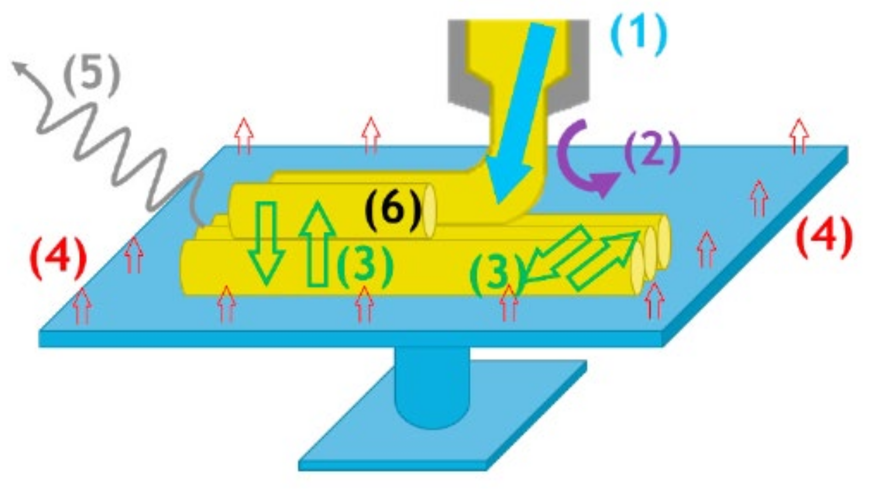
3. Role of Heat Transfer in FFF

In the FFF process, a thermoplastic polymer is fed into a liquefier that extrudes a filament while moving in successive X-Y planes along the Z direction to fabricate a 3D part in a layer-by-layer process. Consequently, as the deposition progresses, the hot filament is deposited onto the previously deposited filaments, and are consequently in the process of cooling. This causes their re-heating, defining a time when the interfaces of contacting filaments are above the glass transition temperature (Tg) in the case of amorphous materials or the crystallization temperature (Tc) for semi-crystalline materials, which is necessary for proper bonding to take place. Therefore, each filament should be sufficiently hot during deposition, but not too hot, to avert deformation due to the gravity and the weight of the filaments deposited in subsequent layers. This issue could be illustrated schematically, as shown in Figure 1. There are several heat transfer mechanisms during FFF, as shown below [54,55]:
(1)
Heat induced by the liquefier;
(2)
Convective cooling of the filaments with the air: the effect of heat transfer coefficient (hconv) is inevitable [54];
(3)
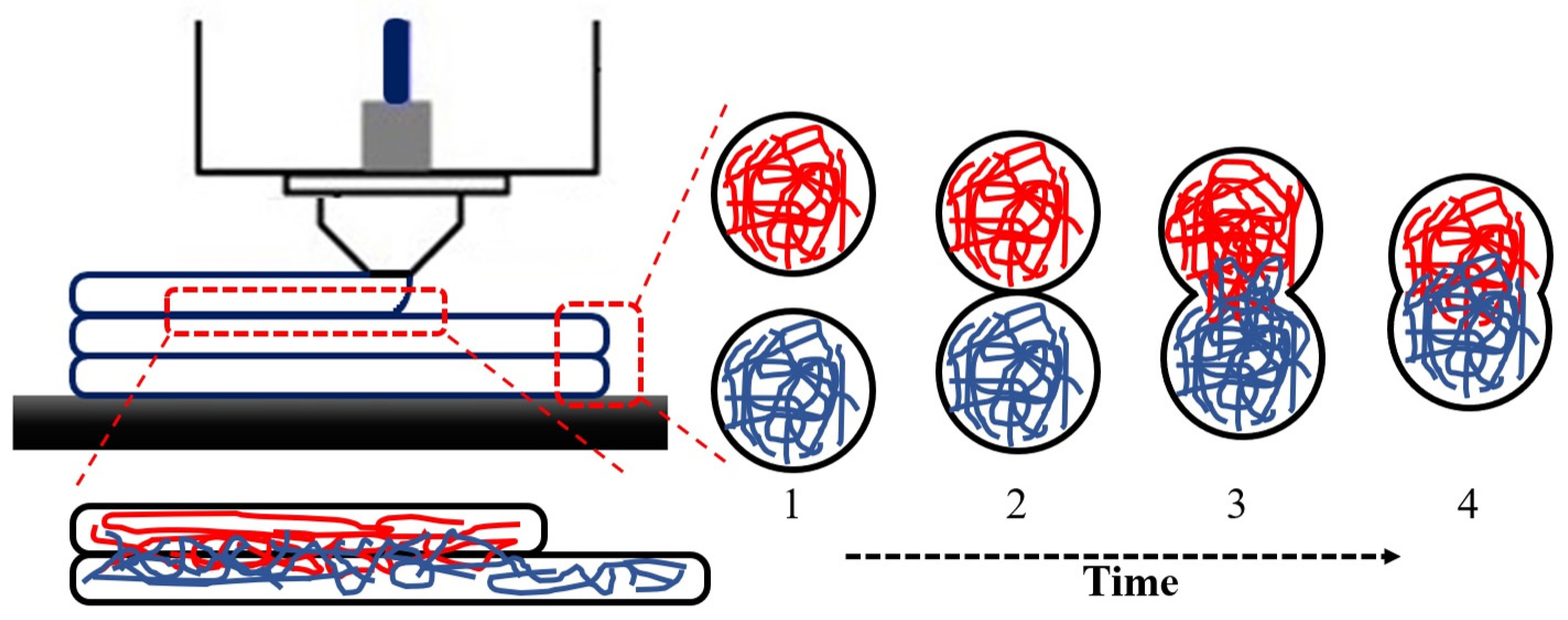
Heat exchanges between the adjacent filaments: the conductance and deposition sequences control the interaction intensity;
(4)
Heat brought by the support plate: this is defined as the conduction controlled by the thermal contact conductance and contact area;
(5)
Radiative losses: This consists of radiation between the filament and surroundings and radiation between adjacent filaments;
(6)
Heat source from the exothermal crystallization for semi-crystalline polymers.
Several types of research were performed on the thermal history prediction of filaments while deposited. Bellehumeur et al. [55] proposed the lumped capacity model by assuming a uniform temperature profile of the filament’s cross-section. Their 2D analysis was simplified to a 1D transient heat transfer model for the cooling process of deposited layers. Despite the simplification proposed in this approach, the simulation does not contribute to the complex geometries. Considering the contacts between filaments, Costa et al. [57] suggested an analytical solution for the transient heat transfer during the deposition of filaments. Although they have neglected the axial and radial heat conductions, they have recently distinguished the contribution of various thermal phenomena engaged in the process [58]. The main disadvantage of their approaches is the limitation of experimental validations and the distance between the obtained results and reality. Thomas and Rodriguez [59] have also presented a 2D thermal model in a specific deposition shape. In this work, the conduction and any contact resistance of the filaments have been neglected. Moreover, Yardimici et al. [60,61] proposed a 1D thermal model in their works by taking into account the thermal interaction with the environment and between the deposited filaments. Zhang et al. [62] developed a FEM, applying element activation, to simulate thermomechanical characterization in FFF. A 3D transient thermal FEM developed by Ji et al. [63] considers the thermal conduction and heat capacity. The weakness of all analytic approaches is that simplified closed-form solutions are limited to simple geometry and cannot be applied to realistic parts and manufacturing processes.
After a decade, and by the expiration of the Stratasys FDMTM [64] in 2010, many works on 3D printing have progressively been raised. The main reason relies on the emersion of open-source 3D printers and, thus, the possibility of working on different aspects of optimization purposes. Peng et al. [65] used a temperature sensor to study the temperature variation during the extrusion process. They found that, by raising the print speed, there is a deviation from the isothermal flow. Considering the experimental validation that they implemented for their approach, the extrusion process during the filament deposition acts as a non-isothermal process. Therefore, temperature variation plays an important role and should be controlled for optimization purposes.
Similarly, another work considered an experimental set-up to investigate the relationship between the input filament speed and feeding force at different liquefier temperatures [66]. They found that the liquefier temperature acts as a limitation criterion. In addition, Vaes et al. [67] applied an IR sensor to investigate the temperature variation parallel to the filament deposition. Cattenone et al. [68] predicted the distortion of 3D-printed parts using a finite element analysis. By implementing an experimental validation to the obtained results, the authors show that the mechanical properties of 3D-printed parts are highly affected by the local temperature distribution.
In addition, Seppala and Migler [69] used an IR camera to study the temperature distribution around the active printing area. In another similar work, D’Amico and Peterson [70] applied a finite element analysis to simulate the heat transfer during the FFF process. In both works, using an IR camera, they contributed a temperature profile of the external surface of the printed objects. Thus, the simulations were validated based on the mentioned results.
More recently, Costa et al. developed a heat transfer model that included the transient heat conduction between the filament and/or the built platform [57,71]. They found that the temperature profile of filaments is highly affected by the physical contact between the filaments. Accordingly, they considered the involved parameters during their experimental validation. However, the results obtained by implementing an IR camera show that the contacts between filaments play a crucial role and should be considered in heat transfer investigations.
In the section that follows, a discussion on the influence of the most critical process parameters, including the liquefier temperature, platform temperature, and print speed, is presented in Section 3.1. Then, Section 3.2 summarizes the literature review’s summary through the importance of heat transfer and its impact on rheological characteristics.

3.1. Influence of Process Parameters on Cooling Stage and Quality Part

The design for FFF demands excellent attention, as it is necessary to predict the various characteristics of the final product well, e.g., the mechanical properties. Hence, the influence of process parameters on the mechanical characteristics and, consequently, the bonding between deposited layers, should be considered. FFF parameters can be mainly categorized into three different groups: material, process, and machine.
Due to the nature of FFF, all 3D printing machines comprise various parameters. The temperature of the liquefier and chamber, path width, print speed, layer thickness, air pocket, and frame angle could be considered in the characterizations of fabricated parts. Almost all of them affect the filament bonding of the 3D-printed parts. However, researchers have tried to focus on some key parameters in order to obtain their combination and optimize the quality of the final parts. Various research considered the influence of the material, process, or machine parameters on the bonding and its quality in FFF. Although the effect of the build orientation and frame angle on the mechanical properties of 3D-printed parts have consequently been studied, the raster angle was found to have an impact by the consideration of infill patterns [45,72].
Accordingly, the following parameters impact the part quality and mechanical strength of the final parts: the liquefier temperature, platform temperature, ambient temperature, print speed, layer thickness, and part orientation. The interaction of the mentioned parameters plays a vital role in determining the mechanical properties of the printed parts. In what follows, a brief explanation of the influence of the mentioned parameters on the mechanical behavior of the printed parts has been taken into consideration.

3.1.1. Liquefier Temperature

The liquefier temperature can have a positive influence on the part quality and its strength. The inter-diffusion between the new layer and the existing layers occurs before the extruded filament cools down below its glass transition temperature, in the case of amorphous material, or crystallization temperature, in the case of crystalline material. The longer the material stays at a higher temperature than its glass transition level, the greater the bond becomes. This is why the mechanical performance of materials such as PLA parts could be greater than that of ABS [73]. The study performed by Coogan et al. [74] illustrated that the increase in the liquefier temperature yields stronger adhesion between the filaments. Similarly, in the work of Jatti et al. [75], it has been shown that a high liquefier temperature has a positive effect on the adhesion and mechanical performance of the parts. In another study, the influence of the liquefier temperature has been experimentally studied using ABS reinforced with carbon fiber. The fracture surface analysis showed that, by increasing the liquefier temperature, the parts become stronger, until a specific value of the temperature (T = 220 °C). A further rise in temperature increased the fluidity of molten plastic. The filaments lose their viscosity, and a void was constantly produced, reducing the part’s mechanical properties. These observations were then confirmed by another work that considered the effect of the liquefier temperature on the PLA-PHA [76]. Their results showed that, with an increase in temperature up to TLiq = 240 °C, the tensile strength increased. However, as the temperature increased to TLiq = 250 °C, the mechanical properties began to decrease.
A work carried out by Jiang et al. [77] on the construction of PEI parts illustrates the influence of a high liquefier temperature on the mobility of the macromolecular chains of the extruded filaments. They found that a value of the liquefier temperature TLiq = 370 °C contributes to the highest tensile strength and Young’s modulus. The liquefier temperature affects the flowability of the extruded filament and the inter-layer bonding strength of adjacent layers. Yang et al. [78] investigated the influence of this parameter on the mechanical properties and the crystallinity of PEEK. A period of 360 < TL < 380 °C demonstrates a 3% variation in its crystallinity. However, a further increase in the liquefier temperature indicates around a 21% increase in the crystallinity. At this point, the increase in mechanical properties and Young’s modulus was observed, which was the same as those observed by Jing et al. [77] on PEI. These findings could be distinguished by the energy supplies to the material due to the enhancement of the liquefier temperature providing better crystallization during the deposition of the material. Considering both PEEK and PEI, Ding et al. [79] evaluated the influence of the liquefier temperature on mechanical properties and microstructural behavior. They found that the increase in temperature gradually improves the flexural strength. Regardless of the mechanical improvement in each material, they concluded that an optimized value for the liquefier temperature should be obtained. Furthermore, by paying attention to the fabrication of composite materials, Berretta et al. [80] investigated the effect of the liquefier temperature on the surface quality of the PEEK reinforced with carbon nanotubes (CNTs). By choosing some values of TL, different morphologies were obtained, but no significant variations were observed. Using a fine liquefier diameter, Monzon et al. [81] considered an experimental approach and an analytical model to analyze the temperature variation along the liquefier. They found that both the liquefier and platform temperatures play an important role in 3D printing.

3.1.2. Platform Temperature

The impact of the platform temperature has also been reported in several studies. Xiaoyong et al. [82] investigated the mechanical properties of the 3D-printed parts and discovered that they are affected by the platform and the variation of its temperature. They noted that the interpretation of its temperature causes an increase in the tensile strength of the 3D-printed parts. In contrast, Ahn et al. [31] mentioned that the platform temperature does not affect the mechanical properties of the 3D-printed parts. This statement was then confirmed by another work [83]. Consequently, Sun et al. [84] stated that the filament bonding and, therefore, the mechanical behavior of the material is affected by the variation of the platform temperature.

3.1.3. Print Speed

Several studies have investigated the effect of print speed. Christiyan et al. [85] considered experimentally the effect of print speed on the mechanical behavior of an ABS composite. They found that the increase in print speed decreases the tensile and flexural behavior of the materials. Another work showed that print speed plays an important role in controlling material solidification [86]. The higher the print speed, the lower the cooling rate, and, thus, the greater the bonding at the interface of deposited filaments. Geng et al. [87] have also considered the effect of print speed through the microstructure of PEEK filaments. They found that the printed parts’ surface morphology and dimensional stability were improved by controlling the print speed (Figure 2).
Despite the mentioned works, another research demonstrated that increasing the print speed decreases PEEK’s mechanical strength, which is related to the crystallinity of the material. As the fracture surface of the PEEK tensile samples is observed in Figure 3, the samples printed at higher print speed comprise a large amount of voids [44].
A review of the literature indicates that numerous studies have been performed to develop this process from the beginning of the application of the FFF process. Proposing various analytical models, a better description of the rheological characteristics, such as the material flow and mechanical strength, allowed for researchers to gain a better point of view of the challenges. Seemingly, the availability of released open-source software and hardware after the Stratasys FFF patent expired shows the development of the research. Besides the mentioned explanations, there are still many challenges in the consideration of the role of optimization by taking into account the rheological characteristics in the matter of process optimizations. This approach, along with the in-process monitoring of various parameters, will help in reaching the final goal, which is the production of optimum-quality final parts. Considering the above-mentioned explanations, the following statements as prerequisites for optimization purposes could be highlighted:
  • The interaction of parameters and their influences on the temperature evolution of filaments must be included;
  • The temperature profile of filaments is an important matter and influences the bonding;
  • The temperature dependence viscosity must be included.

3.2. Influence of Heat Transfer on Rheological Characteristics

In FFF/FDM, based on heating the material during printing, the selection of the liquefier temperature is an important issue. The point is to prevent overheating or even a low flowability of material during deposition. Therefore, the realization of the rheological characteristics is a determinant. Certifying optimum material feeding, the printed material shows a sufficient increase in its viscosity while extruding in order to avert an instability of the geometry of the 3D-printed final parts.
Consequently, this is the reason why thermoplastic polymers are being used with an outstanding viscoelastic behavior when encountered with a cyclic temperature profile during 3D printing [88]. Rheological characteristics, such as the viscosity, should be taken into consideration for shear-thinning descriptions. Besides, there are two main parameters, the storage modulus and loss modulus, that determine the viscoelastic behavior of the material. The appropriate relative balance between these two essential factors specifies the solidity or liquidity of the material during the process. Despite the fact that the viscosity decreases drastically while melted and the material is subjected to a high shear rate (depending on the liquefier diameter), an even greater decrease in the material viscosity is afforded [89]. Accordingly, a variety of research in consideration of the viscoelastic effects in FFF have highlighted this issue. Considering the shear-thinning behavior, Comminal et al. [90] indicated that it reduces the extrudate swell in a simple extrusion. Similarly, Xia et al. [91] argued that the size of the head increases with the inclusion of viscoelastic behavior, resulting in a larger layer thickness. In another work, a two-phase simulation was carried out assuming a viscous non-Newtonian behavior of a melt [92]. The liquefier geometry and its effect on the viscoelasticity and solidification of the deposited layers have been taken into account by 2D CFD simulation [93].
Conversely, after an extrusion of the material, the sudden drop in temperature results in a massive increase in the material viscosity [94]. These variations and transformations play an essential role during the FFF process. Given the above-mentioned explanations and the statements described in the previous section, controlling the viscosity variation further with the temperature profile between the deposited and previously deposited layer is an important issue necessary in order to give sufficient time for proper diffusion and bonding. These are key factors needed to retain the temperature in a specified zone based on the type of material [69]. They thus imitate the material diffusion and welding process between two adjacent layers and are categorized as a thermally driven phenomenon named ‘coalescence’.
Coalescence is a phenomenon by which several individual bodies merge to form an integrated mass [95,96]. Various mechanisms, such as capillary-induced flow, mass diffusion, or crystallization, could occur in order to facilitate it. According to literature, a large curvature could be created on the surface of two bodies when they become in contact (see Figure 4). Hence, the flowability of the bodies is crucial, which helps the surface tension force to implement a flow through the particles (or filaments/cylinders, in the case of the FFF process) [97]. Then, it gradually grows with the completion of the mentioned integration; however, it could be limited by external forces. Coalescence, at its early stage (particle–particle attachment), is considered as a micro-scale approach, which is then applicable in macro-scale for bulk materials. The most important criterion in this approach is the bridge growth kinetic, which is also referred to as neck-growth [98]. Firstly, mathematical modeling was implemented by Frenkel [99] to investigate the dynamic formation of the neck-growth of two spheres under a viscous flow mechanism. Although the model considered the constant radius for the spheres, it was not true, as the mass conservation law was not satisfied. Regarding the usefulness of the model, Eshelby modified the model by considering the variable radius of spheres, and presented it as the Frenkel–Eshelby relation. The modified Frenkel’s model was limited to the early stage of the neck-growth based on the fact that a small amount for the θ angle was assured in this approach.
Enlarging the range of neck-growth validity, Pokluda et al. [100] modified the Frankel–Eshelby relation. It was then validated experimentally by the work of Bellehumeur et al. [101]. These models have all considered the Newtonian flow and isothermal condition in the coalescence phenomenon (even for the model proposed by Hopper [102], which considered the coalescence of two cylinders) so far. There is still a lack of studies that have evaluated the non-isothermal conditions using experimental and numerical approaches. Tarafdar and Bergman [103] tried to investigate the influence of the temperature on particle coalescence by combining the heat conduction equation and Pokluda model. They assumed that the densification and porosity of the sintered material are strongly affected by the temperature. Seemingly, the influence of the temperature was found to be an adequate criterion under non-isothermal conditions. In almost all approaches, the viscosity was assumed to be constant for both isothermal and non-isothermal conditions. Wadsworth et al. [104] have recently applied a constant heating rate to assume the viscosity temperature dependence criteria.
With reference to the above-mentioned explanations, one of the main problems that have an impact on the bonding and mechanical strength of parts manufactured by FFF is the coalescence of filaments (simple word: coalescence of cylinders), which itself is influenced by several factors. The prediction and measurement of neck-growth help in optimizing the process variables in order to reach the main goal, which is the improved quality of the final parts. Sun et al. [84] introduced the adhesion and bonding quality in the FFF process as the succession of the following steps: intimate contact, coalescence, and healing with a random distribution of polymer chains.
Furthermore, the neck-growth was predicted from various points of view. Bhalodi et al. [105] tried to investigate the effect of temperature and time on neck-growth by considering the heat transfer of filaments. Although they concluded that there is a good agreement between experimental and theoretical results, there is still a missing point in considering the temperature evolution and temperature-dependent viscosity. Another work was also concentrated on the effect of heating and cooling on the viscous sintering of cylinders during the FFF process. Although they predicted the sintering time and the neck-growth, there is still a missing point regarding the consideration of the cyclic evolution of temperature in the FFF process [106].
Regardless of the study on the influence of parameters on neck-growth or the neck-growth prediction by viscoelastic models, there is still a lack of practical knowledge toward the consideration of the temperature-dependent viscosity and its influence on the coalescence of two adjacent filaments. To eliminate the mentioned missing spot, a thermo-mechanical approach is an essential manner by applying the results of the temperature evolution of filaments at their interface.

4. Temperature Evolution of Filaments in FFF

As mentioned, FFF is a complex and non-isothermal process. The platform and liquefier temperatures, further with the print speed, affect the melt rheology, and, consequently, the mechanical strength of the printed parts. Therefore, the temperature evolution of deposited layers plays an important role through the mentioned issues discussed in previous sections. Accordingly, from the very beginning of the application of FFF, numerous studies have been performed for heat transfer investigations and the temperature evolution of filaments during deposition. Proposing various analytical models, further with experimental efforts, gave a more detailed description of the thermal characteristics, which allowed researchers to obtain a better point-of-view through the challenges.
Seemingly, the availability of released open-source software and hardware after the expiration of the Stratasys FDM patent shows these developments. Besides, experimental measurements of the filament temperature during deposition have been realized using various techniques, such as employing infrared cameras or thermocouples. Although each of these techniques has its features, they have some limitations in the location. For instance, implementing thermocouples leads to single points of measurements (a local approach), whereas using infrared cameras results in surface measurements (a global approach). Due to the importance of these approaches, their advantages and limitations will be discussed in this section.
As summarized in Table 1, a description of the thermal model from the early beginning is considered. Yardimci and Guceri [60] predicted the temperature variation through a road of a ceramic-filled thermoplastic in 1996. They predicted the bond formation; however, a lack of experimental validations was a missing point. A year later, Yardimci et al. [61] simulated the temperature profile of filaments using a finite element method (FEM). They found that the absence of deposited layers progressively decreases the cooling rate. By the beginning of the 21st century, Thomas and Rodriguez [59] developed a thermal model as a basis of the interlayer fracture strength, and they predicted the inter-layer fracture toughness. In another work, Zhang and Chou [62] developed a FEM model considering the full contact between deposited layers, further with convection and conduction. They found that the cyclic cooling and re-heating of successive layers enhances the residual stress at the bonding location of deposited layers. Costa et al. [58] show the significance of convection, conduction, and radiation by simulating the heat transfer using FEM. Although their results are considerable, the lack of experimental validation is a missing spot in their work.
The following descriptions of different heat transfer categories and their characterization are organized as follows: Section 4.1 presents the in-process monitoring of the temperature profile in FFF by summarizing both numerical and experimental approaches. Section 4.2 summarizes the advantages and limitations of the presented techniques. Particular attention has been taken into account to focus on the published and developed works during the last five years (2016–2021).

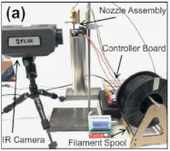
4.1. In-Process Monitoring of Temperature Profile

The objective of the undertaken work is to investigate the in-process monitoring of temperature profiles during deposition. In almost all of the presented works by researchers, combined experimental and numerical simulations were carried out to better realize the temperature evolution of filaments. Up to now, many techniques have been developed to investigate and characterize the temperature evolution during FFF [109]. In order to further understand the characteristics of the recorded temperature profiles, we have divided them into two separate classifications: the global temperature recording on the external surface of deposited layers and the local temperature recording at the interfaces of adjacent layers. In addition, efforts have been taken into account to include experimental/numerical and experimental works in both classifications.

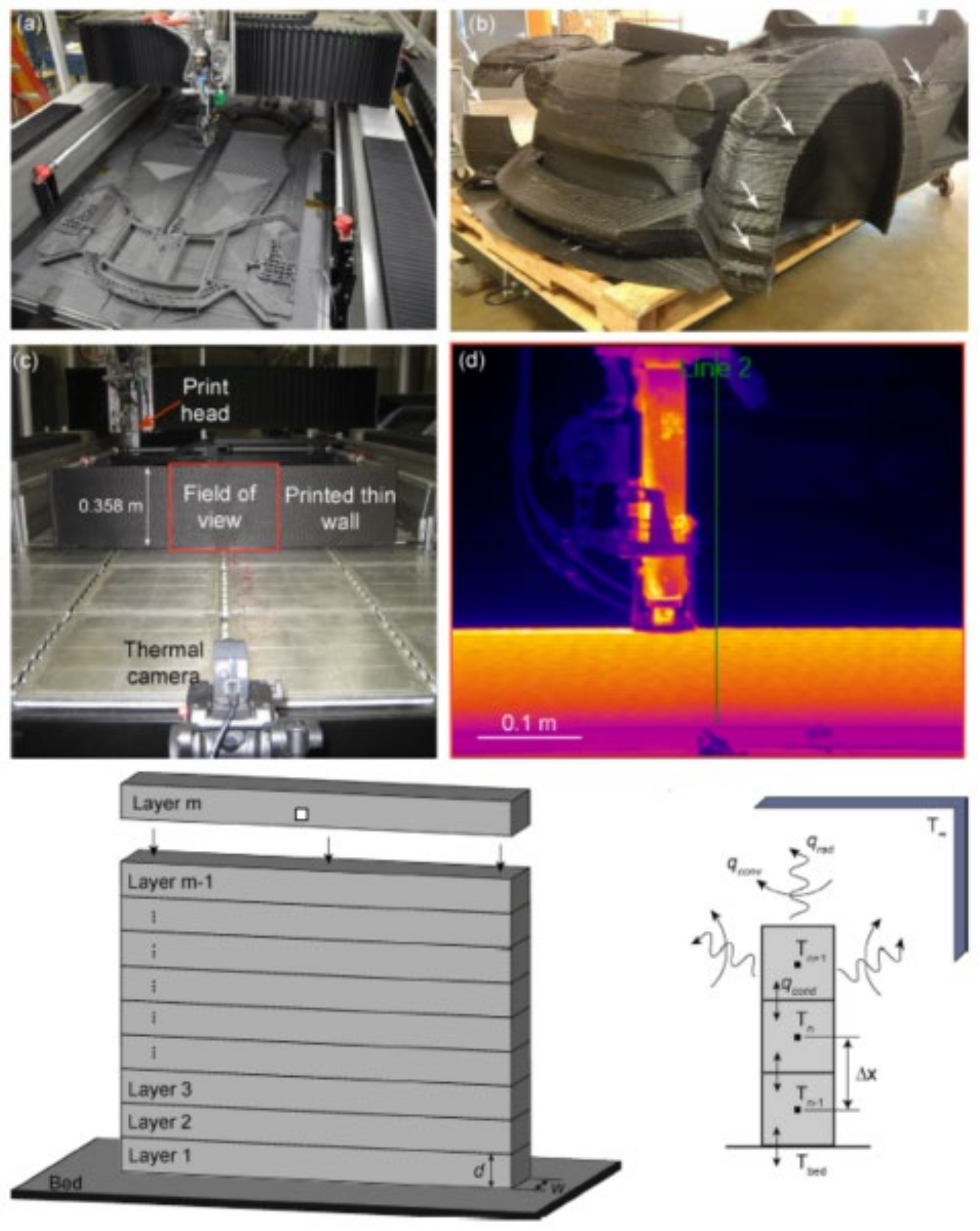
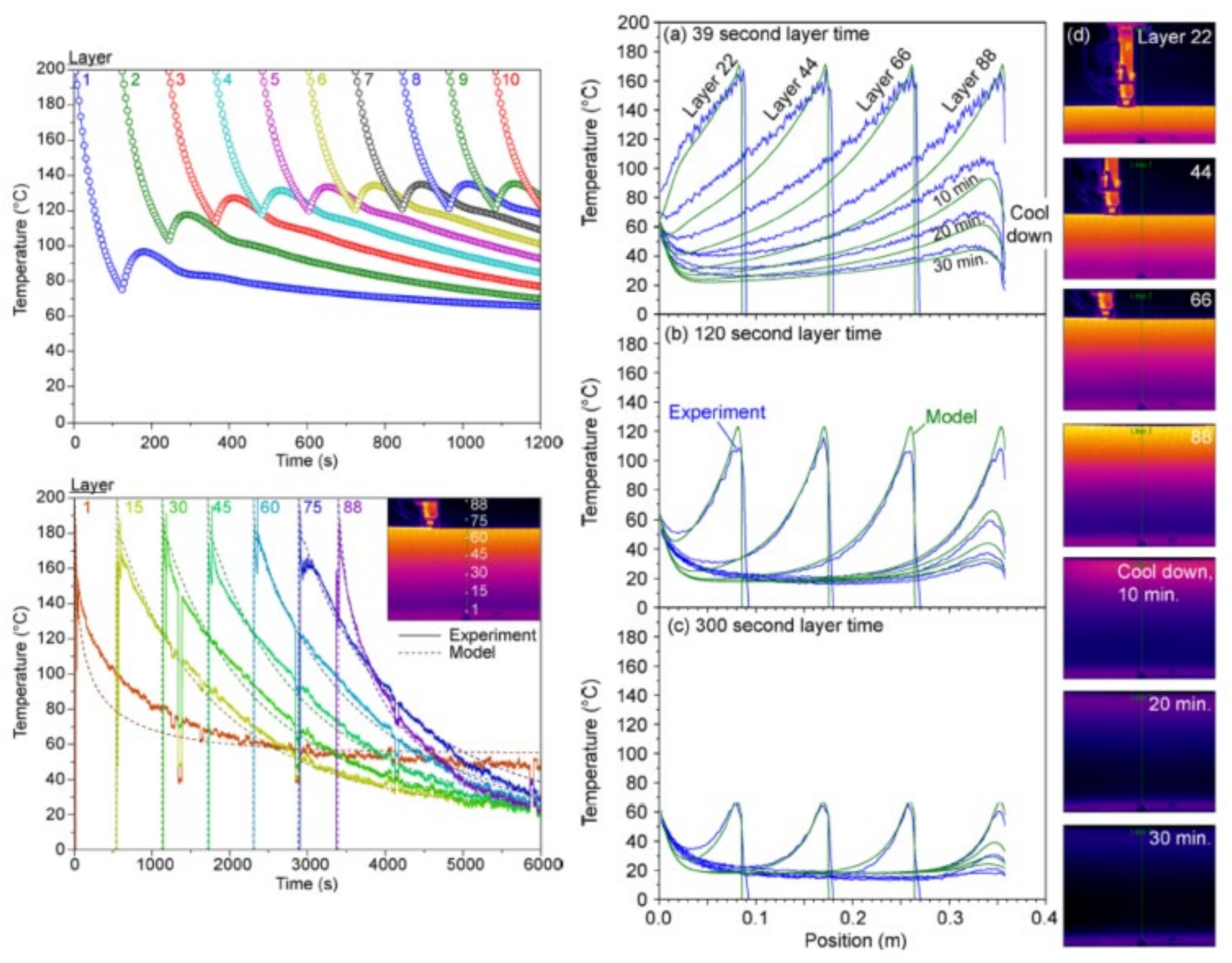
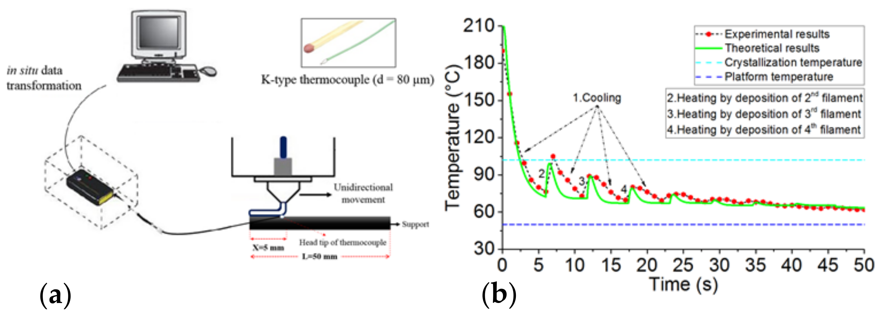
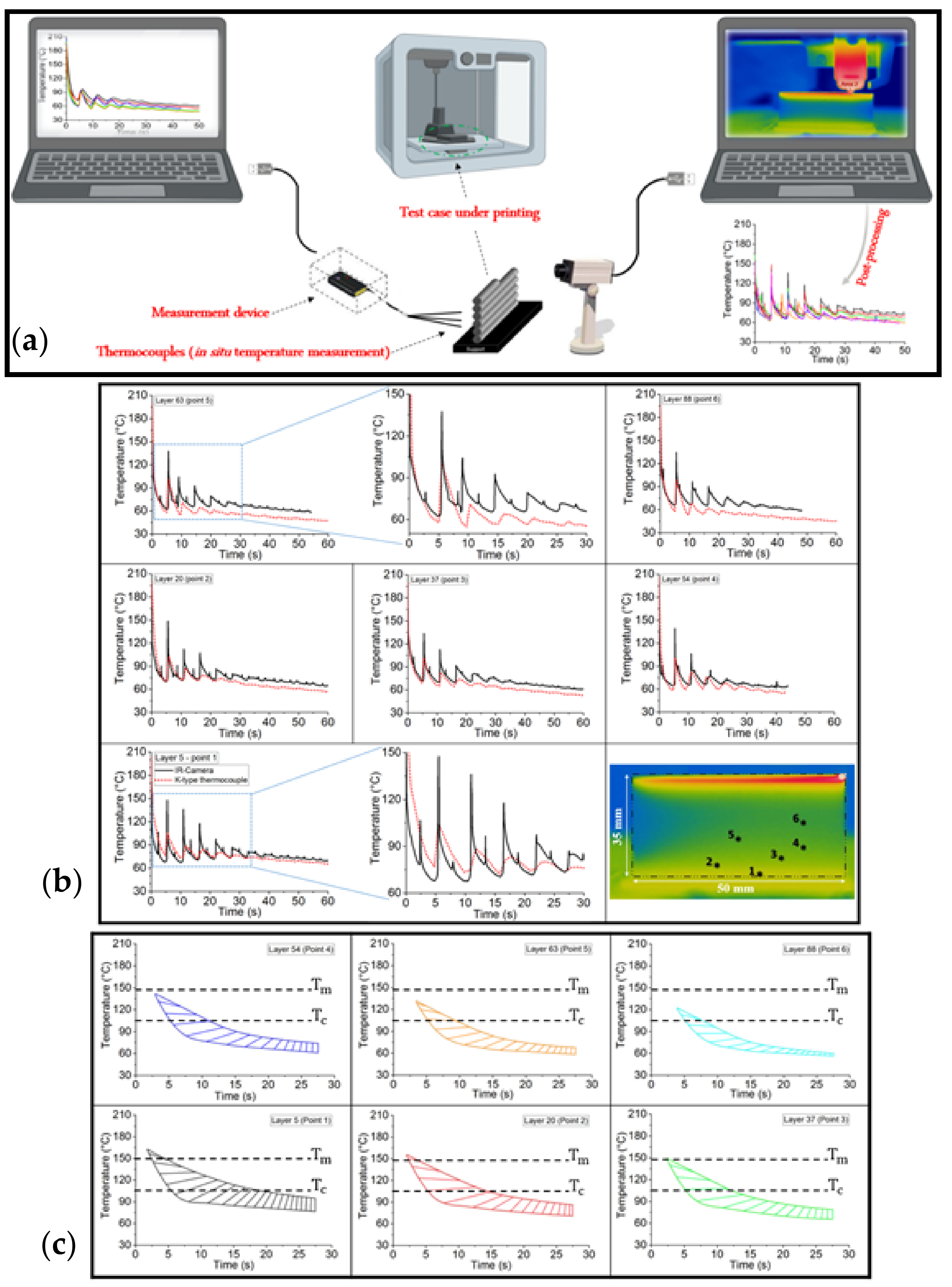
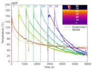
4.1.1. Global Temperature Recording on the External Surface of Deposited Layers

IR cameras are one of the most important and commonly used techniques for monitoring the temperature variation on the external surface of deposited layers [110].
Seppala and Migler [69] utilized infrared thermography to measure filaments’ spatial and temporal temperature profile under several printing conditions. They focused on the weld zone of the active printing region using an in-process recording of temperature using an IR camera. Their results contributed to the estimation of the sublayer heating that is in the melting zone when printing. A year later, they expanded their work by considering the weld formation during material extrusion in FFF by developing an experimental framework consisting of thermal, rheological, and fracture mechanics characterizations [111]. As shown in Figure 5, they measured the temperature profile of the weld zone at different values of the liquefier temperature and print speed. Then, they applied the obtained results for further objectives. A steady increase in the weld strength was observed by increasing the weld time; however, they argued that further investigations are necessary for these statements.
Compton et el. [112] investigated large-scale thermoplastic polymer composites’ temperature evolution using experimental and numerical approaches. The set-up of their experimental work and schematic representation of the 1D thermal model they applied are shown in Figure 6. In fact, the temperature profile of the deposited layers was recorded using thermal imaging, and the results were then applied to a 1D finite difference heat transfer model.
The accompanying graphs in Figure 7 show the temperature evolution of different layers of the designed vertical wall. The following observations were found from both experimentally recorded temperature profiles and the data collected from the developed model:
  • The lower the distance from the platform, the lower the cooling rate;
  • The difference between the onset of the peaks from the obtained results by the IR camera and the developed code shows the limitation of the infrared thermography.
They finally concluded that the temperature of the top layer just before the deposition of a new layer could be considered as an indicator for the degree of warping and cracking.
Apart from the in-process monitoring of the temperature profile through the deposited layers, Prajapati et al. [113] implemented the in-process monitoring of the filament temperature distribution in the stand-off gap between the liquefier and platform (Figure 8). Their model was based on balancing thermal advection and convective/radiative heat loss, including multiple process parameters. They found that the experimental data are in good agreement with the predicted temperature profile.
Rudolph et al. [114] developed a code using the custom python TM program for tool path generation. They also employed infrared thermography on a single wall structure to analyze the cooling and re-heating effect during layer deposition. Using ANSYS® and applying the element death and birth effect, they argued that radiation should be considered as the presence of voids affecting the cooling (or re-heating) rate during deposition.
El Moment et al. [115] studied the temperature and residual stress field by developing a 3D thermo-mechanical model. It includes the temperature-dependent physical properties of the material, such as its density, thermal expansion coefficient, thermal conductivity, yield stress, and Young’s modulus. The quicker the temperature variation, the higher the concentration of the stress, and, thus, the residual thermal stress can cause an offset to the failure envelope.
The experimental and numerical in-process monitoring of temperature profiles during FFF has been developed by several types of research, and is still considered as one of the attractive topics in FFF. Using an infrared-based set-up, Ferraris et al. [116] recorded a vertical wall’s spatial and temporal variations (Figure 9). Although they validated their experimental results with a finite difference method (FDM), the same conclusion was adapted, as discussed in the work of Compton et al. [112]. For example, there is a significant difference through the onset of the peaks between the numerical and experimental results.
Kuznetsov et al. [117] studied the effects of process parameters on the temperature variations at the interface of adjacent layers and how they define the strength of the fabricated parts. They designed tube-shaped samples of rectangular cross-sections. Alongside the mechanical characterizations, the average temperature distribution on the sample surface was recorded using an IR camera (the FLIR tool).
Lepoivre et al. [56] studied the heat transfer and adhesion of the 3D-printed parts by designing a vertical wall as a basis of their work. They used an IR camera to record the temperature profile of filaments experimentally and COMSOL® software to solve the 2D transient heat transfer model. A good agreement was obtained between the experimental and numerical results. Figure 10 briefly shows the experimental set-up, model representation, IR camera thermogram, and the corresponding results.
Basgul et al. [118] proposed a non-isothermal healing model for interfacial strength by developing a 1D heat transfer model. They experimentally measured the temperature profile of a vertical wall utilizing an IR camera and compare the predicted results (Figure 11). Despite the obtained results from the model regarding the degree of healing, a poor agreement was observed through their experimental validations.
A summary of the in-process monitoring of temperature profiles using an IR camera is presented in Table 2.

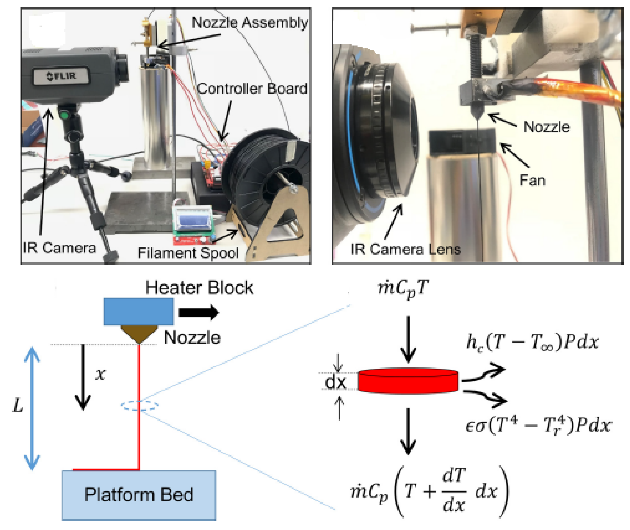
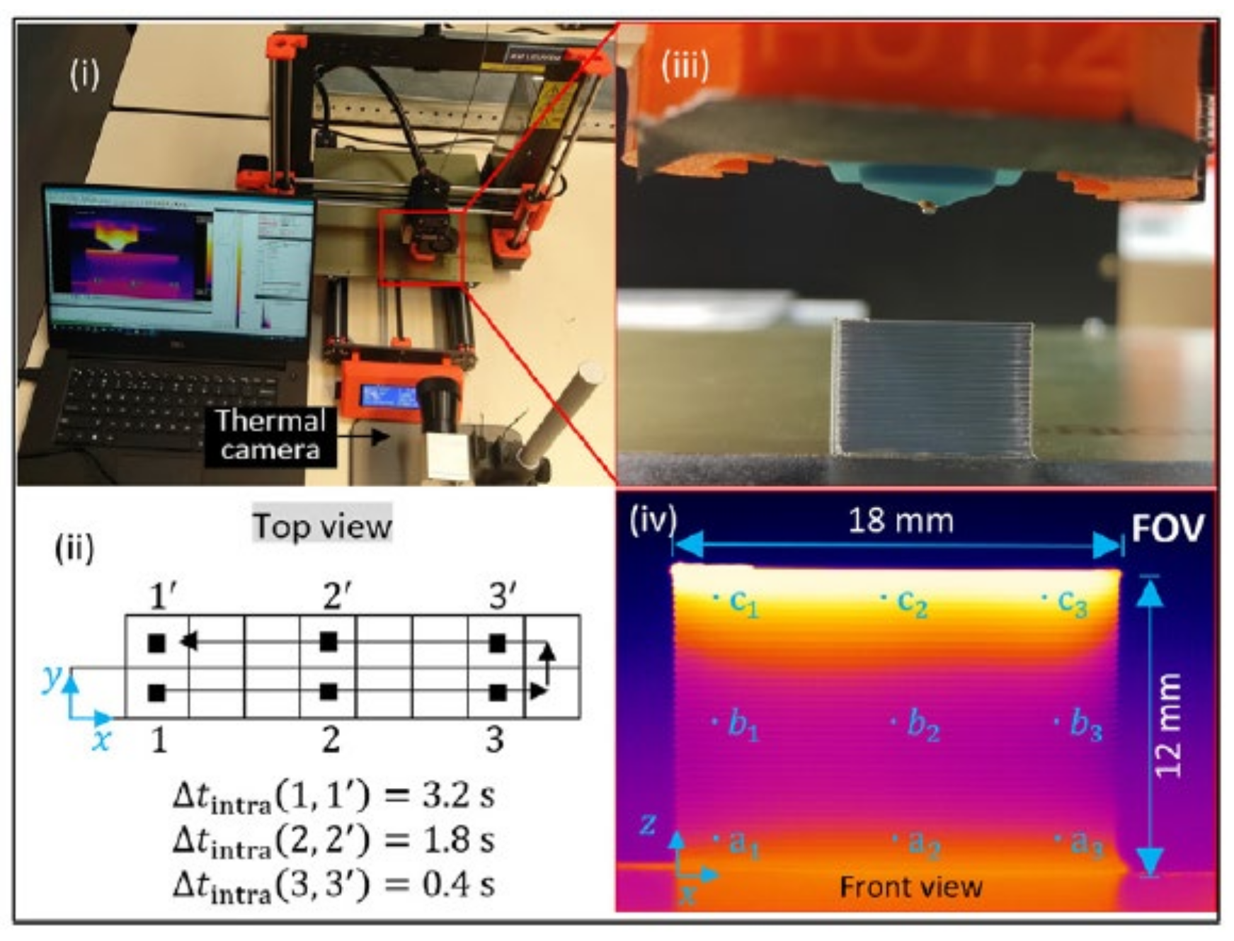
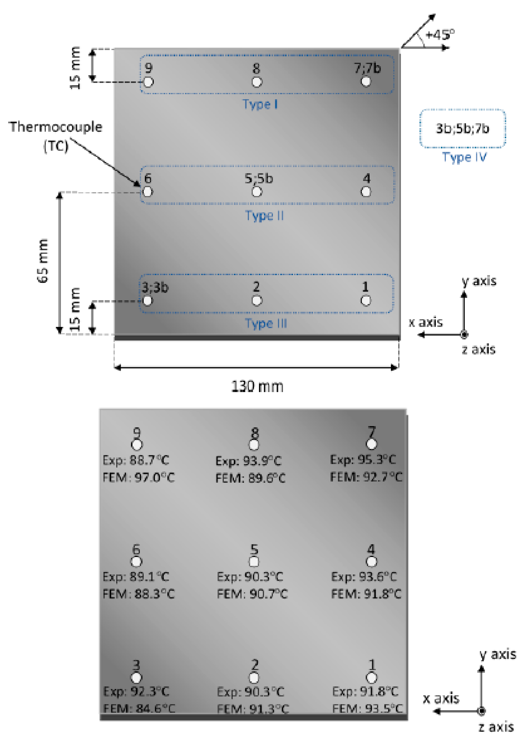
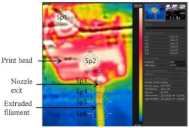
4.1.2. Local Temperature Recording at the Interfaces of Adjacent Layers

The in-process monitoring of the temperature profile should be sufficiently precise and quick in order to track the filament cooling and re-heating peaks arising from the contact between freshly and previously deposited filaments [81,84].
For this reason, Kousiatza and Karalekas [121] investigated in real-time the strain and temperature profile during the fabrication process in FFF by integrating fiber Bragg grating (FBG) sensors. The analysis of their recordings shows that the solidification-induced strain levels and the temperature variations are strongly affected by the position of the sample concerning the building platform. They continued developing their work by proposing an experimental and numerical study toward recording the filament’s temperature during deposition [122]. Comparing the recorded data and predicted results, they found a good agreement (Figure 12). In addition, the obtained peak values express the usefulness of the local measurements.
Yin et al. [123] studied the interfacial bonding during a multi-material deposition in FFF by focusing on the interfacial temperature profiles. They measured the temperature evolution experimentally by adding K-type thermocouples into the layers and validated the obtained results using a 3D transient heat transfer model. A comparison through their results indicated a good agreement with a high difference in the onset of the peaks.
Xu et al. [124] analyzed the temperature evolution of filaments during the fabrication of a thin wall by adding T-type thermocouples. They have also validated their results using a previously developed model [125]. A good agreement was obtained between the recorded data and the numerical simulation; however, the pause while locating the thermocouples was an opposing point of view in this approach.
Vanaei et al. [126] proposed a set-up covering the local in-process monitoring of the temperature profile during the fabrication of a thin wall. They employed very small K-type thermocouples (d = 80 µm) and measured the temperature variation locally without pausing the process (see Figure 13a for a schematic representation of their set-up). They showed a very good agreement between the experimentally recorded data and the predicted results. To be more precise, the onset, relative magnitude, and breadth of the several temperature peaks have been well captured by the proposed approach (Figure 13b).
A thorough investigation of the in-process monitoring of the temperature profile during FFF has been realized in this section. Table 3 briefly summarizes the discussed studies on both the local and global in-process monitoring of temperature profiles.

4.2. Advantages and Limitations of Implemented Approaches

As expressed, local and global in-process temperature monitoring have their advantages and limitations [110]. An IR camera has a limited scan quality in complex geometries, while thermocouples could be fixed to a limited number of points of a geometry [84,127]. With reference to the variety of research in real-time monitoring, particular attention has been paid by Vanaei et al. [128] to carrying out a thorough experimental comparison of the mentioned techniques. As shown in Figure 14a, a schematic representation of the set-up consists of assembling two techniques together: employing K-type thermocouples (d = 80 µm) and an IR camera simultaneously. The obtained results from both approaches with the same conditions, same fixed points of measurement, and being performed simultaneously illustrate the importance of the proposed roadmap. The temperature peaks that the IR camera has recorded were highly overestimated in comparison with the recorded data by K-type thermocouples (Figure 14b). For this reason, the interval of peaks between the two approaches, plotted as contours for corresponding layers, affirm the nature of each measurement technique (Figure 14c).
Given the above-mentioned observations and the presented studies, the advantages and limitations of these approaches have been summarized in Table 4.

5. Summary and Conclusions

FFF unlocks alternative possibilities for the production of complex geometries. In this process, the layer-by-layer deposition mechanism and several heat sources make it a thermally driven process. As heat transfer plays a particular role and determines the temperature history of the merging filaments, the in-process monitoring of the temperature profile guarantees the optimization purposes and thus the part quality improvement.
This review paper summarized the most attractive research on the in-process monitoring of temperature profiles. Detective devices play an essential role through the prosperity of the in-process monitoring of temperature profiles. IR cameras and thermocouples are the most common techniques for this purpose and have attracted much attention from researchers. Furthermore, model-based approaches have also taken a significant role in this regard. We placed special emphasis on highlighting the local and global in-process monitoring techniques in order to carry out their findings and provide an overall comparison between them.
With reference to both experimental and numerical efforts, significant progress has resulted from the in-process monitoring of temperature profiles. However, it was found that a precise approach is still required to be developed for the monitoring of the temperature profile and, consequently, for optimization purposes.

Author Contributions

Conceptualization, S.K. and A.T.; methodology, H.R.V., S.K., M.D., A.T. and M.S.; software, H.R.V. and S.K.; validation, H.R.V., S.K., M.D., A.T. and M.S.; formal analysis, H.R.V., S.K., A.T. and M.S.; investigation, H.R.V., S.K., A.T. and M.S.; resources, S.K., A.T. and M.S.; data curation, H.R.V., S.K., A.T. and M.S.; writing—original draft preparation, H.R.V., S.K. and A.T.; writing—review and editing, H.R.V., M.D., S.K. and A.T.; visualization, S.K. and A.T.; supervision, S.K. and A.T.; project administration, M.D., S.K. and A.T.; funding acquisition, S.K., M.D., A.T. and M.S. All authors have read and agreed to the published version of the manuscript.

Funding

This research received no external funding.

Institutional Review Board Statement

Not applicable.

Informed Consent Statement

Not applicable.

Data Availability Statement

Not applicable.

Conflicts of Interest

The authors declare no conflict of interest.

References

  1. Hiemenz, J. 3D Printing with FDM: How It Works; Stratasys: Rehovot, Israel, 2011; Volume 1, pp. 1–5. [Google Scholar]
  2. Ashley, S. Rapid prototyping systems. Mech. Eng. 1991, 113, 34. [Google Scholar]
  3. Flowers, J. Rapid Prototyping in Technology. Technol. Teacher 2002, 62, 7–11. [Google Scholar]
  4. Chua, C.K.; Siaw, M.C.; Lin, S.C.; Eu, K.H.; Lew, K.F. Rapid prototyping assisted surgery planning. Int. J. Adv. Manuf. Technol. 1998, 14, 624–630. [Google Scholar] [CrossRef]
  5. Vaezi, M.; Seitz, H.; Yang, S. A review on 3D micro-additive manufacturing technologies. Int. J. Adv. Manuf. Technol. 2013, 67, 1721–1754. [Google Scholar] [CrossRef]
  6. Vanaei, S.; Parizi, M.; Salemizadehparizi, F.; Vanaei, H.R. An overview on materials and techniques in 3d bioprinting toward biomedical application. Eng. Regen. 2021, 2, 1–18. [Google Scholar]
  7. El Magri, A.; Vanaei, S.; Vaudreuil, S. An overview on the influence of process parameters through the characteristic of 3D-printed PEEK and PEI parts. High Perform. Polym. 2021, 33, 862–880. [Google Scholar] [CrossRef]
  8. Sohrabian, M.; Vaseghi, M.; Khaleghi, H.; Dehrooyeh, S.; Kohan, M.S.A. Structural Investigation of Delicate-Geometry Fused Deposition Modeling Additive Manufacturing Scaffolds: Experiment and Analytics. J. Mater. Eng. Perform. 2021, 30, 6529–6541. [Google Scholar] [CrossRef]
  9. Lee, J.-Y.; An, J.; Chua, C.K. Fundamentals and applications of 3D printing for novel materials. Appl. Mater. Today 2017, 7, 120–133. [Google Scholar] [CrossRef]
  10. Kruth, J. Material Incress Manufacturing by Rapid Prototyping Techniques. CIRP Ann. 1991, 40, 603–614. [Google Scholar] [CrossRef]
  11. Chennakesava, P.; Narayan, Y.S. Fused deposition modeling-insights. In Proceedings of the International Conference on Advances in Design and Manufacturing ICAD&M, Tiruchirappalli, Tamil Nadu, India, 5–7 December 2014. [Google Scholar]
  12. de Leon, A.C.; Chen, Q.; Palaganas, N.B.; Palaganas, J.O.; Manapat, J.; Advincula, R.C. High performance polymer nanocomposites for additive manufacturing applications. React. Funct. Polym. 2016, 103, 141–155. [Google Scholar] [CrossRef]
  13. Wang, X.; Jiang, M.; Zhou, Z.; Gou, J.; Hui, D. 3D printing of polymer matrix composites: A review and prospective. Compos. Part B Eng. 2017, 110, 442–458. [Google Scholar] [CrossRef]
  14. Wohlers, T.; Gornet, T. History of additive manufacturing. Wohlers Rep. 2014, 24, 118. [Google Scholar]
  15. El Magri, A.; Mabrouk, K.E.; Vaudreuil, S. Preparation and characterization of poly (ether ether ketone)/poly (ether imide)[PEEK/PEI] blends for fused filament fabrication. J. Mater. Sci. 2021, 56, 14348–14367. [Google Scholar] [CrossRef]
  16. Dakshinamurthy, D.; Gupta, S. A Study on the Influence of Process Parameters on the Viscoelastic Properties of ABS Components Manufactured by FDM Process. J. Inst. Eng. (India) Ser. C 2018, 99, 133–138. [Google Scholar] [CrossRef]
  17. El Magri, A.; Vanaei, S.; Shirinbayan, M.; Vaudreuil, S.; Tcharkhtchi, A. An Investigation to Study the Effect of Process Parameters on the Strength and Fatigue Behavior of 3D-Printed PLA-Graphene. Polymers 2021, 13, 3218. [Google Scholar] [CrossRef]
  18. Crump, S.S. Fast, precise, safe prototypes with FDM. ASME PED 1991, 50, 53–60. [Google Scholar]
  19. Magri, A.E.; Mabrouk, K.E.; Vaudreuil, S.; Touhami, M.E. Mechanical properties of CF-reinforced PLA parts manufactured by fused deposition modeling. J. Thermoplast. Compos. Mater. 2021, 34, 581–595. [Google Scholar]
  20. EL Magri, A.; El Mabrouk, K.; Vaudreuil, S.; Touhami, M.E. Experimental investigation and optimization of printing parameters of 3D printed polyphenylene sulfide through response surface methodology. J. Appl. Polym. Sci. 2021, 138, 49625. [Google Scholar] [CrossRef]
  21. De Pieri, A.; Byerley, A.M.; Musumeci, C.R.; Salemizadehparizi, F.; Vanderhorst, M.A.; Wuertz-Kozak, K. Electrospinning and 3D bioprinting for intervertebral disc tissue engineering. JOR Spine 2020, 3, 1117. [Google Scholar] [CrossRef]
  22. Vanaei, H.R.; Raissi, K.; Deligant, M.; Shirinbayan, M.; Fitoussi, J.; Khelladi, S.; Tcharkhtchi, A. Toward the understanding of temperature effect on bonding strength, dimensions and geometry of 3D-printed parts. J. Mater. Sci. 2020, 55, 14677–14689. [Google Scholar] [CrossRef]
  23. El Magri, A.; Vaudreuil, S.; El Mabrouk, K.; Touhami, M.E. Printing temperature effects on the structural and mechanical performances of 3D printed Poly-(phenylene sulfide) material. In IOP Conference Series: Materials Science and Engineering; IOP Publishing: Bristol, UK, 2020; Volume 783, p. 012001. [Google Scholar] [CrossRef]
  24. Vanaei, H.R.; Shirinbayan, M.; Vanaei, S.; Fitoussi, J.; Khelladi, S.; Tcharkhtchi, A. Multi-scale damage analysis and fatigue behavior of PLA manufactured by fused deposition modeling (FDM). Rapid Prototyp. J. 2021, 27, 371–378. [Google Scholar] [CrossRef]
  25. Vanaei, H.; Shirinbayan, M.; Deligant, M.; Raissi, K.; Fitoussi, J.; Khelladi, S.; Tcharkhtchi, A. Influence of process parameters on thermal and mechanical properties of polylactic acid fabricated by fused filament fabrication. Polym. Eng. Sci. 2020, 60, 1822–1831. [Google Scholar] [CrossRef]
  26. Dizon, J.R.C.; Espera, A.H.; Chen, Q.; Advincula, R.C. Mechanical characterization of 3D-printed polymers. Addit. Manuf. 2018, 20, 44–67. [Google Scholar] [CrossRef]
  27. Turner, B.N.; Strong, R.; Gold, S.A. A review of melt extrusion additive manufacturing processes: I. Process Design Modeling Rapid Prototyp. J. 2014, 20, 192–204. [Google Scholar] [CrossRef]
  28. Turner, B.N.; A Gold, S. A review of melt extrusion additive manufacturing processes: II. Materials, dimensional accuracy, and surface roughness. Rapid Prototyp. J. 2015, 21, 250–261. [Google Scholar] [CrossRef]
  29. Parandoush, P.; Lin, D. A review on additive manufacturing of polymer-fiber composites. Compos. Struct. 2017, 182, 36–53. [Google Scholar] [CrossRef]
  30. Das, A.; McIlroy, C.; Bortner, M.J. Advances in modeling transport phenomena in material-extrusion additive manufacturing: Coupling momentum, heat, and mass transfer. Prog. Addit. Manuf. 2021, 6, 3–17. [Google Scholar] [CrossRef]
  31. Ahn, S.; Montero, M.; Odell, D.; Roundy, S.; Wright, P.K. Anisotropic material properties of fused deposition modeling ABS. Rapid Prototyp. J. 2002, 8, 248–257. [Google Scholar] [CrossRef] [Green Version]
  32. Caminero, M.Á.; Chacón, J.M.; García-Plaza, E.; Núñez, P.J.; Reverte, J.M.; Becar, J.P. Additive Manufacturing of PLA-Based Composites Using Fused Filament Fabrication: Effect of Graphene Nanoplatelet Reinforcement on Mechanical Properties, Dimensional Accuracy and Texture. Polymers 2019, 11, 799. [Google Scholar] [CrossRef] [Green Version]
  33. Buj-Corral, I.; Bagheri, A.; Sivatte-Adroer, M. Effect of Printing Parameters on Dimensional Error, Surface Roughness and Porosity of FFF Printed Parts with Grid Structure. Polymers 2021, 13, 1213. [Google Scholar] [CrossRef] [PubMed]
  34. Pennington, R.C.; Hoekstra, N.L.; Newcomer, J.L. Significant factors in the dimensional accuracy of fused deposition modelling. Proc. Inst. Mech. Eng. Part E J. Process. Mech. Eng. 2005, 219, 89–92. [Google Scholar] [CrossRef]
  35. Chaidas, D.; Kitsakis, K.; Kechagias, J.; Maropoulos, S. The impact of temperature changing on surface roughness of FFF process. In IOP Conference Series: Materials Science and Engineering; IOP Publishing: Bristol, UK, 2016; Volume 161, p. 012033. [Google Scholar] [CrossRef] [Green Version]
  36. Aslani, K.-E.; Chaidas, D.; Kechagias, J.; Kyratsis, P.; Salonitis, K. Quality Performance Evaluation of Thin Walled PLA 3D Printed Parts Using the Taguchi Method and Grey Relational Analysis. J. Manuf. Mater. Process. 2020, 4, 47. [Google Scholar] [CrossRef]
  37. Katti, D.; Sharma, A.; Katti, K. Predictive Methodologies for Design of Bone Tissue Engineering Scaffolds. In Materials for Bone Disorders; Elsevier BV: Amsterdam, The Netherlands, 2017; pp. 453–492. [Google Scholar]
  38. Górski, F.; Wichniarek, R.; Kuczko, W.; Zawadzki, P.; Buń, P. Strength of abs parts produced by fused deposition modelling technology—A critical orientation problem. Adv. Sci. Technol. Res. J. 2015, 9, 12–19. [Google Scholar] [CrossRef] [Green Version]
  39. Lee, C.; Kim, S.; Kim, H.; Ahn, S. Measurement of anisotropic compressive strength of rapid prototyping parts. J. Mater. Process. Technol. 2007, 187–188, 627–630. [Google Scholar] [CrossRef]
  40. Es-Said, O.S.; Foyos, J.; Noorani, R.; Mendelson, M.; Marloth, R.; Pregger, B.A. Effect of Layer Orientation on Mechanical Properties of Rapid Prototyped Samples. Mater. Manuf. Process. 2000, 15, 107–122. [Google Scholar] [CrossRef]
  41. Smith, W.C.; Dean, R.W. Structural characteristics of fused deposition modeling polycarbonate material. Polym. Test. 2013, 32, 1306–1312. [Google Scholar] [CrossRef]
  42. Schöppner, V.; Ktp, K.P. Mechanical properties of fused deposition modeling parts manufactured with Ultem * 9085. In Proceedings of the 69th Annual Technical Conference of the Society of Plastics Engineers (ANTEC’11), Boston, MA, USA, 1–5 May 2011. [Google Scholar]
  43. EL Magri, A.; El Mabrouk, K.; Vaudreuil, S.; Chibane, H.; Touhami, M.E. Optimization of printing parameters for improvement of mechanical and thermal performances of 3D printed poly(ether ether ketone) parts. J. Appl. Polym. Sci. 2020, 137, 49087. [Google Scholar] [CrossRef]
  44. Wang, P.; Zou, B.; Xiao, H.; Ding, S.; Huang, C. Effects of printing parameters of fused deposition modeling on mechanical properties, surface quality, and microstructure of PEEK. J. Mater. Process. Technol. 2019, 271, 62–74. [Google Scholar] [CrossRef]
  45. Wu, W.; Geng, P.; Li, G.; Zhao, D.; Zhang, H.; Zhao, J. Influence of Layer Thickness and Raster Angle on the Mechanical Properties of 3D-Printed PEEK and a Comparative Mechanical Study between PEEK and ABS. Materials 2015, 8, 5834–5846. [Google Scholar] [CrossRef]
  46. Rahman, K.M.; Letcher, T.; Reese, R. Mechanical properties of additively manufactured PEEK components using fused filament fabrication. In ASME International Mechanical Engineering Congress and Exposition; American Society of Mechanical Engineers: New York, NY, USA, 2015. [Google Scholar]
  47. Byberg, K.I.; Gebisa, A.W.; Lemu, H.G. Mechanical properties of ULTEM 9085 material processed by fused deposition modeling. Polym. Test. 2018, 72, 335–347. [Google Scholar] [CrossRef]
  48. Forés-Garriga, A.; Pérez, M.A.; Gómez-Gras, G.; Pozo, G.R. Role of infill parameters on the mechanical performance and weight reduction of PEI Ultem processed by FFF. Mater. Des. 2020, 193, 108810. [Google Scholar] [CrossRef]
  49. Masood, S.; Mau, K.; Song, W. Tensile Properties of Processed FDM Polycarbonate Material. Mater. Sci. Forum 2010, 654-656, 2556–2559. [Google Scholar] [CrossRef]
  50. Motaparti, K.P.; Taylor, G.; Leu, M.; Chandrashekhara, K.; Castle, J.; Matlack, M. Effects of build parameters on compression properties for ULTEM 9085 parts by fused deposition modeling. In Proceedings of the 27th Annual International Solid Freeform Fabrication Symposium, Austin, TX, USA, 8–10 August 2016. [Google Scholar]
  51. Lee, B.; Abdullah, J.; Khan, Z. Optimization of rapid prototyping parameters for production of flexible ABS object. J. Mater. Process. Technol. 2005, 169, 54–61. [Google Scholar] [CrossRef]
  52. Casavola, C.; Cazzato, A.; Moramarco, V.; Pappalettere, C. Orthotropic mechanical properties of fused deposition modelling parts described by classical laminate theory. Mater. Design 2016, 90, 453–458. [Google Scholar] [CrossRef]
  53. Rathee, S.; Srivastava, M.; Maheshwari, S.; Siddiquee, A. Effect of varying spatial orientations on build time requirements for FDM process: A case study. Def. Technol. 2017, 13, 92–100. [Google Scholar] [CrossRef]
  54. Rodriguez, J.F.; Thomas, J.P.; Renaud, J.E. Characterization of the mesostructure of fused-deposition acrylonitrile-butadiene-styrene materials. Rapid Prototyp. J. 2000, 6, 175–186. [Google Scholar] [CrossRef]
  55. Bellehumeur, C.; Li, L.; Sun, Q.; Gu, P. Modeling of Bond Formation Between Polymer Filaments in the Fused Deposition Modeling Process. J. Manuf. Process. 2004, 6, 170–178. [Google Scholar] [CrossRef]
  56. Lepoivre, A.; Boyard, N.; Levy, A.; Sobotka, V. Heat Transfer and Adhesion Study for the FFF Additive Manufacturing Process. Procedia Manuf. 2020, 47, 948–955. [Google Scholar] [CrossRef]
  57. Costa, S.F.; Duarte, F.; Covas, J. Towards modelling of Free Form Extrusion: Analytical solution of transient heat transfer. Int. J. Mater. Form. 2008, 1, 703–706. [Google Scholar] [CrossRef]
  58. Costa, S.; Duarte, F.; Covas, J. Thermal conditions affecting heat transfer in FDM/FFE: A contribution towards the numerical modelling of the process: This paper investigates convection, conduction and radiation phenomena in the filament deposition process. Virtual Phys. Prototyp. 2015, 10, 35–46. [Google Scholar] [CrossRef]
  59. Thomas, J.; Rodríguez, J. Modeling the fracture strength between fused-deposition extruded roads 16. In Proceedings of the 2000 International Solid Freeform Fabrication Symposium, Austin, TX, USA, 7–9 August 2000. [Google Scholar]
  60. Yardimci, M.A.; Güçeri, S. Conceptual framework for the thermal process modelling of fused deposition. Rapid Prototyp. J. 1996, 2, 26–31. [Google Scholar] [CrossRef]
  61. AtifYardimci, M.; Hattori, T.; Guceri, S.I.; Danforth, S.C. Thermal analysis of fused deposition. In Proceedings of the 1997 International Solid Freeform Fabrication Symposium, Austin, TX, USA, 11–13 August 1997. [Google Scholar]
  62. Zhang, Y.; Chou, Y.K. Three-dimensional finite element analysis simulations of the fused deposition modelling process. Proc. Inst. Mech. Eng. Part B J. Eng. Manuf. 2006, 220, 1663–1671. [Google Scholar] [CrossRef]
  63. Ji, L.B.; Zhou, T.R. Finite Element Simulation of Temperature Field in Fused Deposition Modeling. Adv. Mater. Res. 2010, 97–101, 2585–2588. [Google Scholar] [CrossRef]
  64. Crump, S.S. Modeling Apparatus for Three-Dimensional Objects. U.S. Patent 5340433A, 23 August 1994. [Google Scholar]
  65. Peng, F.; Vogt, B.D.; Cakmak, M. Complex flow and temperature history during melt extrusion in material extrusion additive manufacturing. Addit. Manuf. 2018, 22, 197–206. [Google Scholar] [CrossRef]
  66. Serdeczny, M.P.; Comminal, R.; Pedersen, D.B.; Spangenberg, J. Experimental and analytical study of the polymer melt flow through the hot-end in material extrusion additive manufacturing. Addit. Manuf. 2020, 32, 100997. [Google Scholar] [CrossRef]
  67. Vaes, D.; Coppens, M.; Goderis, B.; Zoetelief, W.; Van Puyvelde, P. Assessment of Crystallinity Development during Fused Filament Fabrication through Fast Scanning Chip Calorimetry. Appl. Sci. 2019, 9, 2676. [Google Scholar] [CrossRef] [Green Version]
  68. Cattenone, A.; Morganti, S.; Alaimo, G.; Auricchio, F. Finite Element Analysis of Additive Manufacturing Based on Fused Deposition Modeling: Distortions Prediction and Comparison With Experimental Data. J. Manuf. Sci. Eng. 2018, 141, 011010. [Google Scholar] [CrossRef]
  69. Seppala, J.E.; Migler, K.D. Infrared thermography of welding zones produced by polymer extrusion additive manufacturing. Addit. Manuf. 2016, 12, 71–76. [Google Scholar] [CrossRef] [Green Version]
  70. D’Amico, A.; Peterson, A.M. An adaptable FEA simulation of material extrusion additive manufacturing heat transfer in 3D. Addit. Manuf. 2018, 21, 422–430. [Google Scholar] [CrossRef]
  71. Costa, S.; Duarte, F.; Covas, J. Estimation of filament temperature and adhesion development in fused deposition techniques. J. Mater. Process. Technol. 2017, 245, 167–179. [Google Scholar] [CrossRef]
  72. Chacón, J.M.; Caminero, M.A.; García-Plaza, E.; Núñez, P.J. Additive manufacturing of PLA structures using fused deposition modelling: Effect of process parameters on mechanical properties and their optimal selection. Mater. Des. 2017, 124, 143–157. [Google Scholar] [CrossRef]
  73. Coogan, T.J.; Kazmer, D.O. Bond and part strength in fused deposition modeling. Rapid Prototyp. J. 2017, 23, 414–422. [Google Scholar] [CrossRef]
  74. Jatti, V.S.; Jatti, S.V.; Patel, A.P.; Jatti, V.S. A Study on Effect of Fused Deposition Modeling Process Parameters on Mechanical Properties. Int. J. Sci. Technol. Res. 2019, 8, 689–693. [Google Scholar]
  75. Ning, F.; Cong, W.; Hu, Y.; Wang, H. Additive manufacturing of carbon fiber-reinforced plastic composites using fused deposition modeling: Effects of process parameters on tensile properties. J. Compos. Mater. 2017, 51, 451–462. [Google Scholar] [CrossRef]
  76. Guessasma, S.; Belhabib, S.; Nouri, H. Thermal cycling, microstructure and tensile performance of PLA-PHA polymer printed using fused deposition modelling technique. Rapid Prototyp. J. 2020, 26, 122–133. [Google Scholar] [CrossRef]
  77. Jiang, S.; Liao, G.; Xu, D.; Liu, F.; Li, W.; Cheng, Y.; Li, Z.; Xu, G. Mechanical properties analysis of polyetherimide parts fabricated by fused deposition modeling. High Perform. Polym. 2019, 31, 97–106. [Google Scholar] [CrossRef]
  78. Yang, C.; Tian, X.; Li, D.; Cao, Y.; Zhao, F.; Shi, C. Influence of thermal processing conditions in 3D printing on the crystallinity and mechanical properties of PEEK material. J. Mater. Process. Technol. 2017, 248, 1–7. [Google Scholar] [CrossRef]
  79. Ding, S.; Zou, B.; Wang, P.; Ding, H. Effects of nozzle temperature and building orientation on mechanical properties and microstructure of PEEK and PEI printed by 3D-FDM. Polym. Test. 2019, 78, 105948. [Google Scholar] [CrossRef]
  80. Berretta, S.; Davies, R.; Shyng, Y.; Wang, Y.; Ghita, O. Fused Deposition Modelling of high temperature polymers: Exploring CNT PEEK composites. Polym. Test. 2017, 63, 251–262. [Google Scholar] [CrossRef]
  81. Monzón, M.D.; Gibson, I.; Benítez, A.N.; Lorenzo, L.; Hernández, P.M.; Marrero, M.D. Process and material behavior modeling for a new design of micro-additive fused deposition. Int. J. Adv. Manuf. Technol. 2013, 67, 2717–2726. [Google Scholar] [CrossRef]
  82. Xiaoyong, S.; LiangCheng, C.; Honglin, M.; Peng, G.; Zhanwei, B.; Cheng, L. Experimental Analysis of High Temperature PEEK Materials on 3D Printing Test. In Proceedings of the 2017 9th International Conference on Measuring Technology and Mechatronics Automation (ICMTMA), Changsha, China, 14–15 January 2017; Institute of Electrical and Electronics Engineers (IEEE): New York, NY, USA, 2017; pp. 13–16. [Google Scholar]
  83. Aliheidari, N.; Tripuraneni, R.; Ameli, A.; Nadimpalli, S. Fracture resistance measurement of fused deposition modeling 3D printed polymers. Polym. Test. 2017, 60, 94–101. [Google Scholar] [CrossRef]
  84. Sun, Q.; Rizvi, G.M.; Bellehumeur, C.T.; Gu, P. Effect of processing conditions on the bonding quality of FDM polymer filaments. Rapid Prototyp. J. 2008, 14, 72–80. [Google Scholar] [CrossRef]
  85. Christiyan, K.G.J.; Chandrasekhar, U.; Venkateswarlu, K. A study on the influence of process parameters on the Mechanical Properties of 3D printed ABS composite. In IOP Conference Series: Materials Science and Engineering; IOP Publishing: Bristol, UK; p. 012109.
  86. Abeykoon, C.; Sri-Amphorn, P.; Fernando, A. Optimization of fused deposition modeling parameters for improved PLA and ABS 3D printed structures. Int. J. Lightweight Mater. Manuf. 2020, 3, 284–297. [Google Scholar] [CrossRef]
  87. Geng, P.; Zhao, J.; Wu, W.; Ye, W.; Wang, Y.; Wang, S.; Zhang, S. Effects of extrusion speed and printing speed on the 3D printing stability of extruded PEEK filament. J. Manuf. Process. 2019, 37, 266–273. [Google Scholar] [CrossRef]
  88. Jiang, Z.; Diggle, B.; Tan, M.L.; Viktorova, J.; Bennett, C.W.; Connal, L.A. Extrusion 3D Printing of Polymeric Materials with Advanced Properties. Adv. Sci. 2020, 7, 2001379. [Google Scholar] [CrossRef]
  89. Scheithauer, U.; Schwarzer, E.; Richter, H.-J.; Moritz, T. Thermoplastic 3D Printing-An Additive Manufacturing Method for Producing Dense Ceramics. Int. J. Appl. Ceram. Technol. 2014, 12, 26–31. [Google Scholar] [CrossRef]
  90. Comminal, R.; Pimenta, F.; Hattel, J.; Alves, M.; Spangenberg, J. Numerical simulation of the planar extrudate swell of pseudoplastic and viscoelastic fluids with the streamfunction and the VOF methods. J. Non-Newtonian Fluid Mech. 2018, 252, 1–18. [Google Scholar] [CrossRef]
  91. Xia, H.; Lu, J.; Tryggvason, G. A numerical study of the effect of viscoelastic stresses in fused filament fabrication. Comput. Methods Appl. Mech. Eng. 2019, 346, 242–259. [Google Scholar] [CrossRef]
  92. Du, J.; Wei, Z.; Wang, X.; Wang, J.; Chen, Z. An improved fused deposition modeling process for forming large-size thin-walled parts. J. Mater. Process. Technol. 2016, 234, 332–341. [Google Scholar] [CrossRef]
  93. Liu, J.; Anderson, K.L.; Sridhar, N. Direct Simulation of Polymer Fused Deposition Modeling (FDM)—An Implementation of the Multi-Phase Viscoelastic Solver in OpenFOAM. Int. J. Comput. Methods 2020, 17, 1844002. [Google Scholar] [CrossRef] [Green Version]
  94. Duty, C.; Ajinjeru, C.; Kishore, V.; Compton, B.; Hmeidat, N.; Chen, X.; Liu, P.; Hassen, A.A.; Lindahl, J.; Kunc, V. What makes a material printable? A viscoelastic model for extrusion-based 3D printing of polymers. J. Manuf. Process. 2018, 35, 526–537. [Google Scholar] [CrossRef]
  95. Fitzpatrick, J.; Descamps, N.; O’Meara, K.; Jones, C.; Walsh, D.; Spitere, M. Comparing the caking behaviours of skim milk powder, amorphous maltodextrin and crystalline common salt. Powder Technol. 2010, 204, 131–137. [Google Scholar] [CrossRef]
  96. Kasmaee, M.; Varaminian, F.; Khadiv-Parsi, P.; Saien, J. Effects of different surfactants and physical properties on the coalescence of dimethyl disulfide drops with mother phase at the interface of sodium hydroxide aqueous solutions. J. Mol. Liq. 2018, 263, 31–39. [Google Scholar] [CrossRef]
  97. Gross, M.; Steinbach, I.; Raabe, D.; Varnik, F. Viscous coalescence of droplets: A lattice Boltzmann study. Phys. Fluids 2013, 25, 052101. [Google Scholar] [CrossRef] [Green Version]
  98. Kamyabi, M.; Sotudeh-Gharebagh, R.; Zarghami, R.; Saleh, K. Principles of viscous sintering in amorphous powders: A critical review. Chem. Eng. Res. Des. 2017, 125, 328–347. [Google Scholar] [CrossRef]
  99. Frenkel, J. Viscous flow of crystalline bodies under the action of surface tension. J. Phys. 1945, 9, 385. [Google Scholar]
  100. Pokluda, O.; Bellehumeur, C.T.; Vlachopoulos, J. Modification of Frenkel’s model for sintering. AIChE J. 1997, 43, 3253–3256. [Google Scholar] [CrossRef]
  101. Bellehumeur, C.T.; Bisaria, M.K.; Vlachopoulos, J. An experimental study and model assessment of polymer sintering. Polym. Eng. Sci. 1996, 36, 2198–2207. [Google Scholar] [CrossRef]
  102. Hopper, R.W. Coalescence of Two Equal Cylinders: Exact Results for Creeping Viscous Plane Flow Driven by Capillarity. J. Am. Ceram. Soc. 1984, 67, C-262. [Google Scholar] [CrossRef]
  103. Tarafdar, R.M.; Bergman, T.L. Detailed Numerical and Experimental Investigation of Non-Isothermal Sintering of Amorphous Polymer Material. J. Heat Transf. 2002, 124, 553–563. [Google Scholar] [CrossRef]
  104. Wadsworth, F.B.; Vasseur, J.; Von Aulock, F.W.; Hess, K.-U.; Scheu, B.; Lavallée, Y.; Dingwell, D.B. Nonisothermal viscous sintering of volcanic ash. J. Geophys. Res. Solid Earth 2014, 119, 8792–8804. [Google Scholar] [CrossRef]
  105. Bhalodi, D.; Zalavadiya, K.; Gurrala, P.K. Influence of temperature on polymer parts manufactured by fused deposition modeling process. J. Braz. Soc. Mech. Sci. Eng. 2019, 41, 113. [Google Scholar] [CrossRef]
  106. Polychronopoulos, N.D.; Vlachopoulos, J. The role of heating and cooling in viscous sintering of pairs of spheres and pairs of cylinders. Rapid Prototyp. J. 2020, 26, 719–726. [Google Scholar] [CrossRef]
  107. Zhang, J.; Wang, X.; Yu, W.; Deng, Y. Numerical investigation of the influence of process conditions on the temperature variation in fused deposition modeling. Mater. Design 2017, 130, 59–68. [Google Scholar] [CrossRef]
  108. Zhang, Y.; Shapiro, V. Linear time thermal simulation of fdm process. In International Design Engineering Technical Conferences and Computers and Information in Engineering Conference; American Society of Mechanical Engineers: New York, NY, USA, 2017. [Google Scholar]
  109. Pourali, M.; Peterson, A.M. Thermal modeling of material extrusion additive manufacturing. In Polymer-Based Additive Manufacturing: Recent Developments; American Chemical Society (ACS): Washington, DC, USA, 2019; pp. 115–130. [Google Scholar]
  110. Zhou, X.; Hsieh, S.-J. Thermal analysis of fused deposition modeling process using infrared thermography imaging and finite element modeling. In Thermosense: Thermal Infrared Applications XXXIX; SPIE: Washington, DC, USA, 2017; p. 1021409. [Google Scholar]
  111. Seppala, J.E.; Han, S.H.; Hillgartner, K.E.; Davis, C.S.; Migler, K.B. Weld formation during material extrusion additive manufacturing. Soft Matter 2017, 13, 6761–6769. [Google Scholar] [CrossRef]
  112. Compton, B.G.; Post, B.K.; Duty, C.E.; Love, L.; Kunc, V. Thermal analysis of additive manufacturing of large-scale thermoplastic polymer composites. Addit. Manuf. 2017, 17, 77–86. [Google Scholar] [CrossRef]
  113. Prajapati, H.; Ravoori, D.; Jain, A. Measurement and modeling of filament temperature distribution in the standoff gap between nozzle and bed in polymer-based additive manufacturing. Addit. Manuf. 2018, 24, 224–231. [Google Scholar] [CrossRef]
  114. Rudolph, N.; Chen, J.; Dick, T. Understanding the temperature field in fused filament fabrication for enhanced mechanical part performance. In AIP Conference Proceedings; AIP Publishing LLC: Melville, NY, USA, 2019. [Google Scholar]
  115. El Moumen, A.; Tarfaoui, M.; Lafdi, K. Modelling of the temperature and residual stress fields during 3D printing of polymer composites. Int. J. Adv. Manuf. Technol. 2019, 104, 1661–1676. [Google Scholar] [CrossRef]
  116. Ferraris, E.; Zhang, J.; Van Hooreweder, B. Thermography based in-process monitoring of Fused Filament Fabrication of polymeric parts. CIRP Ann. 2019, 68, 213–216. [Google Scholar] [CrossRef]
  117. Kuznetsov, V.E.; Solonin, A.N.; Tavitov, A.; Urzhumtsev, O.; Vakulik, A. Increasing strength of FFF three-dimensional printed parts by influencing on temperature-related parameters of the process. Rapid Prototyp. J. 2020, 26, 107–121. [Google Scholar] [CrossRef]
  118. Basgul, C.; Thieringer, F.M.; Kurtz, S.M. Heat transfer-based non-isothermal healing model for the interfacial bonding strength of fused filament fabricated polyetheretherketone. Addit. Manuf. 2021, 46, 102097. [Google Scholar]
  119. Eom, R.-I.; Lee, H.; Lee, Y. Evaluation of Thermal Properties of 3D Spacer Technical Materials in Cold Environments using 3D Printing Technology. Polymers 2019, 11, 1438. [Google Scholar] [CrossRef] [PubMed] [Green Version]
  120. Lee, C.-Y.; Liu, C.-Y. The influence of forced-air cooling on a 3D printed PLA part manufactured by fused filament fabrication. Addit. Manuf. 2019, 25, 196–203. [Google Scholar] [CrossRef]
  121. Kousiatza, C.; Karalekas, D. In-situ monitoring of strain and temperature distributions during fused deposition modeling process. Mater. Design 2016, 97, 400–406. [Google Scholar] [CrossRef]
  122. Kousiatza, C.; Chatzidai, N.; Karalekas, D. Temperature Mapping of 3D Printed Polymer Plates: Experimental and Numerical Study. Sensors 2017, 17, 456. [Google Scholar] [CrossRef] [Green Version]
  123. Yin, J.; Lu, C.; Fu, J.; Huang, Y.; Zheng, Y. Interfacial bonding during multi-material fused deposition modeling (FDM) process due to inter-molecular diffusion. Mater. Design 2018, 150, 104–112. [Google Scholar] [CrossRef]
  124. Xu, D.; Zhang, Y.; Pigeonneau, F. Thermal analysis of the fused filament fabrication printing process: Experimental and numerical investigations. Int. J. Mater. Form. 2021, 14, 763–776. [Google Scholar] [CrossRef]
  125. Zhang, Y.; Guillemot, G.; Bernacki, M.; Bellet, M. Macroscopic thermal finite element modeling of additive metal manufacturing by selective laser melting process. Comput. Methods Appl. Mech. Eng. 2018, 331, 514–535. [Google Scholar] [CrossRef]
  126. Vanaei, H.R.; Shirinbayan, M.; Costa, S.F.; Duarte, F.M.; Covas, J.A.; Deligant, M.; Khelladi, S.; Tcharkhtchi, A. Experimental study of PLA thermal behavior during fused filament fabrication. J. Appl. Polym. Sci. 2021, 138, 49747. [Google Scholar] [CrossRef]
  127. Fang, T. Online Image Processing and Defect Detection in Layered Manufacturing Using Process Signature. Ph.D. Thesis, Rutgers University, New Brunswick, NJ, USA, 2000. [Google Scholar]
  128. Vanaei, H.; Deligant, M.; Shirinbayan, M.; Raissi, K.; Fitoussi, J.; Khelladi, S.; Tcharkhtchi, A. A comparative in-process monitoring of temperature profile in fused filament fabrication. Polym. Eng. Sci. 2021, 61, 68–76. [Google Scholar] [CrossRef]
Figure 1. Schematic representation of all possible heat transfer mechanisms in FFF (reprinted with permission from [56]).
Thermo 01 00021 g001
Figure 2. Cross section of PEEK samples at different printing speeds. (ac) PEEK samples printed considering of extrusion control algorithm and (df) PEEK samples printed disregarding the swelling of molten polymer die (reprinted with permission from [87]).
Thermo 01 00021 g002
Figure 3. SEM micrographs of tensile fracture surfaces of PEEK samples printed under different speeds (a) at 17 mm/s and (b) at 26 mm/s (reprinted with permission from [44]).
Thermo 01 00021 g003
Figure 4. Coalescence of two particles at the moment of contact and after bridge formation (neck-growth).
Thermo 01 00021 g004
Figure 5. Schematic representation of the material deposition and deposition sequences.
Thermo 01 00021 g005
Figure 6. Representation of the BAAM system, experimental set-up, thermal image, and 1D thermal model schematic (reprinted with permission from [112]).
Thermo 01 00021 g006
Figure 7. Temperature profile obtained from both experimental and numerical approaches for different layers (reprinted with permission from [112]).
Thermo 01 00021 g007
Figure 8. Experimental set-up showing the IR camera and schematic representation of the stand-off region for thermal modeling (reprinted with permission from [113]).
Thermo 01 00021 g008
Figure 9. Experimental set-up showing (i) the general view of the set-up, (ii) test case under printing, (iii) location of the fixed points for temperature recording, and (iv) thermogram of the printed part (reprinted with permission from [116]).
Thermo 01 00021 g009
Figure 10. Experimental set-up showing the thermogram of the printed part and the location of the fixed points (reprinted with permission from [56]).
Thermo 01 00021 g010
Figure 11. Experimental set-up showing the thermogram of the printed part and the location of the fixed points (reprinted with permission from [118]).
Thermo 01 00021 g011
Figure 12. Schematic representation of location of the thermocouples and the experimental–numerical obtained temperature values (reprinted with permission from [122]).
Thermo 01 00021 g012
Figure 13. (a) Schematic representation of the proposed set-up and (b) the experimental–numerical temperature distribution (reprinted with permission from [126]).
Thermo 01 00021 g013
Figure 14. Representation of (a) experimental set-up, (b) global–local temperature profile at specific points, and (c) temperature contour of the peak values (reprinted with permission from [128]).
Thermo 01 00021 g014
Table 1. Summary of the most attractive heat transfer modeling in FFF.
Modeling ApproachDescriptionResultsRef
Finite volume method
-
Spatial and temporal discretization
-
Conduction and natural convection
-
Continuously moving boundary
-
The higher the hconv, the greater the bonding
-
Less bonding near edges
[60]
Finite element method
-
Applicable for both metallic or polymeric parts
-
Sequence of layer is an important issue
-
Heat transfer affected by advection
[61]
Analytical heat transfer modeling
-
Single road width geometry
-
Rectangular road cross-section area
-
Neglection of heat transfer along road length
-
Road cross-section area is an indicator in cooling process
-
The higher the hconv, the higher the difference between center and edge temperature
[59]
Finite element method using ANSYS
-
Including both convection and conduction
-
Residual stress and dimensional accuracy affected by temperature
-
Cyclic cooling re-heating temperature profile
-
Residual stress affected by this temperature profile
-
Dimensional accuracy affected by temperature
[62]
Finite element method using ABAQUS
-
Including convection, conduction, and radiation
-
Optimization using different value for thermal conductivity
-
Possibility of neglecting the axial conduction
-
Neglection of radiation from a specific amount of hconv
[58]
Finite difference method
-
3D transient heat transfer model for temperature profile vs. space and time
-
Re-heating of filaments is universal
-
Process parameters play an important role in temperature evolution
[107]
Explicit finite difference method
-
Consideration of conduction and convection
-
Linear time complexity
-
Real-time performance
[108]
Table 2. Summary of in-process monitoring of temperature profile using IR camera.
ResearchResultsIllustrationRef
Infrared thermography of welding zone, in-process monitoring of temperature profile
-
Sudden drop in temperature profile
-
Quick decrease in estimated weld temperature
Thermo 01 00021 i001[69]
Infrared thermography of filaments’ temperature history at their interfaces
-
13% difference in FEM and experimental results
-
Longest thermal diffusion at specific parameters
Thermo 01 00021 i002[110]
Thermal analysis of large-scale thermoplastic polymer composites
-
Excellent agreement of FDM heat transfer model and experiment results
-
Temperature of the top layer: indicator for degree of warping and cracking
Thermo 01 00021 i003[112]
Weld formation during FFF
-
Developing of a framework including thermal history and mechanical properties
Thermo 01 00021 i004[111]
Filament temperature distribution in the stand-off gap between liquefier and platform
-
Good agreement of modeling and experimental data
-
Developing a framework of heat transfer and process optimization
Thermo 01 00021 i005[113]
Effect of temperature field on mechanical strength
-
Platform temperature affects the cooling and re-heating
-
Radiation should be considered in temperature investigations
-
Presence of voids affect the cooling and re-heating
Thermo 01 00021 i006[114]
Evaluation of thermal properties of 3D spacer
-
Air gap can increase insulation efficiency
Thermo 01 00021 i007[119]
Temperature and residual stress modeling
-
Temperature difference in simulation and experimental: <5%
-
Stress variation as a result of decrease in temperature
Thermo 01 00021 i008[115]
Influence of forced-air cooling
-
The higher the air flow, the lower the mechanical strength
Thermo 01 00021 i009[120]
Thermography-based in-process monitoring of temperature profile
-
Poor agreement of obtained results from model and experimental recorded data
Thermo 01 00021 i010[116]
Influence of temperature-related parameters on strength of 3D-printed parts
-
Temperature plays an important role on inter-layer bonding
Thermo 01 00021 i011[117]
Heat transfer and adhesion study
-
Good agreement of recorded and predicted temperature profile
-
Obtained results are the basis for coalescence phenomena
Thermo 01 00021 i012[56]
Heat transfer and interfacial bonding strength
-
Upper deposited layers show higher temperature
-
Liquefier temperature have significance effect on layer healing
-
Good agreement between results of model and experimental recorded data
Thermo 01 00021 i013[118]
Table 3. Summary of in-process monitoring of temperature profile approaches.
MaterialDescriptionResultsRef
ABSSimultaneous monitoring of temperature and strain using fiber Bragg grating sensorProcess optimization by correlation of temperature and residual stress[121]
ABSObtaining weld temperatures using the temperature profile of printed layersCorrelation of recorded temperature profile to relaxation time and viscosity[69]
PLAMeasuring the temperature profile of deposited layersHigh difference between the model and recorded results[110]
CF-ABSMeasuring the thermal evolution of compositeEvaluation of thermal stress evolution, warping, and fracture initiation[112]
ABSUsing K-type thermocouplesGood agreement with the developed model[122]
ABSUsing thermal history in rheologyOptimization of inter-layer strength and development of new materials[111]
TPU-ABSUsing K-type thermocouples for implementation on interfacial bondingUnderstanding of interfacial bonding mechanism to improve the mechanical properties[123]
PLAUsing IR-camera for temperature recordingDifferent cooling rates in different sections correspond to its mechanical properties[114]
TPUUsing IR-camera for temperature recordingEvaluation of thermal properties of 3D spacer technical material[119]
PA12Using IR-camera as a part of thermo-mechanical analysis of printed partsModeling of temperature variation and residual stress (5%)[115]
PLAInfrared-based setup (IR-camera)Correlation of temperature profile with bond length[116]
PLAMeasuring surface temperature of the printed samplesTemperature recording permits the strength approximation of the interlayer bonding of the material[117]
ABS-PEEKPrediction of adhesion using the recorded temperature profile of deposited layers using IR-cameraImplementing the obtained results in rheological characteristics[56]
ABSUsing T-type thermocouples for temperature recordingsDeveloping a model using the obtained results for prediction of bonding quality[124]
PEEKUsing IR-camera for temperature recording in non-isothermal healing model for interfacial bondingLiquefier temperature has high impact on layer healing, with 100% healing at high platform temperature[118]
Table 4. Summary of in-process monitoring of temperature profile approaches.
ApproachAdvantagesLimitations
Global approach
-
Capable of temperature recording in complex geometry
-
Temperature profile on surface of adjacent filaments
-
Incapable of recording the temperature at the interface of adjacent filaments
-
Over-estimation of recorded data due to the existence of other heat sources (e.g., radiation)
Local approach
-
Temperature profile at interface of adjacent filaments
-
Useful for welding inter-layer bonding prediction
-
Useful for prediction of rheological predictions (e.g., non-isotherm viscosity)
-
Useful data for validation of predictive models for further objectives
-
Incapable of temperature recording in complex geometry
Publisher’s Note: MDPI stays neutral with regard to jurisdictional claims in published maps and institutional affiliations.

