
Determination of Optimal Piston Trajectories for High Efficiency 4-Stroke Cycles by Using Predictive Combustion Modeling

Abstract
:1. Introduction
1.1. Goal and Approach
1.2. Motivation
1.3. Background and State of the Art
1.3.1. Atkinson and Miller Cycle
1.3.2. Free-Piston Engine Concepts
1.4. Existing Methods for the Alteration of the Expansion Ratio
2. Methods
2.1. Modeling
2.1.1. Cylinder
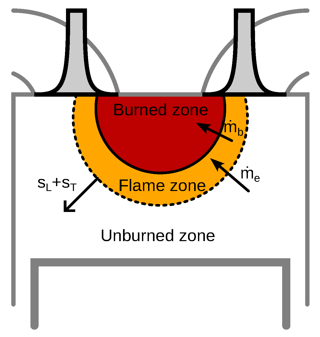
2.1.2. Combustion
2.1.3. Flame Front Area
2.1.4. Heat Release
2.1.5. Model Validation
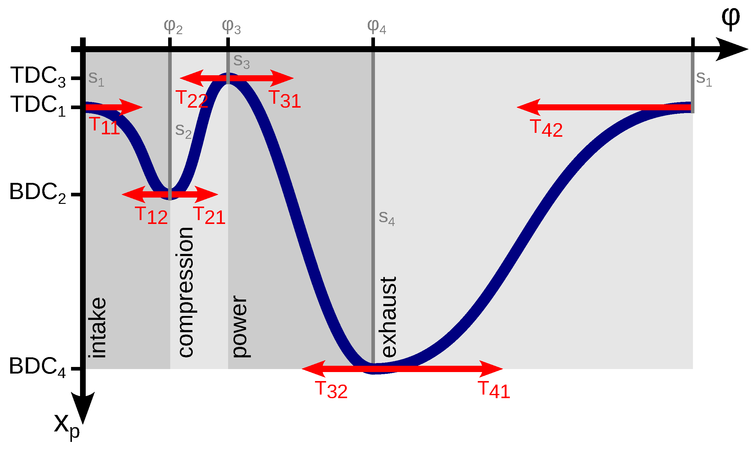
2.1.6. Piston Kinematics
2.2. Optimization and Simulation Setup
3. Results and Discussion
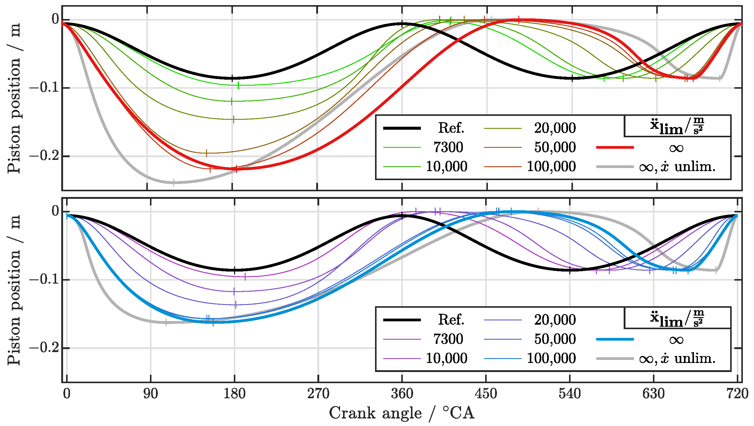
3.1. New Piston Trajectory Characteristics
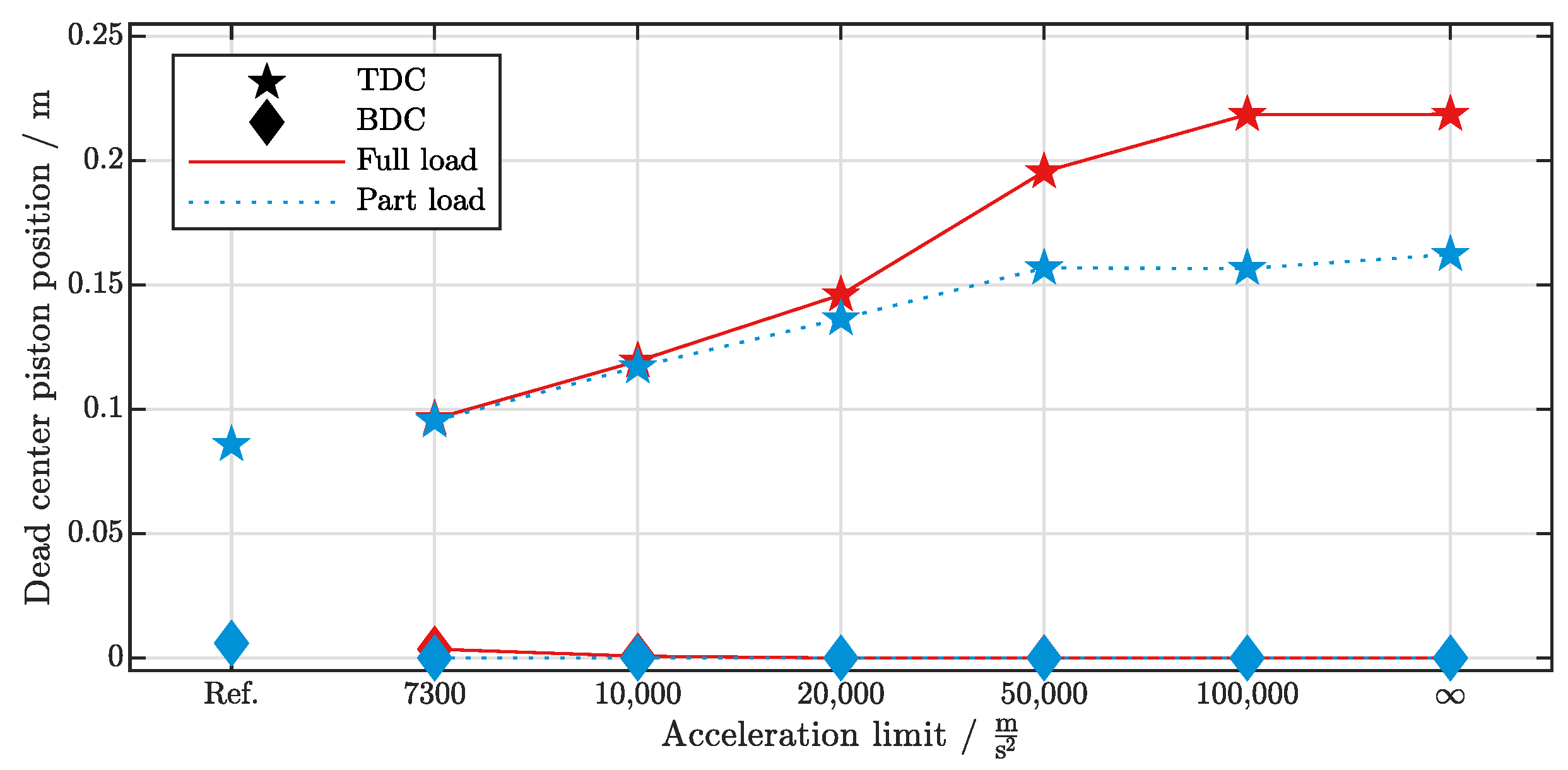
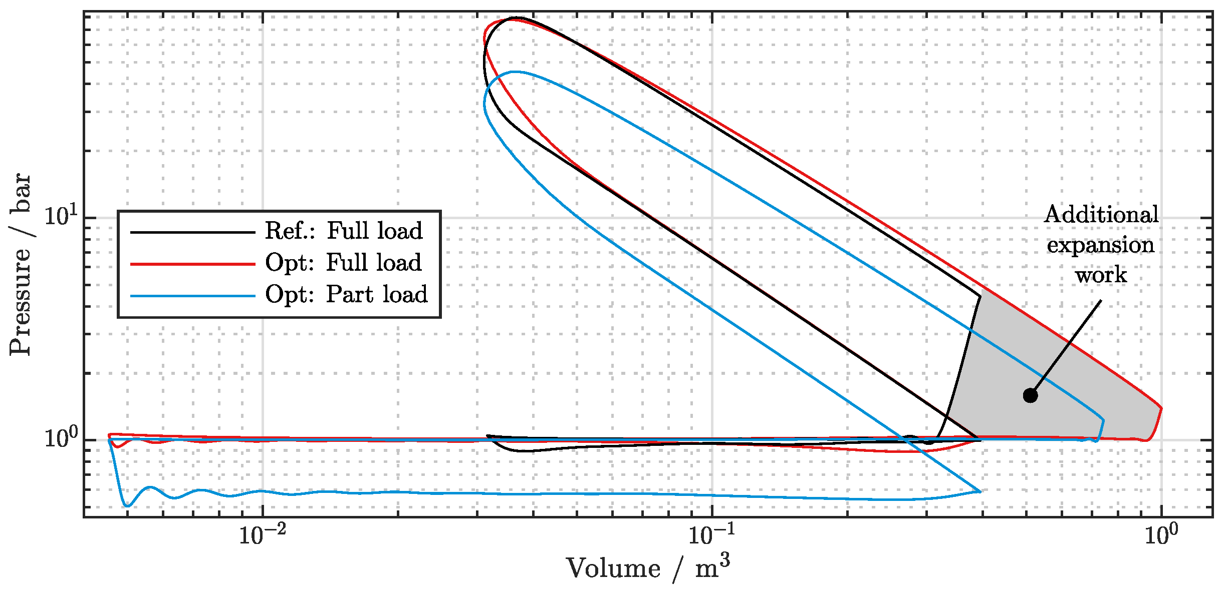
3.1.1. Expansion Ratio
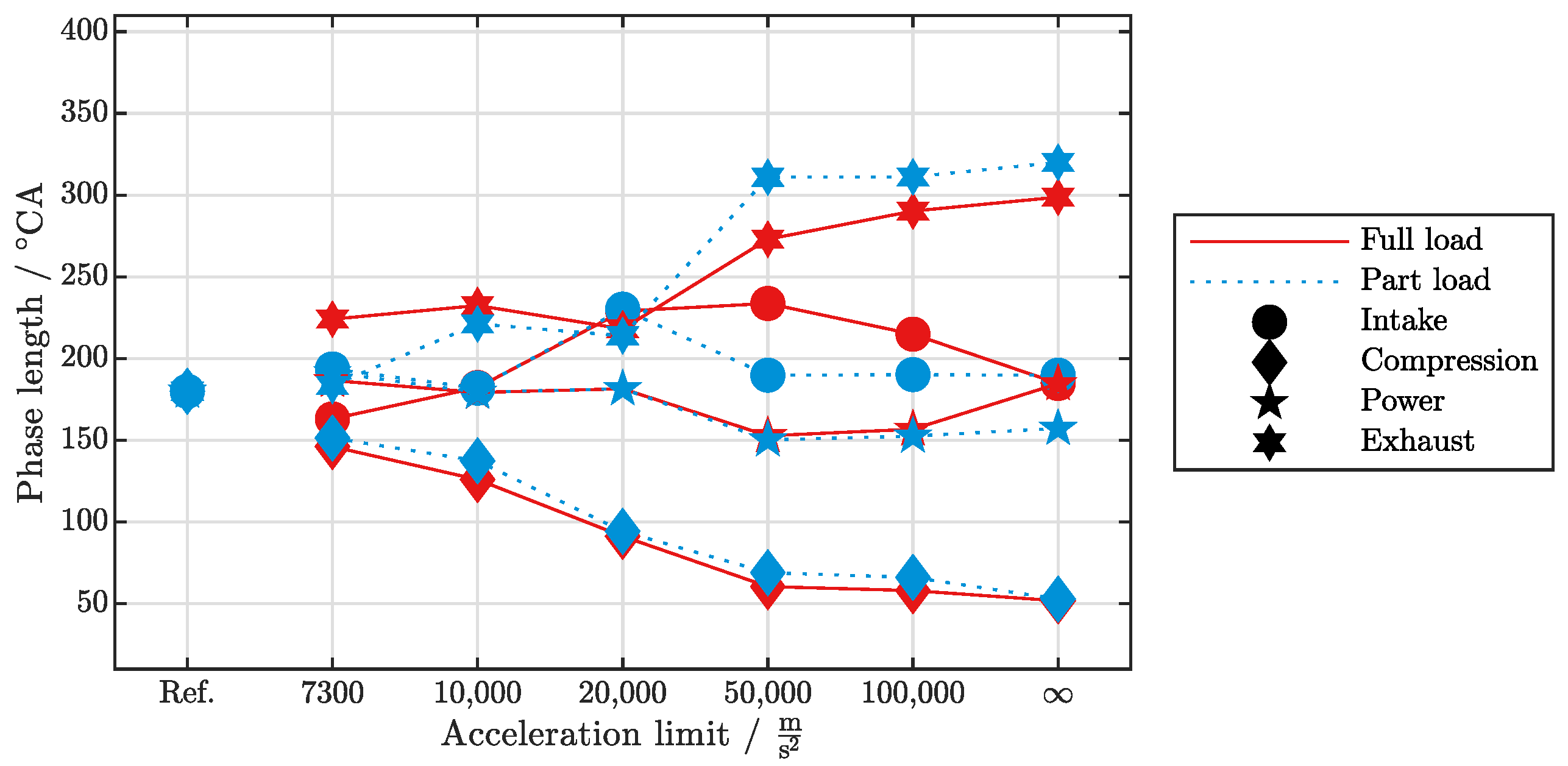
3.1.2. Stroke Timing
3.2. Analysis of Numeric Results
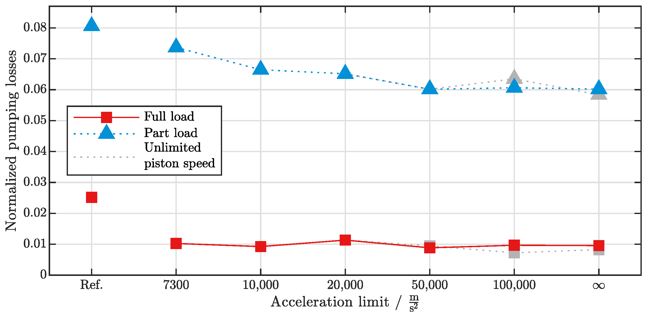
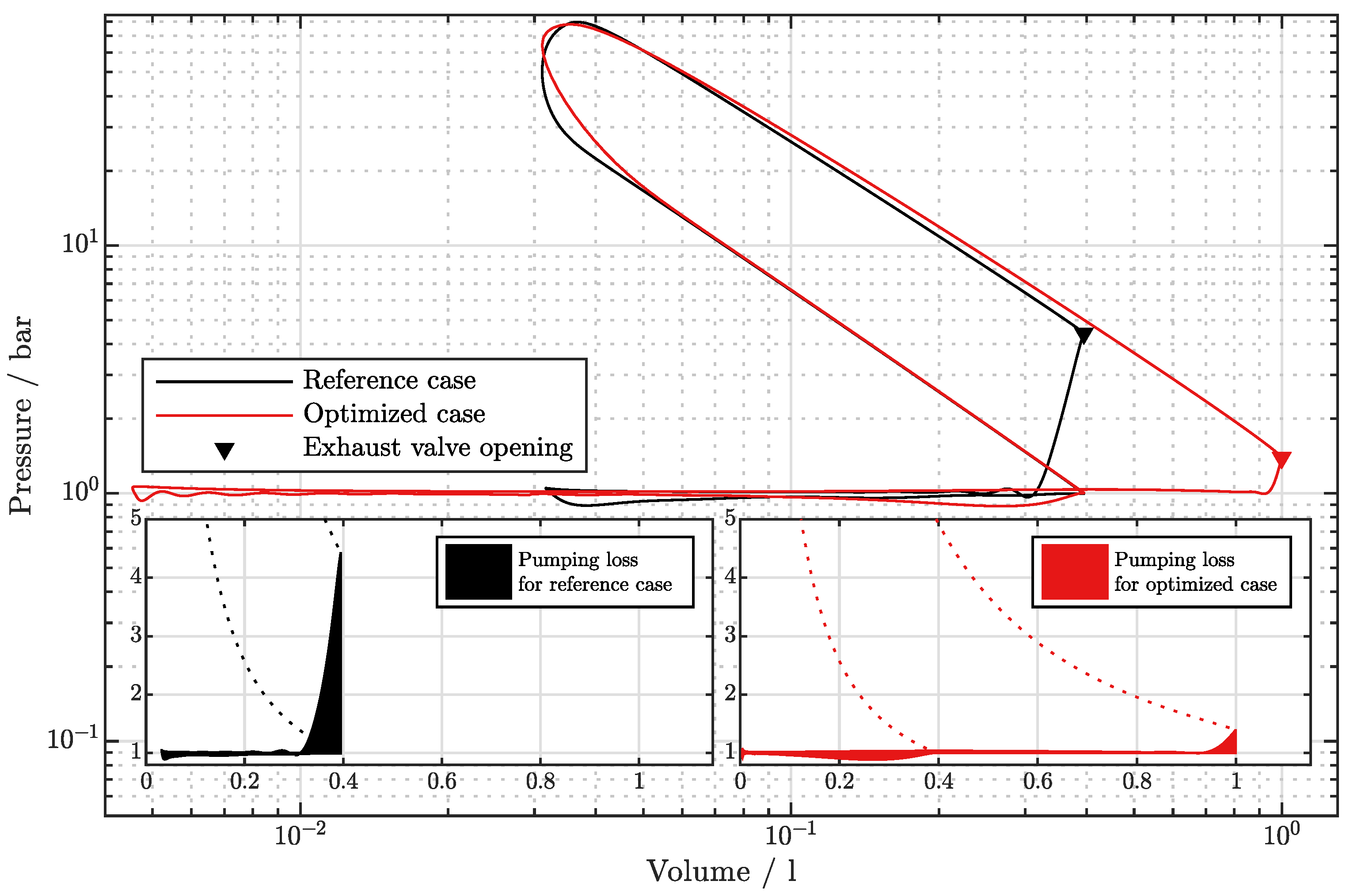
3.2.1. Pumping Losses
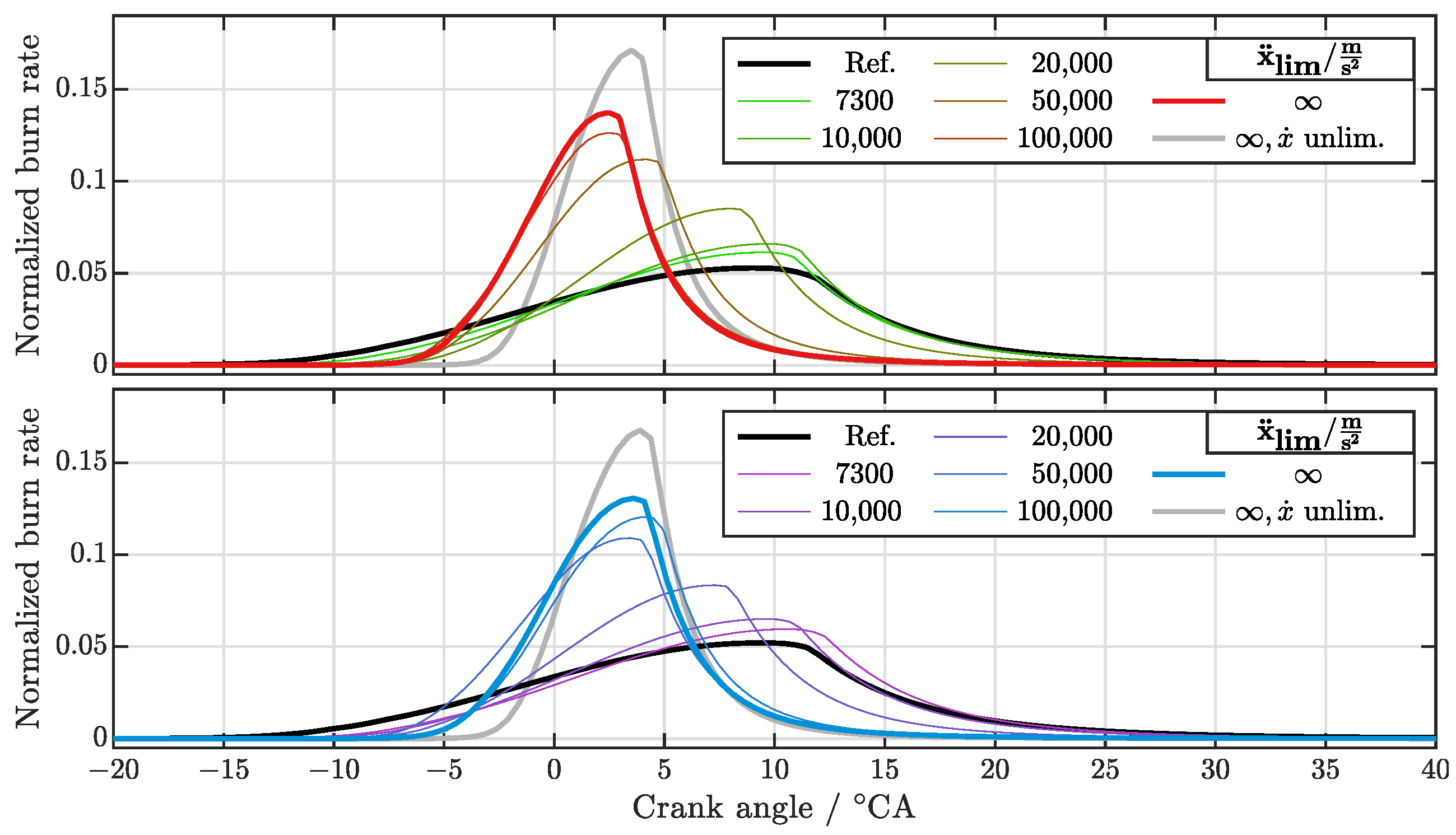
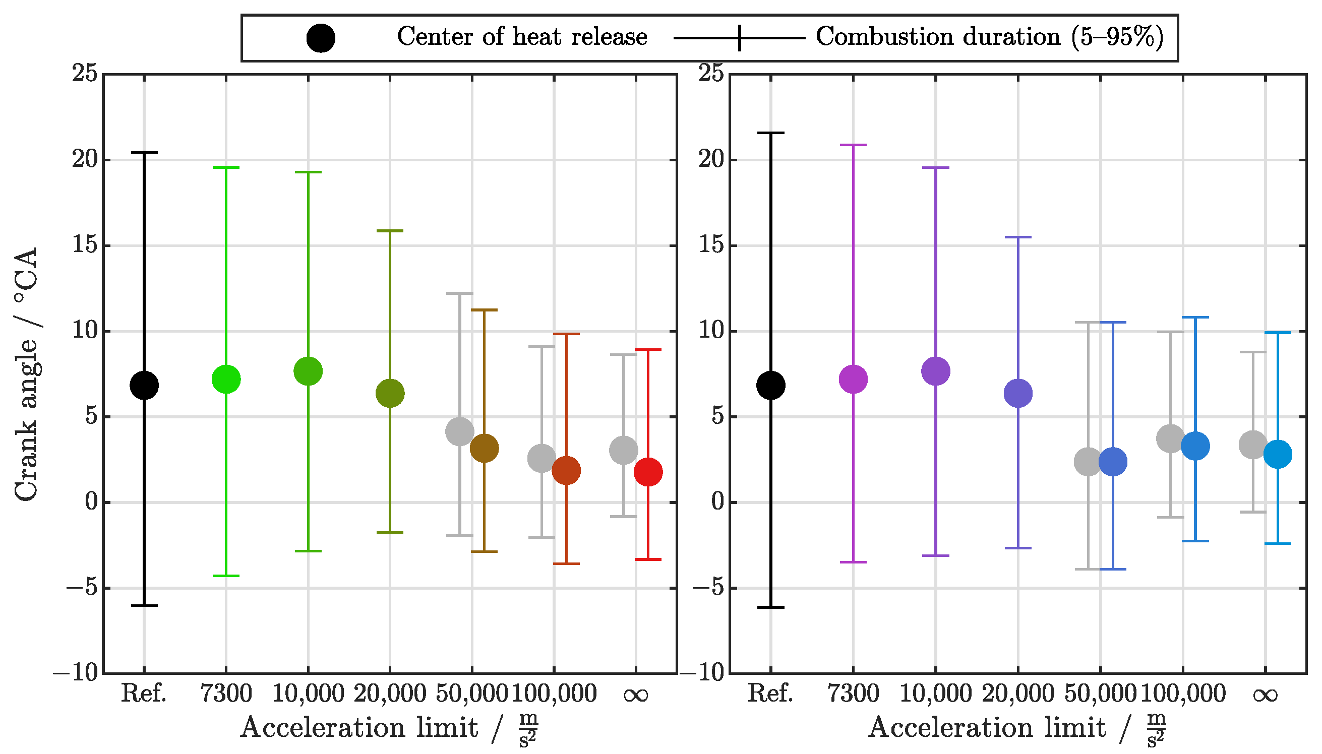
3.2.2. Heat Release
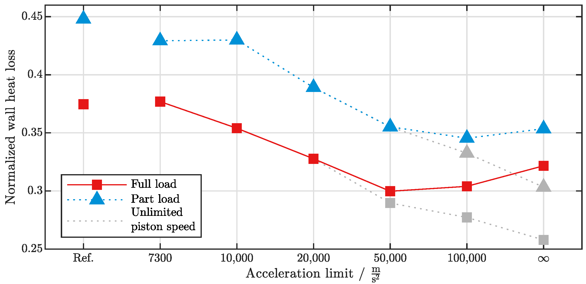
3.2.3. Wall Heat Losses
3.2.4. Trapped Air Mass
3.2.5. Piston Acceleration and Velocity
3.2.6. Part Load
4. Conclusions
Outlook
Author Contributions
Funding
Data Availability Statement
Acknowledgments
Conflicts of Interest
Abbreviations
| ACC | Active combustion chamber |
| CA | Crank angle |
| BDC | Bottom dead center |
| DI | Direct injection |
| GT | Gamma technologies |
| ICE | Internal combustion engine |
| NASA | National Aeronautics and Space Administration |
| PC | Personal computer |
| TDC | Top dead center |
| VCR | Variable compression ratio |
Appendix A

| Full Load | Part Load | |||||||||||||
|---|---|---|---|---|---|---|---|---|---|---|---|---|---|---|
| mbar | 1000 | 583 | ||||||||||||
| Ref. | 7300 | 10,000 | 20,000 | 50,000 | 100,000 | ∞ | 7300 | 10,000 | 20,000 | 50,000 | 100,000 | ∞ | ||
| °CA | 0.0 | 0.0 | 0.0 | 0.0 | 0.0 | 0.0 | 0.0 | 0.0 | 0.0 | 0.0 | 0.0 | 0.0 | 0.0 | |
| °CA | 180.0 | 186.6 | 179.3 | 181.5 | 152.8 | 156.8 | 184.6 | 191.4 | 179.5 | 181.5 | 150.3 | 152.6 | 157.3 | |
| °CA | 360.0 | 410.7 | 411.8 | 399.7 | 425.8 | 447.0 | 483.4 | 374.9 | 400.7 | 395.4 | 461.2 | 463.7 | 477.3 | |
| °CA | 540.0 | 573.8 | 594.0 | 628.7 | 659.5 | 662.0 | 668.2 | 568.6 | 582.6 | 625.7 | 651.0 | 653.9 | 667.1 | |
| °CA | 180.0 | 186.6 | 179.3 | 181.5 | 152.8 | 156.8 | 184.6 | 191.4 | 179.5 | 181.5 | 150.3 | 152.6 | 157.3 | |
| °CA | 180.0 | 224.1 | 232.5 | 218.2 | 273.0 | 290.2 | 298.8 | 183.5 | 221.2 | 213.9 | 310.9 | 311.1 | 320.0 | |
| °CA | 180.0 | 163.1 | 182.3 | 229.1 | 233.7 | 214.9 | 184.8 | 193.7 | 181.9 | 230.3 | 189.8 | 190.2 | 189.8 | |
| °CA | 180.0 | 146.2 | 126.0 | 91.3 | 60.5 | 58.0 | 51.8 | 151.4 | 137.4 | 94.3 | 69.0 | 66.1 | 52.9 | |
| mm | 5.8 | 5.8 | 5.8 | 5.8 | 5.8 | 5.8 | 5.8 | 5.8 | 5.8 | 5.8 | 5.8 | 5.8 | 5.8 | |
| mm | 85.8 | 96.2 | 119.4 | 146.1 | 195.6 | 218.5 | 218.7 | 95.4 | 117.1 | 136.5 | 156.8 | 156.7 | 162.3 | |
| mm | 6.0 | 3.6 | 0.7 | 0.0 | 0.1 | 0.0 | 0.0 | 0.0 | 0.0 | 0.0 | 0.0 | 0.0 | 0.0 | |
| mm | 85.8 | 85.8 | 85.8 | 85.8 | 85.8 | 85.8 | 85.8 | 85.8 | 85.8 | 85.8 | 85.8 | 85.8 | 85.8 | |
| °CA | 171.9 | 178.0 | 176.2 | 167.6 | 88.3 | 53.1 | 58.2 | 183.9 | 172.9 | 149.9 | 83.5 | 84.3 | 78.0 | |
| °CA | 171.9 | 185.1 | 155.3 | 89.9 | 60.6 | 53.5 | 41.4 | 170.0 | 147.0 | 93.0 | 69.6 | 35.8 | 30.4 | |
| °CA | 239.4 | 449.2 | 504.7 | 490.1 | 463.4 | 433.1 | 434.2 | 295.5 | 445.1 | 370.9 | 447.8 | 461.3 | 441.7 | |
| °CA | 239.4 | 259.1 | 274.7 | 392.1 | 245.5 | 220.9 | 329.3 | 303.7 | 272.9 | 391.5 | 312.6 | 322.3 | 330.3 | |
| °CA | 171.9 | 218.2 | 316.1 | 562.1 | 597.3 | 577.4 | 451.4 | 307.3 | 317.9 | 544.2 | 398.4 | 427.1 | 417.1 | |
| °CA | 171.9 | 222.0 | 259.9 | 273.0 | 299.2 | 297.0 | 300.7 | 218.6 | 272.2 | 266.2 | 312.4 | 313.7 | 331.2 | |
| °CA | 239.4 | 185.6 | 160.1 | 92.5 | 69.0 | 65.0 | 40.2 | 177.2 | 186.0 | 107.1 | 110.4 | 111.0 | 54.1 | |
| °CA | 239.4 | 175.3 | 234.5 | 255.6 | 259.0 | 270.1 | 254.4 | 247.1 | 250.2 | 272.1 | 257.5 | 260.6 | 256.0 | |
References
- Mozurkewich, M.; Berry, R.S. Optimal paths for thermodynamic systems: The ideal Otto cycle. J. Appl. Phys. 1982, 53, 34–42. [Google Scholar] [CrossRef]
- Huleihil, M.; Andresen, B. Optimal piston trajectories for adiabatic processes in the presence of friction. J. Appl. Phys. 2006, 100, 114914. [Google Scholar] [CrossRef] [Green Version]
- Atkinson, J. Gas Engine. Patent US367496. 1887. Available online: https://patentimages.storage.googleapis.com/f0/d5/eb/c4fc0749bb82b2/US367496.pdf (accessed on 30 August 2022).
- Merker, G.P.; Teichmann, R. Grundlagen Verbrennungsmotoren, 7th ed.; Springer Vieweg: Wiesbaden, Germany, 2014; pp. 119–121. [Google Scholar] [CrossRef]
- Ge, Y.; Chen, L.; Sun, F. Optimal path of piston motion of irreversible Otto cycle for minimum entropy generation with radiative heat transfer law. J. Energy Inst. 2012, 85, 140–149. [Google Scholar] [CrossRef]
- Lin, J.; Chang, S.; Xu, Z. Optimal motion trajectory for the four-stroke free-piston engine with irreversible Miller cycle via a Gauss pseudospectral method. J. Non-Equilib. Thermodyn. 2008, 39, 159–172. [Google Scholar] [CrossRef]
- Xu, J.; Yuan, C.; He, Y.; Wang, R. An optimization of free-piston engine generator combustion using variable piston motion. Adv. Mech. Eng. 2017, 9, 1–10. [Google Scholar] [CrossRef]
- Zhang, C.; Li, K.; Sun, Z. Modeling of piston trajectory-based HCCI combustion enabled by a free piston engine. Appl. Energy 2015, 139, 313–326. [Google Scholar] [CrossRef]
- Roberts, M. Benefits and Challenges of Variable Compression Ratio (VCR); SAE Technical Paper 2003-01-0398; SAE International: Warrendale, PA, USA, 2003. [Google Scholar]
- Asthana, S.; Bansal, S.; Jaggi, S.; Kumar, N. A Comparative Study of Recent Advancements in the Field of Variable Compression Ratio Engine Technology; SAE Technical Paper 2016-01-0669; SAE International: Warrendale, PA, USA, 2016. [Google Scholar] [CrossRef]
- Dabrowski, A.; Glogowski, M.; Kubiak, P. Improving the efficiency of four-stroke engine with use of the pneumatic energy accumulator—Simulations and examination. Int. J. Automot. Technol. 2016, 17, 581–590. [Google Scholar] [CrossRef]
- Deb, K.; Jain, H. An Evolutionary Many-Objective Optimization Algorithm Using Reference-Point-Based Nondominated Sorting Approach, Part I: Solving Problems With Box Constraints. IEEE Trans. Evol. Comput. 2014, 18, 577–601. [Google Scholar] [CrossRef]
- Gamma Technologies LLC. GT-Suite Flow Theory Manual Version 2020; Gamma Technologies LLC: Westmont, IL, USA, 2020. [Google Scholar]
- Gamma Technologies LLC. GT-Suite Engine Performance Application Manual Version 2020; Gamma Technologies LLC: Westmont, IL, USA, 2020. [Google Scholar]
- McBride, B.J.; Gordon, S.; Reno, M.A. Coefficients for Calculating Thermodynamic and Transport Properties of Individual Species. NASA Technical Memorandum; 1993. Available online: https://ntrs.nasa.gov/citations/19940013151 (accessed on 30 August 2022).
- Woschni, G. A Universally Applicable Equation for the Instantaneous Heat Transfer Coefficient in the Internal Combustion Engine. SAE Trans. 1968, 76, 3065–3083. [Google Scholar]
- Heywood, J.B. Internal Combustion Engine Fundamentals; McGraw-Hill: New York, NY, USA, 1988; ISBN 0-07-028637-X. [Google Scholar]
- Gamma Technologies LLC. GT-Suite 2020 Help Menue (Reference Manual—Flow—Engine Reference Template—Si-Turbulent Flame); Gamma Technologies LLC: Westmont, IL, USA, 2020. [Google Scholar]
- Krebs, S.; Biet, C. Predictive model of a premixed, lean hydrogen combustion for internal combustion engines. Transp. Eng. 2021, 5, 100086. [Google Scholar] [CrossRef]
- Pipenbrinck, N. Hermite Curve Interpolation. Available online: https://www.cubic.org/docs/hermite.htm (accessed on 30 August 2022).
- Worret, R. Zylinderdruckbasierte Detektion und Simulation der Klopfgrenze Mit Einem Verbesserten Thermodynamischen Ansatz. Ph.D. Thesis, University of Karlsruhe, Karlsruhe, Germany, 2002. [Google Scholar]
- The Fastest Production Audi Ever: The New AUDI R8. AUDI AG Product and Technology Communications. 2015. Available online: https://audimediacenter-a.akamaihd.net/system/production/uploaded_files/366/file/d9f72d4b92b263acccf5dcec5fce345deeb5295b/eBasisinformation_R8.pdf?1484227032 (accessed on 22 September 2022).


| Ingnition | Center of Heat Release | Burn Duration (10–90%) | Indicated Mean Effective Pressure | ||
|---|---|---|---|---|---|
| °CA | °CA | °CA | °CA | ||
| Full load | experiment | 11.347 | 19.682 | 24.282 | 10.5448 |
| simulation | 11.302 | 23.62 | 11.542 | ||
| Part load | experiment | 26.05 | 10.577 | 21.86 | 4.26 |
| simulation | 10.58 | 21.93 | 6.28 |
| Reference | Optimized | |||||||
|---|---|---|---|---|---|---|---|---|
| Piston acc. limit | 7300 | 10,000 | 20,000 | 50,000 | 100,000 | ∞ | ||
| Max. piston acc. | 7255 | 7288 | 9998 | 19,966 | 49,906 | 65,859 | 69,479 | |
| Max. piston speed | 15.2 | 19.9 | 25.34 | 35.77 | 43.98 | 43.94 | 43.96 | |
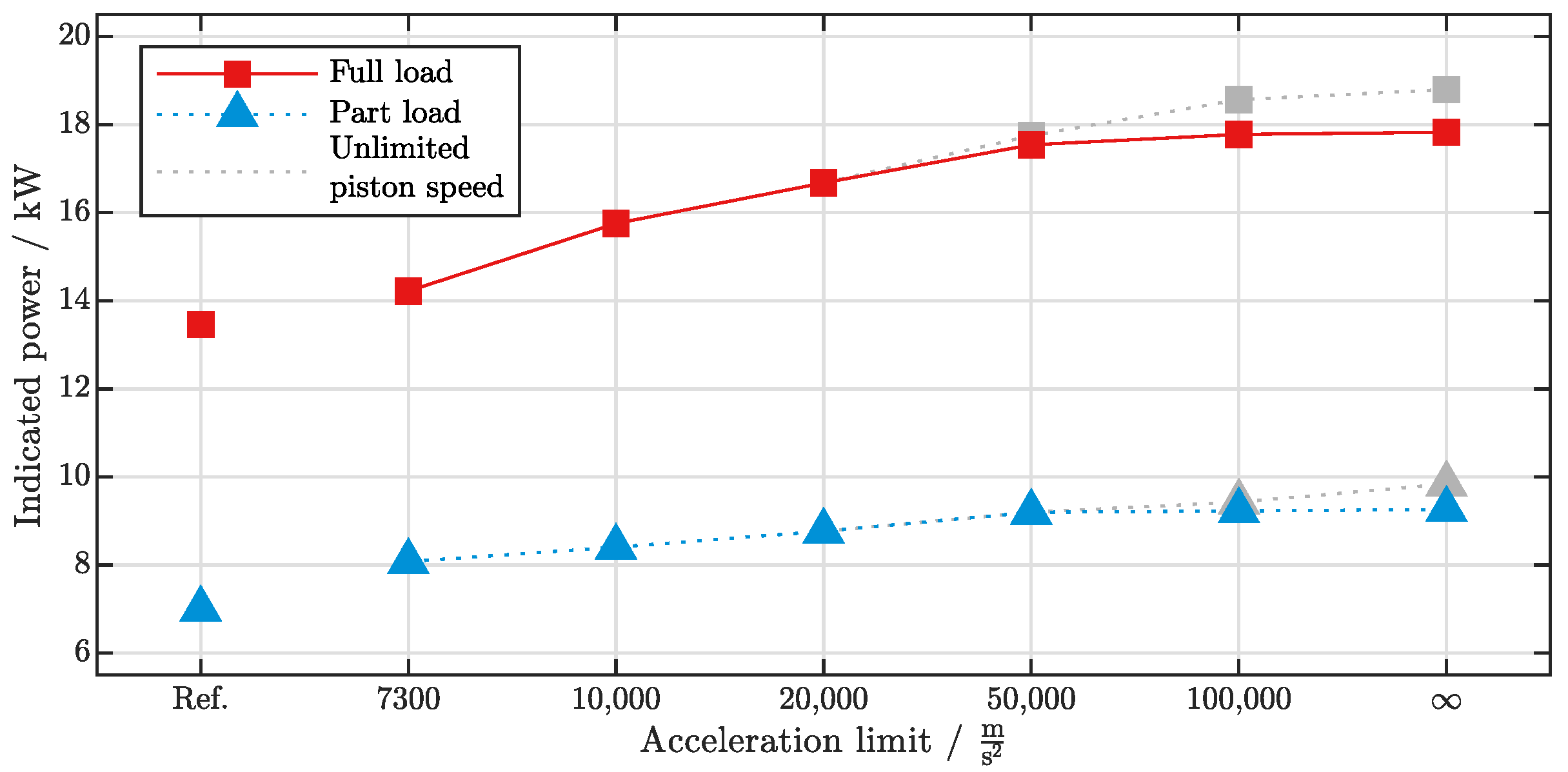
| Indicated power | kW | 13.5 | 14.2 | 15.8 | 16.7 | 17.5 | 17.8 | 17.8 |
| Indicated efficiency | % | 42.5 | 44.5 | 46.8 | 49.0 | 51.4 | 51.8 | 51.9 |
Publisher’s Note: MDPI stays neutral with regard to jurisdictional claims in published maps and institutional affiliations. |
© 2022 by the authors. Licensee MDPI, Basel, Switzerland. This article is an open access article distributed under the terms and conditions of the Creative Commons Attribution (CC BY) license (https://creativecommons.org/licenses/by/4.0/).
Share and Cite
Biet, C.; Krebs, S. Determination of Optimal Piston Trajectories for High Efficiency 4-Stroke Cycles by Using Predictive Combustion Modeling. Thermo 2022, 2, 352-370. https://doi.org/10.3390/thermo2040024
Biet C, Krebs S. Determination of Optimal Piston Trajectories for High Efficiency 4-Stroke Cycles by Using Predictive Combustion Modeling. Thermo. 2022; 2(4):352-370. https://doi.org/10.3390/thermo2040024
Chicago/Turabian StyleBiet, Clemens, and Sören Krebs. 2022. "Determination of Optimal Piston Trajectories for High Efficiency 4-Stroke Cycles by Using Predictive Combustion Modeling" Thermo 2, no. 4: 352-370. https://doi.org/10.3390/thermo2040024