Sensing Technology Survey for Obstacle Detection in Vegetation


Abstract
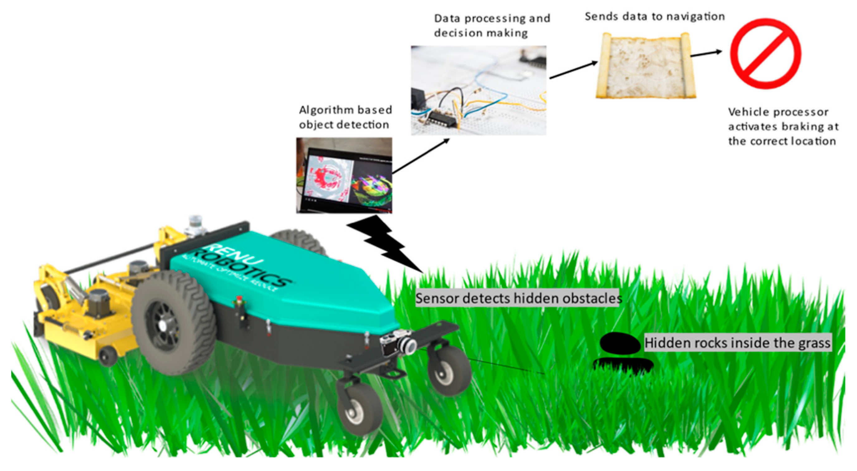
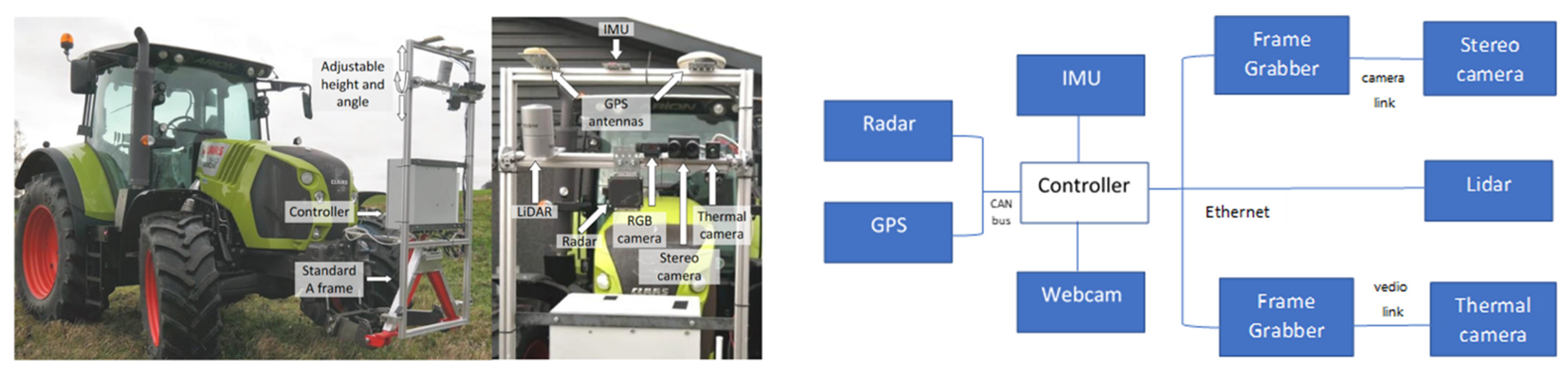
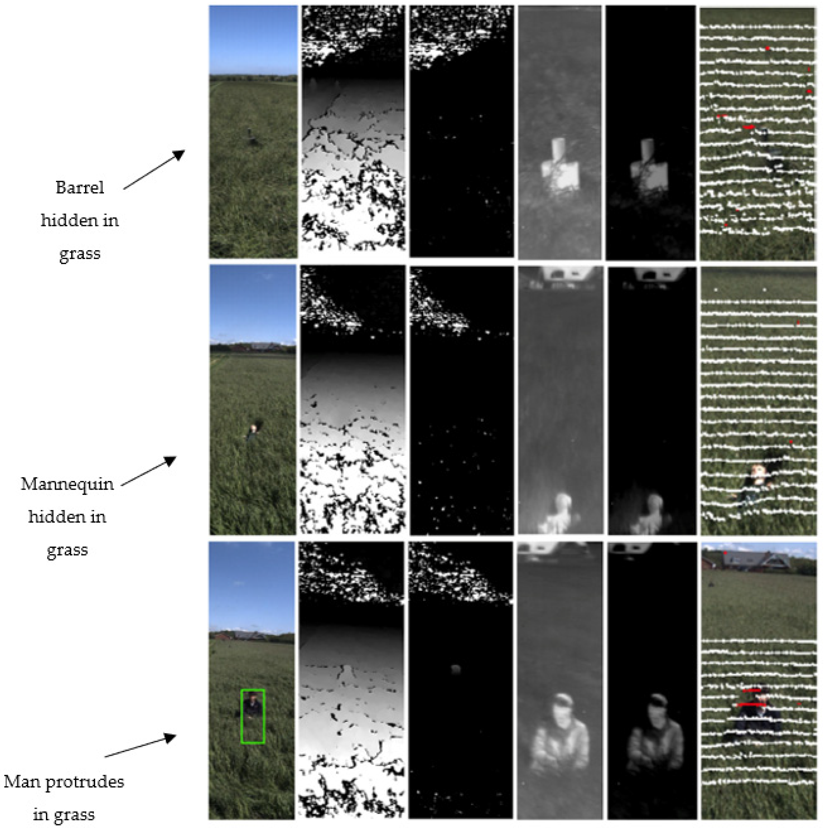
:1. Introduction
2. Sensors and the Electromagnetic Spectrum
2.1. Passive Sensors
2.1.1. Stereo Cameras
2.1.2. RGB Cameras
2.1.3. Thermal Infrared Cameras
2.1.4. Hyperspectral Sensing
2.2. Active Sensors
2.2.1. LiDAR Sensors
2.2.2. Radar
3. Comparison of Sensors
4. Fusion of Sensors Applications
4.1. RGB and Infrared Camera
4.2. Radar and Stereo Camera
4.3. LiDAR and Camera
4.4. LiDAR and Radar
4.5. Multimodal Sensors
5. Conclusions and Recommendations
Author Contributions
Funding
Acknowledgments
Conflicts of Interest
References
- Nguyen, D.-V. Vegetation Detection and Terrain Classification for Autonomous Navigation. 2013. Available online: https://www.researchgate.net/publication/265160356_Vegetation_Detection_and_Terrain_Classification_for_Autonomous_Navigation (accessed on 6 September 2021).
- Rasmussen, S.; Schrøder, A.; Mathiesen, R.; Nielsen, J.; Pertoldi, C.; Macdonald, D. Wildlife Conservation at a Garden Level: The Effect of Robotic Lawn Mowers on European Hedgehogs (Erinaceus europaeus). Animals 2021, 11, 1191. [Google Scholar] [CrossRef]
- Jinru, X.; Su, B. Significant Remote Sensing Vegetation Indices: A Review of Developments and Applications. J. Sens. 2017, 2017, 1353691. [Google Scholar]
- Zhu, L.; Holden, J.; Gonder, J. Trajectory Segmentation Map-Matching Approach for Large-Scale, High-Resolution GPS Data. Transp. Res. Rec. J. Transp. Res. Board 2017, 2645, 67–75. [Google Scholar] [CrossRef]
- Zhu, L.; Gonder, J.; Lin, L. Prediction of Individual Social-Demographic Role Based on Travel Behavior Variability Using Long-Term GPS Data. J. Adv. Transp. 2017, 2017, 7290248. [Google Scholar] [CrossRef] [Green Version]
- Laugraud, B.; Piérard, S.; van Droogenbroeck, M. Labgen-p-semantic: A first step for leveraging semantic segmentation in background generation. J. Imaging 2018, 4, 86. [Google Scholar] [CrossRef] [Green Version]
- Zeng, D.; Chen, X.; Zhu, M.; Goesele, M.; Kuijper, A. Background Subtraction with Real-Time Semantic Segmentation. IEEE Access 2019, 7, 153869–153884. [Google Scholar] [CrossRef]
- Zaarane, A.; Slimani, I.; Al Okaishi, W.; Atouf, I.; Hamdoun, A. Distance measurement system for autonomous vehicles using stereo camera. Array 2020, 5, 100016. [Google Scholar] [CrossRef]
- Aggarwal, S. Photogrammetry and Remote Sensing Division Indian Institute of Remote Sensing, Dehra Dun. Available online: https://www.preventionweb.net/files/1682_9970.pdf#page=28 (accessed on 6 September 2021).
- Salman, Y.D.; Ku-Mahamud, K.R.; Kamioka, E. Distance measurement for self-driving cars using stereo camera. In Proceedings of the International Conference on Computing and Informatics, Kuala Lumpur, Malaysia, 5–27 April 2017. [Google Scholar]
- Zhang, Z.; Han, Y.; Zhou, Y.; Dai, M. A novel absolute localization estimation of a target with monocular vision. Optik 2013, 124, 1218–1223. [Google Scholar] [CrossRef]
- Seitz, S.M.; Curless, B.; Diebel, J.; Scharstein, D.; Szeliski, R. A Comparison and Evaluation of Multi-View Stereo Reconstruction Algorithms. In Proceedings of the 2006 IEEE Computer Society Conference on Computer Vision and Pattern Recognition, New York, NY, USA, 17–22 June 2006. [Google Scholar]
- Bailey, T.; Durrant-Whyte, H. Simultaneous localization and mapping (SLAM): Part II. IEEE Robot. Autom. Mag. 2006, 13, 108–117. [Google Scholar] [CrossRef] [Green Version]
- Choset, H.; Nagatani, K. Topological simultaneous localization and mapping (SLAM): Toward exact localization without explicit localization. IEEE Trans. Robot. Autom. 2001, 17, 125–137. [Google Scholar] [CrossRef] [Green Version]
- Schonberger, J.L.; Frahm, J.M. Structure-from-motion revisited. In Proceedings of the IEEE Conference on Computer Vision and Pattern Recognition, Las Vegas, NV, USA, 26 June–1 July 2016. [Google Scholar]
- Özyeşil, O.; Voroninski, V.; Basri, R.; Singer, A. A survey of structure from motion. Acta Numer. 2017, 26, 305–364. [Google Scholar] [CrossRef]
- Cadena, C.; Carlone, L.; Carrillo, H.; Latif, Y.; Scaramuzza, D.; Neira, J.; Reid, I.; Leonard, J.J. Past, Present, and Future of Simultaneous Localization and Mapping: Toward the Robust-Perception Age. IEEE Trans. Robot. 2016, 32, 1309–1332. [Google Scholar] [CrossRef] [Green Version]
- Ulaby, F.T.; Wilson, E.A. Microwave attenuation properties of vegetation canopies. IEEE Trans. Geosci. Remote. Sens. 1985, GE-23, 746–753. [Google Scholar] [CrossRef]
- Rankin, A.; Huertas, A.; Matthies, L.; Bajracharya, M.; Assad, C.; Brennan, S.; Bellutta, P.; Sherwin, G.W. Unmanned ground vehicle perception using thermal infrared cameras. In Proceedings of the Unmanned Systems Technology XIII. International Society for Optics and Photonics, SPIE Defense, Security and Sensing, Orlando, FL, USA, 25–29 April 2011. [Google Scholar]
- Gomez, R.B. Hyperspectral imaging: A useful technology for transportation analysis. Opt. Eng. 2002, 41, 2137–2143. [Google Scholar] [CrossRef]
- Hyperspectral Imaging and Obstacle Detection for Robotics Navigation. Available online: https://apps.dtic.mil/sti/pdfs/ADA486436.pdf (accessed on 12 April 2021).
- Killinger, D. Lidar (Light Detection and Ranging); Elsevier: Amsterdam, The Netherlands, 2014; pp. 292–312. [Google Scholar] [CrossRef]
- Zhao, J.; Xu, H.; Liu, H.; Wu, J.; Zheng, Y.; Wu, D. Detection and tracking of pedestrians and vehicles using roadside LiDAR sensors. Transp. Res. Part C Emerg. Technol. 2019, 100, 68–87. [Google Scholar] [CrossRef]
- Wu, J.; Xu, H.; Zheng, Y.; Tian, Z. A novel method of vehicle-pedestrian near-crash identification with roadside LiDAR data. Accid. Anal. Prev. 2018, 121, 238–249. [Google Scholar] [CrossRef]
- Wu, J.; Xu, H.; Zheng, J. Automatic background filtering and lane identification with roadside LiDAR data. In Proceedings of the 2017 IEEE 20th International Conference on Intelligent Transportation Systems (ITSC), Yokohama, Japan, 16 October 2017. [Google Scholar]
- Kragh, M.F. Lidar-Based Obstacle Detection and Recognition for Autonomous Agricultural Vehicles; AU Library Scholarly Publishing Services: Aarhus, Denmark, 2018. [Google Scholar] [CrossRef]
- Wang, P.; Chen, P.; Yuan, Y.; Liu, D.; Huang, Z.; Hou, X.; Cottrell, G. Understanding convolution for semantic segmentation. In Proceedings of the 2018 IEEE Winter Conference on Applications of Computer Vision (WACV), Lake Tahoe, NV, USA, 12–15 March 2018. [Google Scholar]
- Larson, J.; Trivedi, M. Lidar based off-road negative obstacle detection and analysis. In Proceedings of the 2011 14th International IEEE Conference on Intelligent Transportation Systems (ITSC), Washington, DC, USA, 5–7 October 2011. [Google Scholar]
- Manjunath, A.; Liu, Y.; Henriques, B.; Engstle, A. Radar based object detection and tracking for autonomous driving. In Proceedings of the in 2018 IEEE MTT-S International Conference on Microwaves for Intelligent Mobility (ICMIM), Munich, Germany, 15–17 April 2018. [Google Scholar]
- Matthies, L.; Bergh, C.; Castano, A.; Macedo, J.; Manduchi, R. Obstacle Detection in Foliage with Ladar and Radar. In Proceedings of the Eleventh International Symposium Robotics Research, Siena, Italy, 19–22 October 2003; Springer: Berlin/Heidelberg, Germany, 2005; Volume 15, pp. 291–300. [Google Scholar] [CrossRef] [Green Version]
- Richards, J. The Use of Multiple-Polarization Data in Foliage Penetrating (FOPEN) Synthetic Aperture Radar (SAR) Applications; SAND Report; Sandia National Laboratories: Albuquerque, NW, USA; Livermore, CA, USA, 2002.
- Reina, G.; Underwood, J.; Brooker, G.; Durrant-Whyte, H. Radar-based perception for autonomous outdoor vehicles. J. Field Robot. 2011, 28, 894–913. [Google Scholar] [CrossRef]
- Jing, X.; Du, Z.C.; Li, F. Obstacle detection by Doppler frequency shift. Electron. Sci. Technol. 2013, 26, 57–60. [Google Scholar]
- Gusland, D.; Torvik, B.; Finden, E.; Gulbrandsen, F.; Smestad, R. Imaging radar for navigation and surveillance on an autonomous unmanned ground vehicle capable of detecting obstacles obscured by vegetation. In Proceedings of the 2019 IEEE Radar Conference (RadarConf), Boston, MA, USA, 22–26 April 2019. [Google Scholar]
- Khan, M.J.; Khan, H.S.; Yousaf, A.; Khurshid, K.; Abbas, A. Modern Trends in Hyperspectral Image Analysis: A Review; IEEE: New York, NY, USA, 2018; pp. 14118–14129. [Google Scholar]
- Adão, T.; Hruška, J.; Pádua, L.; Bessa, J.; Peres, E.; Morais, R.; Sousa, J.J. Hyperspectral Imaging: A Review on UAV-Based Sensors, Data Processing and Applications for Agriculture and Forestry. Remote Sens. 2017, 9, 1110. [Google Scholar] [CrossRef] [Green Version]
- Govender, M.; Chetty, K.; Bulcock, H. A review of hyperspectral remote sensing and its application in vegetation and water resource studies. J. Water S. Afr. 2007, 33, 145–151. [Google Scholar] [CrossRef] [Green Version]
- Honkavaara, E.; Saari, H.; Kaivosoja, J.; Pölönen, I.; Hakala, T.; Litkey, P.; Mäkynen, J.; Pesonen, L. Processing and Assessment of Spectrometric, Stereoscopic Imagery Collected Using a Lightweight UAV Spectral Camera for Precision Agriculture. Remote Sens. 2013, 5, 5006–5039. [Google Scholar] [CrossRef] [Green Version]
- Wilcox, C.C.; Montes, M.; Yetzbacher, M.; Edelberg, J.; Schlupf, J. Micro-and Nanotechnology Sensors, Systems, and Applications X. In Proceedings of the SPIE Defence and Security, Orlando, FL, USA, 15 April 2018. [Google Scholar]
- Landgrebe, D. Information Extraction Principles and Methods for Multispectral and Hyperspectral Image Data. In Information Processing for Remote Sensing; World Scientific Publishing: Singapore, 1999. [Google Scholar]
- Stuart, M.B.; Mcgonigle, A.J.S.; Willmott, J.R. Hyperspectral Imaging in Environmental Monitoring: A Review of Recent Developments and Technological Advances in Compact Field Deployable Systems. Sensors 2019, 19, 3071. [Google Scholar] [CrossRef] [PubMed] [Green Version]
- Kragh, M.; Underwood, J. Multimodal obstacle detection in unstructured environments with conditional random fields. J. Field Robot. 2019, 37, 53–72. [Google Scholar] [CrossRef] [Green Version]
- Fu, C.; Mertz, C.; Dolan, J.M. LIDAR and Monocular Camera Fusion: On-road Depth Completion for Autonomous Driving. In Proceedings of the 2019 IEEE Intelligent Transportation Systems Conference (ITSC), Auckland, New Zealand, 27–30 October 2019; pp. 273–278. [Google Scholar] [CrossRef]
- Zhang, Z. Microsoft Kinect Sensor and Its Effect. IEEE Multimed. 2012, 19, 4–10. [Google Scholar] [CrossRef] [Green Version]
- Hu, J.-W. A survey on multi-sensor fusion based obstacle detection for intelligent ground vehicles in off-road environments. Front. Inf. Technol. Electron. Eng. 2020, 21, 675–692. [Google Scholar] [CrossRef]
- Nissimov, S.; Goldberger, J.; Alchanatis, V. Obstacle detection in a greenhouse environment using the Kinect sensor. Comput. Electron. Agric. 2015, 113, 104–115. [Google Scholar] [CrossRef]
- Reina, G.; Milella, A.; Rouveure, R. Traversability analysis for off-road vehicles using stereo and radar data. In Proceedings of the 2015 IEEE International Conference on Industrial Technology (ICIT), Seville, Spain, 17–19 March 2015; pp. 540–546. [Google Scholar] [CrossRef]
- Jha, H.; Lodhi, V.; Chakravarty, D. Object Detection and Identification Using Vision and Radar Data Fusion System for Ground-Based Navigation. In Proceedings of the 2019 6th International Conference on Signal Processing and Integrated Networks (SPIN), Noida, India, 7–8 March 2019; pp. 590–593. [Google Scholar] [CrossRef]
- Zhao, L.; Li, S. Object detection algorithm based on improved YOLOv3. Electronics 2020, 9, 537. [Google Scholar] [CrossRef] [Green Version]
- Tseng, H.; Chang, P.C.; Andrew, G.; Jurafsky, D.; Manning, C.D. A conditional random field word segmenter for sighan bakeoff 2005. In Proceedings of the Fourth SIGHAN Workshop on Chinese Language Processing, Jeju Island, Korea, 14–15 October 2005. [Google Scholar]
- Premebida, C.; Nunes, U.J.C. Fusing LIDAR, camera and semantic information: A context-based approach for pedestrian detection. Int. J. Robot. Res. 2013, 32, 371–384. [Google Scholar] [CrossRef]
- García, F.; Garcia, J.; Ponz, A.; de la Escalera, A.; Armingol, J.M. Context aided pedestrian detection for danger estimation based on laser scanner and computer vision. Expert Syst. Appl. 2014, 41, 6646–6661. [Google Scholar] [CrossRef] [Green Version]
- Zhao, G.; Xiao, X.; Yuan, J.; Ng, G.W. Fusion of 3D-LIDAR and camera data for scene parsing. J. Vis. Commun. Image Represent. 2014, 25, 65–183. [Google Scholar] [CrossRef]
- Rubaiyat, A.H.M.; Fallah, Y.; Li, X.; Bansal, G.; Infotechnology, T. Multi-sensor Data Fusion for Vehicle Detection in Autonomous Vehicle Applications. Electron. Imaging 2018, 2018, 257-1–257-6. [Google Scholar] [CrossRef]
- Starr, J.W.; Lattimer, B.Y. Evidential Sensor Fusion of Long-Wavelength Infrared Stereo Vision and 3D-LIDAR for Rangefinding in Fire Environments. Fire Technol. 2017, 53, 1961–1983. [Google Scholar] [CrossRef]
- Shafer, G. Dempster-shafer theory. Encycl. Artif. Intell. 1992, 1, 330–331. [Google Scholar]
- Zhang, J.; Siritanawan, P.; Yue, Y.; Yang, C.; Wen, M.; Wang, D. A Two-step Method for Extrinsic Calibration between a Sparse 3D LiDAR and a Thermal Camera. In Proceedings of the 2018 15th International Conference on Control, Automation, Robotics and Vision (ICARCV), Singapore, 18–21 November 2018; pp. 1039–1044. [Google Scholar] [CrossRef]
- Yamauchi, B. Daredevil: Ultra-wideband radar sensing for small UGVs. In Proceedings of the Unmanned Systems Technology IX. International Society for Optics and Photonics, Orlando, FL, USA, 2 May 2007. [Google Scholar]
- Kwon, S.K. A Novel Human Detection Scheme and Occlusion Reasoning using LIDAR-RADAR Sensor Fusion. Master’s Thesis, University DGIST, Daegu, Korea, February 2017; p. 57. [Google Scholar]


| Sensor | Performance Affected by Weather | Performance Affected by Illumination | Resolution | Range | Typical Algorithms | Camouflage Detection | Cost | Depth Sensation |
|---|---|---|---|---|---|---|---|---|
| RGB Camera | Yes | Yes | Dense | Medium | Convolutional neural network to obtain semantic labels | No | Low | No |
| Stereo Camera | Yes | Yes | Dense | Medium | Stereovision algorithm | Yes | Medium | Yes |
| Thermal Camera | Yes | No | Dense | Medium | Off-the-shelf algorithms for terrain classification, tree trunk detection, and water detection | Yes | Medium | No |
| Hyperspectral sensing | Yes | Yes | Dense | Medium | Kernel-based image processing algorithm | Yes | Medium | No |
| LiDAR | No | No | Sparse | Long | Point cloud classification with deep learning | Yes | High | Yes |
| Radar | No | No | Highly Sparse | Medium | Deep learning and conventional methods | Yes | Medium | Yes |
| Sensor Fusion | Algorithm and Software | Applications | Potential Research and Review |
|---|---|---|---|
| RGB and infrared camera (Kinect sensor) | LBP texture analysis | Greenhouse robotic application | Cost-effective sensor suitable for dark environments rather than bright (sunlight) environments |
| Radar and stereo camera | Stereoscopic 3D information using sub-cloud region; YOLOv3 algorithm | Visible environment for stereovision and range measurement | Good object detection and location tracking fusion but needs experimentation for hidden objects and negative obstacles |
| LiDAR and camera | Semantic segmentation; CRF; CNN | Terrain classification, environment sensing, vehicle and pedestrian detection | Suitable for terrain classification and surrounding sensing at the cost of computational complexity. Needs experimentation for hidden obstacles |
| Thermal camera and LiDAR | Fusion method (Dempster–Shafer theory [59]) | Low visibility environment | Potential research and experimentation needed for detecting and sensing objects |
| LiDAR and radar | Fusion method, Point cloud classification | Sparse vegetation, partially hidden objects | Good identification of sparse vegetation but lacks in sensing dense data. Needs work in geometric identification of objects |
Publisher’s Note: MDPI stays neutral with regard to jurisdictional claims in published maps and institutional affiliations. |
© 2021 by the authors. Licensee MDPI, Basel, Switzerland. This article is an open access article distributed under the terms and conditions of the Creative Commons Attribution (CC BY) license (https://creativecommons.org/licenses/by/4.0/).
Share and Cite
Lohar, S.; Zhu, L.; Young, S.; Graf, P.; Blanton, M. Sensing Technology Survey for Obstacle Detection in Vegetation. Future Transp. 2021, 1, 672-685. https://doi.org/10.3390/futuretransp1030036
Lohar S, Zhu L, Young S, Graf P, Blanton M. Sensing Technology Survey for Obstacle Detection in Vegetation. Future Transportation. 2021; 1(3):672-685. https://doi.org/10.3390/futuretransp1030036
Chicago/Turabian StyleLohar, Shreya, Lei Zhu, Stanley Young, Peter Graf, and Michael Blanton. 2021. "Sensing Technology Survey for Obstacle Detection in Vegetation" Future Transportation 1, no. 3: 672-685. https://doi.org/10.3390/futuretransp1030036
APA StyleLohar, S., Zhu, L., Young, S., Graf, P., & Blanton, M. (2021). Sensing Technology Survey for Obstacle Detection in Vegetation. Future Transportation, 1(3), 672-685. https://doi.org/10.3390/futuretransp1030036