Article

Evaluation of the Influence of Lorentz Forces on the Natural Frequencies of a Dual-Microcantilever Sensor for Ultralow Mass Detection

1
Department of Theory of Mechanisms and Machines, Faculty of Industrial Technology, Technical University of Sofia, 1797 Sofia, Bulgaria
2
Department of Manufacturing Technology and Systems, Faculty of Industrial Technology, Technical University of Sofia, 1797 Sofia, Bulgaria
3
AMG Technology Ltd., Microelectronica Industrial Zone, 2140 Botevgrad, Bulgaria
4
Department of Electronics, Faculty of Electronic Engineering and Technologies, Technical University of Sofia, 1797 Sofia, Bulgaria
*
Author to whom correspondence should be addressed.
Micro 2024, 4(4), 572-584; https://doi.org/10.3390/micro4040035
Submission received: 27 August 2024 / Revised: 6 October 2024 / Accepted: 10 October 2024 / Published: 12 October 2024

Abstract

:
In this paper, the impact of Lorentz forces and temperature on the natural frequencies of a piezoresistive sensor composed of two microcantilevers with integrated U-shaped thin-film aluminum heaters are investigated. Two types of experiments were performed. In the first, the sensor was placed in a magnetic field so that the current flowing in the heater, in addition to raising the temperature, produced Lorentz forces, inducing normal stresses in the plane of one of the microcantilevers. In the second, which were conducted without magnetic fields, only the temperature variation of the natural frequency was left. In processing of the results, the thermal variations were subtracted from the variations due to both Lorentz forces and temperature in the natural frequency, resulting in the influence of the Lorentz forces only. Theoretical relations for the Lorentz frequency offsets were derived. An indirect method of estimating the natural frequency of one of the cantilevers, through a particular cusp point in the amplitude–frequency response of the sensor, was used in the investigations. The findings show that for thin microcantilevers with silicon masses on the order of 4 × 10⁻⁷ g and currents of 25 µA, thermal eigenfrequency variations are dominant. The results may have applications in the design of similar microsensors with vibrational action.

1. Introduction

The wide variety of sensors and actuators in microelectromechanical systems (MEMSs) based on Lorentz forces possess compact design, wide measurement range, low power consumption, and high sensitivity [1,2]. Common components in the design of MEMSs with Lorentz forces consist of a vibrating elastic element with an integrated conductor along which a direct or oscillating current flows in the vicinity of an external magnetic field. The current in the conductor creates a magnetic field that interacts with the external magnetic field via the Lorentz force, known from physics [3,4].
The application areas of MEMS sensors and actuators with Lorentz forces are diverse and multidisciplinary. For example, Basha et al. developed a microcantilever sensor that created a Lorentz force field for the study of magnetothermofluidic electroconductive flow [5]. A structure of bent beams was used for a microactuator with large displacement and low driving voltage [6]. In MEMSs, one of the most popular applications of Lorentz forces is in magnetometers, which measure magnetic flux [7,8,9]. This type of sensor is cheap and reliable, has high magnetic flux density, can be used without contact for indirect measurements of mechanical quantities, and is applicable to low values of magnetic fields, including all three axes in space [10,11,12].
In atomic force microscopes (AFMs), one option for exciting vibrations in the scanning microcantilever is Lorentz forces. This is achieved by an external permanent magnetic field interacting with an alternating current flowing through a resistive heater integrated into the microcantilever [13,14,15].
When properly oriented relative to the mechanical structures on which they act, Lorentz forces can induce additional mechanical stresses that deform the vibrating structure and set the prerequisites for controllably tuning the natural frequency of MEMS sensors [16,17].
In Lorentz-force-based MEMSs, the flow of current through a conductor also results in the release of heat, which affects the natural frequency of the system. Because of the miniature size of the mechanical structures, at higher currents, the temperature offset of the frequency is added to the influence of the Lorentz forces and can, above certain limits, become dominant. Thermal frequency tuning has a positive effect in some cases and, when applied appropriately, increases sensor sensitivity or actuator efficiency [15,18].
Dual-microcantilever sensors for ultralow mass detection typically use an external vibration excitation of the common base [19]. Single piezoresistive microcantilevers are widely used for the detection of ultralow masses. The common principle of operation of these sensors is that with the addition of the detected mass, the natural frequency changes. To detect this change, the microcantilevers are induced to vibrate either by an external actuator [20] or by an intrinsic effect such as temperature bending [21,22] or Lorentz forces [23,24].
The authors of the present paper investigated the operational principle and sensitivity of a dual-microcantilever sensor by varying the frequency via temperature [25].
The purpose of this paper is to investigate the influence of Lorentz forces on the offset or tuning of the natural frequency of a dual-microcantilever sensor for the detection of ultrasmall masses, paying attention to the fact that temperature effects such as thermal expansion and thermal softening of the material, which also influence the offset of the natural frequency, occur at high current values. The dual-microcantilever sensor that was discussed in detail in [25] was used here only as a means by which to evaluate the effects of Lorentz force and temperature effects on the natural frequency variance of one of the microcantilevers. These two influences are unrelated to the operating principle of the sensor but could be used to artificially simulate added mass to one of the microcantilevers, which could replace the mass increase in a real detection event.

2. Materials and Methods: Principle of Operation and Design of the Investigated Piezoresistive Dual-Microcantilever Sensor

The sensor studied here comprised two thin silicon microcantilevers with different sizes but similar natural frequencies. The fixed ends of the microcantilevers were clamped to a vibrating common rigid substrate. A single piezoresistor was formed on the surface of each of the microcantilevers near the fixed end. Two resistors with the same equivalent resistance as the piezoresistors were formed on the rigid substrate. Gold pads, for the detection of viruses, pathogens, or gas molecules, were located at the free ends of each of the microcantilevers. The two piezoresistors and the passive resistors were connected in a Wheatstone bridge. Passive resistors were used for temperature compensation. In addition, a U-shaped heater made of a thin aluminum film was formed on the surface of each microcantilever. Figure 1a shows a simplified 3D sketch of the dual-microcantilever sensor, with the main elements but without details of the actual layers, dimensions, and connections. The actual structure and topology of the sensor can be seen from Figure 1b. A photograph of the appearance of the sensor microchip is shown in Figure 1c.
The operating principle of the piezoresistive dual-microcantilever sensor is as follows: the substrate is excited using a piezoelectric actuator to induce bending oscillations of the microcantilevers in a frequency range including the first natural frequencies of both microcantilevers. The voltages of the two half-bridges formed by the piezoresistors of the individual microbeams are measured, and the amplitude–frequency characteristics are determined. The voltages of the two amplitude–frequency characteristics are subtracted (Figure 2a), and the absolute value of the difference (Figure 2b) is found, where a cusp point with frequency f c u s p and zero amplitude appears between the two resonant frequencies f s 1 and f s 2 .
It has been shown that the cusp-point frequency is stable and depends only on the eigenfrequencies of the microcantilevers and their losses [25]. The relationship between the natural frequencies f s 1 and f s 2 of microcantilevers 1 and 2, respectively, and the frequency f c u s p of the cusp point is given by the formula
f c u s p = 2 2 f s 1 4 f s 2 4 f s 1 2 f s 2 2 2 η 1 2 η 2 2 ,
where the damping factors η 1 and η 2 of microcantilevers 1 and 2, respectively, are calculated using the viscous resistance coefficients β 1 and β 2 by the formula η i = β i / 2 π    i = 1 , 2 .
If a mass is added to one of the microcantilevers, its value is determined by the offset of the cusp-point frequency. This detection method is robust and highly sensitive and does not depend on phase differences between the two beams because they are eliminated at the outset, when the amplitude–frequency characteristics of the two half-bridges are determined separately. Detailed descriptions of the working principle and investigations of the method are given in [25,26]. The method and the detection sensor were patented in [27].

3. Theoretical Study of the Influence of Lorentz Forces on the Natural Frequency of a Microcantilever with Anisotropic Properties

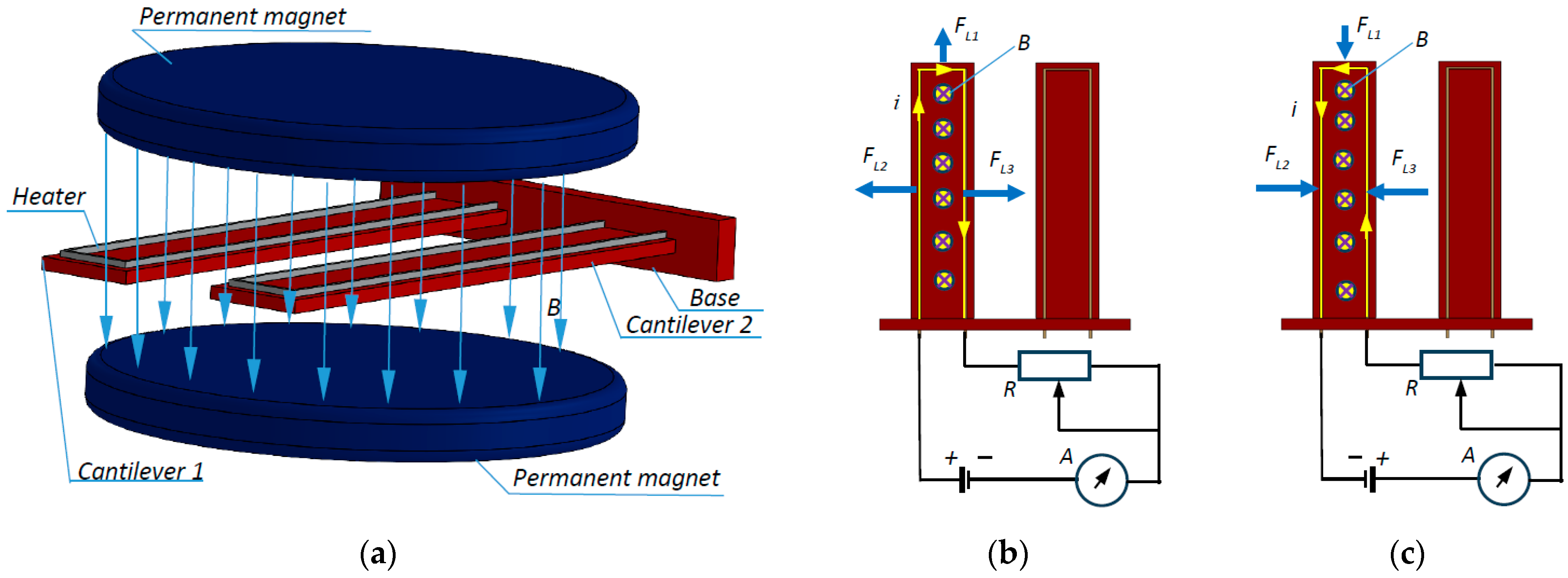
To investigate the influence of Lorentz forces on the natural frequency of a microcantilever with anisotropic properties, an experimental setup was designed, which is schematically shown in Figure 3a. Two stacks of neodymium permanent magnets created a magnetic field, the magnetic lines of which were oriented perpendicularly to the planes of the microcantilevers. As shown in Figure 3b, the heater of microcantilever 1 was plugged into an electrical circuit composed of a battery, an ammeter, and a variable resistor to regulate the current; the microcantilever was loaded in planar bidirectional tension longitudinally and transversely. To investigate the influence of the reverse directions of the Lorentz forces with compression action, the polarity of the battery was inverted (Figure 3c).
According to Lorentz’s law, a force F L occurs in the heater wire. This force is calculated by the formula
F L = i l × B ,
where i is the current, l is the length of the wire, and B is the magnetic field induction. As shown in Figure 3b,c, there were three sections in the U-shaped heater, two with lengths l h 1 and one with length l h 2 , and a Lorentz force occurred in each of these sections.
Since the heater frames moved parallelly to magnetic field lines when they vibrated, no Faraday effect voltages were induced in them.
If the orientation and direction of the magnetic induction and the direction of the current are as shown in Figure 2b, three forces occur, which can be represented by the following scalar expressions:
F L 1 = i l h 2 B F L 2 = i l h 1 B F L 3 = F L 2
The force F L 1 loads the cantilever in tension longitudinally, and the forces F L 2 and F L 3 load it in tension transversely. If only the direction of the current or only the direction of the magnetic induction is reversed, analogous forces occur, but with opposite directions, and the microcantilever is loaded entirely in compression. In either case, the microcantilever changes its natural frequency because of the increase or decrease in size and the change in Young’s modulus.
For the following calculations, it is assumed that the microcantilevers are homogeneous, of constant thickness, and made of silicon, and the influence of the thin layers of aluminum and gold is neglected. The influence of the leads and doped areas of the piezoresistors is also neglected.
Silicon is an anisotropic material for which, for type n and microcantilever location in the plane (100) and direction [ 1 1 ¯ 0 ] , the mechanical stresses are computed by Hook’s law [4,28] by multiplying the matrices
σ 1 σ 2 0 0 0 0 = C 11 C 12 C 12 0 0 0 C 12 C 11 C 12 0 0 0 C 12 C 12 C 11 0 0 0 0 0 0 C 44 0 0 0 0 0 0 C 44 0 0 0 0 0 0 C 44 ε 1 ε 2 ε 3 ε 4 ε 5 ε 6 ,
which leads to the linear system of equations
σ 1 = C 11 ε 1 + C 12 ε 2 + C 12 ε 3 σ 2 = C 11 ε 2 + C 12 ε 1 + C 12 ε 3 0 = C 11 ε 3 + C 12 ε 1 + C 12 ε 2 ,
whence the strains are found
ε 1 = C 11 σ 1 + C 12 σ 1 C 12 σ 2 C 11 C 12 C 11 + 2 C 12 ε 2 = C 11 σ 2 C 12 σ 1 + C 12 σ 2 C 11 C 12 C 11 + 2 C 12 ε 3 = C 12 σ 1 + σ 2 2 C 12 2 C 11 C 12 C 11 2 .
Here, C = C i j is the elasticity matrix, σ = σ i is the mechanical stress matrix, and ε = ε i is the strain matrix [29].
Having assumed l h 2 = l 2 and l h 1 = l 1 , the mechanical stresses are calculated using the formulae
σ 1 = ± F L 1 l 2 l 3 = ± i B l 3 σ 2 = ± F L 2 l 1 l 3 = ± i B l 3 ,
where the “+” sign is for tension (Figure 3b) and the “−” sign is compression (Figure 3c).
From (7), it is evident that for the Lorentzian loading thus specified, the mechanical stresses in both directions of the microcantilever are equal regardless of the ratio of the length to the width of the microcantilever.
If the original length, width, and thickness of the microcantilever are denoted by l 10 , l 20 , and l 30 , respectively, and the resulting deformed dimensions due to loading are denoted by l 1 , l 2 , and l 3 , respectively, the relationships can be written
l 1 = l 10 1 + ε 1 , l 2 = l 20 1 + ε 2 , l 3 = l 30 1 + ε 3 .
In this case, the newly obtained volume of the microcantilever due to the change in its dimensions is
V 1 = l 1 l 2 l 3 = V 0 ε 1 ε 2 ε 3 + ε 1 ε 2 + ε 1 ε 3 + ε 2 ε 3 + ε 1 + ε 2 + ε 3 + 1 ,
where V 0 denotes the initial undeformed volume of the microcantilever.
Since the mass does not change, the density of the deformed beam is
ρ 1 = m V 1 = m V 0 ε 1 ε 2 ε 3 + ε 1 ε 2 + ε 1 ε 3 + ε 2 ε 3 + ε 1 + ε 2 + ε 3 + 1 .
The cross-sectional area A 1 of the deformed beam is obtained as
A 1 = l 2 l 3 = A 0 ε 2 ε 3 + ε 2 + ε 3 + 1 ,
where A 0 denotes the area of the undeformed beam.
For the moment of inertia I 1 of the deformed microcantilever, it is analogously derived as
I 1 = l 2 l 3 3 12 = I 0 12 ε 2 ε 3 3 + 3 ε 2 ε 3 2 + ε 3 3 + 3 ε 2 ε 3 + 3 ε 3 2 + ε 2 + ε 3 + 1 ,
where I 0 is the moment of inertia of the undeformed microcantilever.
The changed natural angular frequency ϖ 1 of the deformed microcantilever after considering the above conclusions can be calculated [30,31] by the formula
ϖ 1 = 4.694 2 E I 1 ρ 1 A 1 l 1 4 = ω 10 1 + ε 3 2 1 + ε 2 1 + ε 1 3 ,
where ϖ 10 is the natural angular frequency of the undeformed microcantilever.
After substituting (6) into (13) and assuming the notations
σ 1 = σ 2 = σ ,
using the result in (7), after transformations for the natural angular frequency changed due to the deformations, is found
ϖ 1 = ϖ 10 C 11 2 + C 11 C 12 2 C 12 C 12 + σ 3 C 11 C 12 C 11 2 + C 12 + σ C 11 C 12 2 2 C 11 + 2 C 12 .
To match the newly assumed notations, Formula (7) can be rewritten as
σ = ± i B l 30 ,
and after substitution in (15),
ϖ 1 = ϖ 10 2 C 12 B i l 30 C 2 C 1 3 l 30 C 1 l 30 C 2 C 1 + C 11 B i 2 C 2
is obtained.
The dependence between the regular natural frequency f s 1 of the undeformed microcantilever and the resulting natural frequency f s 11 due to deformations from Lorentz forces has the form
f s 11 = f s 1 l 30 C 2 C 1 2 C 12 B i 3 l 30 C 1 l 30 C 2 C 1 + C 11 B i 2 C 2 .
In the above two formulae, substitutions are made:
C 1 = C 11 + 2 C 12 C 2 = C 11 C 12 .
Formulae (17) and (18) can be used to calculate the dependence of the natural frequency variation on the current when deforming the beam with Lorentz force at constant magnetic induction.

4. Experimental Study of the Influence of Lorentz Forces on the Amplitude–Frequency Response of a Dual-Microcantilever Sensor

To experimentally investigate the influence of Lorentz forces on the natural frequency of a dual-microcantilever sensor, a dedicated measurement system was set up (Figure 4). The general appearance of the measurement system is shown in Figure 4a. A National Instruments PXI system with 24-bit resolution and a 2 MS/s sample rate was used to record and process the voltage data from the Wheatstone bridge. To implement the above processing method, a LabVIEW 2011 program was compiled to measure high-frequency vibrations with frequencies up to 300 kHz and a minimum resolution of 0.01 Hz [5]. Additionally, two stacks of neodymium magnets were added to the system, which were designed to interact with the microcantilever heaters if current flowed on them. Lorentz forces acted in the plane of the microcantilever and caused tension or compression depending on the direction of the current in the heater. Figure 4b shows a close-up view of the integrated sensor. A piezoelectric actuator drove the base of the two microcantilevers via a Digilent controlled signal generator. Current was supplied to the heater of one of the microcantilevers via a battery through variable resistors. The value of the current was controlled by means of an ammeter.
Experiments on the effect of Lorentz forces on the natural frequency were conducted over a range from 64 kHz to 68 kHz, which included the natural frequencies of the two microcantilevers. The selected frequency range was divided into 400 steps. For each step at these frequencies, vibrations of the order of several periods were generated, and the maximum amplitude between the extreme voltages of the half-bridges involving the piezoresistors of the two microcantilevers separately and the output of the Wheatstone bridge were measured. Using LabVIEW, the results were recorded in an Excel file and then processed in Maple 16.
The heater of microcantilever 1 was initially connected electrically according to the scheme shown in Figure 3b, and then the voltage polarization was inverted (Figure 3c). A series of experiments was also conducted in the manner described above, where for each current applied to the heater, the sensor was first in a position between the two stacks of magnets and then in a position without magnetic field. The electric current in the heaters was varied from −750 to 750 µA through a current step of 25 µA. As a result, 60 files were obtained with the recorded voltage differences of the amplitude–frequency characteristics of the two half-bridges and the currents in the heaters. The sensor geometrical parameters, material data, and experimental setup are given in Table 1.
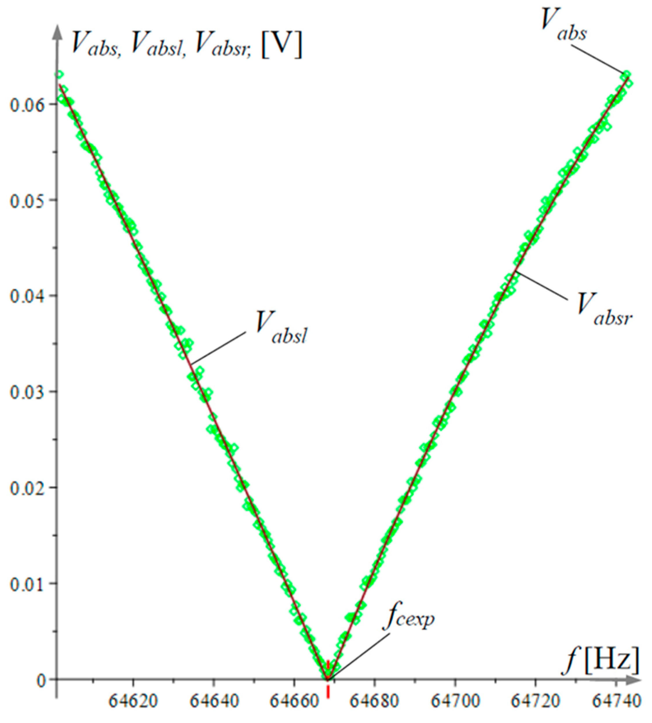
In each Excel file, the smallest value in the amplitude–frequency response array was found using Maple, and the array was divided into left decreasing and right increasing parts. The two parts of the array were approximated by parabolas, and their intersection point, called the experimental cusp point, was found from the equation
a l + b l f c exp + c l f c exp 2 = a r + b r f c exp + c r f c exp 2 ,
where a i , b i , and c i ( i = r , l ) are approximation coefficients.
Figure 5 illustrates the processing of the experimental results for a single file.
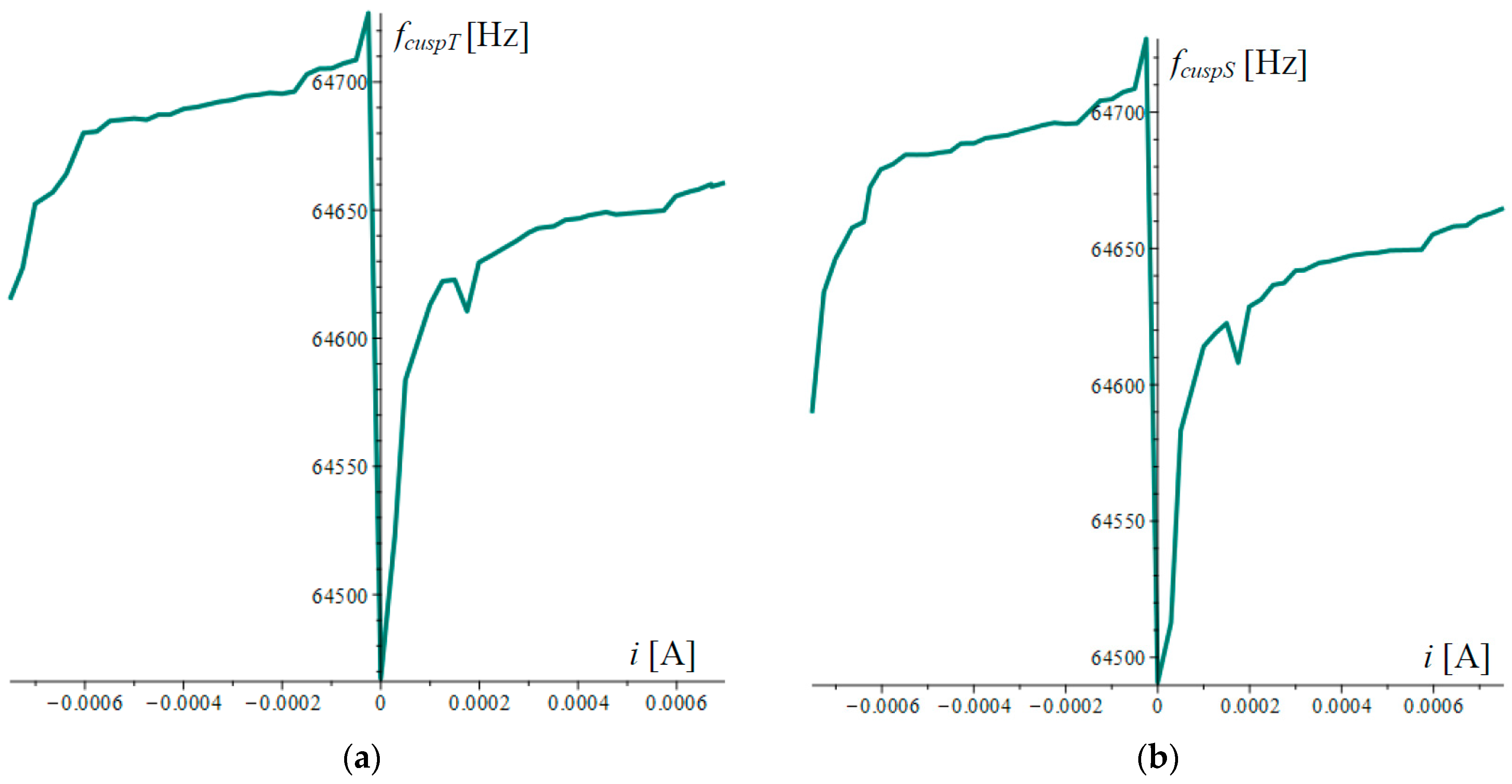
Figure 6 shows the data for experimental cusp-point frequency under thermal action only and under mixed thermal and magnetic action. The plot in Figure 6a shows the experimental frequency f c u s p T of the cusp points under pure heating, with no Lorentz forces acting. This graph shows only the thermal variation in the frequency. Figure 6b shows the graph of the frequency f c u s p S of the cusp points under the combined action of heat and Lorentz force. As can be seen from the two graphs, the differences were negligible, and thermal action played a dominant role even at small currents on the order of 25 µA.
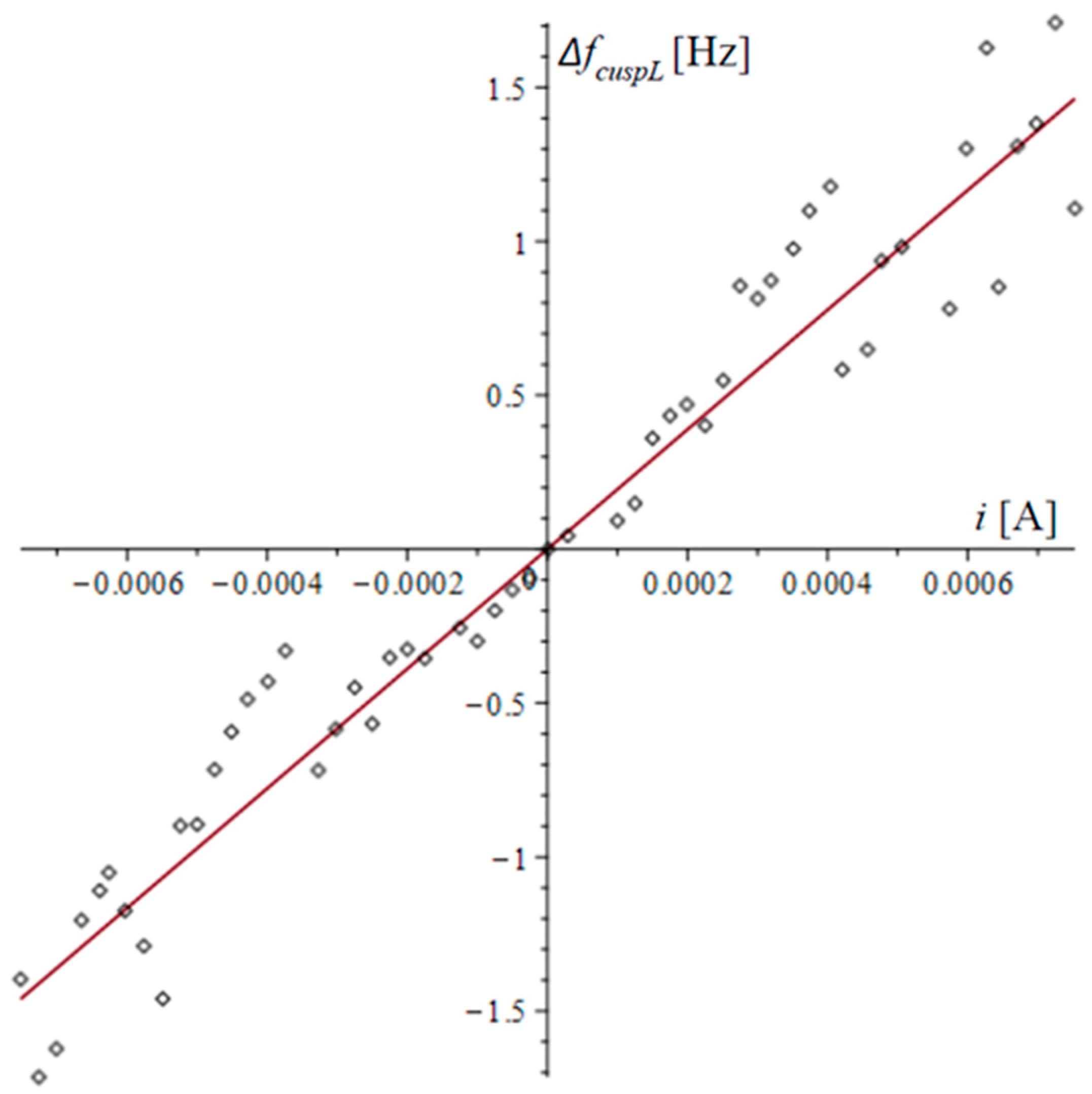
From the combined magnetic and thermal action data (Figure 6b), the thermal action data (Figure 6a) were extracted; these data are shown in Figure 7. The linear approximation of the same data is shown in the same figure.
The conclusion of the dominant frequency-dependent thermal offset action is confirmed in Figure 7, where it is evident that the thermal action changed the frequency by a factor of 80 relative to the Lorentz forces.
The large scatter in the data in Figure 7 is due to the small differences in the temperature and mixed data, which resulted in Lorentz frequencies with errors close to the accuracy of the measurement method.
The equation of the approximating line in Figure 7 is
Δ f c u s p L = 1943.73392 i .
From Formula (18), the natural frequency offset Δ f s 1 due to Lorentz forces was derived as
Δ f s 1 = f s 11 f s 1 = f s 1 l 30 C 2 C 1 2 C 12 B i 3 l 30 C 1 l 30 C 2 C 1 + C 11 B i 2 C 2 1 ,
where f s 11 is the changed value of the natural frequency of microcantilever 1. Taking into account the small values of the current i , from (22), Δ f s 1 was expanded in a Maclaurin series of the second order, obtaining
Δ f s 1 f s 1 B C 11 + 3 C 12 l 30 C 1 C 2 i + O i 2 .
After the substitution
f s 11 = f s 1 + Δ f s 1
in Formula (1), the offset frequency f c u s p 1 was represented in the form
f c u s p 1 = 2 2 f s 1 + Δ f s 1 4 f s 2 4 f s 1 + Δ f s 1 2 f s 2 2 2 η 1 2 η 2 2 ,
which was expanded in the Maclaurin series versus the small difference Δ f s 1 , obtaining
f c u s p 1 f c u s p 1 + 4 η 1 2 f s 1 2 η 2 2 f s 2 2 f s 1 2 f s 2 2 2 2 η 1 2 f s 1 2 2 η 2 2 + f s 2 2 f s 1 4 f s 2 4 f s 1 Δ f s 1 + O Δ f s 1 2 .
For the offset of the cusp point Δ f c u s p in this case followed the relation
Δ f c u s p = f c u s p 1 f c u s p f c u s p 4 η 1 2 f s 1 2 η 2 2 f s 2 2 f s 10 2 f s 2 2 2 2 η 1 2 f s 1 2 2 η 2 2 + f s 2 2 f s 1 4 f s 2 4 f s 1 Δ f s 1 .
The natural frequency increment Δ f s 1 was substituted by (23), and the linear function
Δ f c u s p = f c u s p f s 1 2 B 4 f s 1 2 η 1 2 η 2 2 f s 1 2 f s 2 2 2 C 11 + 3 C 12 l 30 C 1 C 2 2 η 1 2 f s 1 2 2 η 2 2 + f s 2 2 f s 2 4 f s 1 4 i
was obtained. The coefficient prior in (28), compared with that in (21), was used to evaluate the accuracy of the experiment.

5. Conclusions

Using a specialized experimental setup, investigations into the cusp-point frequency offset in the amplitude–frequency response of a dual-microcantilever piezoresistive sensor were conducted. The two microcantilevers of the sensor had heaters made of thin aluminum film, which heated the microcantilevers, and Lorentz forces occurred when a magnetic field was applied along with the heating. With the same current in the heater of one of the microcantilevers, first, the frequency offset under the combined influence of Lorentz forces and heating was measured, and then the frequency offset in the absence of Lorentz forces was determined. After eliminating the thermal influence, results were obtained for the influence of only Lorentz forces on the cusp point of the amplitude–frequency response, and then for the natural frequency variation of the microcantilever.
The theoretical relationships for the anisotropic deformation of silicon microcantilevers due to Lorentz forces have been derived, and the theoretical relationship between the variation in the natural frequency and the current in the heater has been determined.
It was found that for a microcantilever sensor with a beam mass of the order of a few ng, at a minimum heater current of 25 µA, the variations in the natural frequency due to temperature were dominant and an order of magnitude higher than those due to Lorentz forces. These conclusions were made by measuring with steady-state temperatures. Most micromechanical devices work in resonance, allowing a very short pulse of the driving stimulus to be applied. Under such conditions, one can rely on Lorentz forces, which, when acting under steady-state temperatures, can be dominant over thermal influence.
Through experiments and some theoretical deductions, it was found that regardless of the direction of the current, thermal action resulted only in a reduction in the natural frequency. The Lorentz force can increase or decrease the natural frequency of the microcantilever depending on the direction of the current or the direction of the magnetic field polarization. To change the frequency of a microcantilever with the Lorentz force, it is possible to use an electromagnet, which brings more tuning possibilities.
Changes in frequency, whether by temperature or Lorentz forces, can be used to test the suitability of sensors to detect small masses that will cause the same frequency changes.
The conclusions obtained here may be useful in the design of other types of vibration sensors or actuators in which the natural frequency needs to be tuned or controlled.

Author Contributions

Conceptualization, L.B., B.G., G.T. and T.T.; methodology, B.G. and T.T.; software, B.G.; validation, V.S., B.G. and T.T.; formal analysis, G.T.; investigation, B.G. and L.B.; resources, V.S.; data curation, V.S.; writing—original draft preparation, T.T. and L.B.; writing—review and editing, V.S.; visualization, B.G.; supervision, G.T.; project administration, G.T.; funding acquisition, G.T. All authors have read and agreed to the published version of the manuscript.

Funding

This research was funded by the European Union’s NextGenerationEU through the National Recovery and Resilience Plan of the Republic of Bulgaria, project № BG-RRP-2.004-0005.

Institutional Review Board Statement

Not applicable.

Informed Consent Statement

Not applicable.

Data Availability Statement

Data are contained within the article.

Conflicts of Interest

The authors Vladimir Stavrov was employed by the company AMG Technology Ltd. The authors declare that the research was conducted in the absence of any commercial or financial relationships that could be construed as potential conflicts of interest.

References

  1. Breuer, K.S.; Park, J.; Henoch, C. Actuation and Control of a Turbulent Channel Flow Using Lorentz Forces. Phys. Fluids 2004, 16, 897–907. [Google Scholar] [CrossRef]
  2. Herrera-May, A.; Soler-Balcazar, J.; Vázquez-Leal, H.; Martínez-Castillo, J.; Vigueras-Zuñiga, M.; Aguilera-Cortés, L. Recent Advances of MEMS Resonators for Lorentz Force Based Magnetic Field Sensors: Design, Applications and Challenges. Sensors 2016, 16, 1359. [Google Scholar] [CrossRef] [PubMed]
  3. Kwang, W.O.; Chong, H. Ahn Magnetic Actuation. In Comprehensive Microsystems; Gianchandani, Y.B., Tabata, O., Zappe, H., Eds.; Elsevier Ltd.: Amsterdam, The Netherlands, 2008; Volume 2, pp. 42–43. [Google Scholar]
  4. Allen, J.J. Micro Electro Mechanical System Design, 1st ed.; Taylor & Francis Group, LLC.: New York, NY, USA, 2005; Volume 1. [Google Scholar]
  5. Basha, H.; Nandeppanavar, M.M.; Reddy, G.J. Dissipative Lorentz Force Influence on Mass Flow over a Micro-cantilever Sensor Sheet under Magnetic Ohmic Heating. ZAMM J. Appl. Math. Mech. Z. Angew. Math. Mech. 2024, 104, 55. [Google Scholar] [CrossRef]
  6. Lv, X.; Wei, W.; Mao, X.; Yang, J.; Yang, F. A Novel MEMS Actuator with Large Lateral Stroke Driven by Lorentz Force. J. Micromech. Microeng. 2015, 25, 025009. [Google Scholar] [CrossRef]
  7. Keplinger, F.; Kvasnica, S.; Jachimowicz, A.; Kohl, F.; Steurer, J.; Hauser, H. Lorentz Force Based Magnetic Field Sensor with Optical Readout. Sens. Actuators A Phys. 2004, 110, 112–118. [Google Scholar] [CrossRef]
  8. Gkotsis, P.; Lara-Castro, M.; López-Huerta, F.; Herrera-May, A.L.; Raskin, J.-P. Mechanical Characterization and Modelling of Lorentz Force Based MEMS Magnetic Field Sensors. Solid State Electron. 2015, 112, 68–77. [Google Scholar] [CrossRef]
  9. Treutler, C.P.O. Magnetic Sensors for Automotive Applications. Sens. Actuators A Phys. 2001, 91, 2–6. [Google Scholar] [CrossRef]
  10. Li, M.; Nitzan, S.; Horsley, D.A. Frequency-Modulated Lorentz Force Magnetometer with Enhanced Sensitivity via Mechanical Amplification. IEEE Electron. Device Lett. 2015, 36, 62–64. [Google Scholar] [CrossRef]
  11. Mbarek, S.B.; Alcheikh, N.; Ouakad, H.M.; Younis, M.I. Highly Sensitive Low Field Lorentz-Force MEMS Magnetometer. Sci. Rep. 2021, 11, 21634. [Google Scholar] [CrossRef]
  12. Tu, C.; Ou-Yang, X.; Wu, Y.; Zhang, X. Single-Structure 3-Axis Lorentz Force Magnetometer Based on an AlN-on-Si MEMS Resonator. Microsyst. Nanoeng. 2024, 10, 58. [Google Scholar] [CrossRef]
  13. Lee, B.; Prater, C.B.; King, W.P. Lorentz Force Actuation of a Heated Atomic Force Microscope Cantilever. Nanotechnology 2012, 23, 055709. [Google Scholar] [CrossRef] [PubMed]
  14. Alunda, B.O.; Lee, Y.J. Review: Cantilever-Based Sensors for High Speed Atomic Force Microscopy. Sensors 2020, 20, 4784. [Google Scholar] [CrossRef]
  15. Somnath, S.; Liu, J.O.; Bakir, M.; Prater, C.B.; King, W.P. Multifunctional Atomic Force Microscope Cantilevers with Lorentz Force Actuation and Self-Heating Capability. Nanotechnology 2014, 25, 395501. [Google Scholar] [CrossRef]
  16. Zhang, W.; Lee, J.E.-Y. Frequency-Based Magnetic Field Sensing Using Lorentz Force Axial Strain Modulation in a Double-Ended Tuning Fork. Sens. Actuators A Phys. 2014, 211, 145–152. [Google Scholar] [CrossRef]
  17. Liepe, M.; Moeller, W.D.; Simrock, S.N. Dynamic Lorentz Force Compensation with a Fast Piezoelectric Tuner. In Proceedings of the 2001 Particle Accelerator Conference (Cat. No.01CH37268), Chicago, IL, USA, 18–22 June 2001; IEEE: New York, NY, USA, 2001; pp. 1074–1076. [Google Scholar]
  18. Mehdizadeh, E.; Kumar, V.; Pourkamali, S. Sensitivity Enhancement of Lorentz Force MEMS Resonant Magnetometers via Internal Thermal-Piezoresistive Amplification. IEEE Electron. Device Lett. 2014, 35, 268–270. [Google Scholar] [CrossRef]
  19. Shiraishi, N.; Kimura, M.; Ando, Y. Basic Characteristics of Polycarbonate-Based Dual Cantilever Sensors for Detecting VOC. Mech. Eng. J. 2014, 1, MN0055. [Google Scholar] [CrossRef]
  20. Gurjar, M.; Jalili, N. Toward Ultrasmall Mass Detection Using Adaptive Self-Sensing Piezoelectrically Driven Microcantilevers. IEEE/ASME Trans. Mechatron. 2007, 12, 680–688. [Google Scholar] [CrossRef]
  21. Toda, M.; Inomata, N.; Ono, T.; Voiculescu, I. Cantilever Beam Temperature Sensors for Biological Applications. IEEJ Trans. Electr. Electron. Eng. 2017, 12, 153–160. [Google Scholar] [CrossRef]
  22. Abedinov, N.; Grabiec, P.; Gotszalk, T.; Ivanov, T.; Voigt, J.; Rangelow, I.W. Micromachined Piezoresistive Cantilever Array with Integrated Resistive Microheater for Calorimetry and Mass Detection. J. Vac. Sci. Technol. A Vac. Surf. Film. 2001, 19, 2884–2888. [Google Scholar] [CrossRef]
  23. Ramos, D.; Calleja, M.; Mertens, J.; Zaballos, A.; Tamayo, J. Measurement of the Mass and Rigidity of Adsorbates on a Microcantilever Sensor. Sensors 2007, 7, 1834–1845. [Google Scholar] [CrossRef]
  24. Jin, D.; Li, X.; Liu, J.; Zuo, G.; Wang, Y.; Liu, M.; Yu, H. High-Mode Resonant Piezoresistive Cantilever Sensors for Tens-Femtogram Resoluble Mass Sensing in Air. J. Micromech. Microeng. 2006, 16, 1017–1023. [Google Scholar] [CrossRef]
  25. Banchelli, L.; Todorov, G.; Stavrov, V.; Ganev, B.; Todorov, T. Investigating a Detection Method for Viruses and Pathogens Using a Dual-Microcantilever Sensor. Micromachines 2024, 15, 1117. [Google Scholar] [CrossRef] [PubMed]
  26. Banchelli, L.F.; Ganev, B.T.; Todorov, T.S. Sustainability Validation of a LabVIEW Based System for Biomarkers Detection. In Proceedings of the 2023 XXXII International Scientific Conference Electronics (ET), Sozopol, Bulgaria, 13–15 September 2023; IEEE: New York, NY, USA, 2023; pp. 1–6. [Google Scholar]
  27. Stavrov, V.; Stavreva, G.; Tomerov, G. Tester for Detection of Infectious Agents in Fluid. Bulgarian Patent BG113123A, 16 April 2020. [Google Scholar]
  28. Liu, C. Foundations of MEMS, 2nd ed.; Prentice Hall, 2 Pearson Education, Inc.: Upper Saddle River, NY, USA, 2011. [Google Scholar]
  29. McCarter, D.R.; Paquin, R.A. Isotropic Behavior of an Anisotropic Material: Single Crystal Silicon. In Proceedings SPIE Material Technologies and Applications to Optics, Structures, Components, and Sub-Systems; Robichaud, J.L., Krödel, M., Goodman, W.A., Eds.; SPIE: Paris, France, 2013; Volume 8837, p. 883707. [Google Scholar]
  30. Volterra, E.; Zachmanoglou, E.C. Dynamics of Vibrations; C.E. Merrill Books: New York, NY, USA, 1965; Volume 1. [Google Scholar]
  31. Meirovitch, L. Elements of Vibration Analysis, 2nd ed.; McGraw-Hill: New York, NY, USA, 1986. [Google Scholar]
  32. Lindroos, V.; Tilli, M.; Lehto, A. Handbook of Silicon Based MEMS Materials and Technologies; Elsevier: Amsterdam, The Netherlands, 2010; ISBN 9780815515944. [Google Scholar]
  33. Keyes, R.W. Electronic Effects in the Elastic Properties of Semiconductors. In Solid State Physics; Seitz, F., Turnbull, D., Ehrenreich, H., Eds.; Elsevier: Amsterdam, The Netherlands, 1968; Volume 20, pp. 37–90. [Google Scholar]
Figure 1. Arrangement and elements of the piezoresistive dual-microcantilever sensor: (a) simplified 3D sketch; (b) picture of the chip topology; (c) appearance of the sensor chip.
Micro 04 00035 g001
Figure 2. Amplitude–frequency characteristics of the dual-microcantilever sensor: (a) voltage differences of the two half-bridges; (b) absolute value of the voltage difference of the two half-bridges.
Micro 04 00035 g002
Figure 3. Loading of microcantilever 1 with Lorentz forces: (a) schematic of the mutual orientation of the two microcantilevers in a homogeneous magnetic field with induction B perpendicular to the plane of the beam; (b) microcantilever heater power supply 1 with adjustable current i; (c) microcantilever 1 heater power supply with adjustable current i in the reverse direction.
Micro 04 00035 g003
Figure 4. Experimental setup for testing piezoresistive sensors with two microcantilevers: (a) general view; (b) sensor with magnet stacks. 1, sensor; 2, NI PXI system; 3, ammeter; 4, Digilent sine signal generator; 5, variable resistors for current regulation in the microcantilever heater; 6, batteries; 7, monitor; 8, microchip; 9, piezoelectric actuator; 10, sensor housing; 11, neodymium magnet stacks.
Micro 04 00035 g004
Figure 5. Experimental data processing of an Excel file obtained at current i = −750 µA. V a b s is the measured shifted voltage, V a b s l is the approximated left parabola, V a b s r is the approximated right parabola, and f c e x p is the experimentally obtained cusp point.
Micro 04 00035 g005
Figure 6. Cusp-point frequency shift under the influence of Lorentz forces and temperature–frequency coefficient: (a) thermal frequency shift only; (b) sum of thermal and Lorentz effects.
Micro 04 00035 g006
Figure 7. Frequency offset of the cusp-point amplitude–frequency response of the dual-microcantilever sensor.
Micro 04 00035 g007
Table 1. Data for dual-microcantilever sensor and experimental setup.
ParameterSymbolUnitValue
Magnetic flux density of the magnet stackBT0.0022
Length 1 of the microcantilever 1 heater l h 1 M292 × 10−6
Length 2 of the microcantilever 1 heater l h 2 M148 × 10−6
Length of microcantilever 1 l 11 M294 × 10−6
Length of microcantilever 2 l 12 M292 × 10−6
Width of microcantilever 1 l 21 M150 × 10−6
Width of microcantilever 2 l 22 M172 × 10−6
Height of microcantilever 1 l 31 m4 × 10−6
Height of microcantilever 2 l 32 m4 × 10−6
Density of silicon ρ kg/m32329 *
Mass of the silicon in cantilever 1 m 1 kg4.11 × 10−10
Mass of the silicon in cantilever 2 m 2 kg4.62 × 10−10
Young’s modulus of the n silicon in [110] direction E 110 GPa170 **
Stiffness for n type silicon plane 100 in axis [010] C 12 Pa63.94 × 109 **
Stiffness for n type silicon plane 100 in axis [001] C 44 Pa79.51 × 109 **
Stiffness for n type silicon plane 100 in axis [110] C 11 Pa165.65 × 109 **
Natural angular frequency of microcantilever 1 ϖ 1 s−110,402.535
Natural angular frequency of microcantilever 2 ϖ 2 s−110,568.028
Natural frequency of microcantilever 1 f s 1 Hz65,361.057
Natural frequency of microcantilever 2 f s 2 Hz66,400.888
Frequency of the cusp point f c u s p Hz65,889.063
Damping factor of microcantilever 1 β 1 s−11554.755
Damping factor of microcantilever 2 β 2 s−11675.886
* According to data from [32]. ** According to data from [33].
Disclaimer/Publisher’s Note: The statements, opinions and data contained in all publications are solely those of the individual author(s) and contributor(s) and not of MDPI and/or the editor(s). MDPI and/or the editor(s) disclaim responsibility for any injury to people or property resulting from any ideas, methods, instructions or products referred to in the content.