Article

Strain Gradient Theory Based Dynamic Mindlin-Reissner and Kirchhoff Micro-Plates with Microstructural and Micro-Inertial Effects

by
Stylianos Markolefas
1,† and
Dimitrios Fafalis
2,*,†
1
Core Department, National and Kapodistrian University of Athens, 344 00 Psachna Euboea, Greece
2
Department of Mechanical Engineering and Mechanics, Drexel University, Philadelphia, PA 19123, USA
*
Author to whom correspondence should be addressed.
These authors contributed equally to this work.
Dynamics 2021, 1(1), 49-94; https://doi.org/10.3390/dynamics1010005
Submission received: 11 June 2021 / Revised: 23 July 2021 / Accepted: 26 July 2021 / Published: 31 July 2021

Abstract

:
In this study, a dynamic Mindlin–Reissner-type plate is developed based on a simplified version of Mindlin’s form-II first-strain gradient elasticity theory. The governing equations of motion and the corresponding boundary conditions are derived using the general virtual work variational principle. The presented model contains, apart from the two classical Lame constants, one additional microstructure material parameter g for the static case and one micro-inertia parameter h for the dynamic case. The formal reduction of this model to a Kirchhoff-type plate model is also presented. Upon diminishing the microstructure parameters g and h, the classical Mindlin–Reissner and Kirchhoff plate theories are derived. Three points distinguish the present work from other similar published in the literature. First, the plane stress assumption, fundamental for the development of plate theories, is expressed by the vanishing of the z-component of the generalized true traction vector and not merely by the zz-component of the Cauchy stress tensor. Second, micro-inertia terms are included in the expression of the kinetic energy of the model. Finally, the detailed structure of classical and non-classical boundary conditions is presented for both Mindlin–Reissner and Kirchhoff micro-plates. An example of a simply supported rectangular plate is used to illustrate the proposed model and to compare it with results from the literature. The numerical results reveal the significance of the strain gradient effect on the bending and free vibration response of the micro-plate, when the plate thickness is at the micron-scale; in comparison to the classical theories for Mindlin–Reissner and Kirchhoff plates, the deflections, the rotations, and the shear-thickness frequencies are smaller, while the fundamental flexural frequency is higher. It is also observed that the micro-inertia effect should not be ignored in estimating the fundamental frequencies of micro-plates, primarily for thick plates, when plate thickness is at the micron scale (strain gradient effect).

1. Introduction

In recent years, an increasing attention on size-dependent theories of continuum mechanics is observed, as a result of the need to develop and investigate the behavior of structural elements, like micro-bars, micro-beams, and micro-plates, used in applications of the blooming technologies of micro- and nano-electromecanical systems (MEMS; NEMS) [1,2,3,4,5,6].
The mechanical behavior of these micro- or nano-structures is strongly affected by the material microstructure, in cases when their dimensions are comparable to the material internal length scale. The importance of microstructure length scales is well demonstrated by experiments on particular geometries of the micro- and nano-scale. The existence of material microstructure is responsible for various scale effects, such as the changes in wave propagation dispersion curves, the increased bending stiffness of ultra-thin beams, the finite-valued stress fields on the crack tips, etc. [7,8,9,10,11]. These scale effects cannot be predicted/captured by the classical theory of continuum mechanics, as no intrinsic length scales are included in the constitutive theory. For this reason, various generalized continuum mechanics theories have been developed that take into account material length scale parameters.
The most well-known and widely used theories are the nonlocal theory of elasticity [12,13,14], the couple-stress theory of elasticity [15], the micropolar theory of elasticity [16,17], and Mindlin’s strain gradient elasticity [18,19,20]. In this paper a simplified version of Mindlin’s first-strain gradient elasticity is adopted to model shear-deformable plates, (see also in [4,21,22,23,24,25,26,27,28,29,30,31,32,33,34]). All above theories include scale effects rendering them appropriate for modeling micro- and nanostructures, like MEMS and NEMS.
For completeness purposes, we mention in the sequence some noteworthy works the results of which will be used to compare with those produced by the present work.
Considering at first the nonlocal elasticity theory, we mention the works of Lu et al. [35] and Reddy [2]. Both works are based on the differential form of nonlocal elasticity [14,36]. In the first one, the authors developed nonlocal plate models for Kirchhoff-type and Mindlin-type plate theories, and illustrated their use in solving the problems of deflection and free vibration of a simply supported rectangular plate. In the second one, Reddy implemented the principle of virtual work to derive the static equations of equilibrium for nonlocal classical and shear-deformable beams and plates. The constitutive equations proposed were based on Von Karman’s nonlinearity of strains. The nonlocal models developed in both works maintain the same order for the governing equations, as in the classical cases.
Next, with reference to couple-stress theory, we focus on the works of Ma et al. [37] and Tsiatas [38]. In both these works, the modified couple-stress theory with one material length scale parameter [39] is employed to develop a Mindlin-type plate theory in the former work and a Kirchhoff-type plate theory in the last one.
Ma et al. [37], through the variational formulation of Hamilton’s principle, developed a Mindlin-type (shear-deformable) plate and illustrated their model in static bending and free vibration problems. On the other hand, Tsiatas applied the principle of minimum potential energy to derive a static model, which was implemented in the bending of arbitrary-shaped plates. Note that the governing equation of this model is of the fourth order, contrary to the sixth-order gradient elasticity plate models.
Finally, concerning the theory of first-strain gradient elasticity, there are three works to discuss. Lazopoulos [40] using the principle of virtual work and based on a simplified version of Mindlin’s form-II first-strain gradient elasticity developed a Kirchhoff-type plate model for the static case. In this model, apart from the classical Lame constants, two additional constitutive coefficients were introduced; the intrinsic bulk length g, associated with the microstructure, and the directional surface energy length l k , accounting for surface effects, like surface tension [19]. However, as an example, the analytical bending solution for the simply supported rectangular plate was presented, using only the intrinsic parameter g.
Parargyri-Beskou et al. [41,42] developed a Kirchhoff-type gradient plate, based on a strain-gradient theory, in which only the intrinsic parameter g is employed. The resulting governing equations of sixth-order is similar to that derived by Lazopoulos [40], except from the coefficient of the fourth-order term. This difference arouses from the fact that Lazopoulos used in his variational formulation some extra out-of-plane higher-order (double) stress components. The difference becomes more apparent when examining the deflection behavior of the plate: Lazopoulos’s model is much stiffer than the model of Papargyri-Beskou et al. [41].
A third model to consider in our discussion on strain-gradient elastic plates comes from the work of Ramezani [43]. In this work, Ramezani developed, using Hamilton’s principle, a Mindlin-type (shear-deformable) micro-plate model based on the most general form of Mindlin’s form-II first-strain gradient elasticity theory, in which five intrinsic material parameters are employed. By assigning specific values to these five parameters, this general model reduces to a Mindlin-type plate with only one intrinsic parameter, the g mentioned before. Concerning the dynamic part of the governing equations, Ramezani used the classical inertia terms, omitting the micro-inertia effects of the microstructure. Moreover, in developing the constitutive relations Ramezani used the plane stress assumption expressed by the condition that the zz-component (vertical to the plate’s mid-plane) of the Cauchy stress should vanish, i.e., τ 33 = 0 .
In this work, we develop, using the general virtual work principle, a dynamic Mindlin–Reissner-type plate based on a simplified version of Mindlin’s form-II first-strain gradient elasticity, with one intrinsic parameters, the intrinsic bulk length g. The plane stress assumption adopted herein is expressed by the vanishing of the z-axis component of the generalized traction vector, i.e., t 3 = 0 . This leads in a very natural way to identifying the detailed conditions satisfied by the respective Cauchy and double stress components, withing the current framework. In addition, micro-inertia effects are also considered in the kinetic energy of the plate, introducing the micro-inertia material parameter h. A thorough study of the micro-inertial effects in the dynamic behavior and wave dispersion of elastic micro-bars can be found in [44,45]. Note that rendering the microscopic parameters g and h equal to zero, the classical plate models are deduced.
The paper is outlined as follows: In Section 2, the basic assumptions for the plane stress condition of a Mindlin–Reissner-type plate, along with the governing constitutive equations are presented. In Section 3, the displacement behavior and the resultant forces and moments are employed, which are inserted into the general virtual work principle, in Section 4, in order to derive the governing differential equations and appropriate boundary conditions. In Section 5, a dynamic gradient Kirchhoff-type plate model is developed, which for the static case is reduced to that developed in [40]. In Section 6, we review some micro-plate models published in the literature, which are compared in Section 8 with those developed herein. In Section 7, an example of a simply supported rectangular plate is illustrated using the Navier solutions for the static bending and free vibration problems. The numerical results and a comparative discussion on them is employed in Section 8. Finally, some conclusions are envisioned in Section 9.

2. Basic Assumptions and Constitutive Relations for Grade-2 Mindlin–Reissner-Type Elastic Plates

The general 3D constitutive equations for the strain gradient elasticity model considered herein are stated as follows (using tensorial notation, see in [18,20]),
τ i j = λ ε k k δ i j + 2 G ε i j
μ i j k = g 2 λ κ i n n δ j k + 2 G κ i j k
where τ i j and μ i j k are the components of the Cauchy stress and double (or dipolar) stress tensors, respectively; κ i j k = ε j k , i are the components of the strain gradient tensor; ε i j are the components of the small strain tensor; λ , G are the well-known Lame constants; and g is a constant related to the material microstructure, see [18]. The unit of constant g is [Length]. Furthermore, Latin indices i , j , k , n take the values 1,2,3.
Recall that λ : = E ν ( 1 + ν ) ( 1 2 ν ) and G : = E 2 ( 1 + ν ) (where E is the Young’s modulus and ν is the Poisson’s ratio). The partial derivative of the variable y ( x i ) with respect to x i is represented by y , i .
Note that Equation (1) is the standard elasticity stress–strain relation for isotropic materials, and is related to (2) by μ i j k = g 2 τ j k , i .
We consider a flat plate, lying on plane x y (axis 1,2). As the plate is relatively thin and the upper and lower surfaces are stress free, it is reasonable to assume that the vertical component of the true traction vanishes identically (see, for example, Figure A1 in Appendix A),
t 3 = 0
where t 3 is the (out-of-plane) true traction, normal to the plate surface.
The general definition of the true traction in the strain gradient elasticity theory is given by the relation [18]
t k = n j τ j k μ i j k , i D j n i μ i j k + D l n l n j n i μ i j k
where D j ( ) : = δ j l n j n l ( ) , l is the surface gradient operator and n i are the components of the normal unit vector on the surface. For the current case D l n l = 0 . That is, the normal unit vector does not change along the plane. From Equation (4) it follows that
t k = n j τ j k μ i j k , i n i μ i j k , j + n j n l n i μ i j k , l
For the upper/lower surface of the plate (along the z axis), we have n 1 = n 2 = 0 and n 3 = ± 1 . Therefore, from Equation (5) we get
t 3 = τ 33 μ i 33 , i μ 3 j 3 , j + μ 333 , 3 = 0
The moment (or double traction) condition on the free surfaces [18,46] gives
n i n j μ i j k = 0 μ 33 k = μ 3 k 3 = 0
Equations (6) and (7) suggest the following relations for the plane stress conditions in the plane x y , within the framework of the strain gradient elasticity theory:
τ 33 = 0 ; μ 333 = 0 ; μ α 33 = 0 ; μ 3 α 3 = 0
for α = 1 , 2 , where the Greek indices correspond to the in-plane axes ( x , y ) and take the values 1 and 2.
Equation (8) will be used in order to develop in-plane and out-of-plane constitutive relations for the current model, describing the in-plane stress state in the plane x y . To this end, it is necessary to write Equations (1) and (2) as follows,
τ α β = λ ε k k δ α β + 2 G ε α β τ α 3 = 2 G ε α 3 τ 33 = λ ε k k + 2 G ε 33 = 0 μ α β γ = g 2 λ κ α n n δ β γ + 2 G κ α β γ μ α β 3 = g 2 2 G κ α β 3 μ 3 α β = g 2 λ κ 3 n n δ α β + 2 G κ 3 α β μ α 33 = g 2 λ κ α n n + 2 G κ α 33 = 0 μ 3 α 3 = g 2 2 G κ 3 α 3 = 0 μ 333 = g 2 λ κ 3 n n + 2 G κ 333 = 0
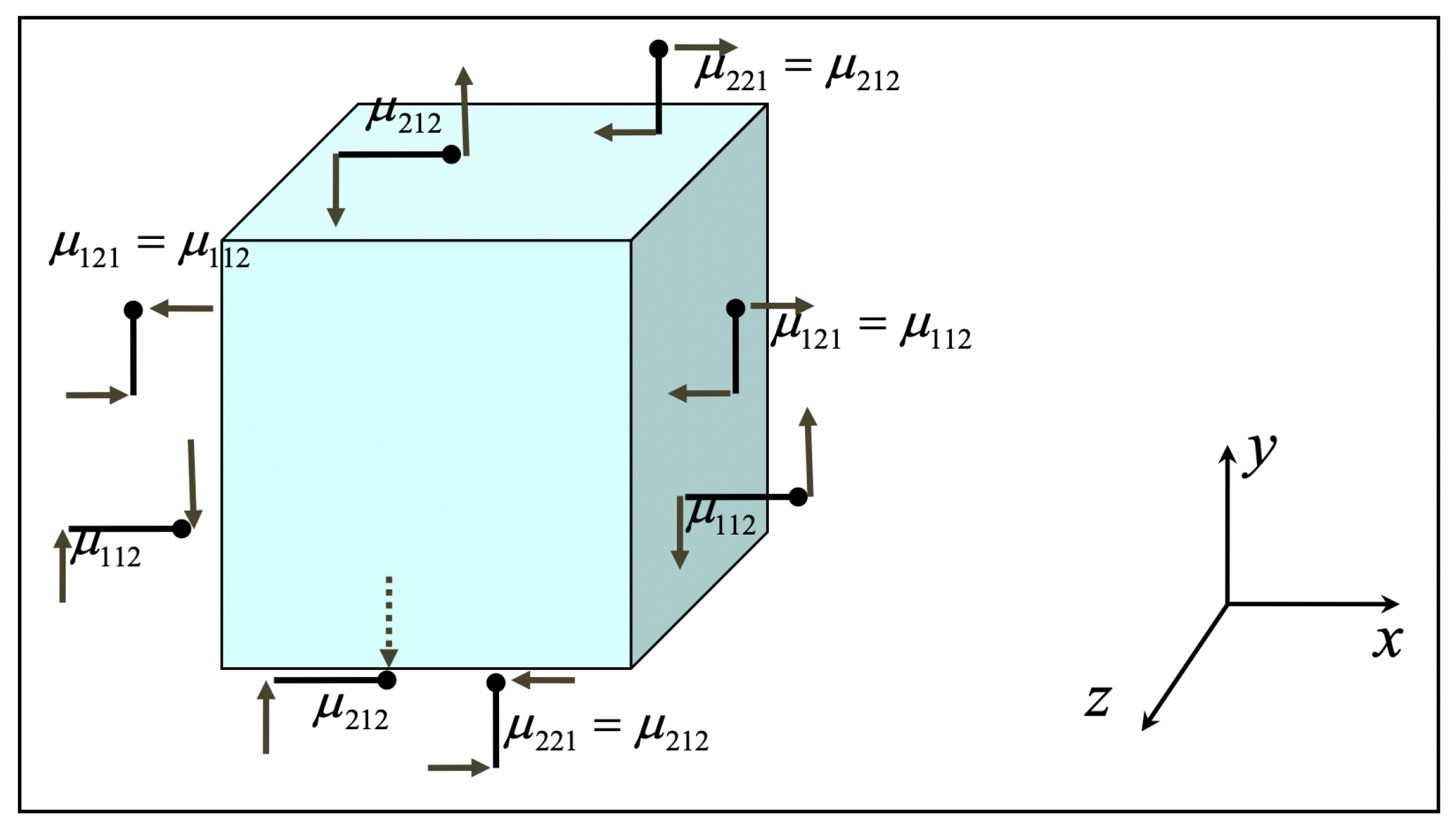
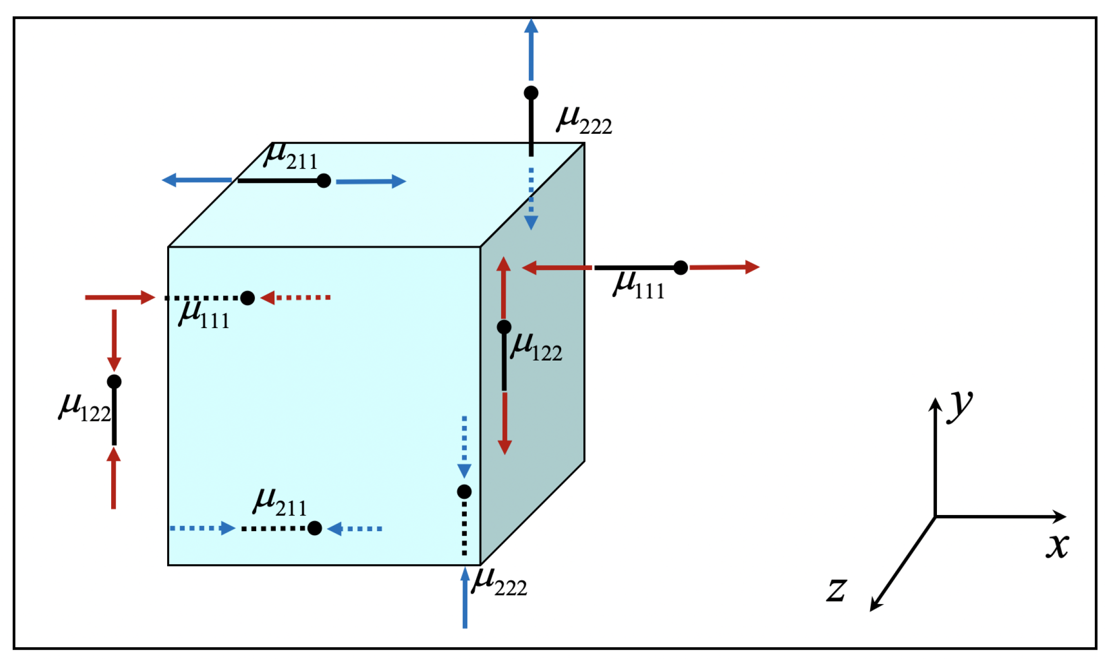
For a graphical depiction and physical demonstration of the zero and non-zero double stresses μ i j k , please refer to Appendix A.
From term τ 33 in Equation (9) it follows that
λ ε 33 + 2 G ε 33 = λ ε α α
while, from term μ α 33 in Equation (9),
g 2 2 G κ α 33 + g 2 λ κ α 33 = g 2 λ κ α β β
From Equations (10) and (11) the components ε 33 and κ α 33 in terms of the in-plane strains and strain-gradients can be solved,
ε 33 = λ λ + 2 G ε α α κ α 33 = λ λ + 2 G κ α β β
Substituting Equations (12) into terms τ α β and μ α β γ of Equation (9) we get the constitutive equations for the in-plane stresses,
τ α β = E ν 1 ν 2 ε γ γ δ α β + 2 G ε α β μ α β γ = g 2 E v 1 ν 2 κ α δ δ δ β γ + 2 G κ α β γ
where α , β , γ = 1 , 2 .
The remaining non-zero out-of-plane stress components are summarized as follows,
τ α 3 = 2 G ε α 3 μ α β 3 = g 2 2 G κ α β 3 μ 3 α β = g 2 λ κ 3 n n δ α β + 2 G κ 3 α β
It is noteworthy that the Kirchhoff-type model for gradient elastic plates developed in [41,42] employs only the in-plane relations (13), while the respective Kirchhoff-type model of [40] incorporates the contribution of the terms μ 3 α β . The current theory, which is based on a Mindlin–Reissner type approach, implies non-zero components μ 3 α β and μ α β 3 .
It is necessary to emphasize that in order to develop (13) the assumptions, τ 33 = 0 and μ α 33 = 0 have been employed, see terms τ 33 and μ α 33 in Equation (9). Obviously, μ 333 = 0 is implied by τ 33 = 0 , as μ i j k = g 2 τ j k , i . Moreover, the current theory satisfies a priori the relation, μ 3 α 3 = g 2 2 G κ 3 α 3 = 0 , as the out-of-plane shear strain γ α 3 is constant through the thickness. In higher-order shear deformation theories however, such as in Reddy or Levinson plate theories, the condition μ 3 α 3 = 0 should be satisfied only at the upper and lower free surfaces of the plate.

3. Theoretical Basis for Mindlin–Reissner-Type Elastic Plates

With reference to Figure 1, the fundamental displacement or kinematical assumptions read as follows,
u 1 = z θ 1 ( x , y ) u 2 = z θ 2 ( x , y ) u 3 = w ( x , y )
where u 1 , u 2 , and u 3 are the components of the displacement vector u along the reference axes x , y , and z respectively; ( x , y ) are the coordinates of any point on the plate’s mid-plane, z is the vertical distance along the z-axis; and θ 1 , θ 2 are the rotation angles around the y- and x-axis respectively, of a normal to the mid-plane. For the rotation notations see also the monograph [47].
Then, the kinematical relations can be defined as follows. The macroscopic small strain-displacement relations are given by
ε α β = 1 2 u α , β + u β , α = u ( α , β ) = z θ ( α , β ) = z 1 2 θ α , β + θ β , α
while the out of plane macroscopic shear strains are given as
ε α 3 = ε 3 α = u ( α , 3 ) = 1 2 u α , 3 + u 3 , α = 1 2 w , α θ α = 1 2 γ α 3
where α , β = 1 , 2 and y , α : = y x α .
Using the kinematical assumptions (15) and the definition κ i j k = ε j k , i of the strain-gradient theory, within the framework of Form-II, Mindlin’s theory [18,20], there follows,
κ α β γ = ε β γ , α = z θ ( β , γ ) , α = z 1 2 θ β , γ α + θ γ , β α κ α β 3 = κ α 3 β = ε β 3 , α = 1 2 w , β α θ β , α κ 3 α β = ε α β , 3 = 1 2 θ α , β + θ β , α
The above relations provide the non-zero strain-gradient components, while the following components vanish identically,
κ α 33 = ε 33 , α = 0 κ 3 α 3 = κ 33 α = ε α 3 , 3 = 1 2 w , α θ α , 3 = 0 κ 333 = ε 33 , 3 = 0
The classical bending moments and shear forces (standard resultant forces) are defined as
M α β t z τ α β d z Q α t τ α 3 d z
where t d z t / 2 t / 2 d z denotes integration over the thickness t of the plate.
The positive sign convention and nomenclature of the resultant forces are depicted in Figure 2, see also in [47].
Additionally, the following definitions for the resultant double moments (also referred to as, hyper-moments, [40,43]) are introduced,
m α β γ t z μ α β γ d z m 3 α β t μ 3 α β d z α , β , γ = 1 , 2 m α β 3 t μ α β 3 d z
Substitution of the kinematical relations (16)–(19) into the definitions of the stresses and double-stresses, Equations (13) and (14), we have
τ α β = z D 1 ν θ γ , γ δ α β + 1 2 ( 1 ν ) θ α , β + θ β , α τ α 3 = G w , α θ α μ α β γ = z g 2 λ 1 θ δ , δ α δ β γ + G θ β , γ α + θ γ , β α μ 3 α β = g 2 λ 1 θ δ , δ δ α β + G θ α , β + θ β , α μ α β 3 = G g 2 w , β α θ β , α
where D 1 = E 1 ν 2 .
Using the term τ α β in (22), the classical bending moments M α β in (20), take the form
M α β = I z D 1 ν θ γ , γ δ α β + 1 2 1 ν θ α , β + θ β , α
Using the term τ α 3 in (22), the relation between shear forces Q α in (20), and the out-of-plane shear strains becomes
Q α = G t γ α 3 = t G w , α θ α
Using terms μ α β γ , μ 3 α β , μ α β 3 in (22) in (21), the hyper-moments (21) are written as
m α β γ = I z g 2 λ 1 θ δ , δ α δ β γ + G θ β , γ α + θ γ , β α m 3 α β = t g 2 λ 1 θ δ , δ δ α β + G θ α , β + θ β , α m α β 3 = t G g 2 w , β α θ β , α
where I z , t are the secondary moment of inertia per unit width and the plate thickness, respectively,
λ 1 = ν D 1 ; I z t z 2 d z ; t = t d z
In the standard Mindlin–Reissner plate theory [47,48,49,50], a shear correction factor is usually employed in (24). More precisely, the shear stiffness term t G is substituted by k s t G , where k s is selected so as to correlate the results of the Mindlin–Reissner plate theory with those of the Kirchhoff theory, for the case of thin plates. Note that for isotropic materials it can be shown that the optimal value of the shear correction factor is k s 5 / 6 ,47].

4. Variational Formulation of Mindlin–Reissner-Type Gradient Elastic Plates

The general structure of the virtual work principle, as applied to the given micro-plate model, reads as follows:
δ U + δ K = δ W
where δ U represents the virtual work of the internal forces, δ K is the virtual work of the inertia forces, and δ W is the virtual work of the externally applied loads.
In the sequel, Ω will be denoting the area domain ( x , y ) of the plate’s mid-plane, Ω the boundary of that domain, i.e., the sides of the plate, and t the thickness of the plate. The integral Ω t d z d Ω is calculated over the volume of the plate. Furthermore, in the following derivations, for simplicity, it is assumed that the plate is of homogeneous thickness t and the material density ρ is independent of the plate’s coordinates.

4.1. The Virtual Work of the Internal Forces

The contributions of the various terms in the variation δ U are examined at first, see (27). The part related to the Cauchy stresses τ i j is written as follows:
δ U 1 = Ω t τ i j δ ε i j d z d Ω = Ω t τ α β δ ε α β d z d Ω + Ω t τ α 3 δ γ α 3 d z d Ω
δ U 1 = Ω t τ α β ( z ) 1 2 δ θ α , β + δ θ β , α d z d Ω + Ω t τ α 3 δ w , α δ θ α d z d Ω
Using the definition (20) of the standard resultant forces, it follows from (28) that
δ U 1 = Ω M α β 1 2 δ θ α , β + δ θ β , α d Ω + Ω Q α δ w , α δ θ α d Ω
The part of the variation δ U which is related to the double stresses μ i j k is written as follows:
δ U 2 = Ω t μ i j k δ κ i j k d z d Ω = Ω t μ α β γ δ κ α β γ d z d Ω + Ω t μ α β 3 2 δ κ α β 3 d z d Ω + Ω t μ 3 α β δ κ 3 α β d z d Ω
δ U 2 = Ω t μ α β γ ( z ) 1 2 δ θ β , γ α + δ θ γ , β α d z d Ω + Ω t μ α β 3 δ w , β α δ θ β , α d z d Ω + Ω t μ 3 α β 1 2 δ θ α , β + δ θ β , α d z d Ω
From Equation (21), and after application of the Green–Gauss theorem on the terms having second derivatives, Equation (30) results in
δ U 2 = Ω m α β γ , α 1 2 δ θ β , γ + δ θ γ , β d Ω + Ω m 3 α β 1 2 δ θ α , β + δ θ β , α d Ω Ω m α β 3 , α δ w , β δ θ β d Ω + Ω n α m α β γ 1 2 δ θ β , γ + δ θ γ , β d S + Ω n α m α β 3 δ w , β δ θ β d S
The following resultant forces are defined, referred to as equilibrium bending or resultant moments and shear forces, respectively,
M ˜ α β : = M α β m γ α β , γ + m 3 α β Q ˜ α : = Q α m β α 3 , β
The virtual work of the internal forces can now be written as follows, after grouping together the area and boundary terms, and making use of the tensors’ symmetries,
δ U = δ U 1 + δ U 2 = Ω M ˜ α β 1 2 δ θ α , β + δ θ β , α d Ω + Ω Q ˜ α δ w , α δ θ α d Ω + Ω n α m α β γ 1 2 δ θ β , γ + δ θ γ , β d S + Ω n α m α β 3 δ w , β δ θ β d S
Using the symmetries of the tensors, Equation (33) is equivalent to
δ U = Ω M ˜ α β δ θ α , β d Ω + Ω Q ˜ α δ w , α δ θ α d Ω + Ω n α m α β γ δ θ β , γ d S + Ω n α m α β 3 δ w , β δ θ β d S
Applying the Green–Gauss theorem in the area integrals of Equation (34),
δ U = Ω M ˜ α β , β δ θ α d Ω Ω Q ˜ α , α δ w d Ω + Ω Q ˜ α δ θ α d Ω Ω n β M ˜ α β δ θ α d Ω + Ω n α Q ˜ α δ w d Ω + Ω n α m α β γ δ θ β , γ d S + Ω n α m α β 3 δ w , β δ θ β d S
Observing carefully the last boundary terms of (35) we conclude that the derivatives of the variations must be further decomposed, introducing variations of the tangential (surface) derivatives and normal (to the boundary) derivatives. This is necessary, as only the variations of the normal derivatives are independent of the values of the variations of the respective variables. Then, the surface divergence theorem, combined with the Stokes theorem, will be employed in order to write the variations of the tangential derivatives in terms of the variations of the respective variables at the boundary.
It is recalled that
δ θ β , γ = D γ δ θ β + n γ D δ θ β δ w , β = D β δ w + n β D δ w
where D j ( ) δ j l n j n l l ( ) and D ( ) n l l ( ) are the well-known surface and normal gradient operators, respectively.
Thus, the following relations are valid and should be substituted in Equation (35),
Ω n α m α β γ δ θ β , γ d S = Ω D l n l n γ n α m α β γ δ θ β d S C m γ n α m α β γ δ θ β d c + Ω D γ n α m α β γ δ θ β d S Ω n α m α β γ n γ D δ θ β d S
Ω n α m α β 3 δ w , β = Ω D l n l n β n α m α β 3 δ w d S + C m β n α m α β 3 δ w d c Ω D β n α m α β 3 δ w d S + Ω n α m α β 3 n β D δ w d S
The term denotes the jump of the quantity in the brackets across curve(s) C. In our case, m α = e 3 γ α s 3 n γ , where s 3 is the tangential vector of curve(s) C, and e i j k is the Levi–Civita permutation symbol. As the domain is two-dimensional, the (typical) curve C is normal to the boundary of the plate and s 3 n 3 , at the corner points. Furthermore, the line integral degenerates to point-wise values (the jumps are located only at the corner points of the boundary of the domain Ω ).

4.2. The Virtual Work of the Inertia Forces

The virtual work of the inertia forces (27) is written as follows, [18], where h accounts for the micro-inertia effect of the micro-structure and ρ is the material density. Without loss of generality, h and ρ are considered independent of the plate’s coordinates.
δ K = Ω ρ u ¨ k δ u k d z d Ω + Ω ρ h 2 3 u ¨ k , p δ u k , p d z d Ω = Ω ρ u ¨ α δ u α + u ¨ 3 δ u 3 d z d Ω + Ω ρ h 2 3 u ¨ α , β δ u α , β d z d Ω + Ω ρ h 2 3 u ¨ α , 3 δ u α , 3 d z d Ω + Ω ρ h 2 3 u ¨ 3 , α δ u 3 , α d z d Ω
δ K = Ω ρ z 2 θ ¨ α δ θ α d z d Ω + Ω t ρ ( w ¨ δ w ) d z d Ω + Ω ρ h 2 3 z 2 θ ¨ α , β δ θ α , β d z d Ω + Ω ρ h 2 3 θ ¨ α δ θ α d z d Ω + Ω ρ h 2 3 w ¨ , α δ w , α d z d Ω
δ K = Ω ρ I z θ ¨ α δ θ α d Ω + Ω ρ t ( w ¨ δ w ) d Ω + Ω I z ρ h 2 3 θ ¨ α , β δ θ α , β d Ω + Ω t ρ h 2 3 θ ¨ α δ θ α d Ω + Ω t ρ h 2 3 w ¨ , α δ w , α d Ω
Application of the Green–Gauss theorem in Equation (39) gives finally
δ K = Ω ρ t ( w ¨ δ w ) d Ω + Ω ρ I z θ ¨ α δ θ α d Ω Ω I z ρ h 2 3 θ ¨ α , β β δ θ α d Ω + Ω t ρ h 2 3 θ ¨ α δ θ α d Ω Ω t ρ h 2 3 w ¨ , α α δ w d Ω + Ω n β I z ρ h 2 3 θ ¨ α , β δ θ α d S + Ω n α t ρ h 2 3 w ¨ , α δ w d S

4.3. The Virtual Work of the External Forces

Assuming only classical boundary forces, the virtual work of the applied external forces is written as follows,
δ W = Ω δ θ α M α d s + Ω Q N δ w d s + Ω q ( x , y ) δ w d Ω
where M M 1 M 2 is the vector of the applied external bending moments, [Nm/m], Q N is the applied shear force, [N/m], and q ( x , y ) is the applied lateral distributed load, [N/m 2 ].

4.4. The Governing Equations of Motion and the Boundary Conditions

Substituting (35), (40), and (41) into virtual work principle (27), there follows,
Ω M ˜ α β , β δ θ α d Ω + Ω Q ˜ α δ θ α d Ω Ω Q ˜ α , α δ w d Ω Ω n β M ˜ α β δ θ α d Ω + Ω n α Q ˜ α δ w d Ω Ω D l n l n γ n α m α β γ δ θ β d S C m γ n α m α β γ δ θ β d c + Ω D γ n α m α β γ δ θ β d S Ω n α m α β γ n γ D δ θ β d S + Ω D l n l n β n α m α β 3 δ w d S + C m β n α m α β 3 δ w d c Ω D β n α m α β 3 δ w d S + Ω n α m α β 3 n β D δ w d S + Ω n α m α β 3 δ θ β d S + Ω ρ t ( w ¨ δ w ) d Ω Ω t ρ h 2 3 w ¨ , α α δ w d Ω + Ω ρ I z θ ¨ α δ θ α d Ω Ω I z ρ h 2 3 θ ¨ α , β β δ θ α d Ω + Ω t ρ h 2 3 θ ¨ α δ θ α d Ω + Ω n β I z ρ h 2 3 θ ¨ α , β δ θ α d S + Ω n α t ρ h 2 3 w ¨ , α δ w d S = Ω M α δ θ α d s + Ω Q N δ w d s + Ω q ( x , y ) δ w d Ω
Note that the variations δ w , δ θ α are independent. Based on the fundamental lemma of the calculus of variations (or the weighted residual method), the so-called Euler–Lagrange Equations (or the Strong form) for the current problem, along with the respective essential and natural boundary conditions can be derived from Equation (42):
(a1) Euler–Lagrange Equations for Mindlin–Reissner type strain gradient elastic plate:
M ˜ α β , β Q ˜ α + ρ I z θ ¨ α + t ρ h 2 3 θ ¨ α I z ρ h 2 3 θ ¨ α , β β = 0
Q ˜ α , α ρ t w ¨ + t ρ h 2 3 w ¨ , α α + q ( x , y ) = 0
Upon substituting Equations (23)–(25) into the equilibrium bending moments and shear forces (32), and the latter into Equations (43) and (44), the governing equations of motion take the following form,
k s t G w , α θ a 1 2 D ( 1 + ν ) ϑ γ , γ α + ( 1 ν ) θ α , β β + I z g 2 λ 1 + G θ δ , δ γ γ α + G θ α , β β γ γ + t g 2 G w , α β β λ 1 + G θ δ , δ α 2 G θ α , β β = ρ I z + t h 2 3 θ ¨ a + ρ I z h 2 3 θ ¨ α , β β
k s t G w , α α θ α , α t G g 2 w , α α β β θ α , α β β + q = ρ t w ¨ ρ t h 2 3 w ¨ , α α
Equations (45) and (46) will be directly compared with the respective ones published in literature, see Section 6 below, and the results will be presented in Section 8 below.
(b1) Moment natural boundary conditions:
n β M ˜ α β D l n l n γ n β m β α γ + D γ n β m β α γ n β m β α 3 + n β I z ρ h 2 3 θ ¨ α , β = M α or θ α is fixed
(c1) Shear Force natural boundary conditions:
n α Q ˜ α + D l n l n β n α m α β 3 D β n α m α β 3 + n α t ρ h 2 3 w ¨ , α = Q N or w is fixed
(d1) Double moment natural conditions:
n α n γ m α β γ = 0 or D θ β is fixed n α m α β 3 n β = 0 or D w is fixed
(e1) Jump conditions at the plate corners:
m γ n α m α β γ = 0 or θ β is fixed at the current corner m β n α m α β 3 = 0 or w is fixed at the current corner

4.5. Governing Equations of Motion and Boundary Conditions for Mindlin–Reissner-Type Strain Gradient Plate with Straight Boundaries Aligned to Axes x or y

For the purpose of completeness, we depict extensively the above boundary value problem in the case of straight plate boundaries, parallel to x or y axis ( n i n j = δ i j , for the outer unit vectors, normal to the boundary).
(a2) Euler–Lagrange Equations for Mindlin–Reissner-type strain gradient elastic:
t ρ h 2 3 θ ¨ 1 I z ρ h 2 3 θ ¨ 1 , 22 I z ρ h 2 3 θ ¨ 1 , 11 + ρ I z θ ¨ 1 + M ˜ 11 , 1 + M ˜ 12 , 2 Q ˜ 1 = 0 t ρ h 2 3 θ ¨ 2 I z ρ h 2 3 θ ¨ 2 , 22 I z ρ h 2 3 θ ¨ 2 , 11 + ρ I z θ ¨ 2 + M ˜ 22 , 2 + M ˜ 12 , 1 Q ˜ 2 = 0 t ρ h 2 3 w ¨ , 22 + t ρ h 2 3 w ¨ , 11 ρ t w ¨ + Q ˜ 1 , 1 + Q ˜ 2 , 2 + q ( x , y ) = 0
or in a more extended form,
d 1 M = k s t G w , 1 θ 1 t G g 2 w , 111 + w , 122 + A B θ 1 , 11 + A C θ 1 , 22 + A D θ 2 , 12 I z g 2 λ 1 + 2 G θ 1 , 1111 + λ 1 + 3 G θ 1 , 1122 + G θ 1 , 2222 + λ 1 + G θ 2 , 1112 + θ 2 , 1222 d 2 M = k s t G w , 2 θ 2 t G g 2 w , 211 + w , 222 + A B θ 2 , 22 + A C θ 2 , 11 + A D θ 1 , 12 I z g 2 λ 1 + 2 G θ 2 , 2222 + λ 1 + 3 G θ 2 , 1122 + G θ 2 , 1111 + λ 1 + G θ 1 , 1112 + θ 1 , 1222 d 0 M = k s t G w , 11 + w , 22 t G g 2 w , 1111 + 2 w , 1122 + w , 2222 k s t G θ 1 , 1 + θ 2 , 2 + t G g 2 θ 1 , 111 + θ 1 , 122 + θ 2 , 112 + θ 2 , 222 + q
where
A B = I z λ 1 + 2 G + t g 2 λ 1 + 3 G A C = G I z + 2 t g 2 A D = λ 1 + G I z + t g 2
and the left-hand-side parts are equal to
d 1 M = ρ I z + t h 2 3 θ ¨ 1 I z ρ h 2 3 θ ¨ 1 , 11 + θ ¨ 1 , 22 d 2 M = ρ I z + t h 2 3 θ ¨ 2 I z ρ h 2 3 θ ¨ 2 , 11 + θ ¨ 2 , 22 d 0 M = ρ t w ¨ t ρ h 2 3 w ¨ , 11 + w ¨ , 22
(b2) Moment natural boundary conditions:
I z ρ h 2 3 θ ¨ 1 , 1 n 1 n 1 M ˜ 11 + m 112 , 2 n 1 m 113 n 1 + I z ρ h 2 3 θ ¨ 1 , 2 n 2 n 2 M ˜ 12 + m 211 , 1 n 2 m 213 n 2 = M 1 or θ 1 is fixed I z ρ h 2 3 θ ¨ 2 , 1 n 1 n 1 M ˜ 12 + m 122 , 2 n 1 m 123 n 1 + I z ρ h 2 3 θ ¨ 2 , 2 n 2 n 2 M ˜ 2 + m 212 , 1 n 2 m 223 n 2 = M 2 or θ 2 is fixed
(c2) Shear Force natural boundary conditions:
t ρ h 2 3 w ¨ , 1 n 1 + n 1 Q ˜ 1 m 123 , 2 n 1 + t ρ h 2 3 w ¨ 2 n 2 + n 2 Q ˜ 2 m 213 , 1 n 2 = Q N or w is fixed
(d2) Double moment natural boundary conditions:
m 111 n 1 = 0 or θ 1 , 1 is fixed m 212 n 2 = 0 or θ 1 , 2 is fixed m 112 n 1 = 0 or θ 2 , 1 is fixed m 222 n 2 = 0 or θ 2 , 2 is fixed m 113 n 1 = 0 or w , 1 is fixed m 223 n 2 = 0 or w , 2 is fixed
(e2) Jump conditions at the right angle corners, with reference to Figure 3:
s 3 n 1 2 m 112 s 3 n 2 2 m 211 C + s 3 n 1 2 m 112 s 3 n 2 2 m 211 C = 0 or θ 1 is fixed s 3 n 1 2 m 122 s 3 n 2 2 m 221 C + s 3 n 1 2 m 122 s 3 n 2 2 m 221 C = 0 or θ 2 is fixed s 3 n 1 2 m 123 s 3 n 2 2 m 213 C + s 3 n 1 2 m 123 s 3 n 2 2 m 213 C = 0 or w is fixed
Due to the fact that the normal vectors are assigned the values n 1 , n 2 = 0 , ± 1 , the above relations reduce to the following ones, valid at every corner of the plate with straight boundaries, parallel to the axes x or y of the Cartesian reference system:
m 211 + m 112 = 0 or θ 1 is fixed m 122 + m 212 = 0 or θ 2 is fixed m 213 + m 123 = 0 or w is fixed

5. Development of the Kirchhoff-Type Gradient Elastic Plate

We proceed with the derivation of the Euler–Lagrange equations for the respective Kirchhoff thin plate theory. A similar formulation for the static case has been published in [40]. In this section, a different form for the boundary conditions is given, that is consistent with the notation of the present work. The basic assumption, in addition to those of the Mindlin–Reissner-based theory, is that
w , α θ , α = 0
As a result of (60), some of the equations which have been derived in the framework of the Mindlin–Reissner theory degenerate or become meaningless. For example, from term τ α 3 in (14) or term τ α 3 in (22) and term κ α β 3 in (18), the out-of-plane shear stresses vanish, and therefore the internal shear force cannot be evaluated by integrating over the thickness.

5.1. The Virtual Work of the Internal Forces

Starting from the virtual work of the internal forces, Equation (33), we have two different sources of contributions. The first contribution is due to the equilibrium resultant moments, whose definition remains the same, see term M ˜ α β in (32),
δ U ˜ 1 = Ω M ˜ α β 1 2 δ θ α , β + δ θ β , α d Ω = Ω M ˜ α β 1 2 δ w , α β + δ w , β α d Ω
Note that we made use of the Kirchhoff constraint (60). Applying the Green–Gauss theorem, as usually, we get
δ U ˜ 1 = 1 2 Ω M ˜ α β n β δ w , α + n α δ w , β d S + 1 2 Ω M ˜ α β , β δ w , α d Ω + 1 2 Ω M ˜ α β , α δ w , β d Ω
Applying for a second time the Gauss theorem in the last two integrals, and using the symmetry condition M ˜ α β = M ˜ β α , it follows that
δ U ˜ 1 = Ω M ˜ α β n α δ w , β d S + Ω M ˜ α β , β n α δ w d S Ω M ˜ α β , α β δ w d Ω
The derivatives of the variations on the boundary must be written appropriately, in order to separate the surface gradient from the normal gradient contribution. As in Section 4.1 above, we decompose δ w , β into surface and normal components, see Equation (36), and substitute in (62), which gives
δ U ˜ 1 = Ω M ˜ α β n α D β δ w d S Ω M ˜ α β n α n β D β δ w d S + Ω M ˜ α β , β n α δ w d S Ω M ˜ α β , α β δ w d Ω
The first term on the right hand side of (63) is written appropriately, via the use of surface divergence and Stokes theorems [18],
Ω M ˜ α β n α D β ( δ w ) d S = Ω D β n α M ˜ α β δ w d S + Ω D β n α M ˜ α β δ w d S = Ω D l n l n β n α M ˜ α β δ w d S C m β n α M ˜ α β δ w d c + Ω D β n α M ˜ α β δ w d S
Now, we focus on the second contribution in (33), coming from the hyper-moments,
δ U ˜ 2 = Ω n α m α β γ 1 2 δ θ β , γ + δ θ γ , β d S = Ω n α m α β γ δ θ β , γ d S = Ω n α m α β γ D γ δ θ β + n γ D δ θ β d S
δ U ˜ 2 = Ω n α m α β γ D γ δ w , β d S Ω n α m α β γ n γ D δ w , β d S
The first term on the right hand side of (65) is written as follows,
Ω n α m α β γ D γ δ w , β d S = Ω D m n m n β D l n l n γ n α m α β γ δ w d S C m β D l n l n γ n α m α β γ δ w d c + Ω D β D l n l n γ n α m α β γ δ w d S Ω D l n l n γ n α m α β γ n β D δ w d S C m γ n α m α β γ δ w , β d c + Ω D m n m n β δ w D γ n α m α β γ d S + C m β D γ n α m α β γ δ w d c Ω D β D γ n α m α β γ δ w d S + Ω D γ n α m α β γ n β D δ w d S
In a similar way, the second term on the right hand side of (65) is written as follows,
Ω n α m α β γ n γ D δ w , β d S = Ω D m n m n β n α m α β γ n γ D δ w d S C m β n α m α β γ n γ D δ w d c + Ω D β n α m α β γ n γ ( D δ w ) d S Ω n α m α β γ n γ n β D D δ w d S

5.2. The Virtual Work of the Inertia Forces

After applying the Green–Gauss and Stoke’s theorems in some terms of (40) it follows for the virtual work of the inertia forces δ K , for the case of Kirchhoff-type gradient elastic plate,
δ K = Ω ρ t w ¨ δ w d Ω + Ω n α ρ I z w ¨ , α δ w d S Ω ρ I z w ¨ , α α δ w d Ω Ω n α I z ρ h 2 3 w ¨ , α β β δ w d S + Ω I z ρ h 2 3 w ¨ , α α β β δ w d Ω + Ω D m n m n α n β I z ρ h 2 3 w ¨ , α β δ w d S + C m α n β I z ρ h 2 3 w ¨ , α β δ w d c Ω D α n β I z ρ h 2 3 w ¨ , α β δ w d S + Ω n β I z ρ h 2 3 w ¨ , α β n α D δ w d S 2 Ω t ρ h 2 3 w ¨ , α α δ w d Ω + 2 Ω n α t ρ h 2 3 w ¨ , α δ w d S

5.3. The Virtual Work of the External Forces

The virtual work of the external forces and moments has the same structure as previously (see Section 4.3 above and Equation (41)), under the influence of (60),
δ W = Ω δ w , α M α d s + Ω Q N δ w d s + Ω q ( x , y ) δ w d Ω
Further, using Stoke’s theorem, it can be shown that
Ω δ w , α M α d s = Ω D l n l n α M α δ w d S C m α M α δ w d c + Ω D α M α δ w d S Ω M α n α ( D δ w ) d S

5.4. The Euler–Lagrange Equations of Motion and the Respective Boundary Conditions for Kirchhoff Type Gradient Elastic Plate

Combining (63) to (70), we finally get the Euler–Lagrange Equations and boundary conditions, for the Kirchhoff-type gradient elastic plate:
(a3) Euler–Lagrange Equations for Kirchhoff-type gradient elastic plate:
M ˜ α β , α β + q ( x , y ) = ρ t w ¨ ρ I z + 2 t h 2 3 w ¨ , α α + I z ρ h 2 3 w ¨ , α α β β
(b3) Shear Force Natural Boundary conditions:
Q N D l n l n α M α + D α M α = M ˜ α β , β n α D l n l n β n α M ˜ α β + D β n α M ˜ α β D m n m n β D l n l n γ n α m α β γ + D β D l n l n γ n α m α β γ + D m n m n β D γ n α m α β γ D β D γ n α m α β γ + ρ I z w ¨ , α n α + D m n m n α n β I z ρ h 2 3 w ¨ , α β D α n β I z ρ h 2 3 w ¨ , α β n α I z ρ h 2 3 w ¨ , α β β + n α t 2 ρ h 2 3 w ¨ , α or w is fixed on this part of the boundary
(c3) Moment Natural Boundary conditions:
n α M α = M ˜ α β n α n β + D l n l n γ n α n β m α β γ n β D γ n α m α β γ + D m n m n β n α m α β γ n γ D β n α m α β γ n γ n β I z ρ h 2 3 n α w ¨ , α β or D w is fixed on this part of the boundary
(d3) Hyper-Moment Natural Boundary conditions:
n α m α β γ n γ n β = 0 or D D w is fixed on this part of the boundary
(e3) Jump conditions at the corners:
m β n α M ˜ α β m β D l n l n γ n α m α β γ + m β D γ n α m α β γ + m α n β I z ρ h 2 3 w ¨ , α β = m α M α or w is fixed on this corner of the boundary
(f3) Hyper-Jump conditions at the corners:
m γ n α m α β γ D β δ w + 2 m γ n α n β m α β γ D δ w = 0

5.5. Governing Equation of Motion and Boundary Conditions for Kirchhoff Type Strain Gradient Plate with Straight Boundaries Aligned to x or y

For the case of straight boundaries aligned to the axes x or y, in the same way as in Section 4.5 for the Mindlin–Reissner-type gradient elastic plate, Equations (71)–(76) take the following simplified forms:
(a4) Euler-Lagrange Equations for Kirchhoff-type gradient elastic plate:
M ˜ 11 , 11 + 2 M ˜ 12 , 12 + M ˜ 22 , 22 + q ( x , y ) = ρ t w ¨ ρ I z + 2 t h 2 3 w ¨ , α α + ρ I z h 2 3 w ¨ , α α β β o r D 1 I z + t g 2 w , α α β β + g 2 D 1 I z w , α α β β γ γ + q ( x , y ) = ρ t w ¨ ρ I z + 2 t h 2 3 w ¨ , α α + ρ I z h 2 3 w ¨ , α α β β
(b4) Shear Force Natural Boundary conditions:
Q N = n 1 M ˜ 11 , 1 + 2 M ˜ 12 , 2 m 122 , 22 + n 2 M ˜ 22 , 2 + 2 M ˜ 21 , 1 m 211 , 11 + ρ I z + 2 t h 2 3 n 1 w ¨ , 1 + n 2 w ¨ , 2 I z ρ h 2 3 n 1 w ¨ , 111 + w ¨ , 122 + n 2 w ¨ , 211 + w ¨ , 222 or deflection w is fixed
(c4) Moment Natural Boundary conditions:
M 1 = n 1 M ˜ 11 n 1 m 112 , 2 n 1 m 121 , 2 n 1 I z ρ h 2 3 w ¨ , 11 o r w , 1 is fixed M 2 = n 2 M ˜ 22 n 2 m 221 , 1 n 2 m 212 , 1 n 2 I z ρ h 2 3 w ¨ , 22 o r w , 2 is fixed
(d4) Hyper-Moment Natural Boundary conditions:
n 1 m 111 = 0 or w , 11 i s f i x e d n 2 m 222 = 0 or w , 22 i s f i x e d
(e4) Jump conditions at the corners:
s 3 n 2 M 1 + s 3 n 1 M 2 = s 3 n 1 2 M ˜ 12 s 3 n 2 2 M ˜ 21 + s 3 n 1 2 m 121 , 1 n 1 2 m 121 , 1 + m 122 , 2 + s 3 n 2 2 m 211 , 1 n 2 2 m 212 , 2 + m 212 , 2 + I z ρ h 2 3 s 3 n 2 2 w ¨ , 12 + s 3 n 1 2 w ¨ , 21 or deflection w is fixed
For example, for a corner with normal vectors n + = ( 0 , 1 ) and n = ( 1 , 0 ) , at the neighboring perpendicular sides, the above relation reduces to
s 3 M 1 C + + s 3 M 2 C = s 3 M ˜ 21 + m 211 , 1 C + + s 3 M ˜ 12 + m 122 , 2 C + I z ρ h 2 3 s 3 w ¨ , 12 C + w ¨ , 21 C
following the notation of Figure 3.
(f4) Hyper-Jump conditions at the corners:
n 1 2 m 112 n 2 2 m 211 n 1 4 m 112 + 2 n 1 4 m 112 = 0 or w , 1 is fixed n 1 2 m 122 n 2 2 m 221 + n 2 4 m 221 2 n 2 4 m 221 = 0 or w , 2 is fixed

6. Short Literature Review of Micro-Structured Plate Theories

In this section some models for Mindlin–Reissner and Kirchhoff type plates with microstructure are being reviewed briefly, in order to be compared with the current ones. The Mindlin-Reissner type elastic plates will be denoted as “model Mi”, and the Kirchhoff type elastic plates as “model Ki”, for i = 1 , , 5 . The models proposed in this work will be denoted as “model M1”, Equations (45) and (46), for Mindlin–Reissner plates, and “model K1”, Equation (71), for Kirchhoff plates. For the sake of brevity, only the governing partial differential equations will be presented, and refer the interested reader to the cited publications.

6.1. Model M2: The Classical Mindlin–Reissner Plate

The classical Midlin–Reissner elastic plate first established by Mindlin [48], can be expressed by the following equations of motion [47,50],
k s G t w , 11 + w , 22 θ 1 , 1 θ 2 , 2 + q = I 0 w ¨ k s G t w , 1 θ 1 + I z λ 1 + 2 G θ 1 , 11 + ν θ 2 , 12 + G θ 1 , 22 + θ 2 , 12 = I 2 θ ¨ 1 k s G t w , 2 θ 2 + I z λ 1 + 2 G θ 2 , 22 + ν θ 1 , 12 + G θ 2 , 11 + θ 1 , 12 = I 2 θ ¨ 2
where w is the flexural displacement, θ 1 , θ 2 are the rotations of a normal to the mid-plane with respect to the y- and x-axes, respectively, and I 0 , I 2 = ρ t , ρ I z .

6.2. Model M3: S. Ramezani’s Mindlin Type Micro-Plate

In the work of S. Ramezani [43] a Mindlin-type plate based on Mindlin’s strain gradient elasticity theory [18,20] was developed including five microscopic parameters α i , i = 1 , , 5 . The variational formulation derived three governing equations for the motion of the plate and six pairs of non-standard boundary conditions. Additionally, S. Ramezani expressed the equations of motion for the special case when the above intrinsic parameters reduce to one, g. The two basic assumptions used for this plate theory are, first of all, the plane stress assumption expressed by τ 33 = 0 and second, the vanishing of double stresses on the top and bottom surfaces of the plate, expressed by μ 3 α i = 0 . These assumptions are obviously different from the one used in the current model, expressed by t 3 = 0 . Furthermore, in Ramezani’s model the micro-inertia terms were omitted. For the purposes of this paper, and in order to have a direct comparison with the results of the present work and the models to be presented in the subsequent sections, we reproduce herein only the constitutive equations and the equations of motion for the special case of one microscopic parameter g.
Note that the two basic assumptions stated before result in constitutive equations for the double stresses μ i j k that differ from those obtained herein,
μ φ α β = z g 2 λ δ α β ψ ϑ , ϑ φ + G ψ α , β φ + ψ β , α φ μ 3 α β = g 2 λ δ α β ψ φ , φ + G ψ α , β + ψ β , α μ α β 3 = G g 2 ψ β , α + w , α β
where ψ α = θ α .
A direct comparison between (85) and terms μ α β γ , μ 3 α β , μ α β 3 in (22) reveals the difference between the constitutive relations used in this paper and those used by Ramezani. This difference is related to the Lame constant λ used by Ramezani and the constant λ 1 (see Section 3) used in the current model. This influences the overall derivation, and the Ramezani’s resulting equations of motion are given by the following three relations:
D s k s w , β + ψ β + 1 2 D f ( 1 + ν ) ψ α , α β + ( 1 ν ) ψ β , α α I z g 2 ( λ + G ) ψ α , α φ φ β + G ψ β , α α φ φ + t g 2 ( λ + G ) ψ α , α β + 2 G ψ β , α α + G w , α α β = I 2 ψ ¨ β t G g 2 w , β β α α + ψ β , β α α + D s k s w , α α + ψ α , α + q = I 0 w ¨
where D s = t G , D f = E 1 ν 2 I z , I 0 = ρ t , I 2 = ρ I z and α , β = { 1 , 2 } .
Nevertheless, by setting g = 0 , the classical Mindlin plate theory is obtained. These equations are directly comparable with (45) and (46), respectively, of the present work.

6.3. Model M4: Modified Couple-Stress Mindlin Plate

Ma et al. [37] developed a Mindlin-type plate model based on a modified couple stress theory [51] with one intrinsic parameter g. Herein we present the three equations of motion, omitting the in-plane loading that was included in [51],
k s G w , 11 + w , 22 θ 1 , 1 θ 2 , 2 1 4 g 2 G w , 1111 + 2 w , 1122 + w , 2222 + θ 1 , 111 + θ 1 , 122 + θ 2 , 112 + θ 2 , 222 + 1 t q = ρ w ¨ ( λ + 2 G ) θ 1 , 11 + G θ 1 , 22 + ( λ + G ) θ 2 , 12 + 12 k s G t 2 w , 1 θ 1 + 1 4 g 2 G θ 1 , 1122 θ 1 , 2222 + θ 2 , 1112 + θ 2 , 1222 3 g 2 G t 2 w , 111 w , 122 θ 1 , 11 4 θ 1 , 22 + 3 θ 2 , 12 = ρ θ ¨ 1 ( λ + G ) θ 1 , 12 + G θ 2 , 11 + ( λ + 2 G ) θ 2 , 22 + 12 k s G t 2 w , 2 θ 2 + 1 4 g 2 G θ 1 , 1112 + θ 1 , 1222 θ 2 , 1111 θ 2 , 1122 3 g 2 G t 2 w , 112 w , 222 + 3 θ 1 , 12 4 θ 2 , 11 θ 2 , 22 = ρ θ ¨ 2
Note that by setting g = 0 , the equations of the classical Mindlin–Reissner plate theory are not obtained.

6.4. Model M5: Non-Local Mindlin Elastic Plate

In the works of Pin Lu, et al. [35] and Reddy J.N. [2] non-local models for Mindlin–Reissner and Kirchhoff type elastic plates were developed including one microscopic parameter μ ^ , which for comparison purposes of the current paper will be assigned the same values as the square of the parameter g, i.e., μ ^ = g 2 . For the Mindlin–Reissner-type non-local elastic plate the following equations were derived,
k s G t w , 11 + w , 22 + ϕ 1 , 1 + ϕ 2 , 2 + L { q } = L I 0 w ¨ k s G t w , 1 + ϕ 1 + I z λ 1 + 2 G ϕ 1 , 11 + ν ϕ 2 , 12 + G ϕ 1 , 22 + ϕ 2 , 12 = L I 2 ϕ ¨ 1 k s G t w , 2 + ϕ 2 + I z λ 1 + 2 G ϕ 2 , 22 + ν ϕ 1 , 12 + G ϕ 2 , 11 + ϕ 1 , 12 = L I 2 ϕ ¨ 2
where ϕ α = θ α and the non-local operator is given by,
L 1 μ ^ 2
It is obvious that for μ ^ = 0 the equations of classical Mindlin’s elastic plate are obtained.

6.5. Model K1: Strain Gradient Kirchhoff Type Elastic Plate

According to the current derivation of the Kirchhoff-type elastic plate of strain gradient elasticity, see Equation (77) in Section 5.5 above, the governing equation is expressed as
D 1 I z + t g 2 w , α α β β + D 1 I z g 2 w , α α β β γ γ + q = ρ t w ¨ I z + 2 t h 2 3 w ¨ , α α + I z h 2 3 w ¨ , α α β β or D 1 I z + t g 2 4 w + D 1 I z g 2 6 w + q = ρ t I z + 2 t h 2 3 2 + I z h 2 3 4 w ¨
Classical Kirchhoff plate is obtained by setting g = h = 0 . Moreover, note that in the case of static loading, Equation (90) reduces to the one derived in [40].

6.6. Model K2: The Classical Kirchhoff Plate

The classical Kirchhoff elastic plate is expressed by the following equation of motion [50],
D 1 I z 4 w + q = I 0 w ¨ + I 2 2 w ¨
where the inertia term I 2 ρ I z accounts for the rotary inertia.

6.7. Model K3: Papargyri-Beskou’s Gradient Kirchhoff Type Elastic Plate

Papargyri-Beskou S. et al. [41,42] developed a gradient elastic Kirchhoff plate with one microscopic parameter g, based on the total stresses σ α β . In these works, the total stresses σ α β are considered to be energy conjugate to the classical strain components ε α β . The governing equation of motion as obtained by Paparagyri-Beskou is expressed as follows [41],
D 1 I z 1 g 2 2 4 w + q = ρ t w ¨

6.8. Model K4: Modified Couple-Stress Kirchhoff Type Elastic Plate

A Kirchhoff-type elastic plate based on a modified couple-stress theory [39] was developed by Tsiatas G. in [38]. The governing equation for static loading was provided as follows (see Equation (37) of the cited paper),
D 1 I z + D l 4 w = q
where D l = g 2 G t is bending rigidity due to rotation gradients. For comparison purposes and for the free vibration example, the inertia term I 0 w ¨ will be considered in the above equation.

6.9. Model K5: Non-Local Kirchhoff Elastic Plate

The governing equation for the non-local Kirchhoff-type elastic plate was obtained in the works of Pin Lu, et al. [35] and Reddy J.N. [2], as stated previously in Section 6.4 above,
D 1 I z 4 w + L q = L I 0 w ¨
where the operator L is given by Equation (89). It is obvious that for μ ^ = 0 the equation of classical Kirchhoff elastic plate is obtained.

7. Example: Navier Solutions for Static Bending and Free Vibration of a Simply Supported Rectangular Plate

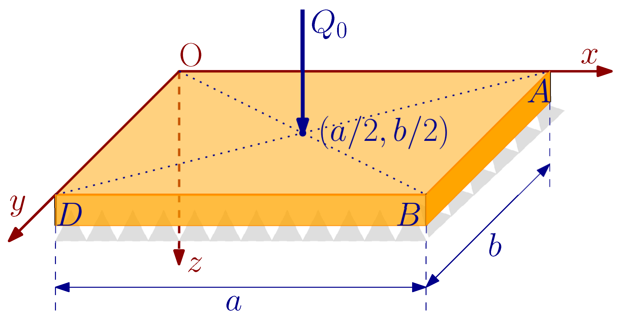
In this section, the example of a simply supported rectangular plate is illustrated, see Figure 4, in order to investigate the static bending and free vibration behavior of the gradient Mindlin–Reissner–type elastic plate developed in Section 4.5. The results are compared with the classical Mindlin and Kirchhoff plates, and the models reviewed from the literature in Section 6.
We consider a rectangular plate whose straight sides of length a and b are parallel to the axes x- and y-, respectively, of the Cartesian reference system O x y , Figure 4. The upper surface of the plate is loaded by a concentrated force Q 0 , at the point ( x , y ) = ( a / 2 , b / 2 ) . In the following subsections, the appropriate boundary conditions for the Mindlin–Reissner and Kirchhoff plate models M1, M2, K1, and K2 are illustrated.

7.1. Boundary Conditions for the Mindlin–Reissner Plate Model M1

For the boundaries referred to the sides D O ¯ and A B ¯ , with coordinates and normal vectors ( x , y ) D O ¯ = ( 0 , y ) , ( x , y ) A B ¯ = ( a , y ) , and n D O ¯ = 1 , 0 , n A B ¯ = + 1 , 0 , the following boundary conditions are considered, according to relations (55)–(57) of Section 4.5,
( b 2 ) ( i ) M 1 = 0 ( b 2 ) ( i i ) θ 2 = 0 ( c 2 ) w = 0 ( d 2 ) ( i ) θ 1 , 1 = 0 ( d 2 ) ( i i i ) n 1 m 112 = 0 ( d 2 ) ( v ) n 1 m 113 = 0
For the boundaries referred to the sides O A ¯ and B D ¯ , with coordinates and normal vectors ( x , y ) O A ¯ = ( x , 0 ) , ( x , y ) B D ¯ = ( x , b ) , and n O A ¯ = 0 , 1 , n A B ¯ = 0 , + 1 , respectively, the following boundary conditions are considered, according to relations (55)–(58) of Section 4.5,
( b 2 ) ( i ) θ 1 = 0 ( b 2 ) ( i i ) M 2 = 0 ( c 2 ) w = 0 ( d 2 ) ( i i ) n 2 m 212 = 0 ( d 2 ) ( i v ) θ 2 , 2 = 0 ( d 2 ) ( v i ) n 2 m 223 = 0
Finally, the jump conditions in Equation (58) at the four corners of the plate C O , C A , C B , C D read as follows:
θ 1 = 0 ; θ 2 = 0 ; w = 0

7.2. Boundary Conditions for the Kirchhoff Plate Model K1

For the boundaries referred to the sides D O ¯ and A B ¯ , with coordinates and normal vectors ( x , y ) D O ¯ = ( 0 , y ) , ( x , y ) A B ¯ = ( a , y ) , and n D O ¯ = 1 , 0 , n A B ¯ = + 1 , 0 , respectively, the following boundary conditions are considered, according to relations (78)–(80) of Section 5.5,
( b 4 ) w = 0 ( c 4 ) M 1 = 0 ( d 4 ) w , 11 = 0
For the boundaries referred to the sides O A ¯ and B D ¯ , with coordinates and normal vectors ( x , y ) O A ¯ = ( x , 0 ) , ( x , y ) B D ¯ = ( x , b ) , and n O A ¯ = 0 , 1 , n B D ¯ = 0 , + 1 , respectively, we have
( b 4 ) w = 0 ( c 4 ) M 2 = 0 ( d 4 ) w , 22 = 0
Finally, the jump conditions (81)–(83) at the four corners of the plate read as follows:
w = 0 ; w , 1 = 0 ; w , 2 = 0

7.3. Boundary Conditions for the Classical Mindlin–Reissner Plate Model M2

For the boundaries referred to the sides D O ¯ and A B ¯ , with coordinates and normal vectors ( x , y ) D O ¯ = ( 0 , y ) , ( x , y ) A B ¯ = ( a , y ) , and n D O ¯ = 1 , 0 , n A B ¯ = + 1 , 0 , respectively, we have
w = 0 ; θ 2 = 0 ; M 11 = 0
For the boundaries referred to the sides O A ¯ and B D ¯ , with coordinates and normal vectors ( x , y ) O A ¯ = ( x , 0 ) , ( x , y ) B D ¯ = ( x , b ) , and n O A ¯ = 0 , 1 , n B D ¯ = 0 , + 1 , respectively, we have
w = 0 ; θ 1 = 0 ; M 22 = 0

7.4. Boundary Conditions for the Classical Kirchhoff Plate Model K2

For the boundaries referred to the sides D O ¯ and A B ¯ , with coordinates and normal vectors ( x , y ) D O ¯ = ( 0 , y ) , ( x , y ) A B ¯ = ( a , y ) , and n D O ¯ = 1 , 0 , n A B ¯ = + 1 , 0 , respectively, there is
w = 0 ; M 11 = 0
For the boundaries referred to the sides O A ¯ and B D ¯ , with coordinates and normal vectors ( x , y ) O A ¯ = ( x , 0 ) , ( x , y ) B D ¯ = ( x , b ) , and n O A ¯ = 0 , 1 , n B D ¯ = 0 , + 1 , respectively, we have
w = 0 ; M 22 = 0

7.5. Static Bending Behavior for Mindlin–Reissner Plate Model M1

For the static bending problem the displacement and rotations are functions only of the coordinates ( x , y ) of the plate’s mid-plane w w ( x , y ) , θ 1 θ 1 ( x , y ) , θ 2 θ 2 ( x , y ) , and are expressed by the following double expanded trigonometric series,
w ( x , y ) = m = 1 n = 1 W m n sin m π x a sin n π y b θ 1 ( x , y ) = m = 1 n = 1 Θ m n x cos m π x a sin n π y b θ 2 ( x , y ) = m = 1 n = 1 Θ m n y sin m π x a cos n π y b
where the Fourier coefficients W m n , Θ m n x , Θ m n y are to be determined for every pair of the integers m and n. It is obvious that the boundary conditions stated previously in Section 7.1, Section 7.2, Section 7.3 and Section 7.4 are satisfied by the above trigonometric expansions. It should also be noted that Equations (105) satisfy the boundary conditions related to the plate models reviewed in Section 6 above. The interested reader should refer to the cited papers for more details.
Additionally, the vertical loading Q on the upper surface of the plate is expanded in a Fourier series as follows [50],
Q ( x , y ) = m = 1 n = 1 Q m n sin m π x a sin n π y b
where the Fourier coefficients Q m n are given by the relation.
Q m n = 4 Q 0 a b sin m π a sin n π b
Substituting Equations (105) and (106) into the equations of motion (52), the following system of linear algebraic equations is obtained,
[ C ] W m n Θ m n x Θ m n y T = Q m n 0 0 T
The solution of this system yields the relations of the Fourier coefficients W m n , Θ m n x , Θ m n y . Then, upon substitution into Equations (105) the exact solutions for the displacement w and the rotations θ 1 , θ 2 are obtained.
The components of the 3 × 3 matrix [ C ] are given as follows:
C 21 = C 12 C 22 = k s t G π a b 2 A B m 2 b 2 + A C n 2 a 2 I z g 2 π a b 4 λ 1 + 2 G m 4 b 4 + λ 1 + 3 G m 2 b 2 n 2 a 2 + G n 4 a 4 C 23 = m π a n π b A D + g 2 I z λ 1 + G A m n C 31 = C 13 C 32 = C 23 C 33 = k s t G π a b 2 A B n 2 a 2 + A C m 2 b 2 I z g 2 π a b 4 λ 1 + 2 G n 4 a 4 + λ 1 + 3 G m 2 b 2 n 2 a 2 + G m 4 b 4
where A m n = π a b 2 m 2 b 2 + n 2 a 2 .

7.6. Free Vibration Behavior for Mindlin–Reissner Plate Model M1

The displacement w and the rotations θ 1 , θ 2 are now considered to be functions of the time t, and the ( x , y ) coordinates of the plate’s mid-plane w w ( x , y , t ) , θ 1 θ 1 ( x , y , t ) , θ 2 θ 2 ( x , y , t ) . They are expressed by the following double series expansions:
w ( x , y , t ) = m = 1 n = 1 W m n sin m π x a sin n π y b e j ω m n t θ 1 ( x , y , t ) = m = 1 n = 1 Θ m n x cos m π x a sin n π y b e j ω m n t θ 2 ( x , y , t ) = m = 1 n = 1 Θ m n y sin m π x a cos n π y b e j ω m n t
where ω m n is the ( m n ) th natural frequency of vibration of the simply supported plate, and j the imaginary number, j 2 = 1 . It can easily be verified that the boundary conditions described in Section 7.1, Section 7.2, Section 7.3 and Section 7.4 are fully satisfied by Equation (110). Substituting Equation (110) into the governing equations of motion (52), the following system of algebraic equations is obtained,
[ C ] ρ ω m n 2 [ D ] W m n Θ m n x Θ m n y T = 0 0 0 T
where the components of the 3 × 3 matrix [ C ] are given by Equation (109), as in the static case (see Section 7.5), and the components of the 3 × 3 matrix [ D ] are given as follows,
D 11 = t 1 + h 2 3 A m n D 22 = I z + t h 2 3 I z h 2 3 A m n D 33 = D 22 D i j = 0 f o r i j
In order for Equation (111) to have non-trivial solutions for the Fourier coefficients W m n , Θ m n x , Θ m n y , the determinant of the system should be equal to zero,
det [ C ] ρ ω m n 2 [ D ] = 0
The three real and positive roots of Equation (113), ω m n ( i ) 2 , i = 1 , 2 , 3 , correspond to the frequencies associated with the three vibration modes of the Mindlin plate, i.e., one flexural mode, one thickness-shear mode at the x-z plane and one thickness-shear mode at the y-z plane [48,49,52]. The smallest one corresponds to the essential flexural mode. Nevertheless, as it is observed by Mindlin in [48], all three principal kinematical variables, w , θ 1 , θ 2 contribute to the composition of these three vibration modes.

7.7. Static Bending and Free Vibration Behavior for Kirchhoff Plate Model K1

In order to investigate the static bending and free vibration behavior of the gradient Kichhoff plate model K1, based on Equation (90) (see also Section 6.5 and Section 7.2), a similar procedure, as in Section 7.5 and Section 7.6, is followed. Thus, the flexural displacement w is expressed as a double series expansion on the ( x , y ) coordinates and the time t,
w K 1 ( x , y , t ) = m = 1 n = 1 W m n K 1 sin m π x a sin n π y b e j ω m n K 1 t
Substituting Equation (114) into Equation (90), the following equations are derived:
(1)
for the static bending problem the bending Fourier coefficients W m n K 1 are given as
W m n K 1 = Q m n D A m n 2 1 + 12 g 2 t 2 + g 2 A m n
(2)
while, for the free vibration problem the flexural fundamental frequencies ω m n K 1 are obtained,
ω m n K 1 = D A m n 2 1 + 12 g 2 t 2 + g 2 A m n ρ t + I z + 2 t h 2 3 A m n + I z h 2 3 A m n 2

8. Numerical Results and Comparison between Models

In this section, numerical results for the example in Section 7, are presented and discussed. The material of the plate is selected to be the same used in [37]. The numerical values for the material properties, the shear correction factor, the load Q and the dimensions of the plate are presented in the next Table 1.

8.1. Numerical Results for the Static Bending Problem

For the static bending behavior of the simply supported plate of Figure 4, we investigate the dependence of the deflection w and the rotation θ 1 on the microscopic parameter g (the strain gradient effect), the plate thickness t, and dimensions a , b .

8.1.1. Influence of Strain Gradient Effect on Thin Plates

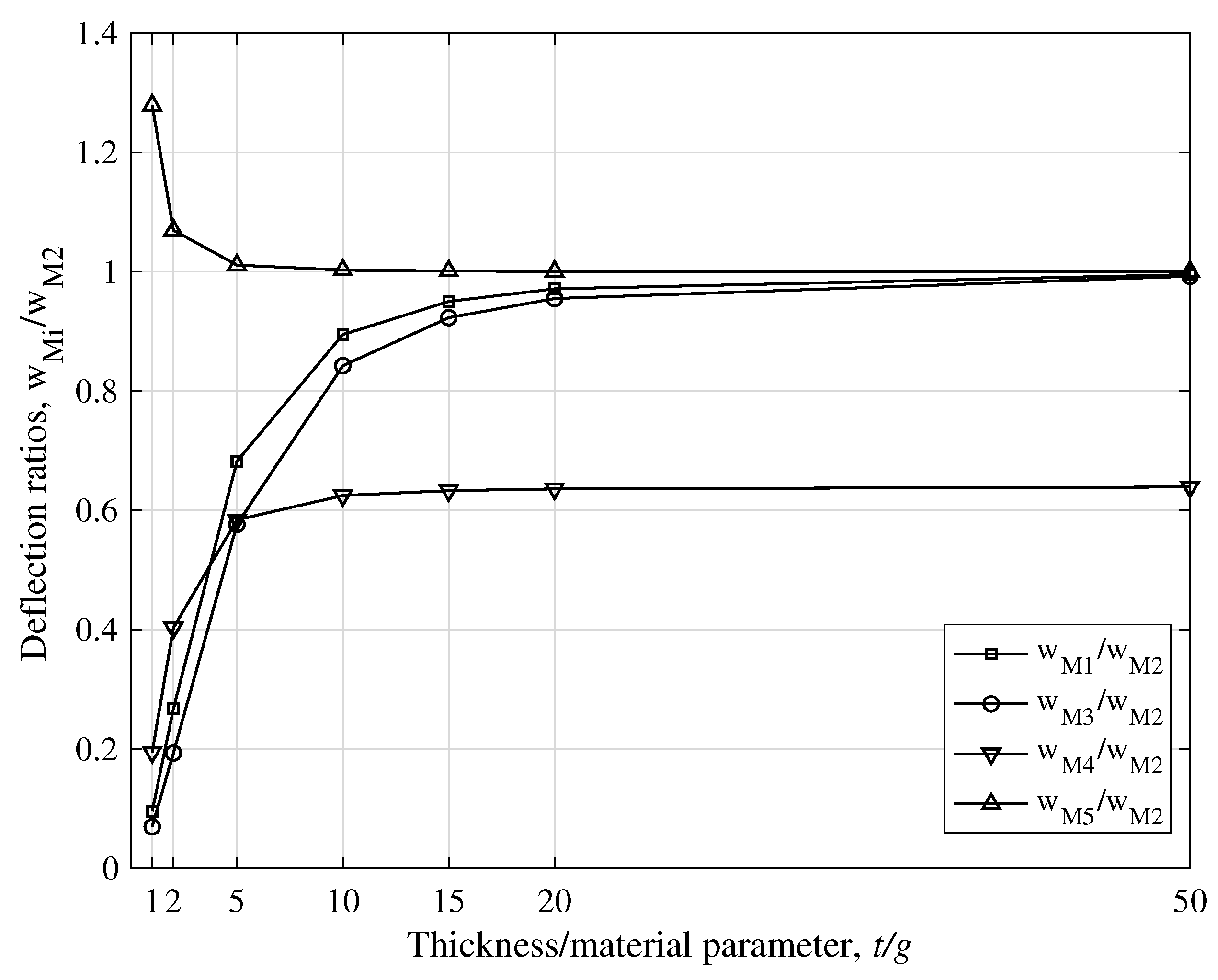
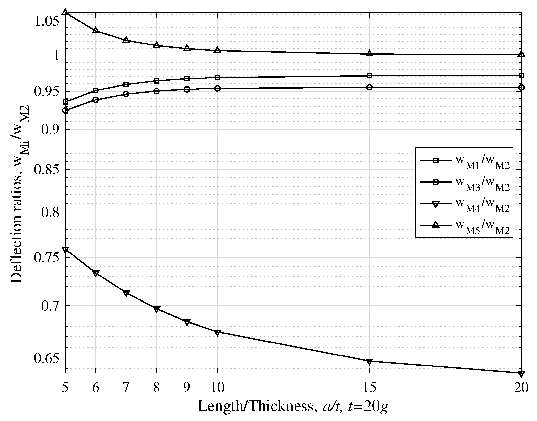
In Figure 5 and Figure 6, the deflection ratio w M i / w M 2 and rotation ratio θ 1 M i / θ 1 M 2 , respectively, for thin plates ( a = b = 20 t ) and for various values of the plate thickness t, are depicted for the Mindlin–Reissner–type plates. The deflection ratios w K i / w K 2 for the Kirchhoff-type plates are depicted in Figure 7. The notations Mi and Ki, for i = 1 , 3 , 4 , 5 stand for the classification of the plate models as presented in previous Section 6.
It is obvious that the deflections of model M1 are smaller than those of model M2, while the difference diminishes for increasing values of the plate thickness with respect to the material microstructure parameter g i.e., the ratio t / g . This means that the strain gradient effect is mostly important for cases where the thickness of the plate is at the micron scale. Similar results were also observed in the works of [37,43], as can easily be verified by Figure 5. The gradient and couple-stress models are much stiffer than the classical ones, both for Mindlin–Reissner–type and Kirchhoff-type plates, a result also observed by the authors of the respective models. By contrast, the nonlocal plate models M5 and K5 are softer than their classical counterparts, models M2 and K2, respectively [35]. Note that model M4, as developed in [37] based on a modified couple-stress theory (see Section 6.3 above), does not converge to the classical Mindlin plate theory with increasing ratio t / g . The same observations hold true for the rotation ratios, Figure 6. The behavior of rotation θ 2 is not depicted in a figure due to similarity with θ 1 .
Considering the deflection ratios for Kirchhoff plates, the same observations made for the Mindlin plates hold true. For thin plates the strain gradient effect should not be ignored for small values of the ratio t / g , Figure 7. It is also observed that models K1 (current) and K4 (Tsiatas’s couple-stress plate model) are much stiffer than models K3 (Papargyri-Beskou’s gradient model) and K5 (nonlocal model). Moreover, models K1 and K4 converge to the classical Kirchhoff plate theory, model K2, with lower rate than do models K3 and K5, at increasing ratio t / g .
Next, we are going to show the differences between models M1 (current developed gradient model) and M3 (Ramezani’s gradient model). The deflection and rotation ratios for the two models are depicted in Figure 8a,b, respectively, for thin simply supported rectangular plates and for various values of the ratio t / g . It is obvious that model M1 is less stiff than model M3, both for deflection and rotations. This difference is due to the different plane stress assumptions used in the two models, see Section 2 and Section 6.2. It is also observed that as the plate thickness increases with respect to g, i.e., for increasing values of the ratio t / g , the two models converge.

8.1.2. Influence of Strain Gradient Effect on Thick Plates

The sensitivity of the plate deflection on the length-to-thickness ratio a / t , has been investigated in [43], and the same observations hold true for the gradient model M1 developed herein. In Figure 9 and Figure 10, for t / g equal to 1 and 20, respectively, the deflection ratios are depicted for thick plates, ( a / t ) [ 5 , 20 ] . It is observed that as long as the plate thickness t is at the micron scale, i.e., comparable to the microstructure parameter g, the deflection ratios for models M1, M3, and M4 exhibit very small values, Figure 9a. On the other hand, for larger values of the ratio t / g , e.g., 20, the deflection ratio is closer to unity even for thick plates, although the strain gradient effect has not been diminished completely, see Figure 10. These observations indicate the significance of the strain gradient effect on the static bending behavior of thick plates. It is also interesting to indicate the peculiar behavior of models M4 and M5. For the nonlocal model M5 and for t g we observe an extremely noticeable difference with the classical model M2, especially for thick plates, Figure 9b. For the couple-stress model M4, we observe a constant deviation from its classical counterpart M2 (Figure 10), meaning that the strain gradient effect influences the bending behavior in any case, i.e., for thin and thick plates, and for any value of the ratio t / g . This last observation may be interpreted by the fact that model M4 do not reduce to model M2 when the microscopic parameter g becomes zero, see Section 6.3.
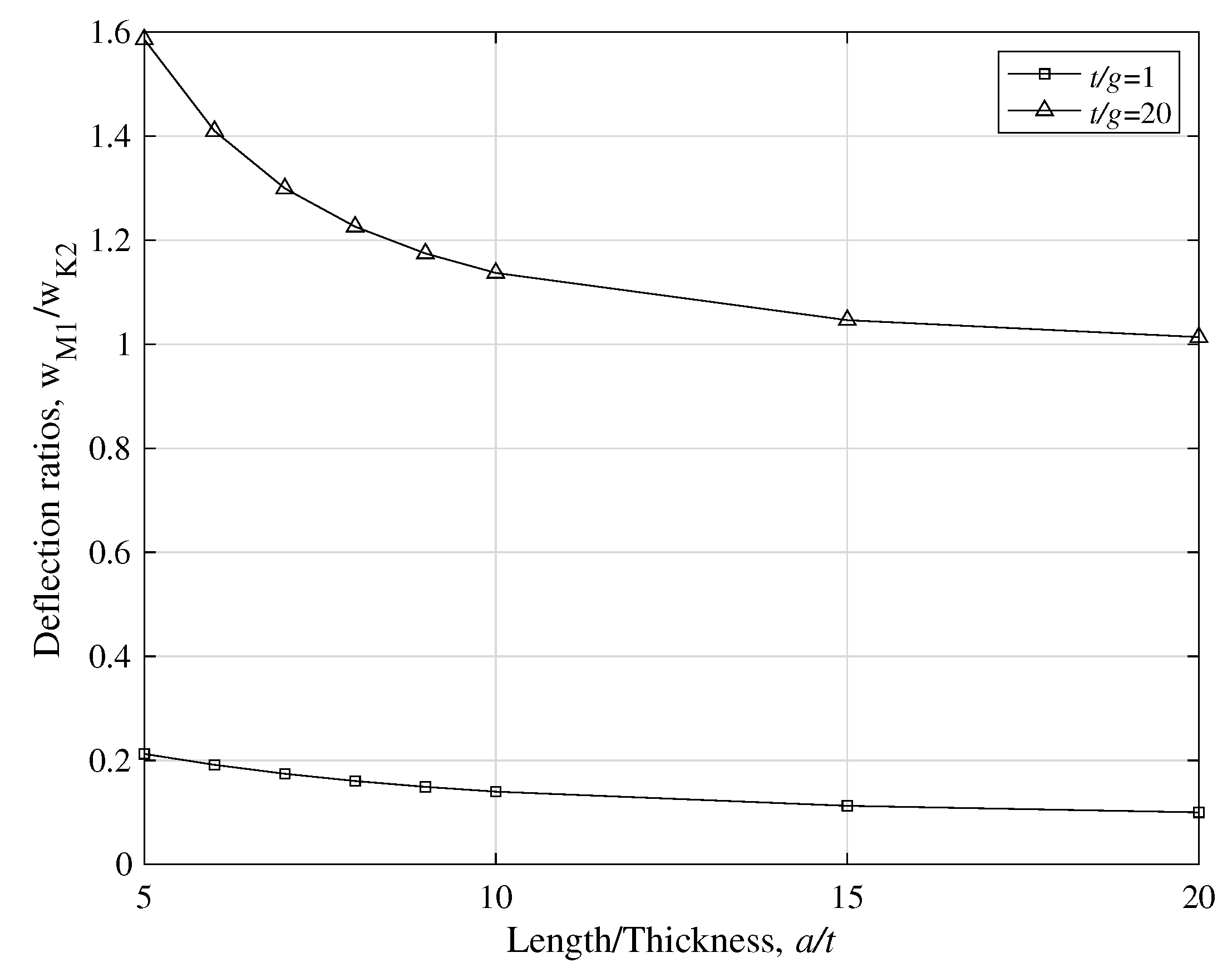
It would also be interesting to investigate the influence of the strain gradient effect on the deflection ratio between models M1 and K2, i.e., with respect to the classical Kirchhoff plate theory. To this end, the deflection ratio w M 1 / w K 2 is depicted in Figure 11, varying with the length-to-thickness ratio a / t , for t / g equal to 1 and 20. For thick plates, i.e., 5 < a / t < 10 , the deflection predicted by model M1 deviates significantly from that predicted by K2, both for small and large values of the ratio t / g . As ratio a / t increases, i.e., for thinner plates, model M1 converges to K2 for larger values of the ratio t / g , indicating thus the attenuation of the strain gradient effect. However, for plate thickness at the micron scale, e.g., t / g = 1 , the strain-gradient effect seems to play a significant role in the bending behavior of the plate, both for thick and thin plates.

8.2. Free Vibration Problem

In this section, the free vibration problem is investigated. In particular, the dependence of the fundamental frequencies ω 1 ω 11 (flexural for Mindlin–Reissner and Kirchhoff plate models) and ω x z ω 11 x z (thickness-shear mode for Mindlin–Reissner plates) on the ratios t / g , and a / t is examined. The influence of the micro-inertia effect is also addressed for models M1 and K1.

8.2.1. Natural Frequencies for Mindlin–Reissner Type Plate Models

In Figure 12, the fundamental flexural frequency ω 1 varying with the ratio t / g is depicted. The figure shows all Mindlin–Reissner models presented in previous Section 6, for comparison reasons. Note that the frequency predicted by model M1, the gradient Mindlin plate developed herein, is lower than the one predicted by model M3 in [43] (see Section 2 and Section 6.2 and the discussion of Figure 8).
In Figure 13, the ratios ω 1 M i / ω 1 M 2 of the natural flexural frequency are depicted varying with the ratio t / g . It is noteworthy that for the models M1, M3, and M4, the frequency is always higher than the one predicted by the classical Mindlin plate theory, while the nonlocal model M5 underestimates the frequency. Furthermore, as the plate thickness increases with respect to the microstructure material parameter g, all frequencies—except from model M4—converge to the value of the classical theory. It is thus apparent the significance of the strain gradient effect at the micron scale, when t g . The deviation of model M4 from M2 is due to the fact that M4 does not reduce to M2 for decreasing values of the microscopic parameter g (see also Section 6.3, Section 8.1.1 and Section 8.1.2).
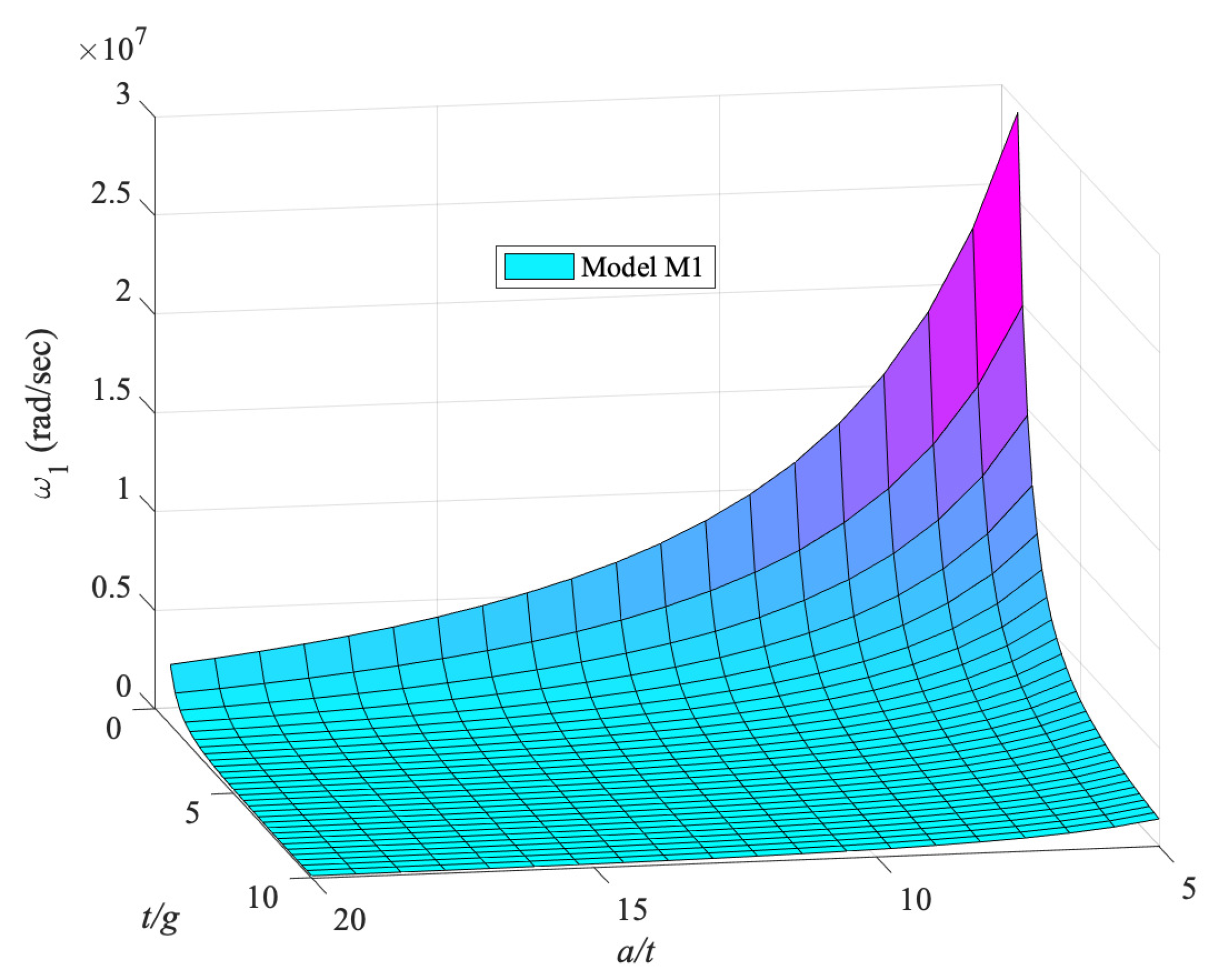
Next, in Figure 14, a 3D plot for the first natural flexural frequency ω 1 for model M1 is depicted as a function of the ratios a / t and t / g . Furthermore, note that the thinner the plate, i.e., for increasing ratio a / t , the lower the fundamental frequency. Moreover, the smaller the ratio t / g , i.e., for plate thickness comparable to the material parameter g, the higher the frequency becomes, especially for thick plates, i.e., small ratio a / t .
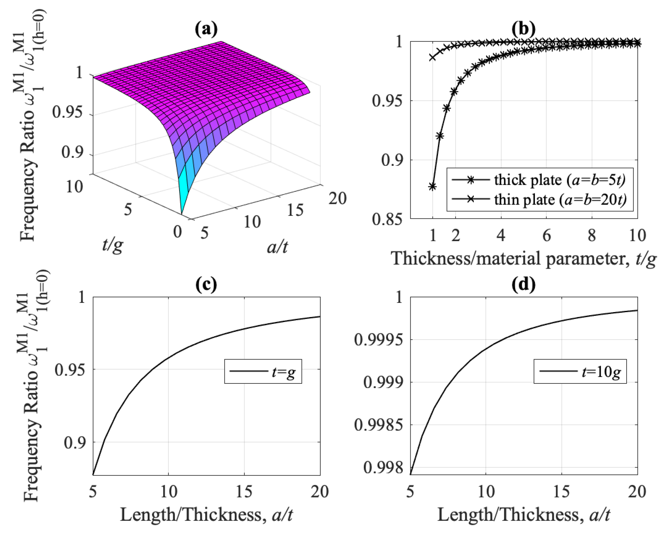
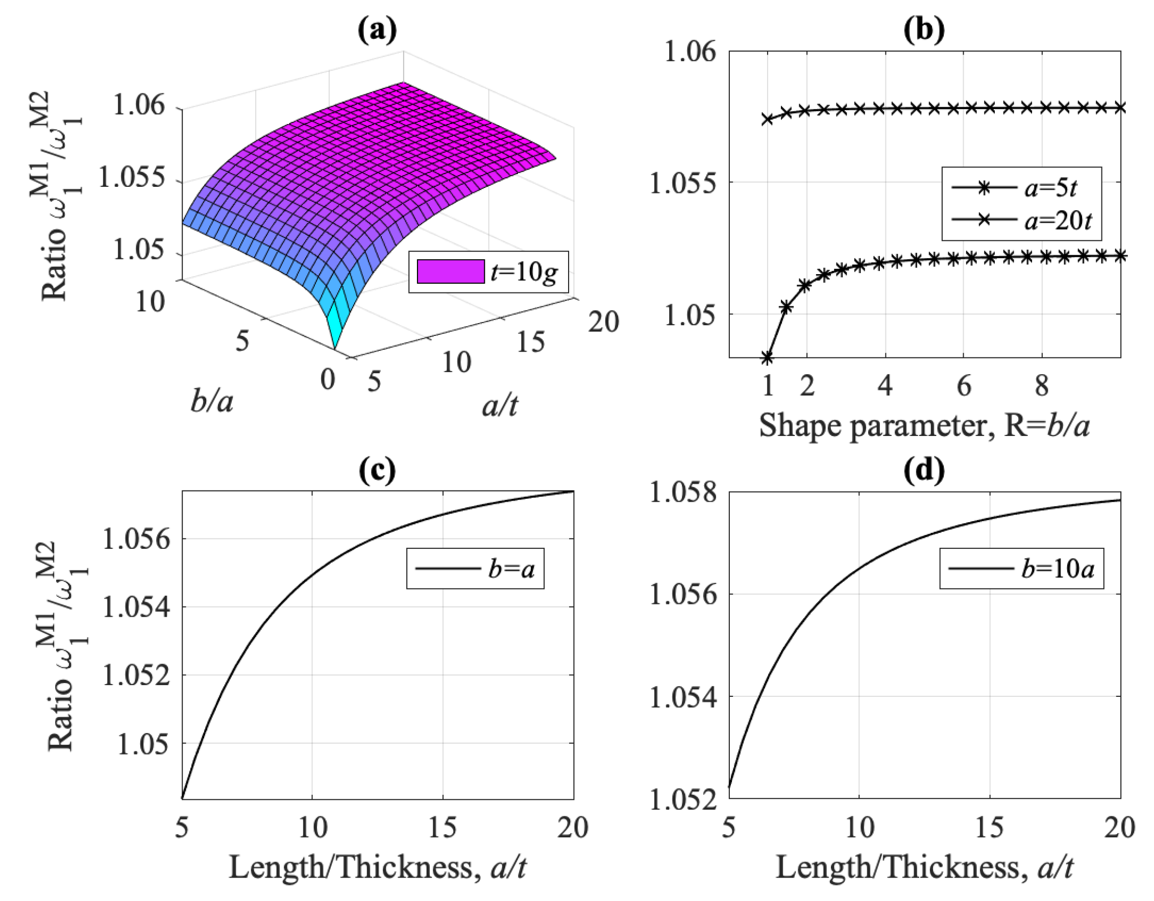
The ratio ω 1 M 1 / ω 1 M 2 of the fundamental flexural frequencies for models M1 and M2 is depicted in Figure 15. It is noteworthy that the frequency predicted by model M1 with microstructure considerations is always higher than that of the classical Mindlin plate, model M2. As it can be observed, the thicker the plate, e.g., small ratio a / t , the lower the fundamental frequency ratio ω 1 M 1 / ω 1 M 2 , Figure 15c,d. Also, as the plate thickness increases with respect to material microstructure parameter g, (increasing t / g ), the ratio ω 1 M 1 / ω 1 M 2 converges to unity, both for thick and thin plates. These last observations are illustrated more clearly in Figure 15b–d, as parts of the 3D Figure 15a.
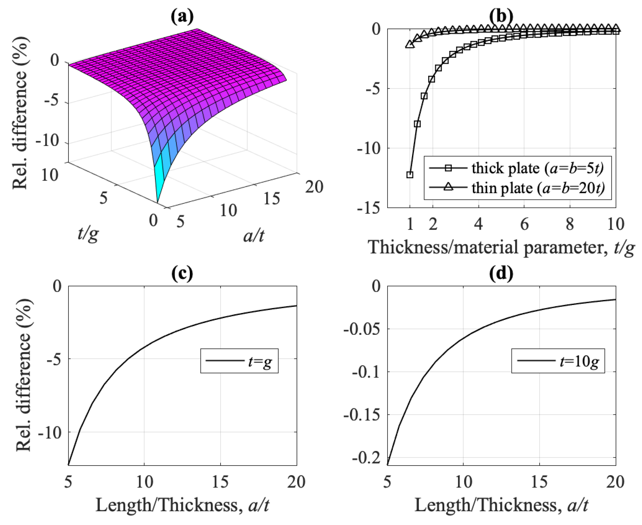
Now we are going to investigate the influence of micro-inertia terms, reflected on material parameter h, in the dynamic behavior of the simply supported rectangular plate. To this end, refer first to Figure 16, where the ratio of fundamental flexural frequencies for model M1 with ( h = g ) and without ( h = 0 ) micro-inertia terms is depicted, as function of the ratios a / t and t / g . Note that the thinner the plate (i.e., larger ratio a / t ) the closer the values of the fundamental frequencies predicted by model M1 with and without micro-inertia terms. Furthermore, for higher values for the ratio t / g , the effect of the micro-inertia terms renders insignificant and the predicted frequencies almost coincide, both for thick and thin plates. This can be readily verified in Figure 17, where the relative difference between the two frequencies is depicted. For plate thickness t at the micron scale, i.e., for small ratios t / g , the relative difference can be as much as 12% for thick plates ( a / t = 5 ) and 2% for thin plates ( a / t = 20 ) , Figure 17b.
Next, we investigate the fundamental flexural frequency as a function of the plate dimensions, i.e., the ratios b / a and a / t . First, the ratio ω 1 M 1 / ω 1 M 2 is depicted for t = g in Figure 18, and for t = 10 g in Figure 19. The significance of the strain gradient effect is apparent, as, for plate thickness at the micron scale, i.e., for t = g , the frequency calculated by model M1 is much greater than M2, and increases with increasing ratio a / t , no matter the values of ratio b / a (compare Figure 18c,d and Figure 19c,d). Furthermore, as the shape ratio b / a increases, the frequency ratio converges to a single value depending on the ratio a / t , Figure 18b and Figure 19b.
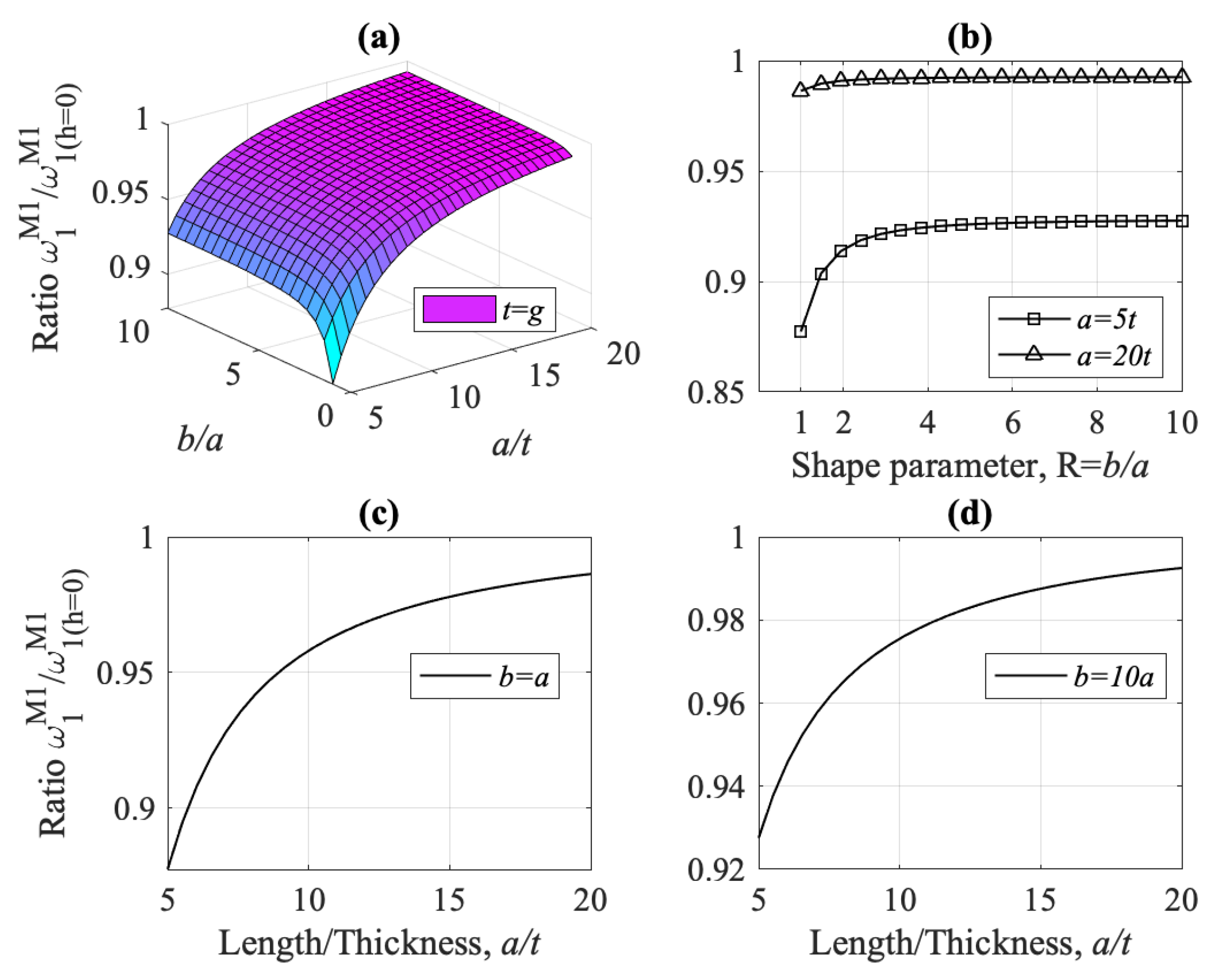
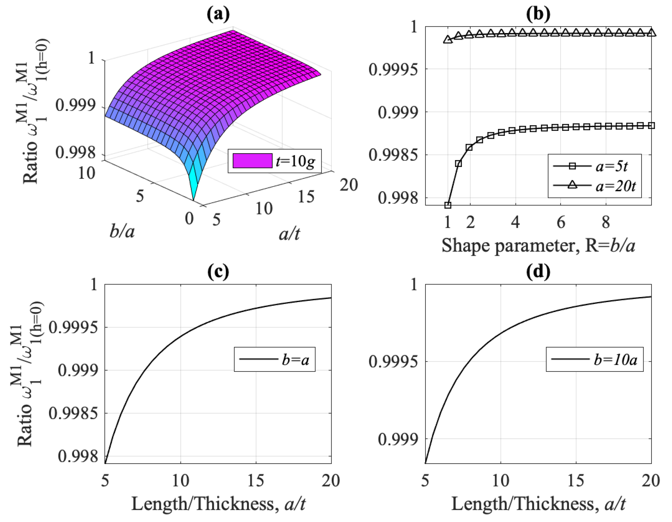
A similar behavior is observed for the fundamental flexural frequency ratio ω 1 M 1 / ω 1 ( h = 0 ) M 1 with and without micro-inertia terms, for t = g in Figure 20 and for t = 10 g in Figure 21. Note that this behavior is different from that observed in Figure 16, where the frequency ratio ω 1 M 1 / ω 1 ( h = 0 ) M 1 is depicted as a function of the ratios a / t and t / g . From Figure 20 it is deduced that for t = g and small a / t ratios, i.e., for thick plates, the two frequencies, with and without micro-inertia terms, differ from each other, even for large values of the shape ratio b / a . However, for greater ratios t / g , e.g., t = 10 g , these differences become insignificant, especially for increasing ratios b / a and a / t , indicating once again that the strain gradient effect is only effective when the plate thickness t is at the micron scale, compare Figure 20 with Figure 21.
Finally, we investigate briefly the fundamental frequencies for the other two vibration modes of the Mindlin–Reissner-type plates, i.e., the frequencies ω x z and ω y z , for the shear-thickness modes at the x-z and y-z planes, respectively. It is noted that the values of these frequencies are much greater than the fundamental flexural frequency investigated so far.
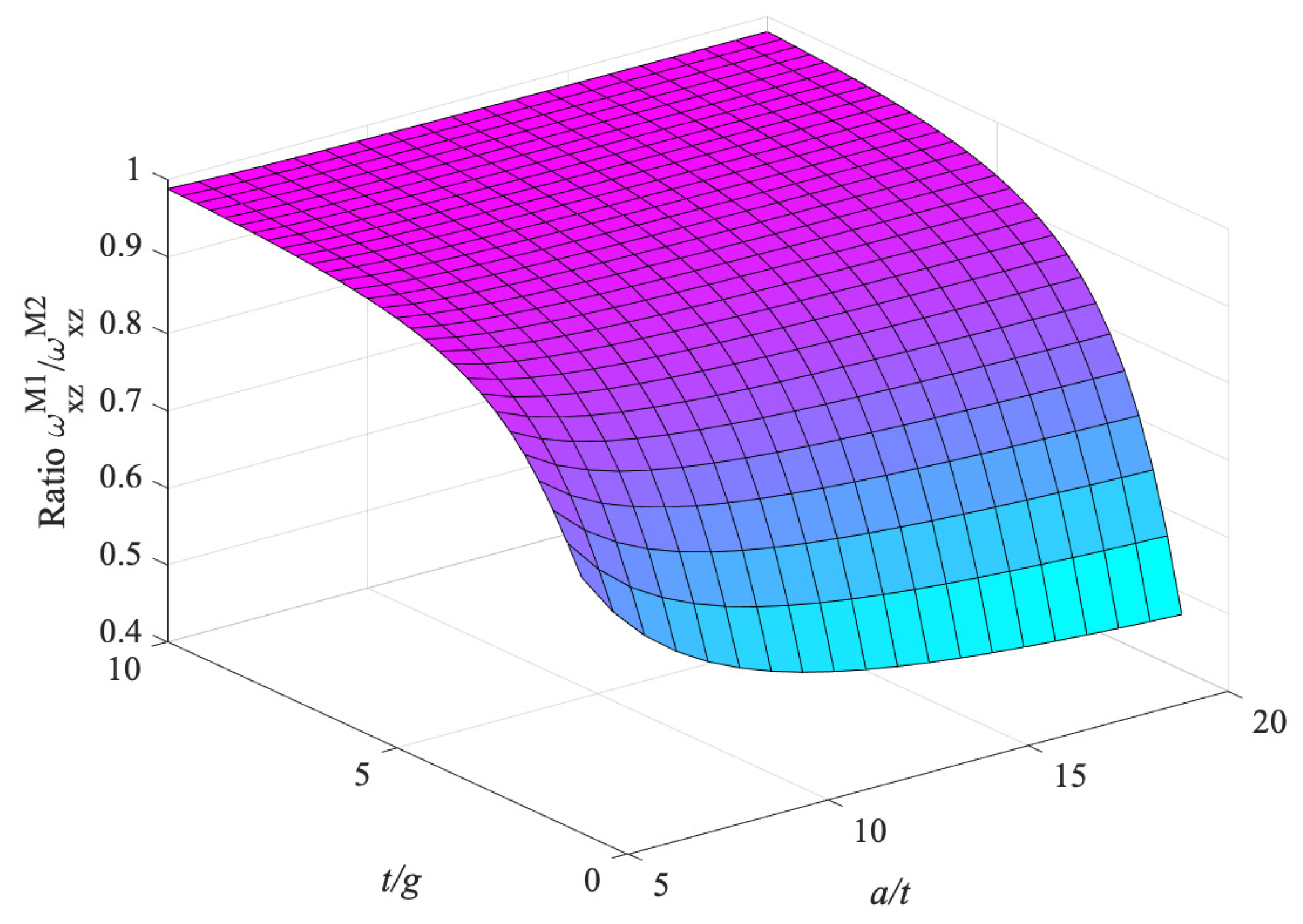
In Figure 22, the ratio ω x z M 1 / ω x z M 2 of the fundamental shear-thickness frequency ω x z is depicted as a function of the ratios a / t and t / g . The strain gradient effect is mostly significant for plates with thickness at the micron scale, i.e., for small ratios t / g , both for thin and thick plates, i.e., 5 < a / t < 20 . On the other hand, this effect diminishes for increasing ratio t / g .
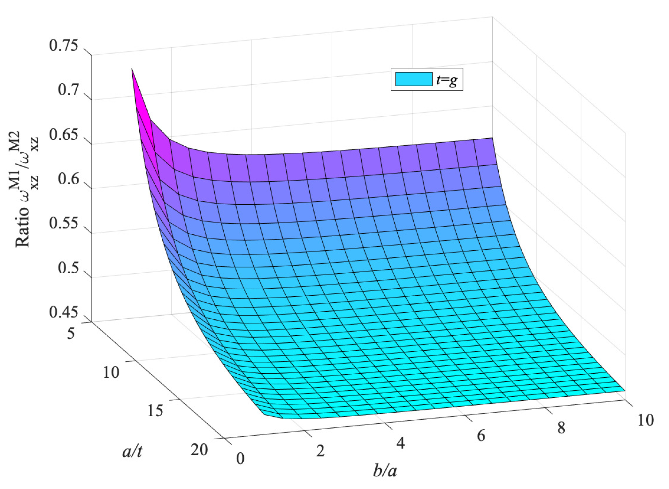
In Figure 23, the same frequency ratio ω x z M 1 / ω x z M 2 is depicted varying with the ratios a / t and b / a , for t = g . The strain gradient effect is more significant here, as model’s M1 shear thickness frequency ω x z deviates from its counterpart model M2, both for thick and thin plates, ratio a / t , and for every value of the shape ratio b / a . However, for plate thickness much greater than the microscopic parameter g, e.g., t = 10 g , the strain gradient effect attenuates significantly, (not pictured here).
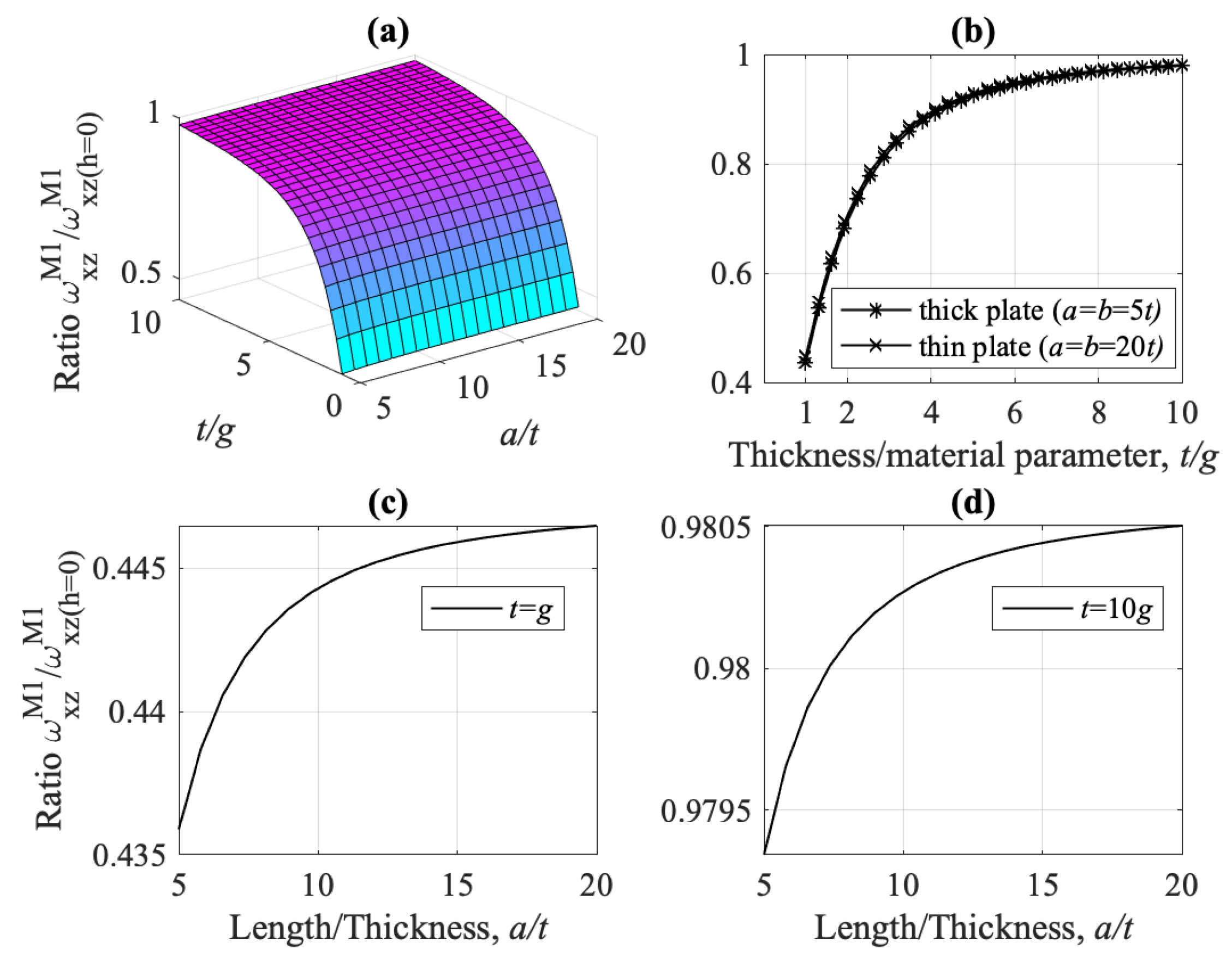
Last, considering the micro-inertia effect (term h), we observe from Figure 24 that this effect should not be ignored, especially for small ratios t / g (see Figure 24c). For greater values, e.g., t = 10 g , the micro-inertia effect does not play any significant role (see Figure 24d). The behavior of the frequency ω y z for the shear-thickness mode at the y-z plane is analogous to the behavior of ω x z and the same observations hold true.

8.2.2. Natural Frequencies for Kirchhoff Type Plate Models

The behavior of the fundamental flexural frequency ω 1 for the gradient Kirchhoff type plate, model K1, is similar to the behavior of model M1. For completeness we will present in short only some results. In Figure 25, the frequency ratio ω 1 K 1 / ω 1 K 2 is depicted as a function of the ratio t / g , for thin plates ( a = b = 20 t ) . It is noteworthy that for models K1, K3, and K4, the frequency is always higher than the one predicted by the classical Kirchhoff plate theory, model K2, while the nonlocal model K5 underestimates the frequency.
Finally, the same observations as for model M1 for the effect of the micro-inertia terms hold true for model K1. In Figure 26 the ratio of the fundamental flexural frequency with and without micro-inertia terms is depicted as function of the ratios t / g and a / t . It is indicated that its effect is mostly significant for thick plates (small ratio a / t ) and for plate thickness t at the micron scale ( t g ) .

8.2.3. Comparison of Natural Frequencies between Mindlin-Type (M1) and Kirchhoff-Type (K1) Plate Models

Last, a comparison of the natural frequency ω 1 between models M1 (Mindlin-type) and K1 (Kirchhoff-type) is discussed in this subsection. The frequency ratio ω 1 M 1 / ω 1 K 1 is shown in Figure 27a for varying ratio t / g , for thin ( a / t = 20 ) and thick ( a / t = 5 ) plates, both for h = g and h = 0 . The strain gradient effect, ( g ) , is highly dominant in thick plates for plate thickness at the micron scale ( t g ) , although it is not diminished as t / g increases, Figure 27a. The micro-inertia term h contributes significantly only for thick plates and for plate thickness at the micron scale ( t g ) .
The effect of plate thickness a / t on the frequency ratio ω 1 M 1 / ω 1 K 1 is shown in Figure 27b with ( h = g ) and without micro-inertia effect ( h = 0 ) , for t = g and t = 10 g . When the plate thickness is comparable to the strain gradient parameter, t g , the two frequencies ω 1 M 1 and ω 1 K 1 differ significantly for thick plates, although the difference is still prominent for thin plates (increasing a / t ). For t = 10 g the difference between ω 1 M 1 and ω 1 K 1 is higher for thick plates, but still much smaller than the case of t g . The micro-inertia term h has insignificant influence on the frequency ratio ω 1 M 1 / ω 1 K 1 for t = 10 g , independent of the plate thickness a / t . However, it contributes significantly for t g and small values of the ratio a / t .

9. Summary and Conclusions

The aim of this contribution was to develop dynamic micro-plate models in order to investigate the influence of the strain gradient and micro-inertia effects on the static bending and free vibration behavior of micro-plates, based on Mindlin’s form-II first strain gradient elasticity theory. To this end, the plane stress assumption, expressed by the vanishing of the z-component of the true traction, was first considered in order to formulate the necessary constitutive relations. Then, using the general virtual work principle, the governing dynamic equations of motion and the detailed structure of classical and non-classical boundary conditions for a dynamic Mindlin–Reissner-type micro-plate (model M1) were obtained. Upon appropriate manipulations, model M1 was reduced to a Kirchhoff-type micro-plate, model K1. A short review of published micro-plate models (M3, M4, and M5 for Mindlin–Reissner plates and K3, K4, and K5 for Kirchhoff plates) based on various non-classical, higher-order continuum theories were presented, in order to compare with models M1 and K1 developed herein and with the classical Mindlin–Reissner and Kirchhoff plates, models M2 and K2, respectively. In order to investigate the static bending and free vibration behavior of models M1 and K1, an example of a simply supported rectangular plate was illustrated. The most interesting results are summarized as follows.

9.1. Conclusions for Static Bending Response of Micro-Plates

  • The strain gradient effect is proved to be more significant when the plate thickness t is at the micron-scale. That said, for small ratios t / g , models M1 and K1 are much stiffer than their classical counterparts, models M2 and K2, respectively, i.e., the deflection and the rotations are smaller than those predicted by models M2 and K2. These observations hold true for thick and thin plates, i.e., for every value of the ratio a / t .
  • Considering models M1 (present) and M3 (Ramezani’s), which were based on different plane stress assumptions (see Section 2 and Section 6.2), it is observed from Figure 8 that M1 is less stiff than M3, especially for small ratios t / g . The two models converge for increasing values of the ratio t / g .
  • Considering models M1 and K2, and Figure 11, the combined influence of the shear effect (characteristic of Mindlin–Reissner plates) and the strain gradient effect was investigated. For small ratios t / g and in every range of ratio a / t (i.e. for thick and thin plates), this combination is dominant and the two models deviate significantly from each other. For larger values of t / g , the difference between the two models is important only for thick plates, while for thin plates ( a / t = 20 or more) the two models converge, showing that the shear effect and the strain gradient effect diminish.
  • For plate thickness t is at the micron-scale (small ratio t / g ), models M1, M3 and M4 are stiffer than the classical model M2, while the non-local model M5 is softer than M2. The strain gradient effect is significant both for thick and thin plates, Figure 5, Figure 6, Figure 9 and 10. The same is true for their Kirchhoff counterparts; K1, K3 and K4 are stiffer than K2, while K5 is softer than K2, Figure 7 and Figure 11.
  • For larger values of the ratio t / g , models M1, M3 and M5 converge to the classical model M2 for increasing a / t , i.e., for thinner plates. The effect of strain gradient is not completely diminished for thick plates. Additionally, M1 converges to K2 for increasing a / t .

9.2. Conclusions for Free Vibration Response of Micro-Plates

It is reminded that there are three vibration modes for Mindlin–Reissner-type plates; one flexural mode and two shear-thickness modes (see Section 7.6), and one flexural mode for Kirchhoff-type plates.
  • The flexural fundamental frequency ω 1 for model M1 is always higher than that of model M2, for every value of the ratios t / g , a / t and b / a , i.e., for thick, thin, square and non-square plates, (see Figure 13, Figure 15, Figure 18 and Figure 19). Shear-thickness frequencies ω x z and ω y z are, respectively, always lower than those of model M2, for every value of the ratios t / g , a / t and b / a (see Figure 22 and Figure 23).
  • The strain gradient effect g is mostly significant when plate thickness is at the micron-scale, i.e., for small ratio t / g , both for thick and thin plates, and results in higher values for ω 1 and lower values for ω x z (as compared to model M2). For increasing ratios t / g , frequencies ω 1 and ω x z converge to their classical counterparts, (see Figure 15a and Figure 22, respectively).
  • The micro-inertia effect (reflected on parameter h), should not be omitted in estimating ω 1 , for plate thickness at the micron scale, i.e. for small ratio t / g , and for thick plates, i.e. for small ratio a / t , The difference could be as much as 12% for thick plates, (see Figure 16 and Figure 17).
  • Micro-inertia effect is also significant for the shear-thickness frequency ω x z , primarily when the plate thickness is at the micron scale (small ratio t / g ). At any range of the ratio t / g , the frequency ω x z is not greatly affected by the ratio a / t , Figure 24.
  • For the Kirchhoff-type model K1, the influence of the strain gradient effect, g, and the micro-inertia effect, h, on the fundamental flexural frequency ω 1 K 1 , is similar to that of ω 1 for model M1, and the same observations hold true (see Figure 25 and Figure 26).
  • Considering models M1 and K1, and Figure 27, the combined influence of the shear effect (characteristic of Mindlin–Reissner plates) and the micro-inertia effect, h, on the fundamental frequency ω 1 was investigated. Model M1 predicts always a smaller frequency ω 1 than K1. For thick plates, where the shear stresses cannot be ignored, the two models differ significantly, especially for lower values of the ratio t / g . The micro-inertial effect, h, contributes to the difference mostly for thick plates and for lower values of the ratio t / g . For thin plates, the micro-inertial term does not add to the difference in ω 1 predicted by the two gradient models M1 and K1. For thin plates (increasing a / t ) and when the plate thickness is much larger than the strain gradient parameter g, the two models give similar predictions for ω 1 .
  • For plate thickness t is at the micron-scale (small ratio t / g ), models M1, M3, and M4 overestimate the fundamental frequency ω 1 , as compared to the classical model M2, while model M5 underestimates it, Figure 13. Except model M4, all other models converge to M2 for increasing t / g .

Author Contributions

Conceptualization, S.M.; methodology, S.M. and D.F.; software, D.F.; validation, S.M. and D.F.; formal analysis, S.M. and D.F.; writing—original draft preparation, D.F.; writing—review and editing, D.F.; visualization, D.F. Both authors have read and agreed to the published version of the manuscript.

Funding

This research received no external funding.

Institutional Review Board Statement

Not applicable.

Informed Consent Statement

Not applicable.

Data Availability Statement

Not applicable.

Conflicts of Interest

The authors declare no conflict of interest.

Appendix A

The physical demonstration of most of the zero and non-zero components of the double stress tensor introduced in Section 2 is graphically depicted in Figure A1, Figure A2, Figure A3, Figure A4 and Figure A5, using the following nomenclature.
  • i denotes the normal to the face on which the double stress acts. For example, μ 1 j k acts on the faces (planes) that are normal to the x-axis (1-axis)
  • j, direction of the double stress arm. For example, the arm of μ i 2 k is along the y-axis (2-axis). The side of the arm which is towards the positive direction of the respective axis is termed as positive arm-side (is marked by a ball-point).
  • k, for positive double stress, acting on a positive face, the force on the ball-point (positive arm-side) is towards the positive k-axis (and the other force in the opposite direction).
  • For positive double stress, acting on a negative face, the force on the ball-point (positive arm-side) is towards the negative k-axis (and the other force in the opposite direction).
  • Positive face: the one which has outer normal towards the positive direction of an axis (1, 2 or 3)
  • Negative face: the one which has outer normal towards the negative direction of an axis (1, 2 or 3)
  • Note that, at each face of the elementary volume, the total (resultant) moment of the double stresses acting on that face is zero. In other words, the double stress system in strain gradient elasticity is in self-equilibrium at each face.
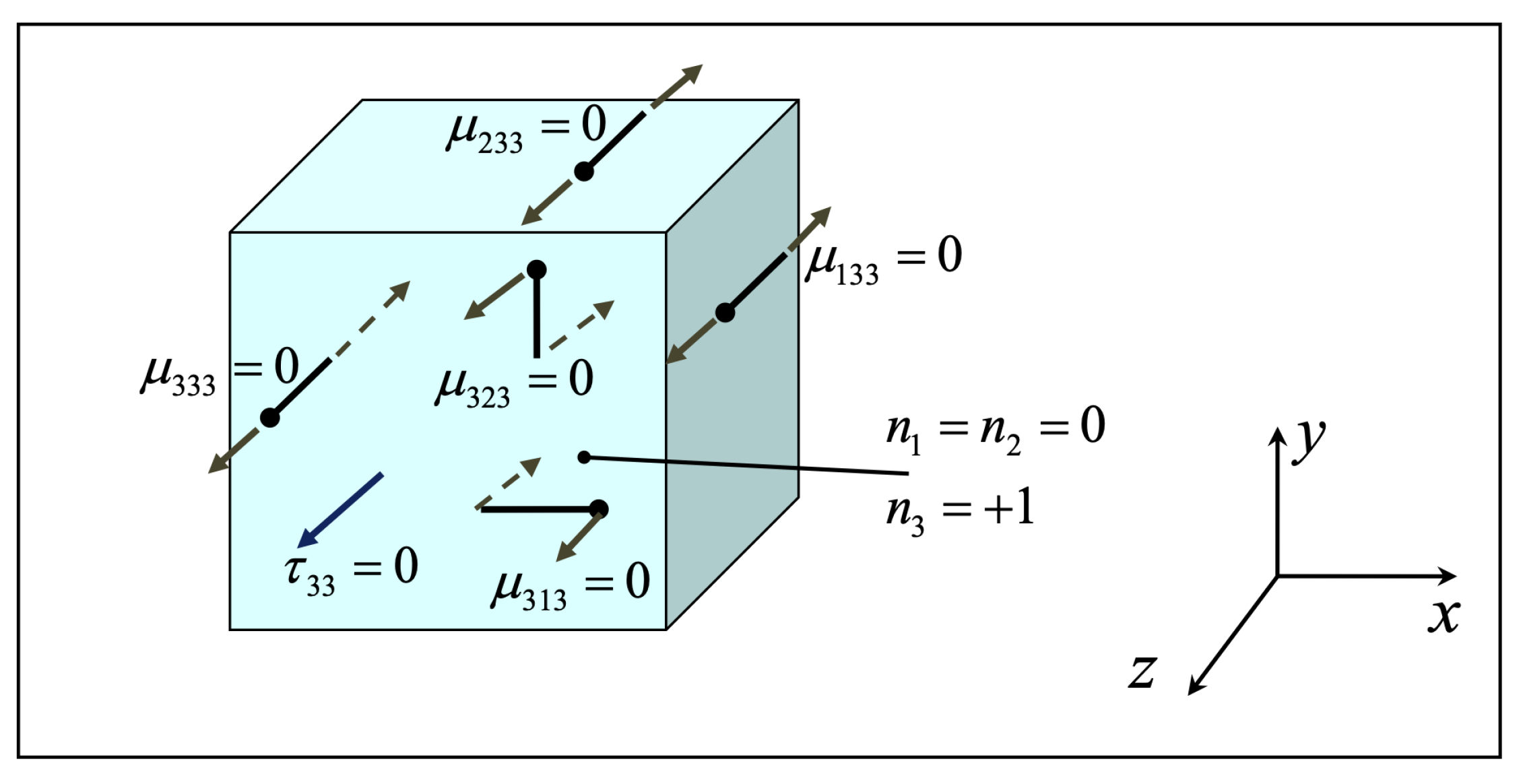
Figure A1. Zero-stress components resulting from the assumption of vanishing the true traction normal to the plate surface, along z direction.
Dynamics 01 00005 g0a1
Figure A2. Plane stress conditions on x-y plane; 2D strain gradient elasticity (FORM II); eight in-plane double stress components; double stress components of the form μ α β γ , α β γ = 1 , 2 , β γ (components on both positive and negative faces are shown).
Dynamics 01 00005 g0a2
Figure A3. Plane stress conditions on x-y plane; 2D strain gradient elasticity (FORM II); eight in-plane double stress components; double stress components of the form μ α β γ , α β γ = 1 , 2 , β = γ (components on both positive and negative faces are shown).
Dynamics 01 00005 g0a3
Figure A4. Plane stress conditions on x-y plane; 2D strain gradient elasticity (FORM II); eight out-of-plane double stress components; double stress components of the form μ α β 3 , μ α 3 β , α = 1 , 2 , β = 1 (components on both positive and negative faces are shown).
Dynamics 01 00005 g0a4
Figure A5. Plane stress conditions on x-y plane; 2D strain gradient elasticity (FORM II); four out-of-plane double stress components; double stress components of the form μ 3 α α , α = 1 , 2 (components on both positive and negative faces are shown).
Dynamics 01 00005 g0a5

References

  1. Senturia, S. Microsystem Design; Kluwer Academic Publishers: Boston, MA, USA, 2001. [Google Scholar]
  2. Reddy, J. Nonlocal nonlinear formulations for bending of classical and shear deformation theories of beams and plates. Int. J. Eng. Sci. 2010, 48, 1507–1518. [Google Scholar] [CrossRef]
  3. Zhang, H.; Sun, C. Nanoplate model for platelike nanomaterials. AIAA J. 2004, 42, 2002–2009. [Google Scholar] [CrossRef]
  4. Giannakopoulos, A.; Stamoulis, K. Structural analysis of gradient elastic components. Int. J. Solids Struct. 2007, 44, 3440–3451. [Google Scholar] [CrossRef] [Green Version]
  5. Mirjavadi, S.S.; Afshari, B.M.; Barati, M.R.; Hamouda, A. Transient response of porous FG nanoplates subjected to various pulse loads based on nonlocal stress-strain gradient theory. Eur. J. Mech. A/Solids 2019, 74, 210–220. [Google Scholar] [CrossRef]
  6. Ebrahimi, F.; Barati, M.R.; Dabbagh, A. A nonlocal strain gradient theory for wave propagation analysis in temperature-dependent inhomogeneous nanoplates. Int. J. Eng. Sci. 2016, 107, 169–182. [Google Scholar] [CrossRef]
  7. Fleck, N.; Muller, G.; Ashby, M.; Hutchinson, J. Strain gradient plasticity: Theory and experiment. Acta Metal. Mater. 1994, 42, 475–487. [Google Scholar] [CrossRef]
  8. Lam, D.; Yang, F.; Chong, A.; Wang, J.; Tong, P. Experiments and theory in strain gradient elasticity. J. Mech. Phys. Solids 2003, 51, 1477–1508. [Google Scholar] [CrossRef]
  9. MacFarland, A.; Colton, J. Role of material microstructure in plate stiffness with relevance to microcantilever sensors. J. Micromech. Microeng. 2005, 15, 1060–1067. [Google Scholar] [CrossRef]
  10. Nix, W.; Gao, H. Indentation size effects in crystalline materials: A law for strain gradient plasticity. J. Mech. Phys. Solids 1998, 46, 411–425. [Google Scholar] [CrossRef]
  11. Markolefas, S.; Papathanasiou, T.; Georgantzinos, S. p-Extension of C0 continuous mixed finite elements for plane strain gradient elasticity. Arch. Mech. 2019, 71, 567–593. [Google Scholar]
  12. Eringen, C.A.; Edelen, B.D. On nonlocal elasticity. Int. J. Eng. Sci. 1972, 10, 233–248. [Google Scholar] [CrossRef]
  13. Eringen, A. Theory of nonlocal elasticity and some applications. Res. Mech. 1987, 21, 313–342. [Google Scholar]
  14. Eringen, A. Nonlocal Continuum Field Theories; Springer: New York, NY, USA, 2002. [Google Scholar]
  15. Toupin, R. Elastic Materials with Couple-Stresses. Arch. Ration. Mech. Anal. 1962, 11, 385–414. [Google Scholar] [CrossRef] [Green Version]
  16. Eringen, A. Nonlocal polar elastic continua. Int. J. Eng. Sci. 1972, 10, 1–16. [Google Scholar] [CrossRef]
  17. Eringen, A. Microcontinuum Field Theories; Springer: New York, NY, USA, 1999; Volume I. [Google Scholar]
  18. Mindlin, R. Micro-structure in linear elasticity. Arch. Ration. Mech. Anal. 1964, 16, 51–78. [Google Scholar] [CrossRef]
  19. Mindlin, R. Second gradient of strain and surface-tension in linear Elasticity. Int. J. Solids Struct. 1965, 1, 417–438. [Google Scholar] [CrossRef]
  20. Mindlin, R.; Eshel, N. On first-gradient theories in linear elasticity. Int. J. Solids Struct. 1968, 4, 109–124. [Google Scholar] [CrossRef]
  21. Askes, H.; Aifantis, E.C. Gradient elasticity in statics and dynamics: An overview of formulations, length scale identification procedures, finite element implementations and new results. Int. J. Solids Struct. 2011, 48, 1962–1990. [Google Scholar] [CrossRef]
  22. Amanatidou, E.; Aravas, N. Mixed finite element formulations of strain–gradient elasticity problems. Comput. Methods Appl. Mech. Eng. 2002, 191, 1723–1751. [Google Scholar] [CrossRef] [Green Version]
  23. Balobanov, V.; Kiendl, J.; Khakalo, S.; Niiranen, J. Kirchhoff–Love shells within strain gradient elasticity: Weak and strong formulations and an H3-conforming isogeometric implementation. Comput. Methods Appl. Mech. Eng. 2019, 344, 837–857. [Google Scholar] [CrossRef]
  24. Charalambopoulos, A.; Polyzos, D. Plane strain gradient elastic rectangle in tension. Arch. Appl. Mech. 2015, 85, 1421–1438. [Google Scholar] [CrossRef]
  25. Gavardinas, I.; Giannakopoulos, A.; Zisis, T. A von Karman plate analogue for solving anti-plane problems in couple stress and dipolar gradient elasticity. Int. J. Solids Struct. 2018, 148–149, 169–180. [Google Scholar] [CrossRef]
  26. Georgiadis, H. The mode III crack problem in microstructured solids governed by dipolar gradient elasticity: Static and dynamic analysis. J. Appl. Mech. 2003, 70, 517–530. [Google Scholar] [CrossRef]
  27. Gourgiotis, P.; Zisis, T.; Georgiadis, H. On concentrated surface loads and Green’s functions in the Toupin–Mindlin theory of strain-gradient elasticity. Int. J. Solids Struct. 2018, 130–131, 153–171. [Google Scholar] [CrossRef]
  28. Gourgiotis, P.; Georgiadis, H. Plane-strain crack problems in microstructured solids governed by dipolar gradient elasticity. J. Mech. Phys. Solids 2009, 57, 1898–1920. [Google Scholar] [CrossRef] [Green Version]
  29. Markolefas, S.; Tsouvalas, D.; Tsamasphyros, G. Some C0 continuous mixed formulations for general dipolar linear gradient elasticity boundary value problems and the associated energy theorems. Int. J. Solids Struct. 2008, 45, 3255–3281. [Google Scholar] [CrossRef] [Green Version]
  30. Lu, L.; Guo, X.; Zhao, J. A unified size-dependent plate model based on nonlocal strain gradient theory including surface effects. Appl. Math. Model. 2019, 68, 583–602. [Google Scholar] [CrossRef]
  31. Niiranen, J.; Kiendl, J.; Niemi, A.; Reali, A. Isogeometric analysis for sixth-order boundary value problems of gradient-elastic Kirchhoff plates. Comput. Methods Appl. Mech. Eng. 2017, 316, 328–348. [Google Scholar] [CrossRef]
  32. Niiranen, J.; Niemi, A.H. Variational formulations and general boundary conditions for sixth-order boundary value problems of gradient-elastic Kirchhoff plates. Eur. J. Mech. A/Solids 2017, 61, 164–179. [Google Scholar] [CrossRef]
  33. Polyzos, D.; Huber, G.; Mylonakis, G.; Triantafyllidis, T.; Papargyri-Beskou, S.; Beskos, D. Torsional vibrations of a column of fine-grained material: A gradient elastic approach. J. Mech. Phys. Solids 2015, 76, 338–358. [Google Scholar] [CrossRef] [Green Version]
  34. Torabi, J.; RezaAnsari, M. A C1 continuous hexahedral element for nonlinear vibration analysis of nano-plates with circular cutout based on 3D strain gradient theory. Compos. Struct. 2018, 205, 69–85. [Google Scholar] [CrossRef]
  35. Lu, P.; Zhang, P.; Lee, H.; Wang, C.; Reddy, J. Non-local elastic plate theories. Proc. R. Soc. A 2007, 463, 3225–3240. [Google Scholar] [CrossRef]
  36. Eringen, A. On differential equations of nonlocal elasticity and solutions of screw dislocation and surface waves. J. Appl. Phys. 1983, 54, 4703–4710. [Google Scholar] [CrossRef]
  37. Ma, H.; Gao, X.L.; Reddy, J. A non-classical Mindlin plate model on a modified couple stress theory. Acta Mech. 2011, 220, 217–235. [Google Scholar] [CrossRef]
  38. Tsiatas, G. A new Kirchhoff plate model based on a modified couple stress theory. Int. J. Solids Struct. 2009, 46, 2757–2764. [Google Scholar] [CrossRef] [Green Version]
  39. Yang, F.; Chong, A.; Lam, D.; Tong, P. Couple stress based strain gradient theory for elasticity. Int. J. Solids Struct. 2002, 39, 2731–2743. [Google Scholar] [CrossRef]
  40. Lazopoulos, K. On bending of strain gradient micro-plate. Mech. Res. Commun. 2009, 36, 777–783. [Google Scholar] [CrossRef]
  41. Papargyri-Beskou, S.; Beskos, D. Static, stability and dynamic analysis of gradient elastic flexural Kirchhoff plates. Arch. Appl. Mech. 2008, 78, 625–635. [Google Scholar] [CrossRef]
  42. Papargyri-Beskou, S.; Giannakopoulos, A.; Beskos, D. Variational analysis of gradient elastic flexural plates under static loading. Int. J. Solids Struct. 2010, 47, 2755–2766. [Google Scholar] [CrossRef] [Green Version]
  43. Ramezani, S. A shear deformation micro-plate on the most general form of strain gradient elasticity. Int. J. Mech. Sci. 2012, 57, 34–42. [Google Scholar] [CrossRef]
  44. Filopoulos, S.; Papathanasiou, T.; Markolefas, S.; Tsamasphyros, G. Dynamic finite element analysis of a gradient elastic bar with micro-inertia. Comput. Mech. 2010, 45, 311–319. [Google Scholar] [CrossRef]
  45. Fafalis, D.; Filopoulos, S.; Tsamasphyros, G. On the capability of generalized continuum theories to capture dispersion characteristics at the atomic scale. Eur. J. Mech. A/Solids 2012, 36, 25–37. [Google Scholar] [CrossRef]
  46. Bleustein, J. A note on the boundary conditions of Toupin’s strain-gradient theory. Int. J. Solids Struct. 1967, 3, 1053–1057. [Google Scholar] [CrossRef]
  47. Hughes, T.J.R. The Finite Element Method: Linear Static and Dynamic Finite Element Analysis; Dover Publications, Inc.: Minelola, NY, USA, 2000. [Google Scholar]
  48. Mindlin, R.; Deresiewicz, H. Thickness-shear and flexural vibrations of rectangular crystal plates. J. Appl. Phys. 1955, 26, 1435–1442. [Google Scholar] [CrossRef]
  49. Mindlin, R.; Schacknow, A.; Deresiewicz, H. Flexural vibrations of rectangular plates. J. Appl. Mech. 1956, 23, 430–436. [Google Scholar] [CrossRef]
  50. Reddy, J. Energy Principles and Variational Methods in Applied Mechanics, 2nd ed.; John Wiley & Sons, Inc.: Hoboken, NJ, USA, 2002. [Google Scholar]
  51. Park, S.; Gao, X. Variational formulation of a modified couple stress theory and its application to a simple shear problem. Z. Angew. Math. Phys. 2008, 59, 904–917. [Google Scholar] [CrossRef]
  52. Mindlin, R. Influence of rotatory inertia and shear on flexural motions of isotropic, elastic plates. J. Appl. Mech. 1951, 18, 31–38. [Google Scholar] [CrossRef]
Figure 1. Plate configuration and Cartesian coordinate system. The deflection rate w , α , α = 1 , 2 is equal to the algebraic sum of the rotation θ α and the shear strain γ α 3 .
Dynamics 01 00005 g001
Figure 2. Positive sign convention for the generalized stress resultants on the plate’s local reference system.
Dynamics 01 00005 g002
Figure 3. Positive sign notation for the jump conditions at the plate corner C.
Dynamics 01 00005 g003
Figure 4. Simply supported plate, forced by a concentrated vertical load Q.
Dynamics 01 00005 g004
Figure 5. Deflection ratios for thin ( a = b = 20 t ) simply supported rectangular Mindlin–Reissner plates on ( x , y ) = ( a / 2 , b / 2 ) , varying with the ratio t / g .
Dynamics 01 00005 g005
Figure 6. Rotation ratios for thin ( a = b = 20 t ) simply supported rectangular Mindlin–Reissner plates on ( x , y ) = ( a / 2 , b / 2 ) , varying with the ratio t / g .
Dynamics 01 00005 g006
Figure 7. Deflection ratios for thin ( a = b = 20 t ) simply supported Kirchhoff plates on ( x , y ) = ( a / 2 , b / 2 ) , varying with the ratio t / g .
Dynamics 01 00005 g007
Figure 8. Maximum deflection ratio in (a) and rotation ratio in (b) for models M1 vs. M3 on ( x , y ) = ( a / 2 , b / 2 ) , varying with the ratio t / g ; thin ( a = b = 20 t ) simply supported rectangular Mindlin–Reissner plates.
Dynamics 01 00005 g008
Figure 9. Deflection ratios on ( x , y ) = ( a / 2 , b / 2 ) , varying with ratio a / t and for t = g . In (a), for models M1, M3 and M4 with respect to M2, and in (b), for model M5 with respect to M2.
Dynamics 01 00005 g009
Figure 10. Deflection ratios on ( x , y ) = ( a / 2 , b / 2 ) , varying with ratio a / t and for t = 20 g .
Dynamics 01 00005 g010
Figure 11. Deflection ratio w M 1 / w K 2 on ( x , y ) = ( a / 2 , b / 2 ) , varying with ratio a / t , for t / g = 1 and t / g = 20 .
Dynamics 01 00005 g011
Figure 12. Natural flexural frequency ω 1 for the Mindlin–Reissner-type plate models considered, varying with the ratio t / g , for square plates ( a = b = 20 t ) .
Dynamics 01 00005 g012
Figure 13. Natural flexural frequency ω 1 ratios for simply supported rectangular Mindlin–Reissner plates, varying with the ratio t / g , for square plates ( a = b = 20 t ) . In (a), for models M1, M3 and M4 with respect to M2, and in (b), for model M5 with respect to M2.
Dynamics 01 00005 g013
Figure 14. Fundamental flexural frequency ω 1 for model M1, varying with the ratios a / t and t / g , for square plates ( a = b ) .
Dynamics 01 00005 g014
Figure 15. Ratio of fundamental flexural frequencies ω 1 for models M1 and M2, varying with the ratios a / t and t / g , for square plates ( a = b ) . In (a), a three-dimensional surface plot of the frequency ratio ω 1 M 1 / ω 1 M 2 varying with a / t and t / g ; in (b) the frequency ratio ω 1 M 1 / ω 1 M 2 for thick plates ( a = b = 5 t ) and thin plates ( a = b = 20 t ) varying with the ratio t / g ; in (c) the frequency ratio ω 1 M 1 / ω 1 M 2 for the extreme case of a plate thickness equal to the microstructural parameter g, varying with plate thickness ratio a / t ; and, in (d) the frequency ratio ω 1 M 1 / ω 1 M 2 for a special case of t / g = 5 varying with plate thickness ratio a / t .
Dynamics 01 00005 g015
Figure 16. Fundamental flexural frequency ω 1 ratio for model M1 with, ( h = g ) , and without, ( h = 0 ) , micro-inertia terms, for square plates ( a = b ) . In (a), a three-dimensional surface plot of the frequency ratio ω 1 M 1 / ω 1 ( h = 0 ) M 1 varying with a / t and t / g ; in (b) the frequency ratio ω 1 M 1 / ω 1 ( h = 0 ) M 1 for thick plates ( a = b = 5 t ) and thin plates ( a = b = 20 t ) varying with the ratio t / g ; in (c) the frequency ratio ω 1 M 1 / ω 1 ( h = 0 ) M 1 for the extreme case of a plate thickness equal to the microstructural parameter g, varying with plate thickness ratio a / t ; and, in (d) the frequency ratio ω 1 M 1 / ω 1 ( h = 0 ) M 1 for a special case of t / g = 10 varying with plate thickness ratio a / t .
Dynamics 01 00005 g016
Figure 17. Relative difference (%) for model M1 fundamental flexural frequency ω 1 with, ( h = g ) , and without, ( h = 0 ) , micro-inertia terms, for square plates ( a = b ) . In (a), a three-dimensional surface plot of the relative difference (%) varying with a / t and t / g ; in (b) the relative difference (%) for thick plates ( a = b = 5 t ) and thin plates ( a = b = 20 t ) varying with the ratio t / g ; in (c) the relative difference (%) for the extreme case of a plate thickness equal to the microstructural parameter g, varying with plate thickness ratio a / t ; and, in (d) the the relative difference (%) for a special case of t / g = 10 varying with plate thickness ratio a / t .
Dynamics 01 00005 g017
Figure 18. Ratio of fundamental flexural frequencies ω 1 for model M1 vs. model M2, varying with the ratios a / t and b / a , for the special case of plate thickness equal to the microstructural parameter g, ( t = g ) . In (a), a three-dimensional surface plot of the frequency ratio ω 1 M 1 / ω 1 M 2 varying with a / t and b / a ; in (b) the frequency ratio ω 1 M 1 / ω 1 M 2 for thick plates ( a = 5 t ) and thin plates ( a = 20 t ) varying with the shape ratio b / a ; in (c) the frequency ratio ω 1 M 1 / ω 1 M 2 for square plates a = b , varying with plate thickness ratio a / t ; and, in (d) the frequency ratio ω 1 M 1 / ω 1 M 2 for a rectangular plate, b / a = 10 , varying with plate thickness ratio a / t .
Dynamics 01 00005 g018
Figure 19. Ratio of fundamental flexural frequencies ω 1 for model M1 vs. M2, varying with the ratios a / t and b / a , for a plate with thickness to material parameter ratio t / g = 10 . In (a), a three-dimensional surface plot of the frequency ratio ω 1 M 1 / ω 1 M 2 varying with a / t and b / a ; in (b) the frequency ratio ω 1 M 1 / ω 1 M 2 for thick plates ( a = 5 t ) and thin plates ( a = 20 t ) varying with the shape ratio b / a ; in (c) the frequency ratio ω 1 M 1 / ω 1 M 2 for square plates a = b , varying with plate thickness ratio a / t ; and, in (d) the frequency ratio ω 1 M 1 / ω 1 M 2 for a rectangular plate, b / a = 10 , varying with plate thickness ratio a / t .
Dynamics 01 00005 g019
Figure 20. Fundamental flexural frequency ω 1 ratio for model M1 with, ( h = g ) , and without, ( h = 0 ) , micro-inertia terms, for the special case of plate thickness equal to the microstructural parameter g, ( t = g ) . In (a), a three-dimensional surface plot of the frequency ratio ω 1 M 1 / ω 1 ( h = 0 ) M 1 varying with a / t and b / a ; in (b) the frequency ratio ω 1 M 1 / ω 1 ( h = 0 ) M 1 for thick plates ( a = 5 t ) and thin plates ( a = 20 t ) varying with the shape ratio b / a ; in (c) the frequency ratio ω 1 M 1 / ω 1 ( h = 0 ) M 1 for square plates a = b , varying with plate thickness ratio a / t ; and, in (d) the frequency ratio ω 1 M 1 / ω 1 ( h = 0 ) M 1 for a rectangular plate, b / a = 10 , varying with plate thickness ratio a / t .
Dynamics 01 00005 g020
Figure 21. Fundamental flexural frequency ω 1 ratio for model M1 with, ( h = g ) , and without, ( h = 0 ) , micro-inertia terms, for a plate with thickness to material parameter ratio t / g = 10 . In (a), a three-dimensional surface plot of the frequency ratio ω 1 M 1 / ω 1 ( h = 0 ) M 1 varying with a / t and b / a ; in (b) the frequency ratio ω 1 M 1 / ω 1 ( h = 0 ) M 1 for thick plates ( a = 5 t ) and thin plates ( a = 20 t ) varying with the shape ratio b / a ; in (c) the frequency ratio ω 1 M 1 / ω 1 ( h = 0 ) M 1 for square plates a = b , varying with plate thickness ratio a / t ; and, in (d) the frequency ratio ω 1 M 1 / ω 1 ( h = 0 ) M 1 for a rectangular plate, b / a = 10 , varying with plate thickness ratio a / t .
Dynamics 01 00005 g021
Figure 22. Ratio of fundamental shear-thickness frequency ω x z , model M1, varying with the ratios a / t and t / g , for square plates ( a = b ) .
Dynamics 01 00005 g022
Figure 23. Ratio of fundamental shear-thickness frequency ω x z , model M1, varying with the ratios a / t and b / a , for the special case of plate thickness equal to the microstructural parameter g, ( t = g ) .
Dynamics 01 00005 g023
Figure 24. Fundamental shear-thickness frequency ω x z ratio for model M1 with, ( h = g ) , and without, ( h = 0 ) , micro-inertia terms, for square plates ( a = b ) . In (a), a three-dimensional surface plot of the frequency ratio ω x z M 1 / ω x z ( h = 0 ) M 1 varying with a / t and t / g ; in (b) the frequency ratio ω x z M 1 / ω x z ( h = 0 ) M 1 for thick plates ( a = b = 5 t ) and thin plates ( a = b = 20 t ) varying with the ratio t / g ; in (c) the frequency ratio ω x z M 1 / ω x z ( h = 0 ) M 1 for the extreme case of a plate thickness equal to the microstructural parameter g, varying with plate thickness ratio a / t ; and, in (d) the frequency ratio ω x z M 1 / ω x z ( h = 0 ) M 1 for a special case of t / g = 10 varying with plate thickness ratio a / t .
Dynamics 01 00005 g024
Figure 25. Natural flexural frequency ω 1 ratios, for thin ( a = b = 20 t ) simply supported rectangular Kirchhoff type plates, varying with ratio t / g . In (a), for models K1 and K4 with respect to K2, and in (b), for models K3 and K5 with respect to K2, where RI stands for rotary inertia.
Dynamics 01 00005 g025
Figure 26. Fundamental flexural frequency ω 1 ratio for model K1 with, ( h = g ) , and without, ( h = 0 ) , micro-inertia terms, for square plates ( a = b ) . In (a), a three-dimensional surface plot of the frequency ratio ω 1 K 1 / ω 1 ( h = 0 ) K 1 varying with a / t and t / g ; in (b) the frequency ratio ω 1 K 1 / ω 1 ( h = 0 ) K 1 for thick plates ( a = b = 5 t ) and thin plates ( a = b = 20 t ) varying with the ratio t / g ; in (c) the frequency ratio ω 1 K 1 / ω 1 ( h = 0 ) K 1 for the extreme case of a plate thickness equal to the microstructural parameter g, varying with plate thickness ratio a / t ; and, in (d) the frequency ratio ω 1 K 1 / ω 1 ( h = 0 ) K 1 for a special case of t / g = 10 varying with plate thickness ratio a / t .
Dynamics 01 00005 g026
Figure 27. Ratio of natural flexural frequency ω 1 , for model M1 vs. K1, with and without micro-inertia terms h, for square plates ( a = b ) . In (a), for thin ( a / t = 20 ) and thick ( a / t = 5 ) plates for varying t / g ratio, and in (b), for varying a / t ratio and for the special cases of t = g and t = 10 g .
Dynamics 01 00005 g027
Table 1. a Numerical values for the problem’s parameters.
Material Properties and Problem ParametersNumerical Values
Young’s Modulus E (GPa)1.44
Poisson ratio ν 0.38
Material microscopic parameter g (μm)17.6
Micro-inertia parameter h (μm)17.6
Material density ρ (kg/m 3 )1220.0
Shear correction factor k s 5/6
Concentrated load Q (N)0.1
Plate thickness t (μm)Multiple of g,
e.g., t = g , 2 g , 5 g , 10 g ,
Plate dimensions a and b (μm)Multiple of plate thickness t
e.g., ( a , b ) = 20 t , 50 t , 100 t ,
a Material parameter values taken from [37].
Publisher’s Note: MDPI stays neutral with regard to jurisdictional claims in published maps and institutional affiliations.