Article

Modeling of an Innovative Nitrogen-Free Cryotherapy Device

1
MATIM, Faculty of Exact and Natural Sciences, BP1039, CEDEX 2, 51687 Reims, France
2
Châlonnais Research Center, University of Reims Champagne-Ardenne, 51000 Chalons en Champagne, France
3
BMBI-UMR CNRS 7338, Compiègne University of Technology, 60200 Compiègne, France
4
Cryotera, 51430 Bezannes, France
5
French Society of Whole Body Cyotherapy (SFCCE), 75012 Paris, France
*
Author to whom correspondence should be addressed.
Dynamics 2021, 1(2), 204-216; https://doi.org/10.3390/dynamics1020013
Submission received: 17 September 2021 / Revised: 9 December 2021 / Accepted: 13 December 2021 / Published: 16 December 2021

Abstract

:
Partial body cryotherapy cabins most often use liquid nitrogen as their cryogenic fluid, which raises safety concerns during operation. In this study, an innovative cryotherapy cabin design is presented, featuring an electric cooling system suitable for producing cold air at −30 °C. The geometry of the designed cryotherapy cabin is evaluated by a thermodynamic modeling which aims at optimizing the circulation of cold air flows inside the cabin. The numerical study is carried out in two successive phases, the first one being necessary to model the pre-cooling phase and to estimate the time required to reach an average temperature close to the set temperature of −30 °C. The second one aims at modeling a 3-min cryotherapy session by taking into account the thermal transfers between the human body and its environment. Results demonstrate the potential benefits of the cold air injection device which has been designed to optimize the thermal transfers and homogenize the temperatures within the therapeutic enclosure. The main innovation of this study is the ability to customize cryotherapy protocols by injecting cold air at different levels through targeting of specific body areas. Further calculations would be required to determine the precise impact of zone-targeted injection on skin cooling.

1. Introduction

Whole body cryotherapy (WBC) and partial body cryotherapy (PBC) are two methods that involve exposing one or more subjects to extremely cold dry air for a period of one to four minutes [1]. Studies have shown that cryotherapy provides physiological, psychological, and physical benefits [2,3,4]. Cryotherapy-based methods have been developed to improve exercise recovery, relieve pain, depression and anxiety symptoms in patients with rheumatic and inflammatory diseases [5,6,7]. The difference between the two existing cryotherapy methods (whole and partial body) lies in the stimulation of the sympathetic nervous system during the session and the parasympathetic nervous system directly after the session [2,8]. It has been proven that this stimulation initiates a physiological reset, constituting the basis of the positive effects of WBC [9,10,11]. PBC therapy is performed in a cabin called “cryosauna”, consisting of an open tank where the subject’s body is exposed to cold, except for the head and neck [1]. To achieve analgesic and anti-inflammatory effects, the patient must undergo a thermal shock following a sudden drop in skin temperature [12,13,14]. The intensity of the thermal shock will depend on the temperature gap between the inside of the cryotherapy cabin (from −110 °C to −195 °C depending on the manufacturer) and the patient’s skin temperature [15,16]. Thermal shock also depends on the aeraulic factor which acts on the perception of cold by the patient. Should air velocity be taken into account, temperature is commonly thought of as wind chill [17]. Bouzigon et al. [18] carried out a study on patients subjected to a temperature of −40 °C in a cryotherapy chamber in which the air was stirred by fans (forced convection). According to the authors, a 3-min exposure in such a cabin could be as effective as a 3-min exposure to a temperature between −110 °C and −195 °C in traditional WBC and PBC devices. Based on these findings, it would not be necessary to reach temperatures below −110 °C to trigger the desired therapeutic effects and a compromise could be found between temperature, air flow rate and duration of the cryotherapy protocol. In addition, extreme cold could lead to a vasoconstrictive effect that increases insulation and reduces heat exchange [10]. A lower temperature gradient is also likely to avoid this adverse effect and promote heat exchange between the body and its environment.
On the other hand, achieving very low temperatures requires the use of liquid nitrogen injected directly into the chamber. In this case, the patient’s head must remain outside the tank to avoid breathing in nitrogen, a major safety concern [19,20]. In fact, the European Industrial Gases Association (EIGA) has received reports about significant risks of asphyxiation in occupants of cryosaunas featuring direct nitrogen injection. If appropriate safety measures are not applied, oxygen depletion may expose both the patient and the cryosauna operator to significant risk [21]. Another major safety concern is the possibility of burns and frostbite from direct contact with cryogenic fluids (both liquid and gas) or equipment cooled down to cryogenic temperatures [22,23]. The safety issues discussed above may presage a ban on the use of nitrogen as a cryogenic fluid in PBC [21]. In order to address the safety concerns of nitrogen-cooled cryosaunas, cryotherapy cabins using other cooling systems such as heat pumps must be designed [24].
Such cabins already exist for WBC and are powered by electricity, freeing them from the storage and safety constraints associated with the use of nitrogen [8]. Their operation process is similar to that of a refrigeration system [25]. The cryotherapy chamber is cooled by heat transfer from the compressor, condenser, liquid separator and evaporator (Figure 1). Based on this same cycle and by introducing gaseous refrigerants combined with advanced controls, the system is capable of reaching sub-zero temperatures. To the best of our knowledge, all commercialized PBC cabins use nitrogen as a cooling source [8]. In view of the aforementioned issues related to nitrogen-based solutions, the present study aims at laying the groundwork for further consideration of the development of a new generation of PBC cabins that do not use nitrogen as the cryogenic fluid.
To this end, the present study presents an innovative cryotherapy cabin implementing an electric cooling system to generate cold air at −30 °C. This study is a first step in the development of a new generation of partial body cryotherapy cabin, designed to be economical in use and free of safety issues due to its electric compressor air cooling technology. The geometry of the cryotherapy cabin is evaluated using thermodynamic modeling aimed at optimizing the circulation of cold air flows inside the cabin. Two different successive stages are considered: one representing the pre-cooling phase leading to a temperature field close to the set temperature of −30 °C, the other modeling a 3-min cryotherapy session taking into account the thermal transfers between the human body and its surrounding environment.

2. Materials and Methods

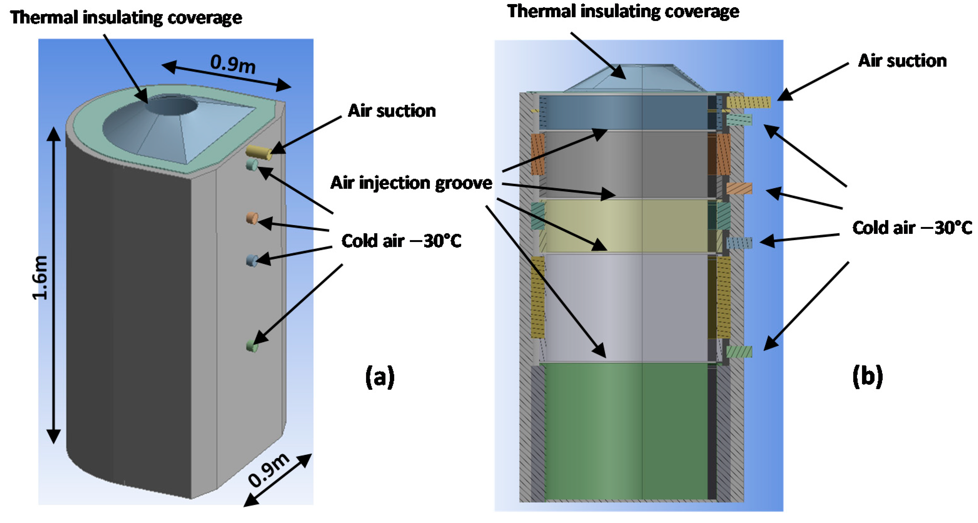
2.1. Geometry of the PBC Cabin
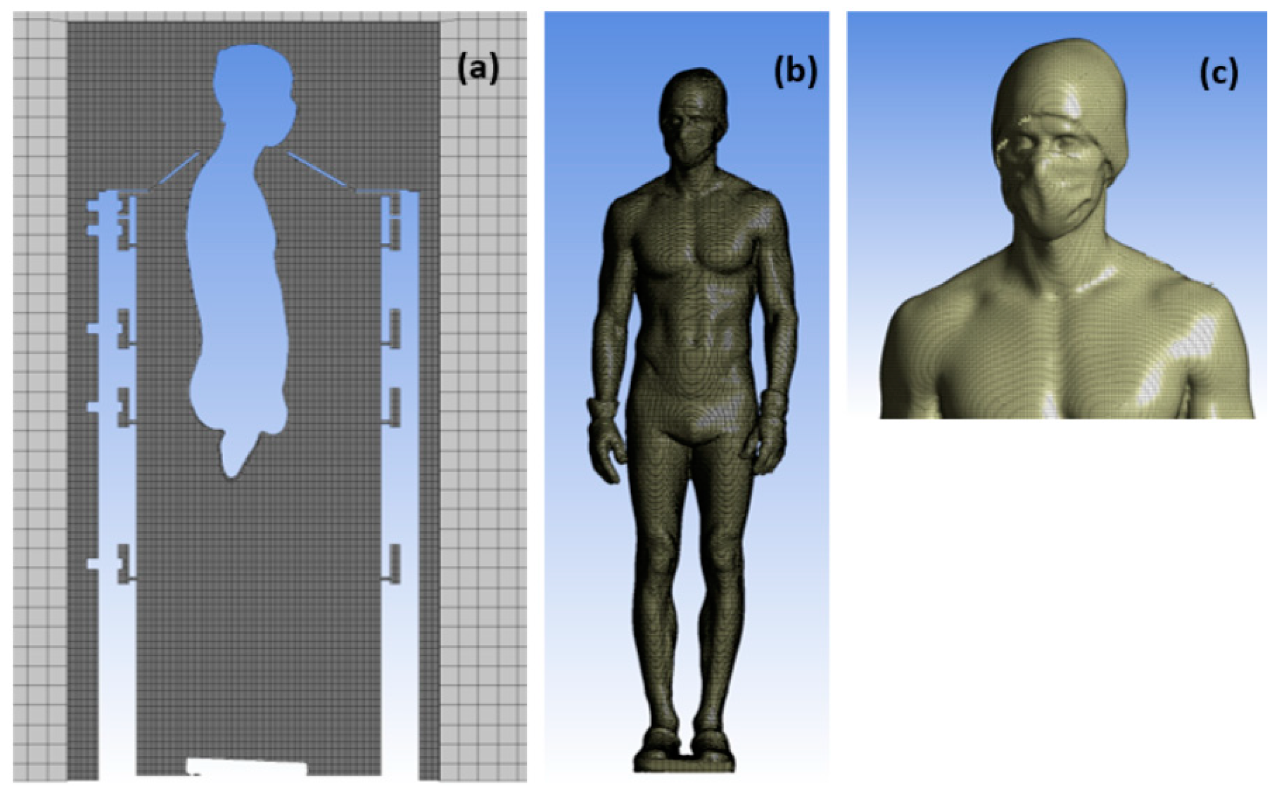
The first step of the numerical process is to define the geometry of the PBC cabin, which was created using the CAD software ANSYS Workbench© Design Modeler (ANSYS 2020 R2, ANSYS, Inc., Canonsburg, PA, USA). The main dimensional characteristics are equivalent to those of most nitrogen-based PBC cabins (Figure 2). The main innovation of the PBC cabin presented herein lies in its cooling system, which does not involve nitrogen. Contrary to conventional, nitrogen-based PBC cabins designed to release the cryogenic fluid through a single injection nozzle, the new system injects cold air through 12 nozzles distributed over 4 levels (h = 50 cm, 90 cm, 110 cm and 140 cm). Such design is able to provide personalized cryotherapy protocols by targeting specific body regions (Figure 2 and Figure 3). For instance, air flow may be distributed over all nozzles, or targeted at a given body area by injecting cold air on a single level (for example, the hips). For each level (Figure 2 and Figure 3), cold air is injected through three nozzles located at 90° apart (one on the patient’s back and the other two on each side).
The cold air jet impacts the inner wall before falling down into a channel that is gradually filled with cold air, which in turn is discharged through an open groove inside the cabin (Figure 2). As a result, cold air does not directly impact the patient, which significantly reduces the risk of burns. The groove design should homogenize the temperature within the treatment area, while optimizing heat transfer and air mixing.
A suction nozzle is located at the top of the cabin to restrict cold air evacuation at the patient’s neck level, which also averts cooling of the surrounding area. In complement, a thermal insulating cover is placed at the top of the cabin to further prevent heat loss [26].
Once the geometry of the PBC cabin has been defined, the 3D geometry of a human body standing in the center of the cabin is added, which was acquired by 3D scanning of a male subject (height: 1.9 m) wearing cryotherapy-specific protective clothing (cap, gloves, clogs). Segmentation of the geometry resulted in zones where differentiated thermal boundary conditions can be applied (Figure 3).
The final step related to the geometry consists in defining a computational domain of dimensions equivalent to those of the room in which the PBC cabin is located (Figure 4). The computational domain includes two openings in the lower part (pressure outlets), and the walls are considered adiabatic (no heat transfer).

2.2. Mesh

Meshing of the computational domain was carried out using the ANSYS Workbench Meshing® software, allowing creation of surface and/or volume meshes, structured or not. A surface mesh is first created on the body surface, and a volume mesh for the fluid domain. As shown in Figure 4, two volumes have been created. The smaller volume surrounding the cabin involves a refined mesh made of 0.01 m cells, and the Cartesian structured mesh improves the convergence of the results while limiting the number of cells in the global grid. As seen in Figure 5, two different meshes were required by the simulation. In the largest volume, the structured mesh is composed of 0.1 m cells. The complete mesh contains more than 17 million cells.

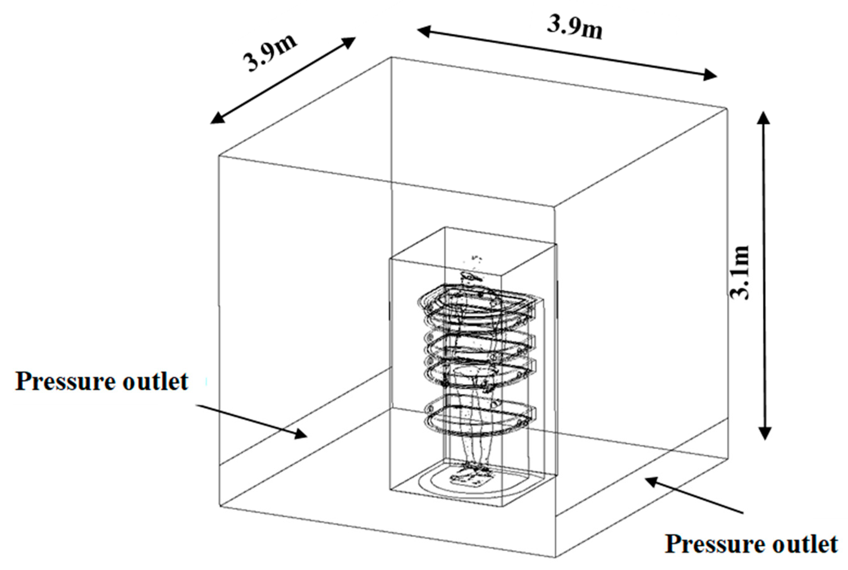
2.3. Boundary Conditions

In this study, cold air is injected at a temperature of −30 °C at a flow rate of 40 m3/h (based on a 30 kW cooling unit). Since the injection is distributed over 12 nozzles, a mass flow rate of 0.00134 kg/s per nozzle (based on a density of 1.4517 kg/m3) is derived. The suction flow rate is fixed at 0.016 kg/s which, as mentioned earlier, reduces the fluid losses at the patient’s neck level and ensures mass conservation. A pressure outlet boundary condition is applied at the lower part of the computational domain. The walls of the cabin as well as those of the room are considered adiabatic (no heat transfer). Computation is initialized at a temperature of 20 °C.
In the first simulation, the human body is assumed to be adiabatic (zero surface flux), but in the following study, a surface temperature is applied on the different segments of the human body. Temperatures were measured by infrared thermography on the body of a patient prior to a WBC session [1].
For simplification purposes, the body surface temperature remains constant throughout the calculation. A specific material database is created to better account for variations in the thermo-physical properties of air with temperature. The boundary conditions are summarized in Table 1.

2.4. Numerical Setup

In this study, we used the commercial computational code ANSYS Fluent® 2020 R2, a CFD code based on the finite volume method for solving the system of equations that govern the fluid flow. In our study, the problem is three-dimensional, time-dependent and non-isothermal. Due to the temperature difference between the human body (between 8 and 32 °C) and the surrounding fluid (air stagnating at −30 °C), the air flow near the body is considered as a natural convection flow. The thermal boundary layer as well as the airflow around the human body are considered to be fully turbulent. Therefore, we used the k-ε turbulence model, which is perfectly suited to detect recirculation phenomena. The SIMPLE algorithm was preferred to solve the pressure-velocity coupling, using a first-order discretization scheme.
Heat transfer as well as convective mass transfer are described by the following equations:
The continuity equation:
w x x + w y y + w z z = 0
The Navier-Stokes equations:
w x τ + w x w x x + w y w x y + w z w x z = 1 ρ P x + ν ( 2 w x x 2 + 2 w x y 2 + 2 w x z 2 ) + g x
w y τ + w x w y x + w y w y y + w z w y z = 1 ρ P y + ν ( 2 w y x 2 + 2 w y y 2 + 2 w y z 2 ) + g y
w z τ + w x w z x + w y w z y + w z w z z = 1 ρ P z + ν ( 2 w z x 2 + 2 w z y 2 + 2 w z z 2 ) + g z
The energy equation:
ρ f C p , f ( T f τ + w x T f x + w y T f y + w z T f z ) = x ( λ f T f x ) + y ( λ f T f y ) + z ( λ f T f z )
With w being the fluid velocity (m/s); ν the dynamic viscosity (kg/m·s); x ,   y ,   z the spatial coordinates (m); P the pressure (Pa); ρ the density (kg/m3); T the temperature (K); C p the specific heat (J/Kg·K); and λ the thermal conductivity (W/m/K).
An adaptive time step ensures faster convergence of the results. The unsteady computation is performed with a time step of 0.1 s on a workstation featuring 24 Xeon 2.6 GHz processors and 192 GB of RAM.

3. Results

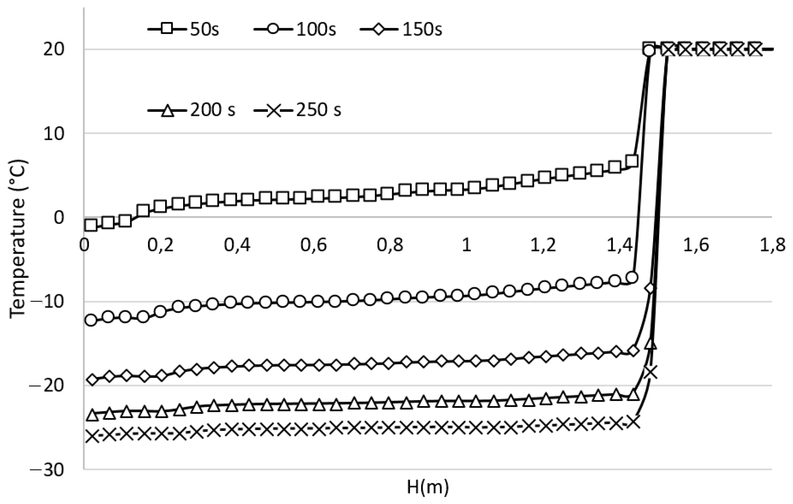
3.1. Time Evolution of the Temperature Inside the Cabin, Pre-Cooling Phase

The pre-cooling phase precedes the patient’s entry into the PBC cabin. Temperatures close to the set temperature (−30 °C in this study) are required, and should in any case be low enough to trigger the desired therapeutic effect. Figure 6 shows the time evolution of the temperature inside the PBC cabin plotted along a vertical axis. Results reveal a progressive decrease in temperature. The thermal stratification effect is limited and the temperatures seem to be quite homogeneous in the desired treatment area. Moreover, results suggest that a waiting period of 250 s (approximately 4 min) is required to reach a temperature close to −25 °C in the therapy area. The linear behavior and the slight slope of the curves (between 0.2 m and 1.4 m) confirm a weak thermal stratification.

3.2. Convective Heat Transfer between the Human Body and Its Environment

The CFD calculations carried out for the pre-cooling phase of the cabin have been carried out disregarding the heat transfer between the human body and its close environment, the body being considered as a simple adiabatic “obstacle”. However, the heat exchange between the human body and its surrounding environment is essential when quantifying the efficiency of the air cooling process in a PBC cabin. In the second part of the study, we included these heat transfers, with the objective of simulating a 3-min PBC session and investigating the influence of the body-generated heat source on the temperature field inside the PBC cabin. To overcome a lack of experimental data in partial body cryotherapy at −30 °C, we applied a differentiated temperature for each of the body segments listed in the boundary conditions of the study. These temperatures are derived from experimental measurements performed on a human before a cryotherapy session [1]. We assume that the skin temperature varies more slowly when the body is subjected to a temperature of −30 °C than when it is subjected to temperatures below −110 °C. Figure 7 presents the evolution of the temperature field displayed in planes x-y and y-z for the 3 min of the cryotherapy session.
Additionally, Figure 8 shows the time evolution of the temperature plotted along a vertical axis. Compared to the first calculation (end of cooling), it can be seen that the heat contribution stemming from the presence of the human body results in a significant increase in the temperatures inside the PBC cabin. In fact, once inside the cabin, the human body transfers heat to its environment by radiation, conduction and natural convection [27]. During exposure to cold, the thin air layer (called boundary layer) developing on the surface of the human body limits heat transfer from the body to the air inside the cabin [28]. The development of this boundary layer can be observed in Figure 7, in the form of a thermal plume. It should also be noticed that the thermal plume accentuates the thermal stratification phenomenon. A common observation in PBC is that the upper part of the body is influenced by the outside environment at room temperature, while the lower limbs of the body are immersed in a much colder atmosphere. As a result, cold air (of high density) stagnates at the bottom of the cabin, while warmer air (of lower density) tends to rise to the top of the cabin. Consequently, this vertical temperature gradient will lead to a heterogeneity in skin temperature, with a more pronounced cooling of the lower limbs [1].

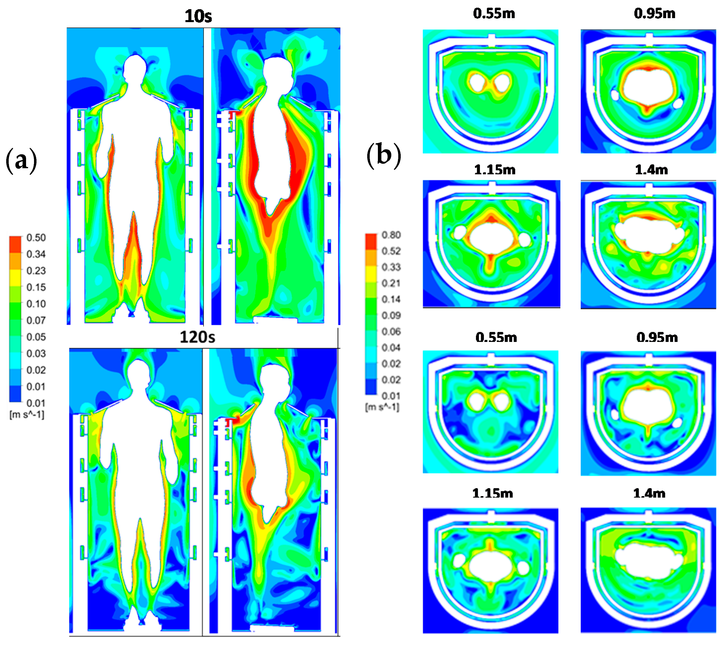
3.3. Time Evolution of the Air Velocity Inside the Cabin during a Cryotherapy Session

The velocity fields depicted in Figure 9 are plotted in two perpendicular vertical planes (a) and four horizontal planes (b) (h = 0.55 m, h = 0.95 m, 1.15 m and h = 1.4 m) at two moments of the cryotherapy session (10 and 120 s). It is worthwhile noting that the range of velocities has been limited in order to better highlight the velocity differences. Compared to the first calculation which discarded the heat input from the human body, we can see that the thermal plume developing around the body accelerates the airflow in the boundary layer as well as the heat transfers within the cabin. After 10 s, the maximum velocity in the thermal plume is found to be greater than 0.5 m/s, while the maximum fluctuating velocity is about 0.1 m/s.
Interestingly, compared to a human body at room temperature [29], the velocities within the thermal plume are more than doubled (about 0.25 m/s after 10 s at room temperature versus 0.5 m/s at −30 °C). These results suggest that the flow velocity in the boundary layer depends on the temperature gradient between the body and its environment.

3.4. Time Evolution of the Heat Flux on the Body Surface

Monitoring of the surface heat flux was performed throughout the iterative calculation process. Although the body surface temperature does not vary during the calculation, the results provide an estimation of the evolution of the surface flux, a reliable indicator of the skin cooling intensity. Figure 10 depicts the time evolution of the surface heat flux for each body zone detailed in Figure 3.
It can be noted that the value of the heat flux decreases during the cryotherapy session, which is in accordance with the observations made from experimental measurements performed in whole body cryotherapy [1]. Thermal flux decreases particularly in certain areas of the body that are more exposed to cold, such as the back of the arms, back, trunk and torso. The heat flux on the face follows a quasi-linear trend, as this area is not subject to negative temperatures. These curves follow a decreasing exponential trend in the first 120 s, followed by a quasi-linear trend thereafter. Although our model does not consider the physiological response of the human body, our results seem to be consistent with experimental measurements [16]. The highest heat flow is found at the legs, which are in contact with the lowest temperatures (see Figure 10). The colder the air near the body, the greater the heat exchange and loss, resulting in a decrease in surface temperature. Finally, Figure 11 depicts the distribution of heat flux on the body surface throughout a PBC session at −30 °C. This figure reveals the areas that are more likely to cool down, such as the legs. During the first 10 s of the session, the temperatures within the cabin are still relatively homogeneous and the heat flux takes place above the entire body part subjected to negative temperatures. During the PBC session, the heat supply generated by the human body affects the airflow and thermal conditions within the cabin. The overall temperature within the cabin increases, resulting in a decrease in the value of the heat flux at the body surface, which is particularly noticeable in the upper part of the body (Figure 11). It appears that the cooling is more marked in the lower part of the body, where the thermal plume develops. The results also suggest a close relationship between the velocity within the boundary layer and the cooling intensity.
On the one hand, the resulting flow pushes warm air away from the body, but on the other hand, it accelerates the heat transfer between the air at room temperature and the air inside the cabin. The result is a gradual increase in temperature within the therapy area.

4. Limitations

The results of this study must be interpreted in view of several limitations. First, the numerical model does not take the physiological behavior of the human body into account. In fact, the interaction between the human body and the cryocabin initiates mostly at the skin level, and the skin temperature may reflect the balance between heat loss to the environment and heat generated by metabolically active tissues. Furthermore, the results presented in this study are based on a calculation performed with a flow rate distributed uniformly over all 12 injection nozzles. Further calculations will be necessary to determine the influence of the flow distribution on the thermal and aeraulic behavior of the cabin. Finally, the calculations were performed under the assumption that the skin temperature did not vary during the calculation. This simplification is likely to bias the results and further measurements will be necessary to obtain the experimental data that will have to be implemented in the computational code.

5. Conclusions

This study aimed at laying the foundations of an in-depth reflection for the development of a new generation of PBC cabins using a cryogenic fluid that would not be nitrogen. In this perspective, we designed a cryotherapy cabin implementing an electric compressor air cooling technology intended to produce cold air at −30 °C. Unlike conventional nitrogen-based PBC cabins designed to release cryogenic fluid through a single injection nozzle, the new system can inject cold air through 12 nozzles distributed over 4 levels. The main advantage of such a design would be to provide personalized cryotherapy protocols by targeting specific areas of the body. For example, the air flow could be distributed on all the nozzles, or targeted on a given body area by injecting cold air on a single level (for example, the hips). Once the geometry of the cryotherapy cabin was defined, we proceeded to its validation by means of a numerical modeling. The objective was to optimize the circulation of the cold air flows in the cabin. The numerical study was carried out in two successive phases, the first one being to model the pre-cooling phase and to estimate the time needed to reach an average temperature close to the reference temperature of −30 °C. We estimated that a waiting time of approximately 4 min was required to reach a temperature close to −25 °C in the therapy area. The second phase was intended to model a 3-min cryotherapy session by considering the thermal transfers between the human body and its environment. The results demonstrated that the heat input from the human body significantly increases the temperatures within the PBC cabin, as the thermal plume accelerates the airflow in the boundary layer, thereby promoting heat transfer within the cabin. In addition, a monitoring of the body surface heat flux was performed throughout the calculation and provided an estimate of the skin cooling rate. Findings indicate that heat flux decreased more significantly in specific areas of the body that are more exposed to cold, such as the back arms, back, trunk and torso. This study was a first step in the development of a new generation of partial body cryotherapy cabin which is designed to be economical and free of safety concerns. An experimental study will be necessary first to validate the concept and second to adapt the duration of the cryotherapy protocol, the ultimate goal being to obtain both optimal levels of analgesia and reduction of tissue temperature.

Author Contributions

Conceptualization, G.P. and B.B.; methodology, F.B. (Fabien Beaumont); software, F.B. (Fabien Beaumont); validation, H.H., G.P. and B.B.; formal analysis, F.B. (Fabien Bogard); investigation, F.B. (Fabien Beaumont); resources, S.M.; data curation, H.H.; writing—original draft preparation, F.B. (Fabien Beaumont); writing—review and editing, S.M.; visualization, F.B. (Fabien Bogard); supervision, G.P.; project administration, B.B.; funding acquisition, F.B. (Fabien Bogard). All authors have read and agreed to the published version of the manuscript.

Funding

This research received no external funding.

Institutional Review Board Statement

Not applicable.

Informed Consent Statement

Not applicable.

Data Availability Statement

Not applicable.

Conflicts of Interest

The authors declare no conflict of interest.

References

  1. Polidori, G.; Taiar, R.; Legrand, F.; Beaumont, F.; Murer, S.; Bogard, F.; Boyer, F.C. Infrared thermography for assessing skin temperature differences between Partial Body Cryotherapy and Whole Body Cryotherapy devices at −140 °C. Infrared Phys. Technol. 2018, 93, 158–161. [Google Scholar] [CrossRef]
  2. Hausswirth, C.; Schaal, K.; Le Meur, Y.; Bieuzen, F.; Filliard, J.-R.; Volondat, M.; Louis, J. Parasympathetic activity and blood catecholamine responses following a single partial-body cryostimulation and a whole-body cryostimulation. PLoS ONE 2013, 8, e72658. [Google Scholar] [CrossRef] [Green Version]
  3. Banfi, G.; Melegati, G.; Barassi, A.; Dogliotti, G.; Melzi d’Eril, G.; Dugué, B.; Corsi, M.M. Effects of whole-body cryotherapy on serum mediators of inflammation and serum muscle enzymes in athletes. J. Therm. Biol. 2009, 34, 55–59. [Google Scholar] [CrossRef]
  4. Straburzyńska-Lupa, A.; Kasprzak, M.P.; Romanowski, M.W.; Kwaśniewska, A.; Romanowski, W.; Iskra, M.; Rutkowski, R. The Effect of Whole-Body Cryotherapy at Different Temperatures on Proinflammatory Cytokines, Oxidative Stress Parameters, and Disease Activity in Patients with Ankylosing Spondylitis. Oxid. Med. Cell. Longev. 2018, 2018, 2157496. [Google Scholar] [CrossRef] [PubMed] [Green Version]
  5. Algafly, A.A.; George, K.P. The effect of cryotherapy on nerve conduction velocity, pain threshold and pain tolerance. Br. J. Sports Med. 2007, 41, 365–369. [Google Scholar] [CrossRef] [PubMed]
  6. Rymaszewska, J.; Ramsey, D.; Chładzińska-Kiejna, S. Whole-body cryotherapy as adjunct treatment of depressive and anxiety disorders. Arch. Immunol. Ther. Exp. 2008, 56, 63–68. [Google Scholar] [CrossRef] [Green Version]
  7. Vitenet, M.; Tubez, F.; Marreiro, A.; Polidori, G.; Taiar, R.; Legrand, F.; Boyer, F.C. Effect of whole body cryotherapy interventions on health-related quality of life in fibromyalgia patients: A randomized controlled trial. Complement. Ther. Med. 2018, 36, 6–8. [Google Scholar] [CrossRef] [PubMed]
  8. Bouzigon, R.; Grappe, F.; Ravier, G.; Dugue, B. Whole- and partial-body cryostimulation/cryotherapy: Current technologies and practical applications. J. Therm. Biol. 2016, 61, 67–81. [Google Scholar] [CrossRef] [PubMed]
  9. Huizenga, C.; Zhang, H.; Arens, E.; Wang, D. Skin and core temperature response to partial-and whole-body heating and cooling. J. Therm. Biol. 2004, 29, 549–558. [Google Scholar] [CrossRef] [Green Version]
  10. Stocks, J.M.; Taylor, N.A.S.; Tipton, M.J.; Greenleaf, J.E. Human physiological responses to cold exposure. Aviat. Space Environ. Med. 2004, 75, 444–457. [Google Scholar]
  11. Castellani, J.W.; Young, A.J. Human physiological responses to cold exposure: Acute responses and acclimatization to prolonged exposure. Auton. Neurosci. Thermoregul. 2016, 196, 63–74. [Google Scholar] [CrossRef] [Green Version]
  12. Cholewka, A.; Stanek, A.; Sieroń, A.; Drzazga, Z. Thermography study of skin response due to whole-body cryotherapy. Skin Res. Technol. 2012, 18, 180–187. [Google Scholar] [CrossRef]
  13. Fonda, B.; De Nardi, M.; Sarabon, N. Effects of whole-body cryotherapy duration on thermal and cardio-vascular response. J. Therm. Biol. 2014, 42, 52–55. [Google Scholar] [CrossRef]
  14. Costello, J.T.; McInerney, C.D.; Bleakley, C.M.; Selfe, J.; Donnelly, A.E. The use of thermal imaging in assessing skin temperature following cryotherapy: A review. J. Therm. Biol. 2012, 37, 103–110. [Google Scholar] [CrossRef] [Green Version]
  15. Bleakley, C.; Hopkins, J. Is it possible to achieve optimal levels of tissue cooling in cryotherapy? Phys. Ther. Rev. 2010, 15, 344–350. [Google Scholar] [CrossRef]
  16. Polidori, G.; Elfahem, R.; Abbes, B.; Bogard, F.; Legrand, F.; Bouchet, B.; Beaumont, F. Preliminary study on the effect of sex on skin cooling response during whole body cryostimulation (−110 °C): Modeling and prediction of exposure durations. Cryobiology 2020, 97, 12–19. [Google Scholar] [CrossRef]
  17. Osczevski, R.; Bluestein, M. The new wind chill equivalent temperature chart. Bull. Am. Meteorol. Soc. 2005, 86, 1453–1458. [Google Scholar] [CrossRef] [Green Version]
  18. Bouzigon, R.; Arfaoui, A.; Grappe, F.; Ravier, G.; Jarlot, B.; Dugue, B. Validation of a new whole-body cryotherapy chamber based on forced convection. J. Therm. Biol. 2017, 65, 138–144. [Google Scholar] [CrossRef]
  19. Chorowski, M.; Piotrowska, A.; Sieron, A.; Stanek, A. Safety Aspects of Cryochamber Operation. In AIP Conference Proceedings; American Institute of Physics: College Park, MD, USA, 2013; Volume 1573. [Google Scholar] [CrossRef]
  20. Agnieszka, P. Safety aspects of whole-body cryochamber and cryosauna operation. IOP Conf. Ser. Mater. Sci. Eng. 2017, 278, 012125. [Google Scholar] [CrossRef]
  21. Dugue, B.; Bernard, J.; Bouzigon, R.; Nardi, M.; Wafa, D.; Junior, J.; Guilpart, J.; Lombardi, G.; Miller, E.; Tiemessen, I. Note D’information-Institut International du Froid-Cryothérapie ou Cryostimulation à Corps Entier; International Institute of Refrigeration: Paris, France, 2020. [Google Scholar]
  22. Bernard, J.P.; Dallais, A. Safe and Efficient Use of Liquid Nitrogen in Cryotherapy Applications. In Proceedings of the 3rd IIR Conference on Cold Applications in Life Sciences-Cryotherapy and Cryopreservation, Saint Petersbourg, Russia, 12–14 September 2018. [Google Scholar]
  23. Greenwald, E.; Christman, M.; Penn, L.; Brinster, N.; Liebman, T.N. Cold panniculitis: Adverse cutaneous effect of whole-body cryotherapy. JAAD Case Rep. 2018, 4, 344–345. [Google Scholar] [CrossRef] [Green Version]
  24. Gużda, A.; Szmolke, N. Compressors in Heat Pumps. Mach. Dyn. Res. 2015, 39, 71–83. [Google Scholar]
  25. Baranov, A.; Pakhomov, O.; Fedorov, A.; Ivanov, V.; Zaitsev, A.; Polyakov, R. Technique and Technology of Whole-Body Cryotherapy (WBC). Low-Temp. Technol. 2019, 30, 1–25. [Google Scholar] [CrossRef] [Green Version]
  26. De Nardi, M.; Silvani, S.; Facheris, C.; Pagnoncelli, M.; Bisio, A.; Faelli, E.; La Torre, A.; Ruggeri, P.; Codella, R. Effectiveness and safety of a thermal insulating coverage on the top of the cryo-cabin during a partial-body cryostimulation. J. Therm. Biol. 2021, 97, 102901. [Google Scholar] [CrossRef]
  27. Savic, M.; Fonda, B.; Sarabon, N. Actual temperature during and thermal response after whole-body cryotherapy in cryo-cabin. J. Therm. Biol. 2013, 38, 186–191. [Google Scholar] [CrossRef]
  28. Schlichting, H.; Gersten, K. Boundary-Layer Theory; Springer: Berlin/Heidelberg, Germany, 2016. [Google Scholar]
  29. Liu, Y.; Liu, Z.; Luo, J. Numerical Investigation of the Unsteady Thermal Plume around Human Body in Closed Space. Procedia Eng. 2015, 131, 1919–1926. [Google Scholar] [CrossRef] [Green Version]
Figure 1. Typical refrigeration with single-stage vapor compression.
Dynamics 01 00013 g001
Figure 2. External view of the PBC cabin (a); vertical cross-section of the cabin showing the injection and suction system integrated in the inner wall of the cabin (b).
Dynamics 01 00013 g002
Figure 3. Cross-sectional view showing the different levels of air injection and allowing differentiated protocols according to the body zones (a); body zones used for thermal boundary conditions (b).
Dynamics 01 00013 g003
Figure 4. Computational domain showing the PBC cabin in a room.
Dynamics 01 00013 g004
Figure 5. Cross-section of the mesh of the computational domain (a); body surface mesh (b); detail of the surface mesh on the upper body (c).
Dynamics 01 00013 g005
Figure 6. Time evolution of the temperature during the pre-cooling phase of the cabin, plotted along a vertical axis.
Dynamics 01 00013 g006
Figure 7. Time evolution of the temperature displayed in two vertical planes passing through the center of the cabin, for the first 180 s of the cryotherapy session.
Dynamics 01 00013 g007
Figure 8. Time evolution of the temperature during the cryotherapy session and plotted along a vertical axis, comparison with the temperature obtained at the end of the cooling process.
Dynamics 01 00013 g008
Figure 9. (a) Velocity maps in two mutually perpendicular planes x-y and y-z at t = 10 s and 120 s. (b) Velocity maps in three different horizontal planes y = 0.55 m; y = 0.95 m; y = 1.15 m and y = 1.4 m at t = 10 s and 120 s.
Dynamics 01 00013 g009
Figure 10. Time evolution of the surface heat flux (W/m2) for each body segment.
Dynamics 01 00013 g010
Figure 11. Time evolution of the heat flux distribution at the body surface.
Dynamics 01 00013 g011
Table 1. CFD boundary conditions.
Mass Flow RateTemperature
Air injection nozzles0.0013 kg/s−30 °C
Suction nozzle0.016 kg/s
Pression
Pressure outlet room1 ATM20 °C
Surface heat flux
Cabin walls + room φ = 0 W/m²
Caps + gloves + clogs φ = 0 W/m²
Température
Back legs 31.16 °C
Arms on the back side 31.98 °C
Trunk + torso 31.53 °C
Back 29.74 °C
Arms on the front side 31.66 °C
Legs on the front side 30.55 °C
Face 31.53 °C
Publisher’s Note: MDPI stays neutral with regard to jurisdictional claims in published maps and institutional affiliations.

