Article

Strain Engineering of ZrO2@TiO2 Core@shell Nanoparticle Photocatalysts

Engineering and Physical Sciences, Aston University, Birmingham B4 7ET, UK
Solar 2023, 3(1), 15-24; https://doi.org/10.3390/solar3010002
Submission received: 10 October 2022 / Revised: 29 December 2022 / Accepted: 31 December 2022 / Published: 4 January 2023
(This article belongs to the Special Issue Nanotechnology in Photo-Triggered Processes)

Abstract

:
TiO2 photocatalysts can provide carbon-capture utilization and storage by converting atmospheric CO2 to green hydrogen, but the efficiency of the current photocatalysts is still too low for economical usage. Anatase TiO2 is effective in transferring the electrons and holes produced by the photoelectric effect to reactants because of its oxygen-terminated surfaces. However, the anatase TiO2 bandgap is 3.2 eV, which requires photons with wavelengths of 375 nm or less to produce electron–hole pairs. Therefore, TiO2 is limited to using a small part of the solar spectrum. Strain engineering has been used to design ZrO2@TiO2 core@shell structures with large strains in the TiO2 shell, which reduces its bandgap but maintains octahedral facets for charge separation and oxygen-terminated surfaces for the catalysis of reactants. Finite element analysis shows that shell thicknesses of 4–12 nm are effective at obtaining large strains in a large portion of the shell, with the largest strains occurring next to the ZrO2 surface. The c-axis strains for 4–12 nm shells are up to 7%. The strains reduce the bandgap in anatase TiO2 up to 0.35 eV, which allows for the use of sunlight with wavelengths up to 421 nm. For the AM 1.5 standard spectrum, electron–hole pair creation in 4 nm thick and 10 nm thick TiO2 shells can be increased by a predicted 25% and 23%, respectively. The 10 nm thick shells provide a much larger volume of TiO2 and use proportionally less ZrO2. In addition, surface-plasmon resonators could be added to further extend the usable spectrum and increase the production of electron–hole pairs many-fold.

1. Introduction

Renewable energy sources are increasingly being used for electricity generation, and electric passenger vehicles are increasing their market share. However, other sectors, such as agriculture and home heating, are more difficult to decarbonize, and worldwide CO2 emissions continue to rise. To meet net zero goals, other methods of decarbonization are needed. Two promising solutions are carbon capture, utilization, and storage; and green hydrogen, hydrogen produced with zero greenhouse gas emissions.
TiO2 photocatalysts have many properties that are useful for carbon-capture utilization and storage by converting atmospheric CO2 into useful chemicals such as formic acid or formaldehyde, which can be further converted to green hydrogen [1,2,3,4,5,6]. Anatase TiO2 is effective at transferring the electrons and holes produced by the photoelectric effect to reactants because of its oxygen-terminated surfaces. In addition, facetted TiO2 nanoparticles separate photoelectrons and holes to different facet surfaces [7], which prevents them from recombining for long enough to transfer the charges to the reactants. The oxygen-terminated surfaces are good for attracting and holding CO, CO2, H2O, and positively charged ions. The (001) facets of the decagon are terminated with both oxygen and titanium atoms, which are good for attracting negatively charged ions. Metal nanoparticles can be added as surface-plasmon resonators on the (101) facets in the same manner as for homogenous nanoparticles [8,9,10]. The large multiplying effect of both facets and surface-plasmon resonators indicates that a scarcity of excitons is limiting the photocatalytic reactions. The conversion of CO2 to formaldehyde or formic acid is endothermic, so energy must be supplied by electron–hole pairs in an excited state to drive the CO2 reduction reactions. The use of TiO2 for hydrogen production extends back over 40 years [1]. However, the bandgap of anatase TiO2 is 3.2 eV, which requires photons with wavelengths of 375 nm or less to produce electron–hole pairs. Therefore, bulk TiO2 is limited to using a small part of the solar spectrum with wavelengths less than 375 nm. The energy required to convert CO2 to formic acid and to generate green hydrogen is less than 1 eV, so photons with wavelengths of up to 1200 nm could be used, which covers the entire UV-Vis spectrum.
TiO2 shells have previously been used with noble metal nanoparticle cores [3,4,5], which have incoherent interfaces and therefore low strain in the shell. Strain engineering has often been used with TiO2 films [6], which has been shown to lead to enhanced electron–hole production and photocatalytic activity [11,12]. However, strain engineering of TiO2 shell nanoparticles has not yet been reported. A suitable core material would need to have the same crystal structure and provide a large lattice mismatch with TiO2. A metal oxide core would provide the added benefit of strong covalent bonding with the TiO2 shell. Tetragonal-ZrO2, which has a 5% lattice mismatch with TiO2 [13,14,15], is selected as the core material for this study.
Photocatalyst research was advanced greatly by the discovery of charge separation on nanostructured facets [7] and the multiplying effect on photogeneration of electrons and holes using localized surface plasmon resonance (LSPR) [8,9]. These effects have recently been combined using PtRu alloy nanoparticle resonators to achieve a 29-fold increase in reduction compared to a standard commercial TiO2 catalyst [10]. Facets occur for nanoparticles with diameters < 2 μm because surface energy becomes more significant relative to binding energy when the size of the nanoparticle is small and a larger percentage of atoms are present on the surface [7].

2. Materials and Methods

Core@shell nanoparticles composed of tetragonal ZrO2 nanoparticle cores with an anatase TiO2 shell result in large strains in the TiO2 shell, which reduces its bandgap but maintains octahedral facets for charge separation and oxygen-terminated surfaces for catalysis of reactants. ZrO2 was chosen as the core material because of the 5% lattice mismatch and coherent tetragonal structure with anatase TiO2 [13,14,15]. Finite element analysis was conducted on ZrO2@TiO2 core@shell decahedral structures with octahedral facets to determine the strains in the crystallographic directions. The octahedral facets are normal to [101] directions in the tetragonal ZrO2 cores, as shown in Figure 1, and the crystallographic c-axis is aligned normal to the two (001) surfaces. The TiO2 shells are aligned in the same crystallographic directions to match the cores. The larger the core size relative to the shell thickness, the higher the average strains in the shell but the lower the volume fraction of TiO2. The tetragonal ZrO2 nanoparticle can be synthesized with diameters or 9–12 nm [16]. Therefore, to investigate a range of sizes, ZrO2 cores of 10 and 12 nm were used with TiO2 shell thicknesses of 4–12 nm in the FEA models. Anisotropic material constants were used for ZrO2 and TiO2, as listed in Table 1.
From the strains in the TiO2 shell, the shift in the bandgap was predicted using deformation potential theory [15]. First the c-axis strains were determined using FEA, and the TO2 shell was divided into four strain regions: 0.5–1.25%, 1.25–3%, 3–5%, and >5%. Strains less than 0.5% were neglected to avoid skewing the bandgap calculations toward the low strain regions, which have a less significant effect on the overall performance enhancement. The volume of each of the four strain regions in the shell was also determined from the FEA results. The volume fraction (fi) for each of the strain regions was determined by dividing the volume of each strain region (Vi) by the volume of the entire shell (Vs): fi = Vi/Vs. Then, the average bandgap shift in each strain region (ΔEgi) was determined from the average c-axis strain in each region using deformation potential theory [15].
The bandgap for ZrO2 is 5 eV, so electron–hole production from the core is assumed to be zero under standard solar illumination because wavelengths below 280 nm are completely absorbed by the atmosphere. The bandgap for anatase TiO2 without strain is 3.2 eV, so photons with a wavelength of 375 nm or less can produce electron–hole pairs by the photo-electric effect. Under strain, the bandgap shifts by ΔEgi, and a broader range of the solar spectrum, can be used to generate electron–hole pairs. The enhancement of the electron–hole pair production in each strain region was then determined from the photon energy (Pi) available from the increased usable solar spectrum up to the maximum wavelength determined from the reduced bandgap using Plank’s law. The standard AM 1.5 solar spectrum was used to determine the total increased energy available from the larger portion of the solar spectrum in each strain region determined from FEA. The increase in electron–hole pair production was then determined from the increased available photon energy in each strain region as
I i = P i P 0 P 0
The total increase in electron–hole pair production was then estimated by summing the increased electron–hole pair production in each strain region using the volume fractions determined above:
I = f i I i
The nanoparticle sizes and shapes were chosen to optimize the photocatalytic activity, and ZrO2 cores and TiO2 shells can both be synthesized in decahedral shapes with octahedral facets [16,17,18,19]. The controlled synthesis of tetragonal ZrO2 nanoparticles has been able to produce controlled nanoparticle sizes in the range of 8–12 nm [16]. The controlled synthesis of 12.6 nm thick anatase TiO2 shells has also been achieved [20]. Decahedrons can theoretically fit together with 100% space filling capacity, although the actual space filling would depend on the size variation. The final combined increase in photocatalytic activity for each core@shell nanoparticle was determined by multiplying the increase for the TiO2 shell by the volume percentage of the shell for each core size and the shell thickness studied.

3. Results

3.1. Strain in Core@shell Nanparticles

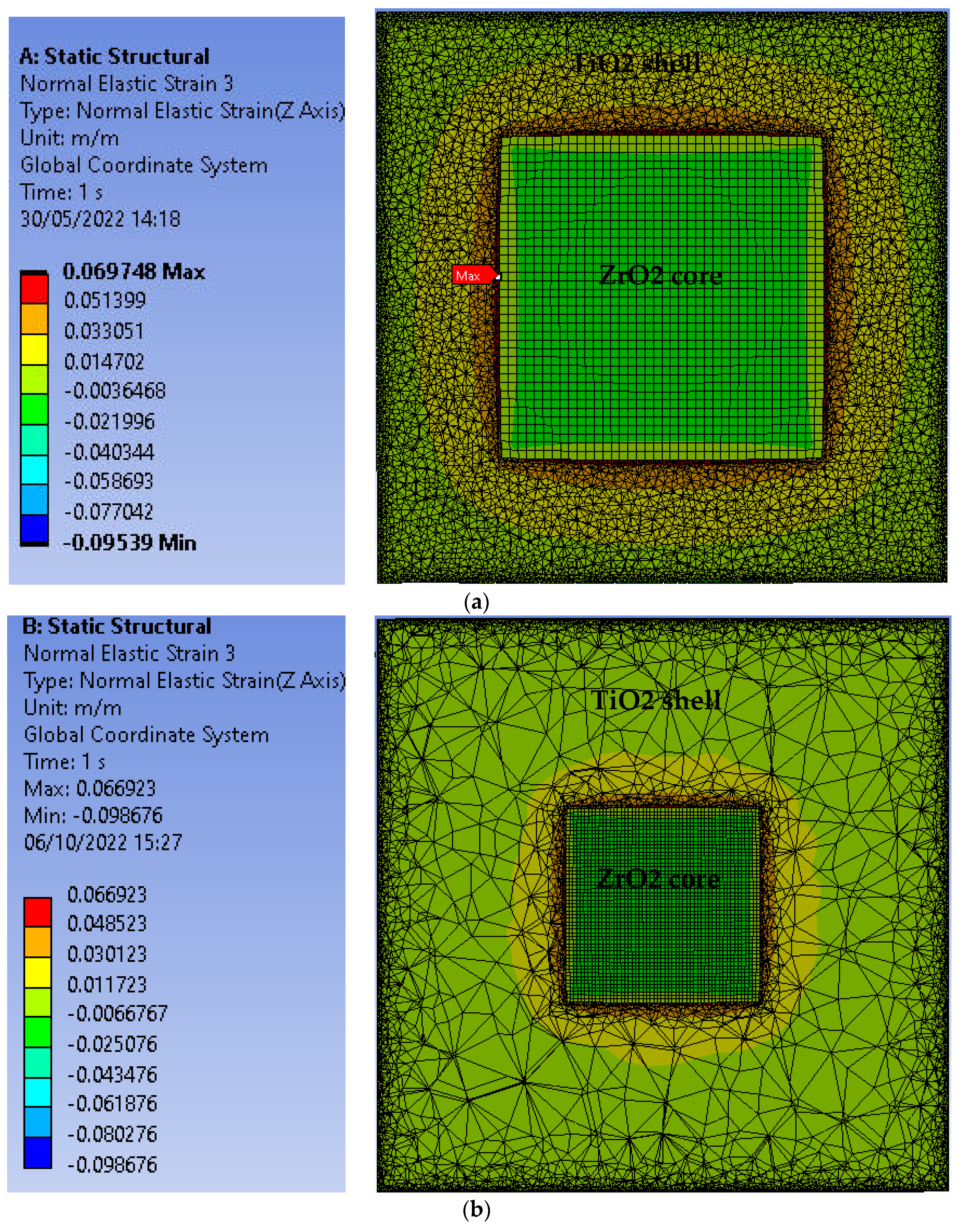
Finite element analysis was conducted to determine the strains in the TiO2 shells. A 5% lattice mismatch [13,14,15] was used to model the difference in lattice spacing between the tetragonal ZrO2 cores and TiO2 shells. The c-axis strains (z-axis strains in the FEA models) for core@shell nanoparticles with 10 nm cores and a shell thickness of 4 and 10 nm are shown in Figure 2. The ZrO2 core can be identified by its relatively uniform rectangular mesh in this cross-section, while the TiO2 shell has an irregular mesh with high mesh refinement near the interface and the surface. Automated mesh refinement was used to provide a more refined mesh near the locations with higher strain gradients. The c-axis strains change sharply at the core/shell interface with large tensile strains in the shell.
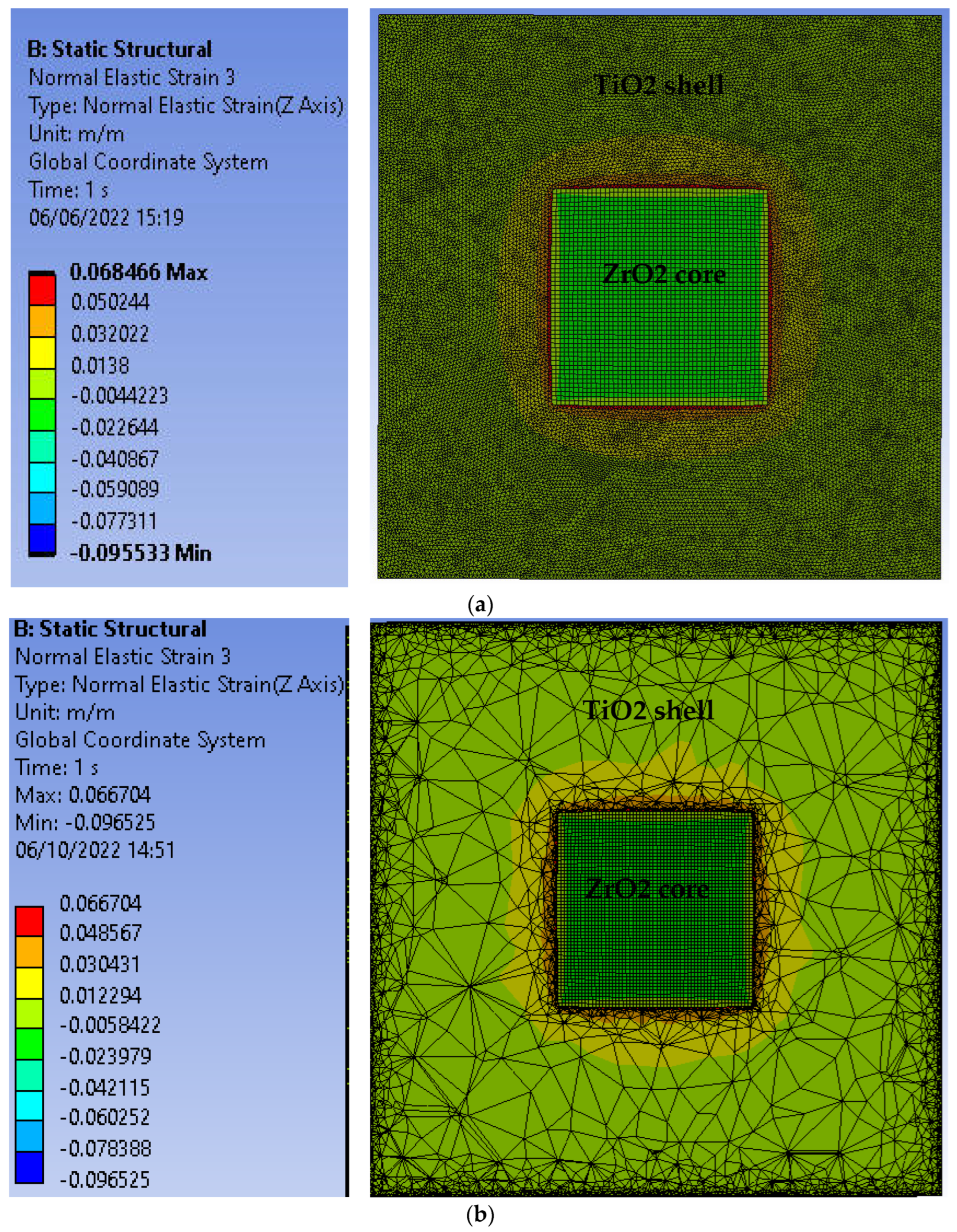
The c-axis strains for nanoparticles with 12 nm cores and 10–12 nm shells are shown in Figure 3. The c-axis strains are used for further analysis because the c-axis tensile strains lead to a decrease in the electronic bandgap [15]. The finite element models used 2.5–2.7 million nodes, and the strain results have converged within 2% for all cases. The maximum c-axis strains (up to 7%) in the TiO2 shell occur for the case with a 10 nm core and a 4 nm TO2 shell. The relatively thin shell results with slightly more of the mismatch strain in the shell than the other cases. However, since the core is under compressive stress in all three directions, the deformation of the core is relatively small for all cases. The shell, on the other hand, has a stress-free outer surface, which allows contraction normal to the surface to accommodate tensile strains parallel to the surface. Even for the relatively thick 12 nm shell and 10 nm core case, the maximum c-axis strains in the shell exceed 6.6%.
Note that the large strains described above are achieved for complete shells. If the shell is incomplete, the strains in the shell will be reduced. For the case of a 12 nm ZrO2 core and a 10 nm shell over only half the core, the maximum c-axis strain in the shell is only 3.7% compared to 6.8% for a complete shell.

3.2. Electron–Hole Pair Production

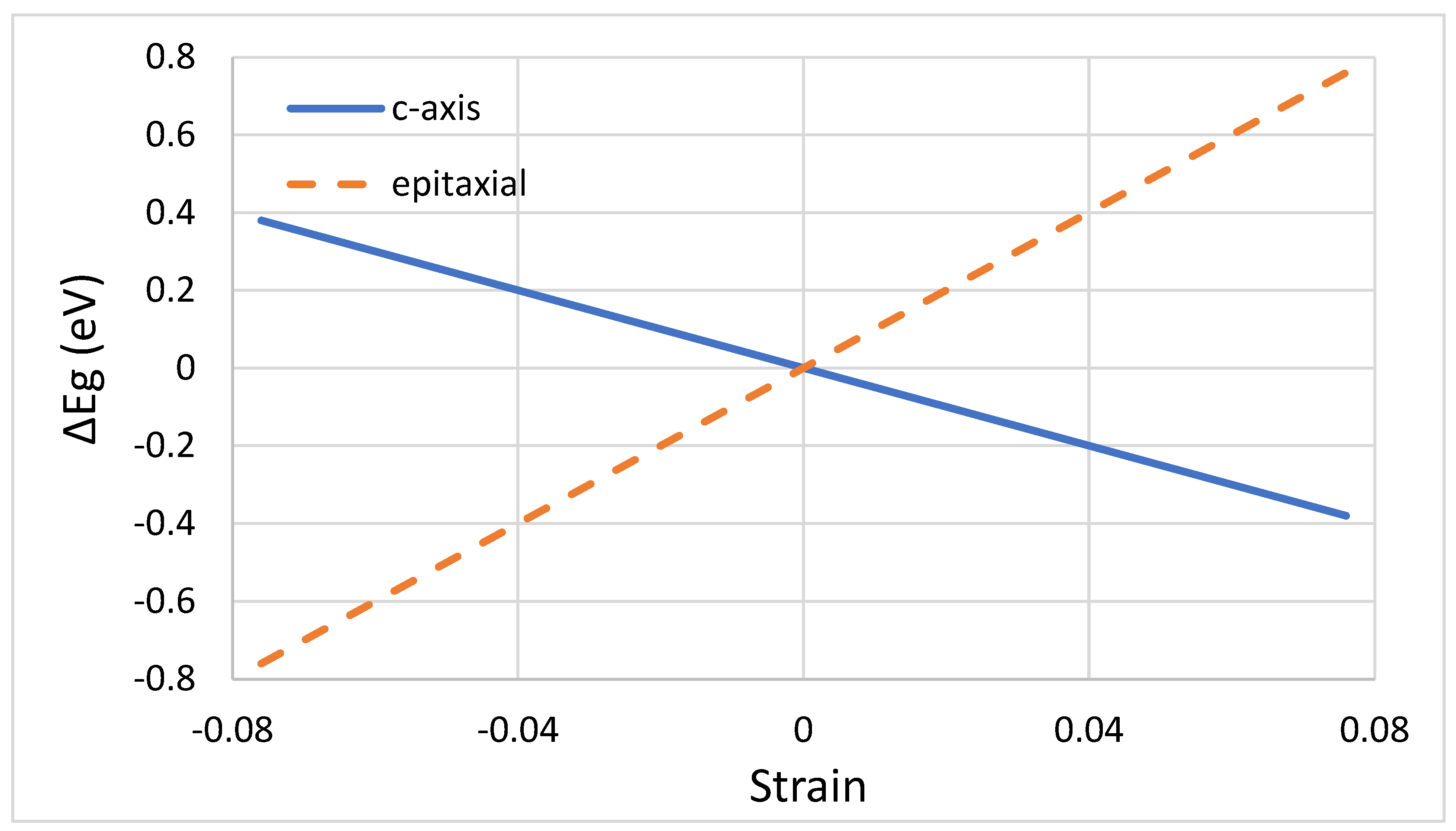
Figure 4 shows the relation between strains and bandgap in anatase TiO2. In the figure, epitaxial strain refers to biaxial strains in the plane normal to the c-axis, and the c-axis strains refer to the uniaxial strains in the c-axis [001] direction. The bandgap shifts in terms of strain were calculated from previous ab initio results for bandgap shift as a function of stresses [15]. Therefore, the c-axis strains, which were up to 7% as shown in Figure 2–3, are expected to reduce the bandgap in anatase TiO2 by up to 0.35 eV. The reduced bandgap allows for the use of sunlight with longer wavelengths up to a maximum of 421 nm. The average increase in electro-hole pair production for each case is found by determining the increase in each strain region based on the predicted bandgap shift, summing the regions and taking the average over the entire shell. The results for the seven cases studied are shown in Table 2. For the AM 1.5 standard spectrum, the electron–hole pair creation in 4 nm, 7 nm, and 10 nm thick TiO2 shells with 10 nm octahedral ZrO2 cores can be increased by a predicted 25%, 24%, and 22%, respectively, based on the results from FEA combined with the increased bandgap shown in Figure 4 and the corresponding increase in the solar spectrum usage. For 12 nm octahedral ZrO2 cores with 7 nm, 10 nm, and 12 nm shells, the predicted increases in electron–hole pair production in the shell are 25%, 23%, and 22%, respectively. However, since the highest strains are near the core/shell interface, the electron–hole pairs produced for shells 12 nm and thicker may not be as efficient in catalyzing reactions with CO2 or other molecules near the outer shell surface. A similar trend is seen with both core sizes. Higher strains in the thinner shell lead to higher electron–hole production in the shell, but thicker shells have a greater volume fraction of TiO2.
In core@shell nanoparticles, a complete continuous shell is not always achieved. To investigate the effect of an incomplete shell, a model was constructed consisting of a 12 nm decahedral ZrO2 core, half of which is covered by a TiO2 shell and half of which is left bare. For the case with an incomplete shell covering half the core, lower strains in the shell result, and the increase in electron–hole pair production in the shell is only 10% compared to 23% for the complete shell of the same thickness.

3.3. Core@shell Optmization

The thicker shells provide a larger volume of TiO2 and use proportionally less ZrO2. The 4 nm shell has the greatest increase in electron–hole pair production (25%) of the cases studied, but the shell is only 83% by volume. Therefore, the overall increase in photocatalytic activity for the nanoparticle is only 21% compared to a homogenous TiO2 nanoparticle. The results for other cases are shown in Table 2. Similar results are found for the same ratio of the shell thickness to the core diameter. Therefore, the optimal shell thickness is 70–83% of the core diameter, which results in a 22% increase in the predicted overall electron–hole production for the core@shell nanoparticle.

4. Discussion

Considering that the size variation would occur in practice, note that the other cases with complete shells are all expected to have an overall increase in electron–hole pair production under AM 1.5 solar illumination of 21–22%. Previous experiments with TiO2 thin films have shown a direct correlation between strain, electron–hole pair production, and photocatalytic activity [11,12]. These results indicate that ZrO2@TiO2 nanoparticles with 10–12 nm cores and 4–12 nm thick shells could provide an overall increase in photocatalytic activity of 20–22% provided a complete shell is formed. Various hydrothermal, solvothermal, and sol gel synthesis methods have been reported in the literature that could be applied to this nanoparticle system, e.g., [16,17,18,19,20]. ZrO2 nanoparticles of the optimal core size and structure have been reported [16]. The synthesis of the ZrO2 cores using that sol-gel method would be the first step. Then, the 9–12 nm t-ZrO2 nanoparticles would be used, coated with TiO2 shells. Ye et al. [20] grew TiO2 shells by using tetrabutyl titanate as the precursor and hydroxypropyl cellulose as the surfactant and calcinated at 500 C. Most of the TiO2 synthesis methods result in shells somewhat larger than the ideal size, although photocatalytic TiO2 shells with a controlled thickness of 12.6 nm have been successfully obtained [20]. Further research is needed in developing anatase TiO2 shells with near ideal thicknesses in the range of 10–12 nm, but Ye et al. [20] showed that the thickness can be controlled by adjusting the amount of tetrabutyl titanate in the coating process.
Initially, core@shell nanoparticles were developed for photonic applications, e.g., [21], and led to highly efficient LEDs, which have recently been reviewed [22]. Many other applications have recently been reviewed [23], including biomedical applications [24] and as fluorescent probes [25]. There have been relatively few core@shell photocatalysts studies. TiO2 shells have been used with noble metal cores to study the benefits of plasmon resonance [3,4,5]. Ye at al. observed a 10% increase in RhB degradation in Fe3O4/SiO2/TiO2 core/shell/shell catalysts with 12.6 nm TiO2 shells, compared to P25 [20]. The photocatalytic activity increased as the shell thickness decreased from 14.7 to 12.6 nm, which agrees with our predictions for 10–12 nm shells. However, their system had large Fe3O4 cores (222 nm) and relatively small volumes of TiO2.
Multi-field driven hybrid catalysts have recently been reviewed by Xu at al. [26]. The ZrO2@TiO2 nanoparticles can be used at high temperatures, so thermal-photocatalysis using a portion of the solar spectrum > 421 nm to provide the thermal energy is also a promising method. Other materials could also be used in core@shell nanoparticle photocatalysts provided the core and shell form coherent interfaces. The increase in electron–hole pair production would depend primarily on the lattice mismatch and the deformation potential of the shell and secondarily on the elastic constants of the two materials.
Yin et al. [15] predicted a greater bandgap shift for TiO2 films under epitaxial or compressive stresses. However, films do not have the added charge separation that occurs in facetted nanoparticles [7,27];therefore, they have lower overall photocatalytic activity despite the greater bandgap shift.
The TiO2 shells retain all of the aspects that make TiO2 nanoparticles good photocatalysts, including (101) octahedral facets with oxygen-terminated surfaces, (001) facets terminated with both oxygen and titanium atoms, and porous outer surfaces. A synergistic effect between improvements in photocatalytic activity and the LSPR has been found in previous studies [10] and could be explored with these nanoparticle photocatalysts.

5. Conclusions

Strain engineering was applied to core@shell nanoparticles, and strains up to 7% were achieved in the TiO2 shell. The electron–hole pair creation can be increased up to 25% in the TiO2 shells, which retain their beneficial aspects, including facets for charge separation and a porous outer surface for increased surface area. The resulting overall electron–hole pair production in ZrO2@TiO2 nanoparticles can be increased up to a predicted 22% compared to homogenous TiO2 nanoparticles. The optimal size is found to be a 12 nm ZrO2 core with a 10 nm thick TiO2 shell.

Funding

This research received no external funding.

Institutional Review Board Statement

Not applicable.

Data Availability Statement

All of the data used in this study are contained within the manuscript.

Conflicts of Interest

The author declares no conflict of interest.

References

  1. Reddy, N.L.; Rao, V.N.; Vijayakumar, M.; Santhosh, R.; Anandan, S.; Karthik, M.; Shankar, M.V.; Reddy, K.R.; Shetti, N.P.; Nadagouda, M.N.; et al. A review on frontiers in plasmonic nano-photocatalysts for hydrogen production. Int. J. Hydrogen Energy 2019, 44, 10453–10472. [Google Scholar] [CrossRef]
  2. Corma, A.; Garcia, H. Photocatalytic reduction of CO2 for fuel production: Possibilities and challenges. J. Catal. 2013, 308, 168–175. [Google Scholar] [CrossRef]
  3. Tahir, M.; Amin, N.S. Recycling of carbon dioxide to renewable fuels by photocatalysis: Prospects and challenges. Renew. Sustain. Energy Rev. 2013, 25, 560–579. [Google Scholar] [CrossRef]
  4. Hattori, M.; Einaga, H.; Takeshi, D.; Masaharu, T. Efficient hydrogen production from formic acid using TiO2-supported AgPd@Pd nanocatalysts. J. Mater. Chem. A 2015, 3, 4453–4461. [Google Scholar] [CrossRef]
  5. Arzate Salgado, S.Y.; Ramirez Zamora, R.M.; Zanella, R.; Peral, J.; Malato, S.; Maldonado, M.I. Photocatalytic hydrogen production in a solar pilot plant using a Au/TiO2 photo catalyst. Int. J. Hydrogen Energy 2016, 41, 11933–11940. [Google Scholar] [CrossRef]
  6. Sohn, Y.; Huang, W.; Taghipour, F. Recent progress and perspectives in the photocatalytic CO2 reduction of Ti-oxide-based nanomaterials. Appl. Surf. Sci. 2017, 396, 1696–1711. [Google Scholar] [CrossRef]
  7. Yang, H.G.; Sun, C.H.; Qiao, S.Z.; Zou, J.; Smith, S.C.; Cheng, H.M.; Lu, G.Q. Anatase TiO2 single crystals with a large percentage of reactive facets. Nature 2008, 453, 638–641. [Google Scholar] [CrossRef] [PubMed] [Green Version]
  8. Luther, J.M.; Jain, P.K.; Ewers, T.; Alivisatos, A.P. Localized surface plasmon resonances arising from free carriers in doped quantum dots. Nat. Mater. 2011, 10, 361–366. [Google Scholar] [CrossRef]
  9. Linic, S.; Christopher, P.; Ingram, D.B. Plasmonic-metal nanostructures for efficient conversion of solar to chemical energy. Nat. Mater. 2011, 10, 911–921. [Google Scholar] [CrossRef]
  10. Wei, Y.; Wu, X.; Zhao, Y.; Wang, L.; Zhao, Z.; Huang, X.; Liu, J.; Li, J. Efficient photocatalysts of TiO2 nanocrystals-supported PtRu alloy nanoparticles for CO2 reduction with H2O: Synergistic effect of Pt-Ru. Appl. Catal. B Environ. 2018, 236, 445–457. [Google Scholar] [CrossRef]
  11. Shibata, T.; Irie, H.; Hashimoto, K. Enhancement of Photoinduced Highly Hydrophilic Conversion on TiO2 Thin Films by Introducing Tensile Stress. J. Phys. Chem. B 2003, 107, 1066–10698. [Google Scholar] [CrossRef]
  12. Tavares, C.J.; Marques, S.M.; Lanceros-Mendez, S.; Sencadas, V.; Teixeira, V.; Carneiro, J.O.; Martins, A.J.; Fernades, A.J. Strain analysis of photocatalytic TiO2 thin films on polymer substrates. Thin Sol. Films 2008, 516, 1434–1438. [Google Scholar] [CrossRef]
  13. Iuga, M.; Steinle-Neumann, G.; Meinhardt, J. Ab-initio simulation of elastic constants for some ceramic materials. Eur. Phys. J. B 2007, 58, 127–133. [Google Scholar] [CrossRef]
  14. Kisi, E.H.; Howard, C.J. Elastic constants of tetragonal zirconia measured by a new powder diffraction technique. J. Am. Ceram. Soc. 1998, 81, 1682–1684. [Google Scholar] [CrossRef]
  15. Yin, W.-J.; Chen, S.; Yang, J.-H.; Gong, X.-G.; Yan, Y.; Wei, S.-H. Effective band gap narrowing of anatase TiO2 by strain along a soft crystal direction. Appl. Phys. Lett. 2010, 96, 221901. [Google Scholar] [CrossRef] [Green Version]
  16. Burmajdad, A.; Nazeer, A.A.; Al Sagheer, F.; Nahar, S.; Zaki, M.I. Controlled Synthesis of ZrO2 Nanoparticles with Tailored Size, Morphology and Crystal Phases via Organic/Inorganic Hybrid Films. Sci. Rep. 2018, 8, 3695. [Google Scholar] [CrossRef] [Green Version]
  17. Wei, Z.; Kowalski, E.; Ohanti, B. Enhanced photocatalytic activity by particle morphology: Preparation, characterization, and photocatalytic activities of octahedral anatase titania particles. Chem. Lett. 2014, 43, 346–348. [Google Scholar] [CrossRef] [Green Version]
  18. Pellegrino, F.; Isopescu, R.; Pellutiè, L.; Sordello, F.; Rossi, A.M.; Ortel, E.; Martra, G.; Hodoroaba, V.-D.; Maurino, V. Machine learning approach for elucidating and predicting the role of synthesis parameters on the shape and size of TiO2 nanoparticles. Sci. Rep. 2020, 10, 18910. [Google Scholar] [CrossRef]
  19. Pellegrino, F.; Ortel, E.; Mileke, J.; Schmidt, R.; Maurino, V.; Hodoroaba, V.-D. Controlled particle size and shape distribution: A feasibility study toward reference materials for quality assurance of nonspherical nanoparticle characterization. Adv. Eng. Mater. 2021, 24, 2101347. [Google Scholar] [CrossRef]
  20. Ye, M.; Zhang, Q.; Hu, Y.; Ge, J.; Lu, Z.; He, L.; Chen, Z.; Yin, Y. Magnetically recoverable core–shell nanocomposites with enhanced photocatalytic activity. Chem. Eur. J. 2010, 16, 6243–6250. [Google Scholar] [CrossRef]
  21. Hines, M.A.; Guyot-Sionnest, P. Synthesis and characterization of strongly luminescing ZnS-capped CdSe nanocrystals. J. Phys. Ceram. 1996, 100, 468–471. [Google Scholar] [CrossRef]
  22. Yuan, Q.; Wang, T.; Yu, P.; Zhang, H.; Zhang, H.; Ji, W. A review on the electroluminescence properties of quantum-dot light-emitting diodes. Org. Electron. 2021, 90, 106086. [Google Scholar] [CrossRef]
  23. Sahu, A.; Kumar, D. Core-shell quantum dots: A review on classification, materials, application and theoretical modelling. J. Alloys Comp. 2022, 924, 166508. [Google Scholar] [CrossRef]
  24. Wagner, A.M.; Knipe, J.M.; Orive, G.; Peppas, N.A. Quantum dots in biomedical applications. Acta Biomater. 2019, 94, 44–63. [Google Scholar] [CrossRef] [PubMed]
  25. Chandan, H.R.; Schiffman, J.D.; Balakrichna, R.G. Quantum dots as fluorescent probes: Synthesis, surface chemistry, energy transfer mechanisms, and applications. Sens. Actuators B Chem. 2018, 258, 1191–1214. [Google Scholar]
  26. Xu, Y.; Zhou, Z.; Zou, M.; Liu, Y.; Zheng, Y.; Yang, Y.; Lan, S.; Lan, J.; Nan, C.-W.; Lin, Y.-H. Multi-field driven hybrid catalysts for CO2 reduction: Progress, mechanism and perspective. Mater. Today 2022, 54, 225–246. [Google Scholar] [CrossRef]
  27. Wei, Z.; Endo-Kmura, M.; Wang, K.; Colbeau-Justin, C.; Kowalski, E. Influence of semiconductor morphology on photocatalytic activity of plasmonic photocatalysts: Titanate nanowires and octahedral anatase nanoparticles. Nanomaterials 2019, 9, 1447. [Google Scholar] [CrossRef]
Figure 1. ZrO2@TiO2 core@shell decahedral nanoparticle model with eight (101) octahedral facets and two (001) facets. The crystallographic c-axes for both core and shell are normal to the (001) facets.
Solar 03 00002 g001
Figure 2. Finite element analysis results of c-axis strains in the midplane normal to the (001) direction of decahedral ZrO2@TiO2 nanoparticles with a 10 nm ZrO2 core and (a) a 4 nm TiO2 shell; (b) a 10 nm TiO2 shell.
Solar 03 00002 g002
Figure 3. Finite element analysis results of c-axis strains in the midplane normal to the (001) direction of decahedral ZrO2@TiO2 nanoparticles with a 12 nm ZrO2 core and (a) a 10 nm TiO2 shell; (b) a 12 nm TiO2 shell.
Solar 03 00002 g003
Figure 4. Bandgap shift in anatase TiO2 under application of c-axis (solid line) or epitaxial strain in the plane normal to the c-axis (dash line).
Solar 03 00002 g004
Table 1. Anisotropic elastic constants used for anatase TiO2 and tetragonal ZrO2.
MaterialC11 (GPa)C12 (GPa)C13 (GPa)C33 (GPa)C44 (GPa)C66 (GPa)
a-TiO2320 1151 1143 1190 154 160 1
t-ZrO2327 2100 262 2264 259 264 2
1 Iuga et al., 2007 [13]. 2 Kisi and Howard, 1998 [14].
Table 2. Predicted increase in electron–hole pair production; volume fraction of TiO2; and increase in photocatalytic activity for strain engineered ZrO2@TiO2 nanoparticles.
Core Diameter (nm)Shell Thickness (nm)Average Increase in Shell Electron–Hole Pair ProductionTiO2 Volume FractionOverall Increase in Electron–Hole Pair Production
10425%83%21%
10724%93%22%
101022%96%21%
12525%84%21%
121023%95%22%
121222%96%21%
1210 (half) 110%90%9%
1 The shell designated as (half) is for a partial shell covering half the core.
Disclaimer/Publisher’s Note: The statements, opinions and data contained in all publications are solely those of the individual author(s) and contributor(s) and not of MDPI and/or the editor(s). MDPI and/or the editor(s) disclaim responsibility for any injury to people or property resulting from any ideas, methods, instructions or products referred to in the content.