Proceeding Paper

Experimental Study on Galling Behavior in Aluminum Stamping Processes †

Department of Mechanical Engineering, Imperial College London, London SW7 2AZ, UK
*
Author to whom correspondence should be addressed.
Presented at 19th International Conference on Experimental Mechanics, Kraków, Poland, 17–21 July 2022.
Phys. Sci. Forum 2022, 4(1), 10; https://doi.org/10.3390/psf2022004010
Published: 2 August 2022
(This article belongs to the Proceedings of The 19th International Conference on Experimental Mechanics)

Abstract

:
Aluminum stamping processes are extensively used in automotive and aviation manufacturing for fabricating lightweight components, but their qualities are often restricted by galling, an adhesive wear phenomenon that causes the aluminum transfer and adhesion on tool surfaces. This paper investigated the galling behavior in the aluminum stamping processes by conducting friction tests between the AA6082 pin and G3500 cast iron strip using an automated tribo-testing system, Tribo-Mate [10.1016/j.triboint.2021.106934]. The evolutions of the friction coefficient, contact pressure and galling area fraction were presented against the sliding distance. Results show that the contact pressure disequilibrated and rebuilt the dynamic balance between the material generation and ejection during sliding, thus affecting the galling area fraction. The galling area fraction has positive correlation with the contact pressure during the dry sliding.

1. Introduction

Galling is a form of surface-initiated damage caused by the adhesive wear between the sliding counterpart surfaces, which is expected to cause deterioration of the tribological performance, the quality of the engineered surfaces, and the life of the tool. Galling is commonly observed in sheet metal forming processes such as the aluminum stamping processes [1,2,3]. The galling mechanism can be classified into wear and material transfer processes. Figure 1 displays a schematic diagram of the feedback loop of source density (detachment of wear particles), ejection density (ejection of these particles) and third body internal density (entrapped particles during the contact) with outputs (I, III) and feedbacks (II, IV) [1].
More and more strides have been made when it comes to the investigation of galling behaviors in aluminum forming processes. Ghiotti et al. [4] studied the influence of the process parameters on the tribological performance, including the galling behavior, in the AA7075 hot stamping process. The effects of the temperature, sliding speed and contact pressure were addressed, and results show that the sliding speed shifted the initiation of the galling phenomenon towards higher temperatures, which had more significant effect on the material adhesion compared to the contact pressure. Hu et al. [3] proposed an interactive friction model of cold stamping process considering galling performance after the breakdown of lubrication. The density of the material transfer area was applied to represent the severity of galling. Results show that higher contact loads would shorten the running-in stage and increase the saturated transfer amount, as well as the wear rate at the steady state. Yang et al. [1] conducted the experimental investigation on the interaction between friction and galling under the changing conditions in the metal forming processes. The interactive friction model was developed and validated to predict the galling area and friction coefficient under varying load conditions. In a subsequent study, the effect of lubricants on the wear behaviors was investigated by performing friction tests between the AA7075 specimens and P20 tool steel [5]. Results show that the evolution of the friction coefficient presented three representative stages, namely the low friction stage, the transient stage, and the final plateau stage. Moreover, the effects of the temperature, contact loads and sliding speeds on the wear behaviors were highlighted. Dohda et al. [6] reviewed the studies focusing on the galling phenomenon in sheet and bulk metal forming processes. It was concluded that significant efforts have been made on preventing the galling appearance in metal forming, such as the improvement of the lubricant properties, coating and materials of the tools. However, they mentioned that the measurement technologies with high resolution should also be improved to achieve more accurate quantitative investigations. In addition, the experimental validated friction and wear numerical models are extremely helpful to simulate the tribological behaviors, including the galling and wear progresses.
In this work, the friction tests were performed between an AA6082 pin and a G3500 cast iron strip using an automated tribo-testing system to study the friction coefficient evolution and galling evolution under dry sliding conditions. Different sliding distances were assigned to obtain the evolution of the galling area fractions, and the relationship between the contact conditions, like the contact pressure and friction coefficient, and the galling behavior was highlighted.

2. Experimental Setups

2.1. Testing System and Materials

Figure 2 shows an automated tribo-testing system, Tribo-Mate [7], consisting of a Universal Robots UR10 robotic arm combined with the pin-on-strip configurations, was used in this work to study the friction evolution under varying dry sliding conditions for quantitatively and effectively evaluating their impacts on the galling behavior. Herein, the Tribo-Mate is controlled by a centralized control unit operating the Robotic Operating System (ROS) [7]. All the other hardware components, including multiple sensors, are connected to this ROS following the commands, and then are controlled to drive the UR10 robot to automatedly conduct the friction tests.
The pin was assembled in the pin holder installed in the end of the robot arm. The testing strip was placed in the specimen holder, which is usually fixed, while the robot arm moves the pin against the fixed strip following the input commands. The pin was made of AA6082, which has a spherical pinhead with a diameter of 4 mm and the hardness of 115 ± 5 HV. The strip was made of G3500 cast iron with the hardness of 209 ± 18 HV. The morphology of the cast iron surfaces was captured by using a Hitachi Se3400N scanning electron microscope (SEM) and a Veeco WykoNT9100 white light interferometer (WLI) [10.1016/j.triboint.2018.08.034]. The area of aluminum transfer layer was calculated based on the WLI 3D surface plot.

2.2. Friction Testing Method

Table 1 lists the main friction testing parameters including the sliding distance (mm), the normal load (N) and resultant mean contact pressure (MPa), and the actual contact diameter (mm). The force data can be captured via a dedicated force sensor, namely the Weissman KMS40 force sensor [10.1016/j.triboint.2021.106934], which is installed in the pin holder on the robot arm. The mean contact pressure was calculated based on a plastic model considering the width of the wear track under the room temperature [8]. The friction tests were conducted with different sliding distances (mm) to investigate the evolution of the friction coefficient and galling area during the dry sliding condition.

3. Results and Discussion

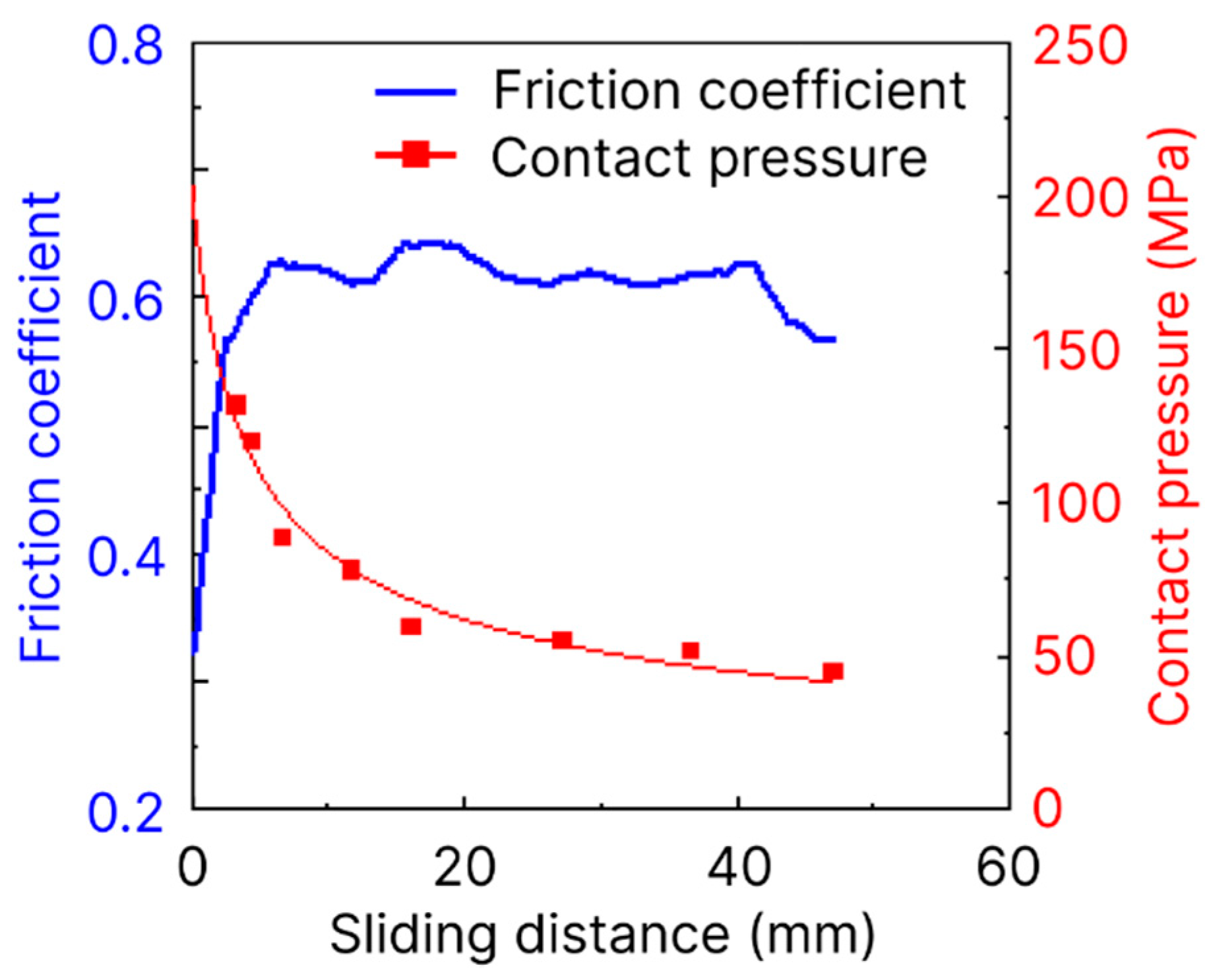
3.1. Friction Coefficient Evolution

Figure 3 shows the evolution of the friction coefficient and contact pressure between the AA6082 pin and G3500 strip during the dry sliding distance. The friction coefficient was approximately 0.32 at the beginning of the sliding, then it sharply increased to approximately 0.62 at the sliding distance of around 7 mm. This period is well known as the ‘running in state’ when the aluminum transfer layer is formed on the tool surfaces. Then the friction coefficient remained within a steady range varying from approximately 0.55 to 0.63 until the end of sliding, which is known as the ‘steady state’, when the morphology variation in the interface is relatively stable. This indicates that the dynamic equilibrium in the wear particles or third body and a saturated material transfer was achieved. Thereby, the distance that was required to reach the ‘steady state’ from the initial ‘running in state’ was approximately 7 mm in the present work.
As shown in Figure 3, the contact pressure has a negative correlation with the friction coefficient during the sliding process, since the evolution of the contact pressure continuously decreased while the friction coefficient basically increased as the sliding proceeded. Within the ‘running in state’, there was a rapid worn-off as the soft AA6082 pinhead slid against the harder G3500 strip, as demonstrated by the increase in actual contact diameter listed in Table 1. During this stage, the contact pressure rapidly decreased to approximately 75 MPa. Then the decreasing trend slowed down and reached approximately 50 MPa at the end of sliding.

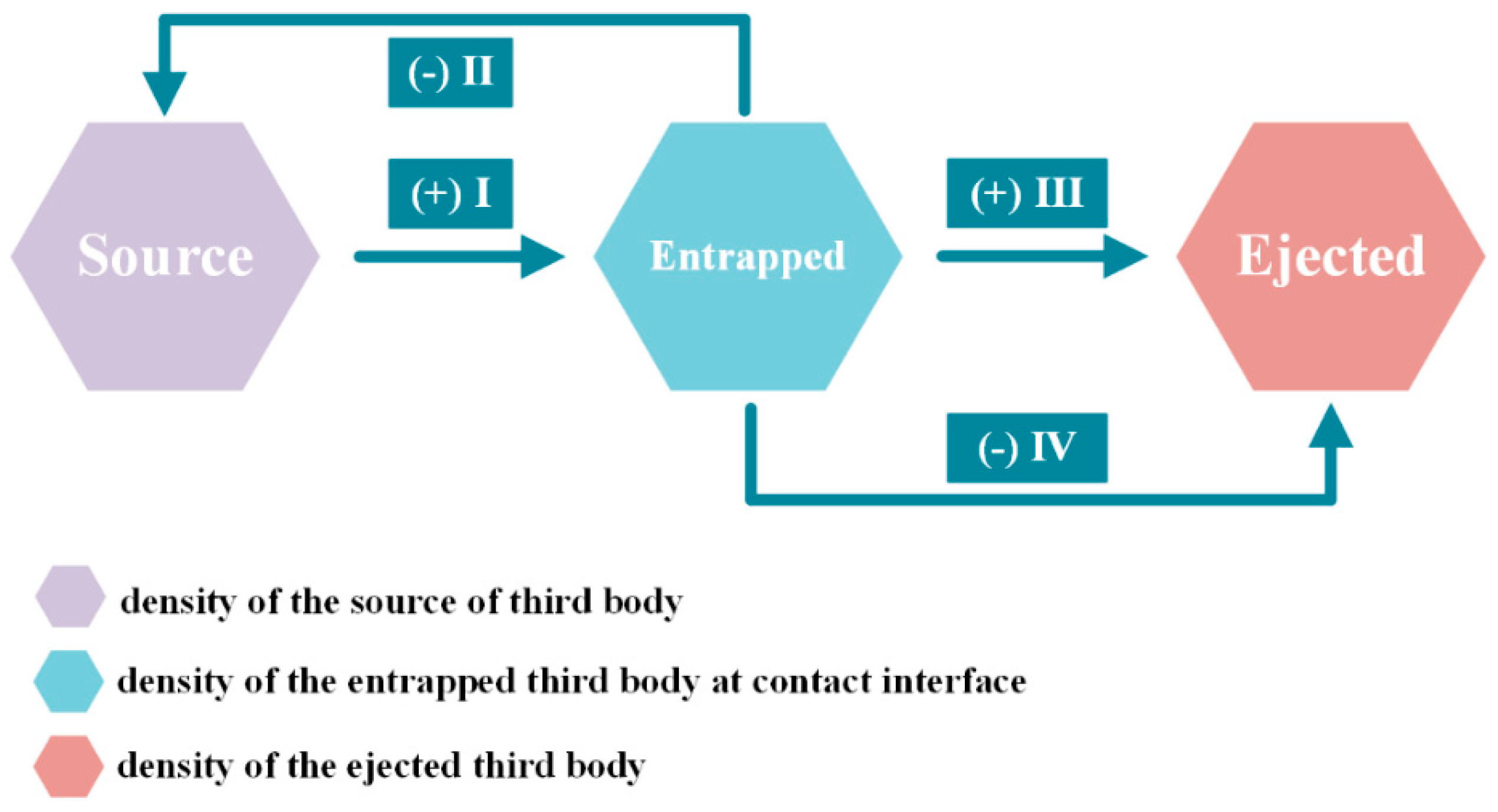
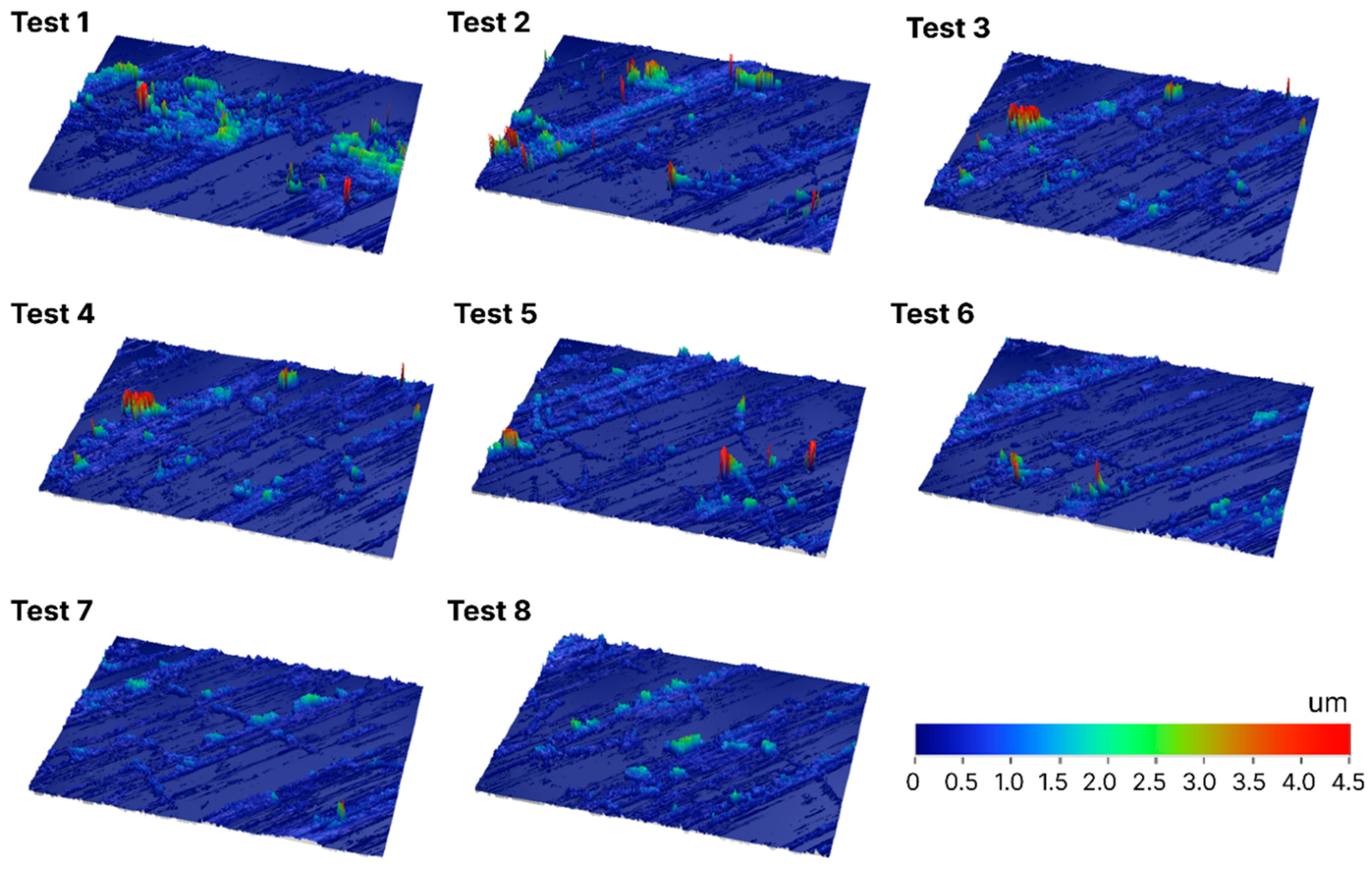
3.2. Aluminum Transfer Layer Analysis

Figure 4 shows the evolution of the galling area fraction compared to the contact pressure between the AA6082 pin and G3500 strip during the dry sliding. Both the contact pressure and the galling area fraction decreased as the sliding distance increased. The contact pressure rapidly decreased within the ‘running in state’, then it slightly decreased to approximately 50 MPa at the end of sliding. Meanwhile, the galling area fraction decreased sharply from approximately 8% to 6% within the ‘running in state’. Then it continuously decreased to around 3% until the end of sliding.
Figure 5 shows the surface topography analysis of the wear track with different sliding distances under dry sliding condition. The galling area fraction was determined utilizing the image processing technology. As can be seen in this figure, the maximum asperity in the wear track decreased as the sliding distance increased (from tests 1 to 8). This indicates that the galling area fraction has a positive correlation with the contact pressure, indicating that a higher contact pressure would lead to higher galling area fraction. The decrease in contact pressure may lead to the self-healing in the morphology where the saturated galling area decreased.
During the period of the ‘running in state’, the aluminum pinhead was directly in contact with the G3500 cast iron strip that caused significantly increasing friction due to the adhesion and ploughing between the surface asperities [1]. Thereby, the relative sliding between the AA6082 and G3500 sheared the contact junctions and removed the soft aluminum asperities, which resulted in the detachment of the solid aluminum and the formation of loose wear particles. With the combined effects of the significant contact pressure and shearing force, and the surface defects and the high adhesion characteristic of aluminum, these wear particles are likely to adhere to the tool surface and form aluminum lumps, which further accumulates as an aluminum transfer layer. Transfer and back-transfer mechanism may exist among the wear particles, solid aluminum and transfer lumps of aluminum. The ejection of wear particles may also be active through the entire sliding process, even when the steady state is reached.

4. Conclusions

In the present research, we investigated the friction coefficient evolution and galling behaviour between the AA6082 pin and G3500 cast iron strip under the dry sliding condition using the automated tribo-testing system, Tribo-Mate. The rapid increase of the friction coefficient at the running-in stage under dry sliding contact condition was due to the formation of aluminium transfer layer between the contact surfaces. The friction coefficient stabilized at a high value level indicating that the dynamic equilibrium was achieved between the generation and ejection of loose wear particles or third body. The contact pressure variation would disequilibrate and rebuild the dynamic balance between generation and ejection, thus affecting the saturated galling area. The galling area fraction has a positive correlation with the contact pressure, suggesting that the higher contact pressure would lead to the higher galling area fraction. The decrease of contact pressure likely led to a period of self-healing of the morphology where saturated galling area decreased.

Author Contributions

Conceptualization, L.W., X.Y. and H.L.; methodology, X.Y., Y.Z. and H.L.; validation, X.Y. and Y.Z., formal analysis, X.Y. and H.L.; writing—original draft preparation, H.L.; writing—review and editing, X.Y. and L.W.; visualization, X.Y. and H.L.; supervision, L.W. All authors have read and agreed to the published version of the manuscript.

Funding

This research received no external funding.

Institutional Review Board Statement

Not available.

Informed Consent Statement

Not available.

Data Availability Statement

Data available on request.

Acknowledgments

The authors are grateful to Zbigniew Kowalewski, Elżbieta Pieczyska, Mateusz Kopec and all the members of the conference committee of 19th ICEM 2022 for their great efforts on the conference organization work.

Conflicts of Interest

The authors declare no conflict of interest.

References

  1. Yang, X.; Hu, Y.; Zhang, L.; Zheng, Y.; Politis, D.J.; Liu, X.; Wang, L.L. Experimental and modelling study of interaction between friction and galling under contact load change conditions. Friction 2022, 10, 454–472. [Google Scholar] [CrossRef]
  2. Hu, Y.; Wang, L.; Politis, D.J.; Masen, M.A. Development of an interactive friction model for the prediction of lubricant breakdown behaviour during sliding wear. Tribol. Int. 2017, 110, 370–377. [Google Scholar] [CrossRef] [Green Version]
  3. Hu, Y.; Zheng, Y.; Politis, D.J.; Masen, M.A.; Cui, J.; Wang, L. Development of an interactive friction model to predict aluminum transfer in a pin-on-disc sliding system. Tribol. Int. 2019, 130, 216–228. [Google Scholar] [CrossRef]
  4. Ghiotti, A.; Simonetto, E.; Bruschi, S. Influence of process parameters on tribological behaviour of AA7075 in hot stamping. Wear 2019, 426, 348–356. [Google Scholar] [CrossRef]
  5. Yang, X.; Zhang, Q.; Zheng, Y.; Liu, X.; Politis, D.; El Fakir, O.; Wang, L. Investigation of the friction coefficient evolution and lubricant breakdown behaviour of AA7075 aluminium alloy forming processes at elevated temperatures. Int. J. Extrem. Manuf. 2021, 3, 025002. [Google Scholar] [CrossRef]
  6. Dohda, K.; Yamamoto, M.; Hu, C.; Dubar, L.; Ehmann, K.F. Galling phenomena in metal forming. Friction 2021, 9, 665–685. [Google Scholar] [CrossRef]
  7. Yang, X.; Liu, X.; Liu, H.; Politis, D.J.; Leyvraz, D.; Wang, L. Experimental and modelling study of friction evolution and lubricant breakdown behaviour under varying contact conditions in warm aluminium forming processes. Tribol. Int. 2021, 158, 106934. [Google Scholar] [CrossRef]
  8. Wang, L.; He, Y.; Zhou, J.; Duszczyk, J. Effect of temperature on the frictional behaviour of an aluminium alloy sliding against steel during ball-on-disc tests. Tribol. Int. 2010, 43, 299–306. [Google Scholar] [CrossRef]
Figure 1. Schematic illustration of material transfer loop during metal forming. Flows I & III represent the outputs, flows II & IV represent feedbacks.
Psf 04 00010 g001
Figure 2. Schematic diagram of the Tribo-Mate configuration [7].
Psf 04 00010 g002
Figure 3. Evolutions of friction coefficient and contact pressure between the AA6082 pin and G3500 strip during dry sliding.
Psf 04 00010 g003
Figure 4. Evolution of contact pressure and galling area fraction during dry sliding.
Psf 04 00010 g004
Figure 5. Surface topography analysis of the wear track with different sliding distances (tests 1–8) under dry sliding condition.
Psf 04 00010 g005
Table 1. Friction test matrix under varying sliding conditions.
Test No.Sliding Distance
(mm)
Normal Load
(N)
Actual Contact Diameter
(mm)
Contact Pressure
(MPa)
13.3100.311131.6
24.3100.326119.8
36.6100.37988.6
411.7100.40378.4
516.0100.46359.4
627.1100.4855.3
736.6100.49651.7
847.0100.5345.3
Publisher’s Note: MDPI stays neutral with regard to jurisdictional claims in published maps and institutional affiliations.

