Abstract
Wind energy is an important renewable energy source. Rotor main bearings are critical components of wind turbines since a faulty main bearing leads to downtime and high repair costs. Operational expenditures amount to 32% of wind energy costs. The use of plain bearings as main bearings can potentially reduce these costs. Plain bearings with segmented sliding elements can be repaired up-tower without dismantling the drivetrain, as damaged segments can be exchanged individually. One such segmented plain bearing design is the conical plain bearing design called FlexPad. For the FlexPad, proof of concept was achieved for the 1 MW range during previous studies. Modern wind turbines—especially for offshore deployment—have increased in size significantly compared with their predecessors. The goal of current studies is to transfer the FlexPad design towards a main bearing unit at a market relevant scale of 8.5 MW. In this work, the identified scaling challenges are presented. A FlexPad model scaled to the 8.5 MW range is presented to illustrate the challenges. The bearing load components, such as radial forces and torque, increase on different scales with increasing rotor size leading to changed load characteristics with increasing size. Increased rotor weight and bearing diameters result in an increase in the breakaway torque required to start turbine rotation. This breakaway torque can exceed the torque generated by the turbine at starting wind speeds. The generally increased loads necessitate stiffer sliding segments leading to the increased weight of the segments, which hampers the ability to easily exchange segments.
1. Introduction
Electrical energy generated by wind turbines (WT) is crucial for the future energy supply. The European Union aims to increase its renewable energy production to 40% by 2030 [1]. Germany aims to increase its renewable electricity production to 80% by 2030 [2]. In order to incentivise the setup of more WTs in the future, costs have to decrease further. One important share for WT operational expenditure is the costs due to maintenance and repair. Operational expenditures amount up to 32% of wind energy costs [3]. WT main bearings are an essential component of the drivetrain. Main bearings support the weight of the rotor and the loads caused by the rotor due to the wind. Rated power, as well as the rotor diameters of installed WTs in Europe and the US, have been increasing over the past years [4,5]. The average rated power increased from 790 kW in 1998 to 3.3 MW in 2018, with rotor diameters increasing from 48 m to 118 m on average [6,7]. In 2022, the average turbine size for newly installed wind turbines in Germany was 4.5 MW for onshore and 9 MW for offshore turbines [8]. This drastic increase in size leads to an increase in loads for the main bearing. Currently, WT main bearings suffer from low reliability and experience failure rates of up to 30% [9]. Commercially available main bearings exclusively use rolling elements [10,11,12,13,14,15,16]. A failed main bearing leads to high repair costs [17,18,19], which overall constitute a significant portion of operational costs for wind turbines [3,20,21]. The high costs are caused by the elaborate process of dismounting the rotor to exchange the bearing and the subsequent long downtime.
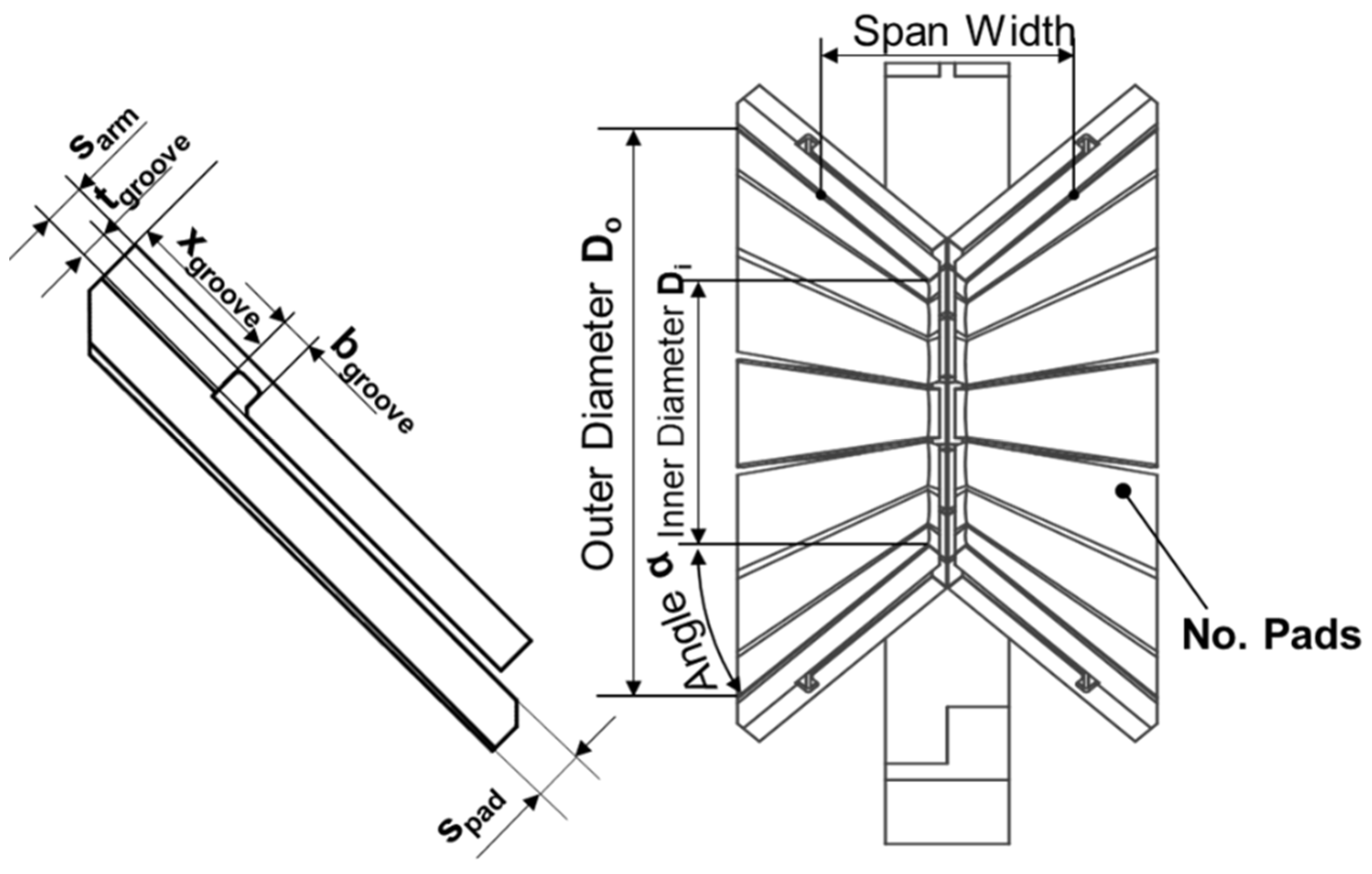
One approach to reduce these costs and increase the reliability is the development of plain bearings for WT main bearings. Segmented plain bearings can be repaired up-tower without the dismounting of the rotor because the sliding segments can be exchanged individually. One plain bearing concept (FlexPad) was developed by the Chair for Wind Power Drives in the WEA-GLiTS research project. The main objective of this research project was to develop a material concept for plain bearings for the use as main bearings in wind turbines. A thermal-sprayed coating has been developed. The material is based on a cobalt alloy and features solid lubricants incorporated into the matrix. However, in addition to the development of a surface material, various plain bearing designs were investigated, with the FlexPad design emerging as the best solution [22]. The FlexPad design is a double conical plain bearing with individual sliding segments. The segments are mounted to the housing with a flexible support structure that allows the segments to follow the movement of the shaft. This allows for the sliding surfaces to remain parallel to the shaft during operation, therefore maintaining a large area on which the lubrication film can form. Due to this flexibility, a better pressure distribution among the segments can be achieved and edge wear—contact between the segment edge and the shaft without the formation of a lubrication gap—is drastically reduced [22,23]. The shape of the design is mostly determined by ten key parameters (see Figure 1). The shape of the two cones is determined by the inner and outer diameter, the angle alpha and the span width between the rotor and generator side sliding segments. The design of the sliding segments and the support structure is defined by their respective thicknesses and the position and depth of the groove. For more detailed descriptions of the FlexPad design, the previous publications are referenced here [22,23,24,25]. The FlexPad bearing was designed and validated as a main bearing for the Vestas V52, a 750 kW WT. To make use of the FlexPad concept for WT at a market relevant scale, the concept needs to be scaled to larger turbine sizes. The objective of the project NextMBU is to scale the FlexPad concept towards market relevant size (rated power of about 8.5 MW). The goal of this paper is to evaluate the established FlexPad concept regarding its scalability and to highlight the challenges arising from this scaling process.

Figure 1.
Schematic of the FlexPad concept with its key design parameters.
2. Approach
In the following chapter, the methods employed for the determination of the design load case, the simulation setup and the scaled bearing design are described. The scaled bearing design was derived using estimated load data, determined based on publicly available data sets for WTs of varying sizes. Based on the estimated loads, an initial bearing design was created using the simulation toolchain described in [26]. With the initial design, conclusions can be drawn regarding the challenges arising from the proposed scale increase.
2.1. Load Scaling
Main bearing loads generally increase with the rated power of the WT due to the increase in rotor diameter. The relevant load components of the main bearing are the thrust , the radial loads and the bending moment . The radial loads are dominated by their vertical component which stems from the weight of the rotor. The horizontal component of the radial loads is comparatively negligible except for extreme wind shear situations. The same is true for the bending moment. The load components increase on different scales with the rated power. Manwell [13] describes simple relations between the load components and the rotor diameter. The generated power is proportional to the rotor area and thus to the diameter squared.
The same applies to the thrust, as both scale with the area swept by the turbine blades.
The radial loads are proportional to the weight of the rotor. Assuming geometric similarity, the volume of the blades increases cubically with the diameter. With the material being unchanged, the weight is proportional to the volume and therefore the diameter cubed.
The bending moment is dependent on the rotor weight and moments caused by the thrust forces. As described, the thrust scales quadratically with the diameter. The thrust force multiplied by a factor dependent on the length of the blades results in the bending moment. Therefore, the bending moment scales with the diameter cubed.
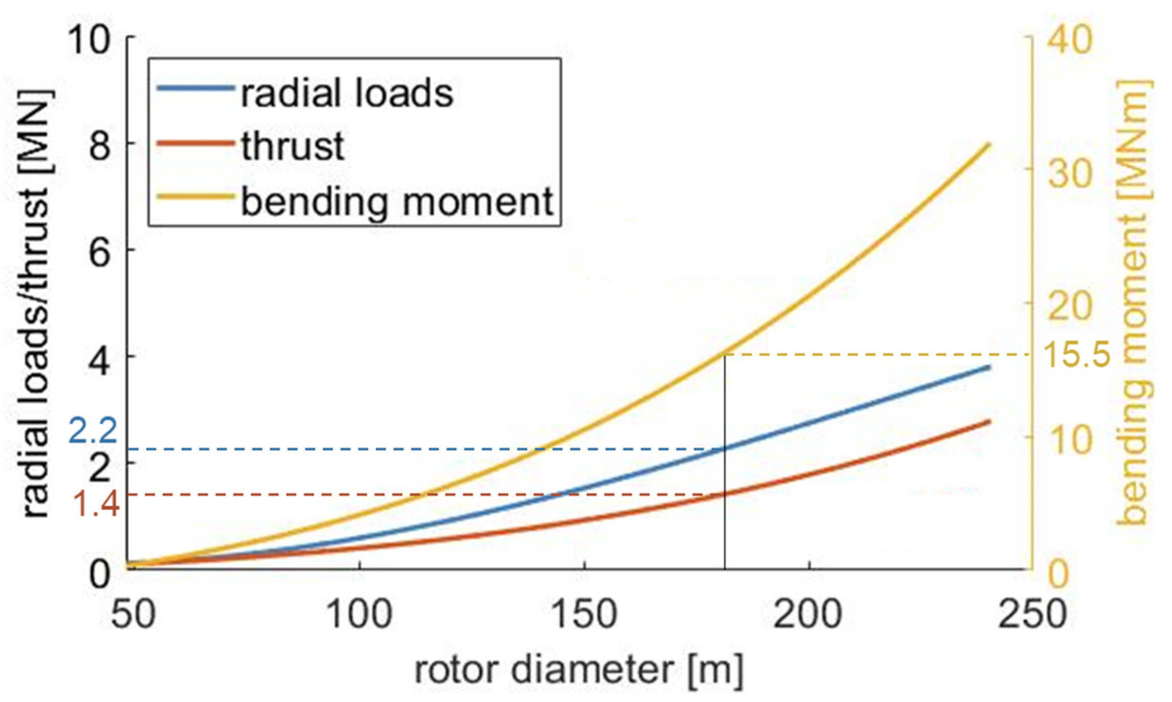
Based on these relationships between loads and the turbine dimensions, rough estimations of the main bearing loads are possible. Figure 2 shows the relation between thrust, radial forces, bending moment, and the rotor diameter of a WT. The relationship was derived based on ten load data sets (simulation and field data) of WTs in the power range of 750 kW up to 15 MW with rotor diameters of 48 m to 240 m. No crosswinds were considered. With increasing rotor diameter, the radial forces and especially the bending moments increase their dominance compared with the thrust. For a turbine with a rated power of 8.5 MW, the estimated loads are listed in Table 1 and are highlighted in Figure 2. The further bearing design was conducted using these load conditions.
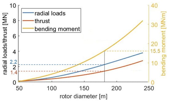
Figure 2.
Main bearing loads in relation to the rotor diameter (loads for 8.5 MW are highlighted).

Table 1.
Estimated rotor diameter and loads for turbines in the 8.5 MW range.
In short, main bearing loads increase disproportionately with turbine size. Comparing the estimated bending moment between a 1 MW turbine and a 10 MW the moment increases by a factor of 25, while the thrust forces only increase by a factor of eleven. The radial loads for 1 MW to 10 MW increase by a factor of 16.25. This poses challenges for the up-scaling of the established FlexPad concept. Firstly, the general load increase leads to necessary design adaptations that negatively affect serviceability (see Section 3.1). Secondly, the change in load characteristics (high radial loads and bending moments) hampers the starting ability of the turbine at low wind speeds (see Section 3.2).
2.2. Simulative Approach
The insights of this work are derived from elasto-hydrodynamic-multi-body (EHD-MB), finite element (FE) and multi-body (MB) simulations. For the EHD simulations, the software FIRST of the IST mbH was used. First is a multibody system simulation software that focuses on tribological components. The EHD simulation setup is identical to the ones presented by Rolink et al. [24,26]. The simulation toolchain was initially presented in [24] and the sensitivity of the FlexPad to geometrical design changes was investigated in [26]. The modelling approach used was validated in the course of the WEA-GliTS [22] and FlexPad research project with the final report of the FlexPad project being published by the end of 2023.
The goal of the simulations was to assess the hydrodynamic performance of the bearing design under nominal conditions. The model includes the sliding segments, their support structure and the bearing shaft. Using this setup, interactions between the bearing components can be examined. For the model creation and iterative bearing design, the toolchain described in [26] was used. The toolchain encompasses the automatic generation of the bearing geometry according to the assigned parameters. The FE model creation, the generation of a modal reduction and the formation of the EHD model are performed automatically. The bearing’s performance under the loads described is examined in Section 2.1. Model validation on a test bench will be carried out as part of the NextMBU project.
2.3. Scaled FlexPad Design
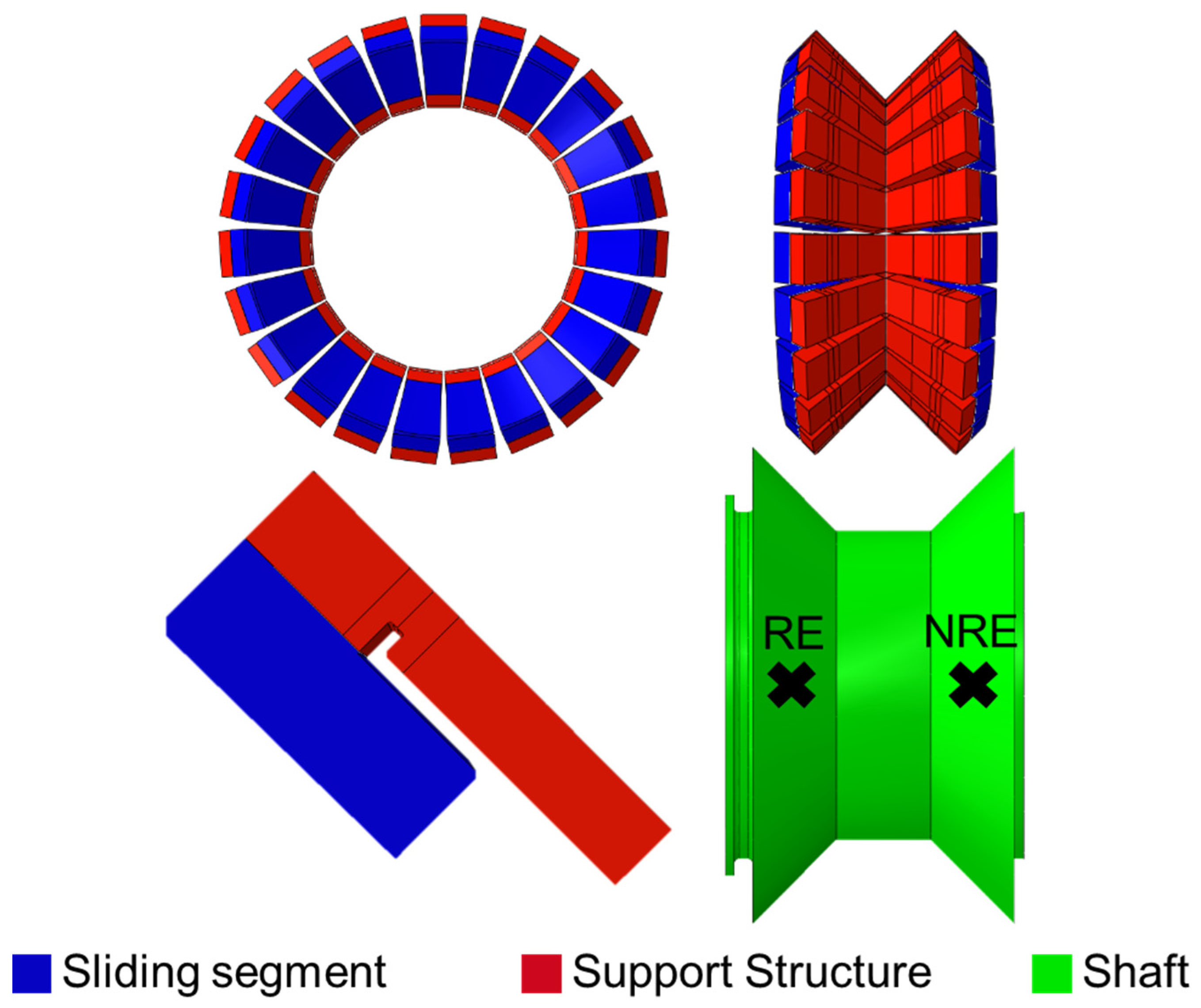
Based on the loads for an 8.5 MW WT, an initial scaled design was derived. The design was reached via a manual iterative design process. The geometrical boundary conditions are based on the test bench assembly space for a planned validation test. Based on these, a design was devised and subsequently improved using parameter studies like [26]. The initial design goal was to create a functional initial design, which is able to support the design load conditions fully hydrodynamically. The current design stage does not reflect a finished and comprehensively optimized design. In Figure 3, the scaled design is shown with its dimensions listed in Table 2. The sliding segments are highlighted in blue, the flexible support structure (or arms) in red and the shaft in green. The scaled bearing design retains the symmetrical double cone shape of the original FlexPad. As with the original FlexPad, the design is characterized by a narrow span width, a 45° angle between the sliding surface and the shafts’ rotational axis and the double flexible support structure design. The outer and inner diameters are naturally increased. Also increased is the component thickness for the support structure and sliding segments. Both increases result from the increased loads and will be further discussed in the following chapter.
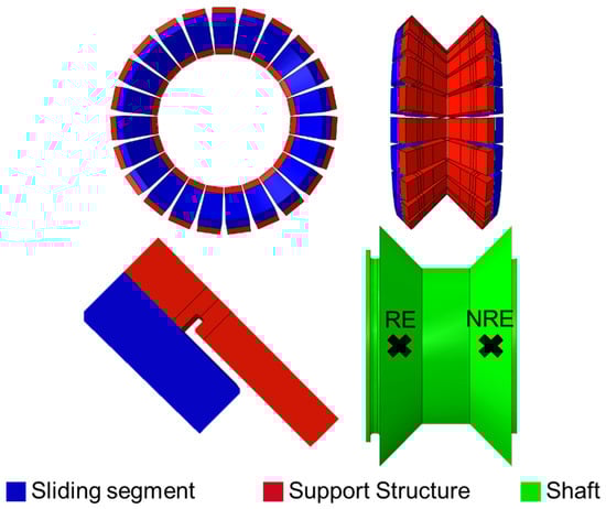
Figure 3.
Scaled FlexPad bearing (RE = rotor end; NRE = non rotor end).
Table 2.
Relevant parameters of original FlexPad design and the scaled FlexPad design.
The bearing’s performance is examined for the determined loads for an 8.5 MW WT at an operational speed of 11 rpm. Table 3 shows the EHD-simulation results for the initial bearing design. The designed bearing is able to hydrodynamically carry the applied load. Hydrodynamic friction power loss constitutes 0.35% of the rated power. The “maximum specific pad pressure” is defined as the normal forces acting on the most highly loaded sliding segment divided by its area. The determined value is 47% smaller than the surface material thresholds of up to 30 MPa [22]. The maximum pressure observed is significantly (39.7%) higher than the determined material threshold of 180 MPa [22]. The pressure area (=percentage of area which experiences pressures above 0.1 MPa) is smaller than in previous designs [24]. This indicates a poor utilisation of the bearing’s surface and needs to be optimised in future designs.
Table 3.
Simulation results for the initial bearing design under the determined 8.5 MW loads.
The initial bearing design is a crucial first step for identifying future design challenges or even conflicts. Regarding the high maximum pressure, Rolink et al. have shown in [24] that a severe reduction in maximum pressure is possible through the individual adjustment of design parameters.
3. Results
Two initial scaling challenges for the conical sliding bearing concept have been identified and will be discussed in the following. Firstly, the effects of scale in the segment size caused by the load increase are discussed. Increased segment sizes lead to handling restrictions during service. Secondly, the effects caused by the changed load characteristics are discussed. The increasingly dominant rotor weight and its resulting moment lead to higher loads during turbine start. These loading conditions may hamper the ability of the turbine to start at usual cut-in wind speeds. This work makes no claim regarding the completeness of the scaling challenges as others may be discovered and described in the future.
3.1. Segment Weight Increase and Restricted Servviceability
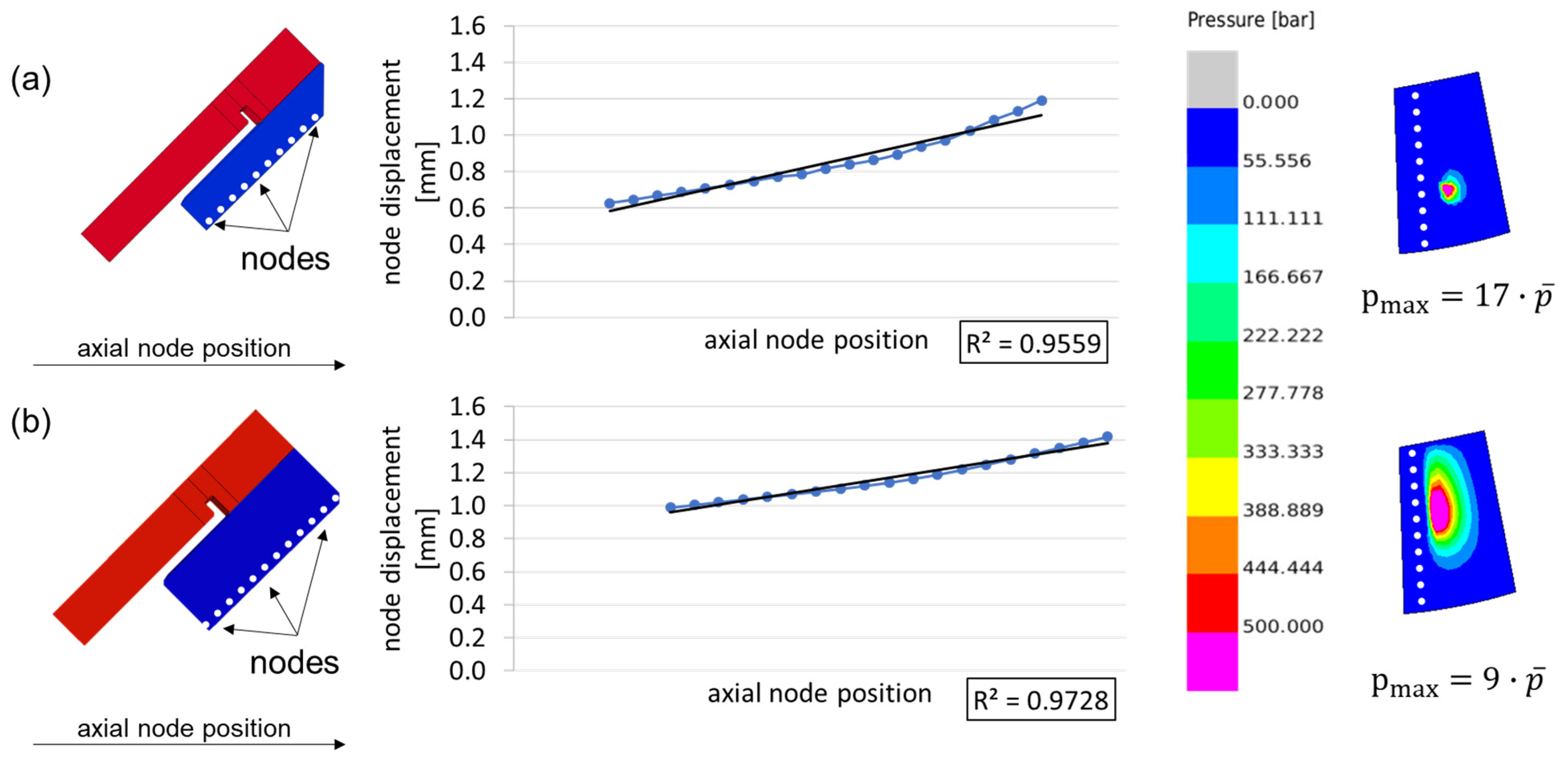
The key advantage of using plain bearings as WT main bearings is their segmentation and thus improved serviceability. It was demonstrated that the FlexPad sliding segments can be manually exchanged in the case of damage [22,23,25]. However, WT main bearings in the 5 MW to 10 MW range experience significantly higher loads than the initial FlexPad prototype. This necessitates design adjustments to the FlexPad prototype. One such adjustment is shown in Figure 4. The FlexPad concept is designed to bend in its flexible support structure. This allows the sliding segment to remain parallel to the shaft and thus constitute a large area for pressure build up. Bending in the sliding segments, however, is disadvantageous. On the left-hand side, Figure 4 shows two different bearing designs with varying sliding segment (in blue) thickness. The sliding segment thickness is 100 mm for design (a) and 150 mm for design (b). The support structures (in red) and the overall bearing design are identical for both variants. In the middle, the displacement of the sliding segment’s surface is shown in comparison with its initial position. Additionally, the root mean square error (R²) of both sliding segments’ deviation from a straight line is shown. On the right-hand side, the corresponding pressure build up is depicted for the most highly loaded sliding segment. For the two designs, the sliding segments show different displacement behaviours. For both designs, the sliding segments are not displaced perfectly parallel with regards to the movement of the shaft. Thus, both designs slightly bend under the applied pressure. For the design (a), the bending curvature is more pronounced. This is also shown in the root mean square error of both sliding segments’ deviations from a straight line, which is greater by 1.69% for design (a). The curvature of design (a) leads to a significantly different hydrodynamic pressure build-up. The highly loaded area is small compared with the segment surface. Its position corresponds roughly to the apex of the sliding segments curvature. Here, the lowest oil film heights and the highest pressures are reached. The remaining sliding segment surface carries barely any load. For design (a), solid body friction does occur. Design (b) shows an even pressure distribution over nearly the whole sliding surface. This also manifests itself in the determined maximum pressure.
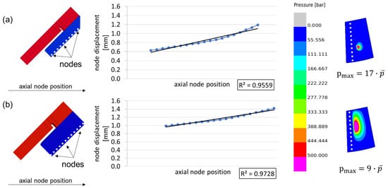
Figure 4.
Effect of segment thickness on deformation and hydrodynamic pressure build-up.
Figure 4 illustrates that high stiffness is needed for the sliding segments. Thus, thicker sliding segments are needed. From this necessity, two issues arise. Firstly, the increased thickness results in increased costs, as more material is needed. The second issue is the weight of the sliding segments. The weight increased from 12 kg for the bearing developed in WEA-GLiTS to 125 kg for the initial scaled design. The sliding segments of the scaled FlexPad design can therefore no longer be exchanged without the use of an onboard crane.
One approach to overcome this conflict would be an increase in span width to reduce loads acting on the main bearing surfaces. Rib structures for the sliding segments could be introduced to reduce weight. A higher number of segments would also automatically reduce the weight off of individual sliding segments. All three approaches need to be integrated into future bearing designs but are also limited by the feasibility of the resulting concepts.
3.2. Higher Starting Loads and Resulting Breakaway Torque
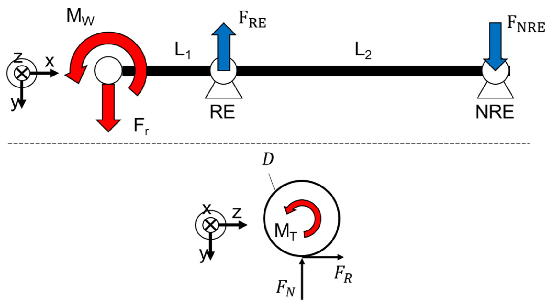
Hydrodynamic plain bearings need to overcome boundary friction and mixed friction regimes before they enter fully into hydrodynamic friction and wear-free load bearing operation. Boundary friction is solely dependent on the friction coefficient (which in turn is dependent on a multitude of factors) and the normal forces acting on the surface. The dominant forces on the rotor main bearing for large scale WT are the radial force and the bending moment. Both are dominated by the rotor weight, especially during stand-still. The challenge can be demonstrated with a relatively simple static, mechanical model of a main shaft with two bearing locations (see Figure 5; rotor loads indicated by red arrows). The main bearing halves of the FlexPad design are depicted as fixed bearings for the RE and NRE. The lower half of Figure 5 shows a simplified depiction of a radial plain bearing and the acting forces.
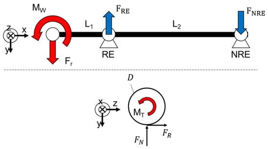
Figure 5.
Simplified static mechanical model including the load scenario for a WT rotor bearing system.
Equation (5) shows the static force equilibrium in the y-direction for the simplified load scenario. The thrust forces are neglected. The load carried by the RE bearing is equal to the sum of the radial rotor forces and the force of the NRE bearing.
Equation (6) shows the static moment equilibrium (around the z-axis) at the RE bearing for the simplified load scenario. The amount of radial force carried by the NRE bearing is determined by the distances and . For an increasing span width , the NRE forces are reduced. An infinite increase in span width reduces the NRE forces to zero. Assuming these idealised conditions, the theoretically possible minimum RE forces can be approximated.
Thus, the resulting forces in the y-direction on the RE bearing can be no smaller than the radial loads applied via the rotor.
Equation (8) shows the minimum necessary torsional moment or breakaway torque to instigate the rotation of a rotor with 140 m diameter. The respective load is derived from the relationships described in Section 2. The minimum torsional moment is a function of the radial forces, the friction coefficient and the bearing diameter. Using the estimated loads, the scaled FlexPad bearing dimensions and the friction coefficient of the material used in the previous FlexPad designs [22], the minimum breakaway torque can be estimated (see Equation (8)).
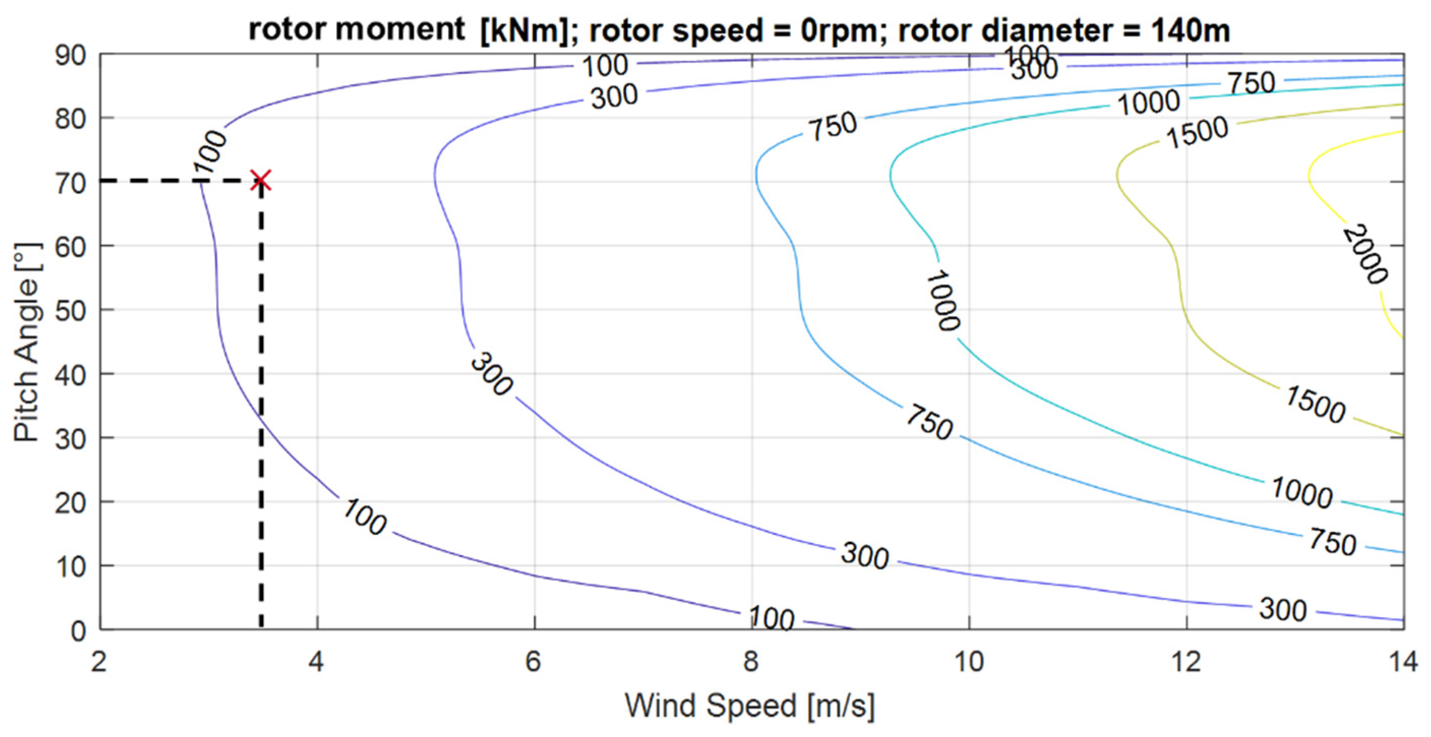
WTs generate torque via the lift generated by their blades. The producible torque is lowest for a still-standing turbine [11,12]. To assess the torque a turbine can produce for still-standing turbine blades an aero-elastic load calculation with a detailed elastic multibody simulation-model of a WT based on the works of Loriemi et al. [27] with a generic rotor design was performed. The reference rotor has a diameter of 140 m. The resulting torque for different wind speeds and pitch angles is depicted in Figure 6. The minimum necessary wind speed and pitch angle for a rotor torque of 139 kNm are highlighted. As can be seen, the generated rotor torque naturally increases with wind speed. Regarding the blade pitch, the most torque can be generated for pitch angles between 40° and 80°.
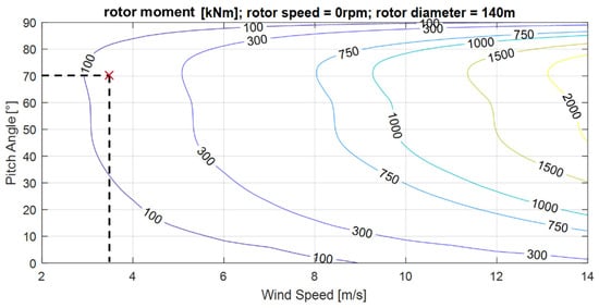
Figure 6.
Generated turbine torque for different wind speeds and blade pitch angles (pitch angle and wind speed for 139 kNm torque are highlighted).
Most WTs in the 140 m diameter range have cut-in wind speeds between 2.5 m/s and 3.0 m/s [28]. At 3 m/s, the reference turbine is roughly able to produce 100 kNm of torque (see Figure 6). This is below the estimated minimum breakaway torque. As the normal forces are estimated towards their minimum, the actual cut-in wind speed would be even higher. Increasing the cut-in wind speed would lead to a reduced energy yield and needs to be avoided. Therefore, the breakaway torque needs to be reduced through bearing design changes.
A reduction in breakaway torque is possible through an adaptation of the bearing’s effective diameter, a change in surface material and a reduction in the loads via increased span widths. A load reduction through span width increase is a limited solution, as compact drivetrains and, therefore, compact bearing designs are looked upon more favourably for modern WTs. A reduction in the effective diameter seems to be a suitable solution as it would also decrease weight. However, with increasing size, WTs also operate with reduced rotational speeds [28]. To combat this reduction in rotational speed, large bearing diameters are needed to allow hydrodynamic pressure build-up in the bearing. This constitutes a design conflict. Plain bearing diameters need to be sufficiently large for hydrodynamic pressure build up but also small enough for the breakaway torque to not exceed the rotor torque at low wind speeds. Bearing diameter reductions are therefore limited. The remaining option is a change in surface material to reduce the friction coefficient.
Alternatively, a hydrostatic starting aid could be introduced. In doing so, the effective friction coefficient could be further reduced and thus allow for a turbine start at low wind speeds. However, this concept was hitherto not investigated for the FlexPad concept in particular, and plain bearings for WT main bearings in general, and needs to be explored in the future.
4. Conclusions
Plain bearings are a promising alternative to roller bearings as main bearings for WT. Due to their segmentation, individual segments can be exchanged in case of failure without dismantling the drivetrain. This would reduce downtime and repair costs. One such plain bearing concept is the FlexPad concept developed at the CWD. In this work, a scaled version of the FlexPad bearing for application in the 8.5 MW turbine range was presented. This first scaled bearing design already shows promising hydrodynamic performance but needs further optimization to be functional. The scaled design was used to identify key scaling challenges for plain bearings in multi megawatt WTs. With an increase in rated power, turbines increase in rotor diameter. This leads to an increase in the loads the main bearing needs to carry. Also, the individual load components caused by the rotor weight and wind forces increase on different scales with the rotor size and therefore the rated power. This leads to a change in load characteristic for large turbines, which experience high loads even during start-up.
The first scaling challenge is the segment size increase due to the increased loads. Especially for the FlexPad concept a high stiffness for the individual sliding segments is required. This leads to a significant weight increase. Therefore, the sliding segments of the scaled FlexPad design can no longer be exchanged by hand. To approach this challenge, higher segmentation and further weight optimization need to be explored in the future. The second scaling challenge stems from the increase in load during turbine start and is independent of the FlexPad concept. High loads and large bearing diameters lead to a considerable breakaway torque necessary to instigate rotation in the rotor. Depending on the plain bearing surface material, bearing diameter and further bearing design, the required breakaway torque may exceed the amount producible by the rotor at low wind speeds. As a reduction in loads is not possible and a reduction in bearing diameter is limited due to low rotational speeds, an exploration of new surface materials or hydrostatic starting aids remain as viable solutions.
Author Contributions
Conceptualization, J.E. and A.L.; methodology, J.E.; software, J.E. and A.L.; validation, J.E., T.J., A.R. and A.L.; formal analysis, J.E.; investigation, J.E.; resources, J.R. and G.J.; data curation, J.E.; writing—original draft preparation, J.E.; writing—review and editing, T.J., J.R. and G.J.; visualization, J.E.; supervision, A.R., T.J., J.R. and G.J.; project administration, J.E. and G.J.; funding acquisition, G.J. All authors have read and agreed to the published version of the manuscript.
Funding
This research was funded by the federal ministry for economic affairs and climate action. The grant number is 03EE3063A.
Institutional Review Board Statement
The study did not require ethical approval.
Informed Consent Statement
Not applicable.
Data Availability Statement
Not applicable.
Conflicts of Interest
The authors declare no conflict of interest.
References
- European Parliament: Amendments Adopted by the European Parliament on the Renewable Energy Directive; European Parliament: Brussels, Belgium, 2022.
- German Bundestag: Gesetz für den Ausbau Erneuerbarer Energien (Erneuerbare Energien-Gesetz—EEG 2023); German BundesTAg: Berlin, Germany, 2023.
- Stehly, T.; Duffy, P. 2021 Cost of Wind Energy Review; National Renewable Energy Lab.: Golden, CO, USA, 2023. [Google Scholar]
- Windeurope: Offshore Wind in Europe Key Trends and Statistics. 2019. Available online: https://windeurope.org/wp-content/uploads/files/about-wind/statistics/WindEurope-Annual-Offshore-Statistics-2019.pdf (accessed on 24 October 2023).
- Windeurope: Wind Energy in Europe Trends and Statistics. 2019. Available online: https://windeurope.org/wp-content/uploads/files/about-wind/statistics/WindEurope-Annual-Statistics-2019.pdf (accessed on 24 October 2023).
- Fraunhofer: Turbine Size. Available online: https://windmonitor.iee.fraunhofer.de/windmonitor_en/3_Onshore/2_technik/4_anlagengroesse/ (accessed on 11 January 2023).
- Wiser, R.; Bolinger, M.; Barbose, G.; Darghouth, N.; Hoen, B.; Mills, A.; Rand, J.; Millstein, D.; Jeong, S.; Mills, A.; et al. 2018 Wind Technologies Market Report; U.S. Department of Energy: Washington, DC, USA, 2018.
- Costanzo, G.; Bindley, G.; Cole, P. Wind Energy in Europe: 2022 Statistics and the Outlook for 2023–2027; Wind Europe: Brussels, Belgium, 2022. [Google Scholar]
- Edward, H.; Turnbull, A.; Feuchtwang, J.; Mcmillan, D.; Golysheva, E.; Elliott, R. Wind turbine main-bearing loading and wind field characteristics. In Wind Energy; Wiley: Hoboken, NJ, USA, 2019; Volume 22, pp. 1534–1547. [Google Scholar]
- Hart, E.; Clarke, B.; Nicholas, G.; Amiri, A.K.; Stirling, J.; Carroll, J.; Dwyer-Joyce, R.; McDonald, A.; Long, H. A review of wind turbine main bearings: Design, operation, modelling, damage mechanisms and fault detection. In Wind Energy Science; EAWE: Oldenburg, Germany, 2020; Volume 5, pp. 105–124. [Google Scholar]
- Hau, E. Windkraftanlagen; Springer: Berlin/Heidelberg, Germany, 2016. [Google Scholar]
- Heier, S. Windkraftanlagen; Springer Fachmedien: Wiesbaden, Germany, 2018. [Google Scholar]
- Manwell, J.F. Wind Energy Explained: Theory, Design and Application; Wiley: Hoboken, NJ, USA, 2009. [Google Scholar]
- Nejad, A.R.; Keller, J.; Guo, Y.; Sheng, S.; Polinder, H.; Watson, S.; Dong, J.; Qin, Z.; Ebrahimi, A.; Schelenz, R. Wind turbine drivetrains: State-of-the-art technologies and future development trends. In Wind Energy Science; Wiley: Hoboken, NJ, USA, 2022; Volume 7, pp. 387–411. [Google Scholar]
- Liu, Z.; Zhang, L. A review of failure modes, condition monitoring and fault diagnosis methods for large-scale wind turbine bearings. Meas. J. Int. Meas. Confed. 2020, 149, 107002. [Google Scholar] [CrossRef]
- Torsvik, J.; Nejad, A.R.; Pedersen, E. Main bearings in large offshore wind turbines: Development trends, design and analysis requirements. J. Phys. Conf. Ser. 2018, 1037, 42020. [Google Scholar] [CrossRef]
- Steffen, B.; Beuse, M.; Tautorat, P.; Schmidt, T.S. Experience Curves for Operations and Maintenance Costs of Renewable Energy Technologies. Joule 2020, 4, 359–375. [Google Scholar] [CrossRef]
- Mcgowan, E. Giant, turbine-installing ship is Dominion Energy’s $500M bet on U.S. offshore wind. Energy News Netw. 2022. [Google Scholar]
- Walgern, J.; Peters, L.; Madlener, R. Economic Evaluation of Maintenance Strategies for Offshore Wind Turbines Based on Condition Monitoring Systems. FCN Work. Pap. 2017. [Google Scholar] [CrossRef]
- Buck, B.H.; Langan, R. Aquaculture Perspective of Multi-Use Sites in the Open Ocean: The Untapped Potential for Marine Resources in the Anthropocene, 1st ed.; Springer International Publishing: Cham, Switzerland, 2017. [Google Scholar]
- Stehly, T.; Beiter, P.; Duffy, P. 2019 Cost of Wind Energy Review; National Renewable Energy Laboratory: Golden, CO, USA, 2019. [Google Scholar]
- Abschlussbericht: Thermisch Gespritzte Gleitlagerbeschichtungen für Hauptlager von Windenergieanlagen (WEA)—WEA Triebstrang und Oberflächentechnik, eng.: Final Report, WEA-GliTS; Technische Informationsbibliothek Hannover: Hannover, Germany, 2016.
- Schröder, T.; Jacobs, G.; Rolink, A.; Bosse, D. “FlexPad”—Innovative conical sliding bearing for the main shaft of wind turbines. J. Phys. Conf. Ser. 2019, 1222, 12026. [Google Scholar] [CrossRef]
- Rolink, A.; Jacobs, G.; Schröder, T.; Keller, D.; Jakobs, T.; Bosse, D.; Lang, J.; Knoll, G. Methodology for the systematic design of conical plain bearings for use as main bearings in wind turbines. Forsch. Im Ingenieurwesen 2021, 85, 629–637. [Google Scholar] [CrossRef]
- Schröder, T.N. Konisches Gleitlager für die Rotorlagerung einer Windenergieanlage, eng: Conical Sliding Bearing for the Rotor Main Bearing of a Wind Turbine; University Library RWTH Aachen: Aachen, Germany, 2021. [Google Scholar]
- Rolink, A.; Jacobs, G.; Pérez, A.; Bosse, D.; Jakobs, T. Sensitivity analysis of geometrical design parameters on the performance of conical plain bearings for use as main bearings in wind turbines. J. Phys. Conf. Ser. 2022, 2265, 32010. [Google Scholar] [CrossRef]
- Loriemi, A.; Jacobs, G.; Bosse, D. Estimation of Rotor and Main Bearing Loads Using Artificial Neural Networks; IOP Publishing Ltd.: Bristol, UK, 2022. [Google Scholar]
- Wind Turbines Database. Available online: https://en.wind-turbine-models.com/turbines?kwrange=4410%2C7110 (accessed on 4 May 2023).
Disclaimer/Publisher’s Note: The statements, opinions and data contained in all publications are solely those of the individual author(s) and contributor(s) and not of MDPI and/or the editor(s). MDPI and/or the editor(s) disclaim responsibility for any injury to people or property resulting from any ideas, methods, instructions or products referred to in the content. |
© 2023 by the authors. Licensee MDPI, Basel, Switzerland. This article is an open access article distributed under the terms and conditions of the Creative Commons Attribution (CC BY) license (https://creativecommons.org/licenses/by/4.0/).