
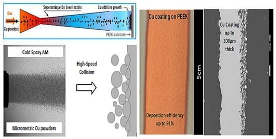
60% IACS Conductive Metal Coating on a Polymer Surface: Achievement of a Highly Efficient Additive Processing by Cold Spraying

Abstract
:
1. Introduction
2. High Pressure Cold Spray Metallization Conditions
2.1. Cold Spray Deposition Data
2.2. Deposition Efficiency Assessment
2.3. Coating Characterization Equipments
3. Results and Discussions
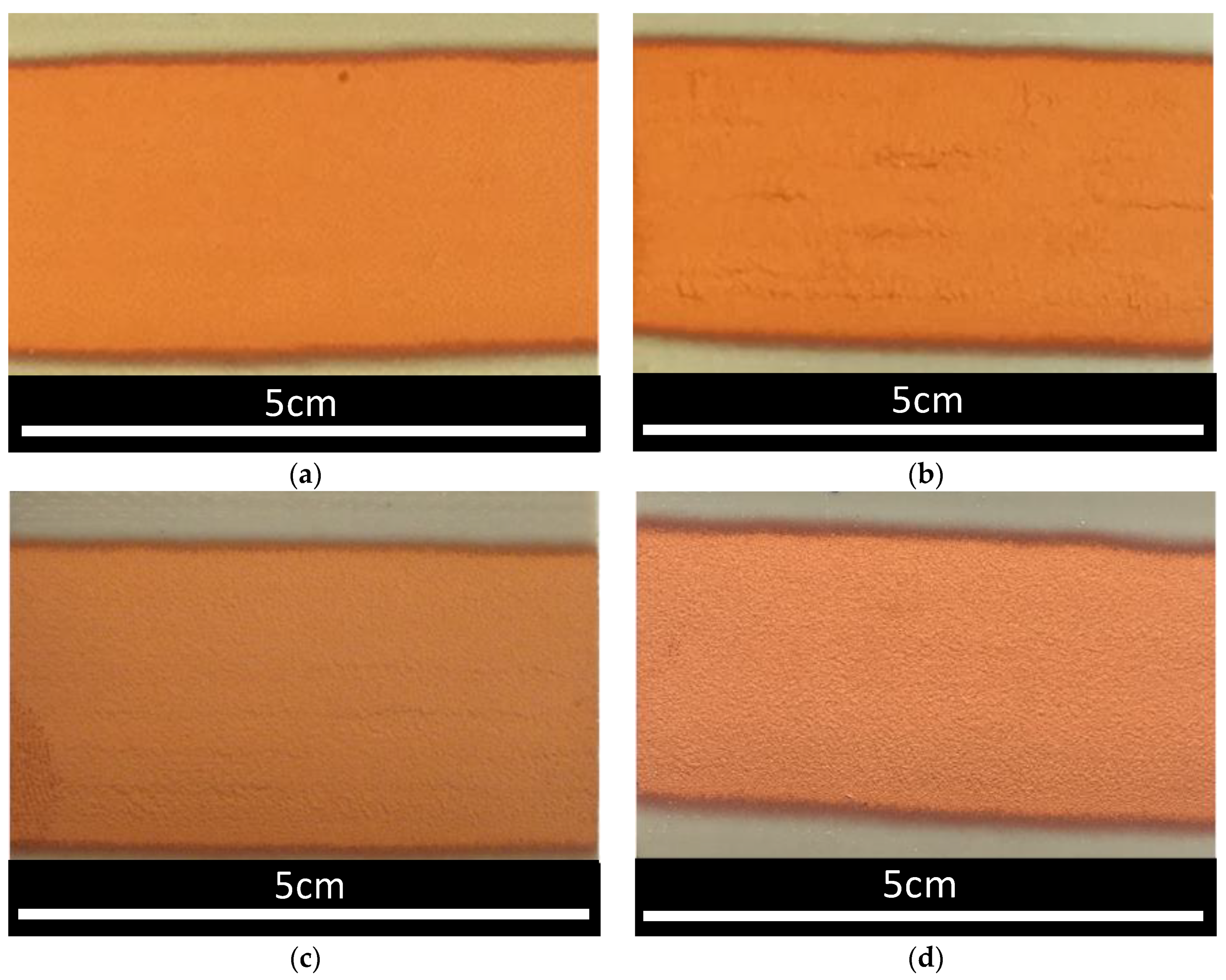
3.1. Empirical Approach for Optimizing the Cu Coating Growth onto PEEK
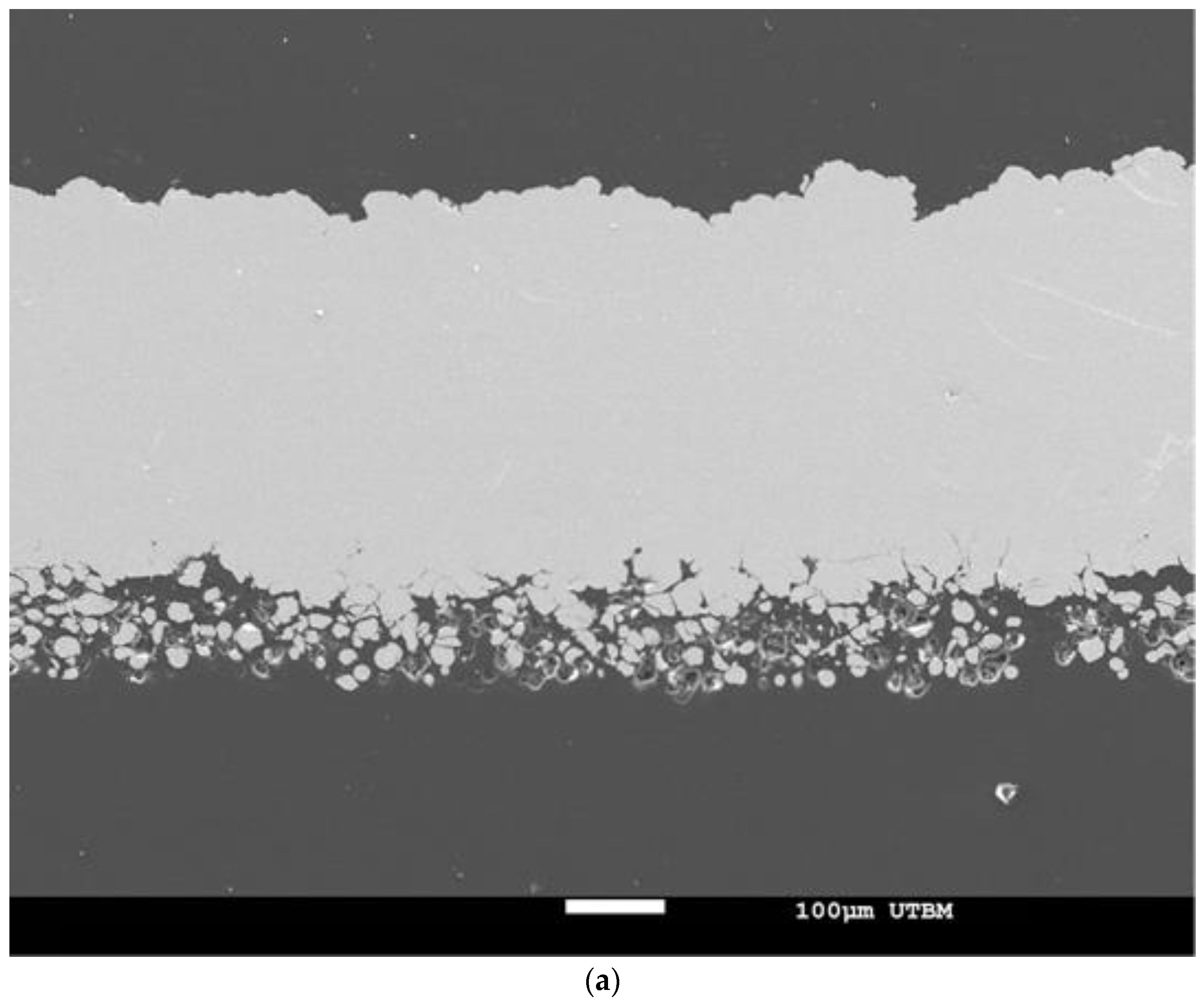
3.2. Features of the Cu Coating Obtained at High DE
4. Conclusions
Author Contributions
Funding
Conflicts of Interest
References
- Raoelison, R.N.; Verdy, C.; Liao, H. Cold gas dynamic spray additive manufacturing today: Deposit possibilities, technological solutions and viable applications. Mater. Des. 2017, 87, 133–266. [Google Scholar] [CrossRef]
- Moridi, A.; Hassani-Gangaraj, S.M.; Guagliano, M.; Dao, M. Cold spray coating: Review of material systems and future perspectives. Surface Eng. 2014, 30, 369–395. [Google Scholar] [CrossRef]
- Guo, D.; Kazasidis, M.; Hawkins, A.; Fan, N.; Leclerc, Z.; MacDonald, D.; Nastic, A.; Nikbakht, R.; Ortiz-Fernandez, R.; Rahmati, S.; et al. Cold Spray: Over 30 Years of Development Toward a Hot Future. J. Therm. Spray Technol. 2022, 31, 866–907. [Google Scholar] [CrossRef]
- Raoelison, R.N. Coeval Cold Spray Additive Manufacturing Variances and Innovative Contributions. In Cold-Spray Coating: Recent Trends Future Perspect, 1st ed.; Cavaliere, P., Ed.; Springer International Publishing: Cham, Switzerland, 2018; pp. 57–94. [Google Scholar]
- Wu, H.; Raoelison, R.N.; Zhang, Y.; Deng, S.; Hanlin, L. Cold Spraying of 3D Parts—Challenges. In Therm. Spray Coating, 1st ed.; Thakur, L., Vasudev, H., Eds.; CRC Press: Boca Raton, FL, USA, 2021. [Google Scholar]
- Schmidt, T.; Gärtner, F.; Assadi, H.; Kreye, H. Development of a generalized parameter window for cold spray deposition. Acta Mater. 2006, 54, 729–742. [Google Scholar] [CrossRef]
- Assadi, H.; Schmidt, T.; Richter, H.; Kliemann, J.-O.; Binder, K.; Gärtner, F.; Klassen, T.; Kreye, H. On Parameter Selection in Cold Spraying. J. Therm. Spray Technol. 2011, 20, 1161–1176. [Google Scholar] [CrossRef]
- Hassani-Gangaraj, M.; Veysset, D.; Nelson, K.A.; Schuh, C.A. In-situ observations of single micro-particle impact bonding. Scr. Mater. 2018, 145, 9–13. [Google Scholar] [CrossRef]
- Assadi, H.; Gärtner, F.; Stoltenhoff, T.; Kreye, H. Bonding mechanism in cold gas spraying. Acta Mater. 2003, 51, 4379–4394. [Google Scholar] [CrossRef]
- Della Gatta, R.; Perna, A.S.; Viscusi, A.; Pasquino, G.; Astarita, A. Cold spray deposition of metallic coatings on polymers: A review. J. Mater. Sci. 2021, 57, 27–57. [Google Scholar] [CrossRef]
- Feng, P.; Rokni, M.R.; Nutt, S.R. Depositing Aluminum onto PEKK Composites by Cold Spray. J. Therm. Spray Technol. 2020, 30, 385–393. [Google Scholar] [CrossRef]
- Gillet, V.; Aubignat, E.; Costil, S.; Courant, B.; Langlade, C.; Casari, P.; Knapp, W.; Planche, M.P. Development of low pressure cold sprayed copper coatings on carbon fiber reinforced polymer (CFRP). Surface Coat. Technol. 2019, 364, 306–316. [Google Scholar] [CrossRef]
- Viscusi, A.; Perna, A.S.; Astarita, A.; Boccarusso, L.; Caraviello, A.; Carrino, L.; Della Gatta, R.; Durante, M.; Sansone, R. Experimental Study of Cold Sprayed Metallic Coatings on Thermoplastic Matrix Composites. Key Eng. Mater. 2019, 813, 68–73. [Google Scholar] [CrossRef]
- Raoelison, R.N.; Lalu Koithara, L.; Costil, S. Cold spray coating of PEEK surface by copper deposition: Interfacial adhesion at high deposition efficiency and bonding strength. CIRP J. Manuf. Sci. Technol. 2021, 35, 63–68. [Google Scholar] [CrossRef]
- Raoelison, R.N.; Xie, Y.; Sapanathan, T.; Planche, M.P.; Kromer, R.; Costil, S.; Langlade, C. Cold gas dynamic spray technology: A comprehensive review of processing conditions for various technological developments till to date. Addit. Manuf. 2018, 19, 134–159. [Google Scholar] [CrossRef]
- Lalu Koithara, L.; Raoelison, R.N.; Costil, S.; Xie, X. High deposition efficiency and delamination issues during high-pressure cold spraying metallization of PEEK using spherical copper powders. Int. J. Adv. Manuf. Technol. 2020, 107, 4427–4436. [Google Scholar] [CrossRef]
- Lupoi, R.; O’Neill, W. Deposition of metallic coatings on polymer surfaces using cold spray. Surface Coat. Technol. 2010, 205, 2167–2173. [Google Scholar] [CrossRef] [Green Version]
- Gonzalez, R.; Ashrafizadeh, H.; Lopera, A.; Mertiny, P.; McDonald, A. A Review of Thermal Spray Metallization of Polymer-Based Structures. J. Therm. Spray Technol. 2016, 25, 897–919. [Google Scholar] [CrossRef] [Green Version]
- Akin, S.; Jun, M.B.-G.; Tsai, J.-T.; Park, M.S.; Jeong, Y.H. Fabrication of Electrically Conductive Patterns on ABS Polymer Using Low-Pressure Cold Spray. In Proceedings of the ASME 2020 15th International Manufacturing Science and Engineering Conference, Virtual Online, 15 January 2021. [Google Scholar]
- Rokni, M.R.; Feng, P.; Widener, C.A.; Nutt, S.R. Depositing Al-Based Metallic Coatings onto Polymer Substrates by Cold Spray. J. Therm. Spray Technol. 2019, 28, 1699–1708. [Google Scholar] [CrossRef]
- Tsai, J.-T.; Akin, S.; Zhou, F.; Bahr, D.F.; Jun, M.B.-G. Establishing a Cold Spray Particle Deposition Window on Polymer Substrate. J. Therm. Spray Technol. 2021, 30, 1069–1080. [Google Scholar] [CrossRef]
- Viscusi, A.; Durante, M.; Astarita, A.; Boccarusso, L.; Carrino, L.; Perna, A.S. Experimental Evaluation of Metallic Coating on Polymer by Cold Spray. Procedia Manuf. 2020, 47, 761–765. [Google Scholar] [CrossRef]
- Fallah, P.; Yue, S.; McDonald, A. Hybrid Metallic Coatings on Polymer-Based Composites. In Proceedings of the International Thermal Spraying Conference, Virtual Online, 15 June 2021. [Google Scholar]
- Parmar, H.; Gambardella, A.; Perna, A.S.; Viscusi, A.; Della Gatta, R.; Tucci, F.; Astarita, A.; Carlone, P. Manufacturing and metallization of hybrid thermoplastic-thermoset matrix composites. In Proceedings of the ESAFORM, Virtual Online, 2 April 2021. [Google Scholar]
- Lalu Koithara, L.; Raoelison, R.N.; Costil, S.; Xie, X. Capability of cold spraying to obtain high deposition efficiency for the metallization of PEEK. In Proceedings of the International Thermal Spray Conference, Yokohama, Japan, 26–29 May 2019. [Google Scholar]
- Chen, C.; Xie, X.; Xie, Y.; Yan, X.; Huang, C.; Deng, S.; Ren, Z.; Liao, H. Metallization of polyether ether ketone (PEEK) by copper coating via cold spray. Surface Coat. Technol. 2018, 342, 209–219. [Google Scholar] [CrossRef]
- Che, H.; Vo, P.; Yue, S. Metallization of carbon fibre reinforced polymers by cold spray. Surface Coat. Technol. 2017, 313, 236–247. [Google Scholar] [CrossRef] [Green Version]
- Zhou, X.L.; Chen, A.F.; Liu, J.C.; Wu, X.K.; Zhang, J.S. Preparation of metallic coatings on polymer matrix composites by cold spray. Surface Coat. Technol. 2011, 206, 132–136. [Google Scholar] [CrossRef]
- Che, H.; Chu, X.; Vo, P.; Yue, S. Cold spray of mixed metal powders on carbon fibre reinforced polymers. Surface Coat. Technol. 2017, 329, 232–243. [Google Scholar] [CrossRef]
- Arabgol, Z.; Vidaller, M.V.; Assadi, H.; Gärtner, F.; Klassen, T. Influence of thermal properties and temperature of substrate on the quality of cold-sprayed deposits. Acta Mater. 2017, 127, 287–301. [Google Scholar] [CrossRef]


| Path | V1 | V2 | V3 | V4 | V5 | V6 | V7 | V8 | [26] |
|---|---|---|---|---|---|---|---|---|---|
| Pgas (bar) | 30 | 30 | 30 | 30 | 30 | 30 | 30 | 30 | 10–20 |
| Tgas (°C) | 300 | 400 | 400 | 400 | 400 | 500 | 500 | 500 | 300 |
| SoD (mm) | 105 | 105 | 120 | 120 | 120 | 120 | 135 | 135 | 30 |
| Vnozzle (mm/s) | 100 | 100 | 100 | 100 | 200 | 200 | 200 | 300 | 50 |
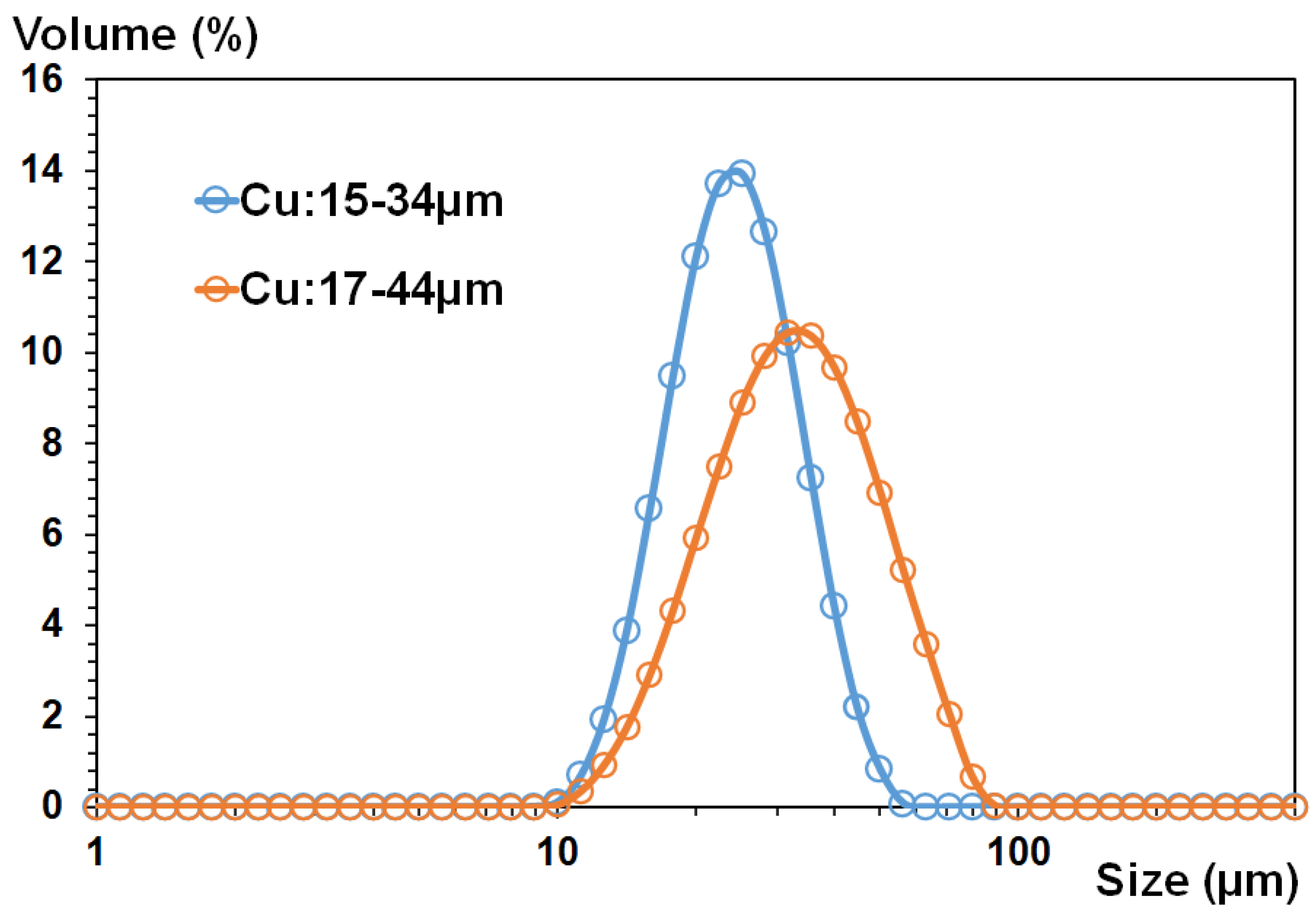
| Powder | Cu (17–44 µm) | Cu (15–33 µm) | Cu (17–42 µm) | ||||||
| DE | 67% | 30% | 53% | 83% | 87% | 88% | 90% | 91% | >50 |
| Thickness (µm) | - | - | 120 | 300 | 450 | 370 | 400 | 300 | - |
Publisher’s Note: MDPI stays neutral with regard to jurisdictional claims in published maps and institutional affiliations. |
© 2022 by the authors. Licensee MDPI, Basel, Switzerland. This article is an open access article distributed under the terms and conditions of the Creative Commons Attribution (CC BY) license (https://creativecommons.org/licenses/by/4.0/).
Share and Cite
Lalu Khoitara, L.; Raoelison, R.N.; Costil, S. 60% IACS Conductive Metal Coating on a Polymer Surface: Achievement of a Highly Efficient Additive Processing by Cold Spraying. Powders 2022, 1, 262-272. https://doi.org/10.3390/powders1040018
Lalu Khoitara L, Raoelison RN, Costil S. 60% IACS Conductive Metal Coating on a Polymer Surface: Achievement of a Highly Efficient Additive Processing by Cold Spraying. Powders. 2022; 1(4):262-272. https://doi.org/10.3390/powders1040018
Chicago/Turabian StyleLalu Khoitara, Libin, Rija Nirina Raoelison, and Sophie Costil. 2022. "60% IACS Conductive Metal Coating on a Polymer Surface: Achievement of a Highly Efficient Additive Processing by Cold Spraying" Powders 1, no. 4: 262-272. https://doi.org/10.3390/powders1040018