Article

Impact of Nanoparticles on Heat Transfer Enhancement and Thermal Performance Improvement in HTS Power Transformers

by
Mahdi Mahamed
and
Seyyedmeysam Seyyedbarzegar
*
Faculty of Electrical Engineering, Shahrood University of Technology, Shahrood 3619995161, Iran
*
Author to whom correspondence should be addressed.
Submission received: 23 September 2024 / Revised: 9 January 2025 / Accepted: 4 February 2025 / Published: 12 February 2025

Abstract

:
Despite the numerous benefits of high-temperature superconducting (HTS) power transformers, they are highly sensitive and vulnerable from a thermal perspective, particularly under fault current conditions due to their fault current tolerance properties. Ensuring the proper operation of the cooling system can enhance the transformer’s performance during fault and overload conditions. To improve the thermal management of this transformer in both convective heat transfer and nucleate boiling conditions, utilizing liquid nitrogen (LN2) nanofluid instead of conventional LN2 is a promising solution. In this study, a two-phase Eulerian model using ANSYS Fluent software is employed to analyze the impact of different volume fractions (VFs) of Al2O3 nanoparticles with a 40 nm diameter on the cooling performance of a power HTS transformer. The numerical simulations are conducted using the Ranz–Marshal method for heat transfer and the finite element method for solving the governing equations. Nanoparticle concentrations ranging from 0 to 1% are evaluated under various fault conditions. Additionally, the influence of nanoparticles on bubble behavior is examined, partially mitigating the blockage of cooler microchannels. The simulation reveals that adding nanoparticles to the fluid reduces the temperature of the hotspot by 29% in steady state and by 34–52% under different fault currents as a result of 0–46% enhancement of nucleate boiling heat transfer, thereby improving the cooling efficiency of the transformer.

1. Introduction

Transformers are essential components in power systems, as their continuous performance in distribution and transmission lines is crucial for minimizing transportation losses and adjusting voltage/current levels from generation to the distribution sector. Therefore, their reliable and uninterrupted operation is of utmost importance for ensuring continuous power delivery in any bulk power system [1,2,3].
High-temperature superconducting (HTS) technology is an attractive, promising, and beneficial technology for electrical applications such as transmission cables, fault current limiters, magnetic levitation, electrical machines, and transformers [4,5,6,7]. To transfer power on a large scale and at low voltage levels, superconducting transformers have been considered [8,9,10,11,12]. Due to their compact structure and permanent usage in the power grid, although the HTS transformer is a useful device compared to other HTS equipment [13,14,15,16,17], temperature can significantly affect its performance.
The thermal performance of HTS transformers is crucial in terms of total construction cost and thermal stability during operating conditions [18,19,20]. Thermal improvement of the HTS transformer involves two major aspects: reducing heat generation in heat sources and enhancing heat transfer between heat sources and coolant [21,22,23,24]. The heat produced in HTS cables includes AC loss (in steady state) and ohmic loss (in fault current conditions) [25,26,27,28,29,30]. Various approaches, such as using flux diverters or optimizing the structure of windings and tapes, have been explored to reduce AC loss [31,32,33,34,35,36,37,38].
Improving the heat transfer coefficient mainly depends on tape surface characteristics and the thermal properties of the cooling liquid. One effective solution is the use of nanoparticles in the cooling liquid to enhance convective heat transfer and the efficiency of the cooling system [39,40,41]. Previous research has investigated the effects of different nanoparticles such as Al2O3, TiO2, ZnO, and Fe2O3 on various base fluids, including water, oil, and liquid nitrogen (LN2) [42,43,44]. The results indicate that convective heat transfer is primarily influenced by the volume fraction, shape, and material of the nanoparticles [45].
Liquid nitrogen (LN2) is widely used in cryogenic cooling applications due to its excellent thermal properties and ability to maintain superconducting conditions. In HTS transformers, LN2 serves as an efficient coolant, enhancing both convective and nucleate boiling heat transfer processes. The low boiling point and high heat capacity of LN2 enable effective temperature regulation and thermal stability [46]. Incorporating nanoparticles into LN2 can further improve its thermal conductivity and heat transfer capabilities, making it a suitable choice for high-performance cooling systems in HTS applications.
Although nanoparticles improve convective heat transfer, their effect under fault conditions, characterized by short durations, has not been extensively investigated [27,29]. The main component of heat transfer in these conditions is nucleate boiling heat transfer [14,23]. The bubbles formed during the boiling process can obstruct the flow of LN2 within the microchannels, making it crucial to understand bubble behavior in nucleate boiling heat transfer.
Thermal analysis results indicate that the most sensitive parts of the HTS transformer under fault current conditions are the microchannels between two tapes of a disc [19]. Blockage of these thin channels by nitrogen bubbles during a fault can severely disrupt heat transfer, increasing the risk of tape damage [42]. Various solutions, such as using porous surfaces [14,23] or increasing fluid turbulence [22,24], have been proposed to address this issue by enhancing bubble dispersal. However, these solutions primarily affect bubble dispersal rates and not the radius, breakup frequency, or nucleate boiling heat transfer coefficient (NBHTC), which are critical factors in boiling heat transfer.
Numerous studies have examined the impact of nanoparticles on the heat transfer coefficient in boiling conditions, revealing both promising results and challenges. For instance, nanofluids can enhance the NBHTC by 77.7% at low nanoparticle volume fractions but reduce it by 30.3% at higher concentrations [47]. Non-spherical nanoparticles, particularly blade-shaped ones, significantly improve heat transfer compared to spherical nanoparticles [48]. Additionally, nanofluids have been shown to significantly increase critical heat flux, although nucleate boiling heat transfer coefficients remain similar to those of pure water [49]. The impact of sedimentation layers on the heat transfer coefficient has also been investigated, indicating that while nanofluids enhance heat transfer, sedimentation can reduce the heat transfer coefficient by 31% and critical heat flux by 16% [50]. Several other studies have explored the effect of nanoparticles on bubble behavior, including parameters like bubble diameter, generation frequency [51], bubble spacing [52], and molecular simulations of these impacts [53]. However, the effects of nanoparticles on nucleation site density, bubble generation frequency, waiting time, and breakup and coalescence frequencies remain underexplored.
The NP effect on physical properties of a bubble’s surface, such as in Figure 1, can create a significant impact on thermal behaviors of LN2. Building upon this literature, this paper focuses on investigating the impact of nanoparticles on the NBHTC in a practical model rather than the sample models examined in previous research. Furthermore, the study explores the effect of nanoparticles on bubble behavior in conjunction with their direct impact on nucleate boiling heat transfer. This approach helps identify various challenges and benefits, with one of the most significant issues being the potential blockage of HTS transformer microchannels by coalescing or overgrown bubbles. Additionally, the mechanism by which nanoparticles affect the NBHTC during very short periods (<100 ms) is also investigated.
In this paper, the influence of nanoparticles on LN2 heat transfer and HSPT under various operating conditions, including full load, overload, and fault conditions, is examined. Additionally, the impact of nanofluids on the convective heat transfer rate and the effect of enhanced convection heat transfer on cooling system performance is evaluated. Furthermore, the effect of the VF of nanoparticles on bubble formation inside the microchannels and NBHTC is investigated under fault current conditions with different amplitudes.

2. Governing Equations

In the thermal analysis, the influence of nanoparticles on the heat transfer performance of the HTS transformer was examined under both steady-state and transient conditions. In both of these modes, the first step is calculating the heat generated in the windings and other parts of the HTS transformer, and the second step is focused on analyzing the heat transfer rate. The flowchart shown in Figure 2 describes the process of this paper.

2.1. AC Loss Calculation

The AC loss of HTS tape includes hysteresis loss, which depends on the superconducting layer, eddy current loss, which mainly occurs in the stabilizer layer, and transporting loss. Equation (1) shows the AC loss of the coil with a unit of J/m/cycle [33,36,37]:
Q A C = 2 T / 2 T S E . J d S d t

2.2. Overload Losses

The overload condition in an HTS transformer is the flux flow mode in which electrical current is carried by the superconducting layer while the current is near critical current, making it more sensitive and fragile compared with the full load condition. The thermal stability of this mode is extremely important due to the relationship between critical current and temperature. Therefore, in order to operate the HTS transformer in this mode, the cooling system should be improved. By increasing heat transfer in this mode, the reliability of the transformer can be enhanced without entering fault current mode.
In fault current conditions, the resistance of the HTS tape suddenly increases due to the temperature of the tape exceeding its critical limit. The relationship between HTS layer resistance and the current in this mode can be calculated by Equation (2) [33,36,37]:
ρ t = E 0 J c J J c n 1
J c ( B ) = J c 0 1 + Z 2 B 2 + B 2 B 0 γ
where B0, Z, γ , and n are fitting parameters, where B0 = 0.137, Z = 0.001, γ = 2.2 , a n d   n = 25 .
Heat transfer in this mode depends on the thermal conductivity of the stabilizer and substrate layer, as well as the convective and evaporative heat transfer between LN2 and the tape surface.

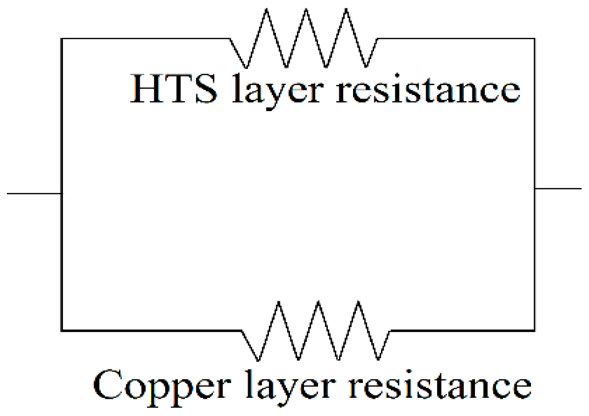
2.3. Fault Current Loss

In the fault condition, the ohmic loss is the dominant part of the loss, and AC loss can be ignored. Ohmic loss is mainly created in the superconducting layer and stabilizer layer. Due to the lower resistance of the copper layer compared to the superconducting layer, in fault current conditions, the majority of the heat in the HTS tape is generated in the stabilizers. Moreover, stabilizers are located on the top and bottom of the tape so that convective heat transfer occurs here. Therefore, analyzing these layers is important in fault current conditions. By neglecting the resistance of other layers (such as the substrate, buffer, and Ag), the electric circuit of the HTS tape used to calculate the ohmic loss in fault current is shown in Figure 3.
Equation (4) is used to calculate the ohmic loss of the tape in fault current conditions [33,36,37]:
Q F = ρ t l I 2 S
where ρ t = ρ t . H T S ρ t , c o p p e r , S is tape cross-area, and I is fault current.

2.4. Heat Transfer

Determining the temperature distribution in the winding of the HTS transformer is the primary objective of the thermal analysis, both in steady-state and transient conditions. In steady-state conditions, the hotspot temperature (HSPT) under overload conditions should not exceed the critical temperature. Conversely, under fault current conditions, the HSPT must remain below the quenching temperature of the tape. The energy conservation governing equation is applied in both numerical methods and finite element method (FEM) models to calculate the temperature distribution within the HTS winding. Equation (5) is employed in both steady-state and transient modes to determine the temperature distribution [19]:
V c d ρ c d C p c d T t = V c d . k c d T + P T Q T
where Q and P denote heat created inside the heat sources and heat transferred by heat sources surface, respectively.

2.4.1. Convection Heat Transfer

The convection heat transfer equation is shown in the following equation [22]:
P c o n v = h A T S T F
h = k l N u
The Nusselt number in Equation (7) represents the scale of the changing heat transfer coefficient, which will be examined in detail in the following sections.
Nanoparticles alter certain thermal properties of the liquid, ultimately modifying the Nusselt number equation. By introducing nanoparticles (NPs) into pure LN2, the properties of the LN2 nanofluid can be calculated using the following equations [54]:
ρ n f = 1 φ ρ b f + φ ρ n p
( ρ C p ) n f = 1 φ ( ρ C p ) b f + φ ( ρ C p ) n p
( ρ β ) n f = 1 φ ( ρ β ) b f + φ ( ρ β ) n p
μ n f = μ b f ( 1 φ ) 2.5
k n f = K n p + m 1 k b f ( m 1 ) ( k b f k n p ) φ K n p + m 1 k b f + ( k b f k n p ) φ k b f
ρ n f h f g , n f = 1 φ ρ b f h f g , b f + T b , b f T b , n p φ ρ n p h f g , n p
where m = 3/Ψ, in which Ψ is the particle sphericity.
Based on new properties of LN2 nanofluid, Rayleigh and Nusselt numbers are calculated by the following equations, respectively [55]:
R a = g ρ 2 C p β T l 3 α μ
N u = p l T α
The impact of nanoparticles on the Nusselt number is calculated by Equation (16) [56]:
N u = 2.14 R e 0.025 P r 0.33 φ 0.004 ( μ n f μ b f ) 0.192
P r = C p n f μ n f k n f

2.4.2. Nucleated Boiling Heat Transfer

Considering that the operating temperature of HTS transformers is slightly higher than the boiling point of LN2, the boiling of LN2 occurs in almost all fault currents. The Rohsenow correlation, shown in Equation (18), provides the best estimate for calculating the boiling heat transfer rate, with empirical validity for different NPs available in [57].
Rensselaer Polytechnic Institute’s (RPI) heat transfer model, used to calculate the heat transfer coefficient, involves convective, quenching, and evaporative heat transfer, as shown in Equations (19)–(21), respectively [58].
P n b = P c + P q + P e
P c = h ( T s T f ) ( A A b )
P q = 2 A b f d t w λ l ρ l C p l π ( T w T s )
P e = V b N W ρ v h f v
From these equations, a parameter changed by nanoparticles is nucleation site density, which is calculated by Equation (22) [59], and other parameters will be explained in the following section.
N W = 218.8 P r 1.63 1 γ Θ 0.4 Δ T w 3
P r = C p f μ f k f
γ = k s ρ s C p s k f ρ f C p f
where Θ is the porosity constant of the porous layer resulting from the deposition of NPs on the tape surface.

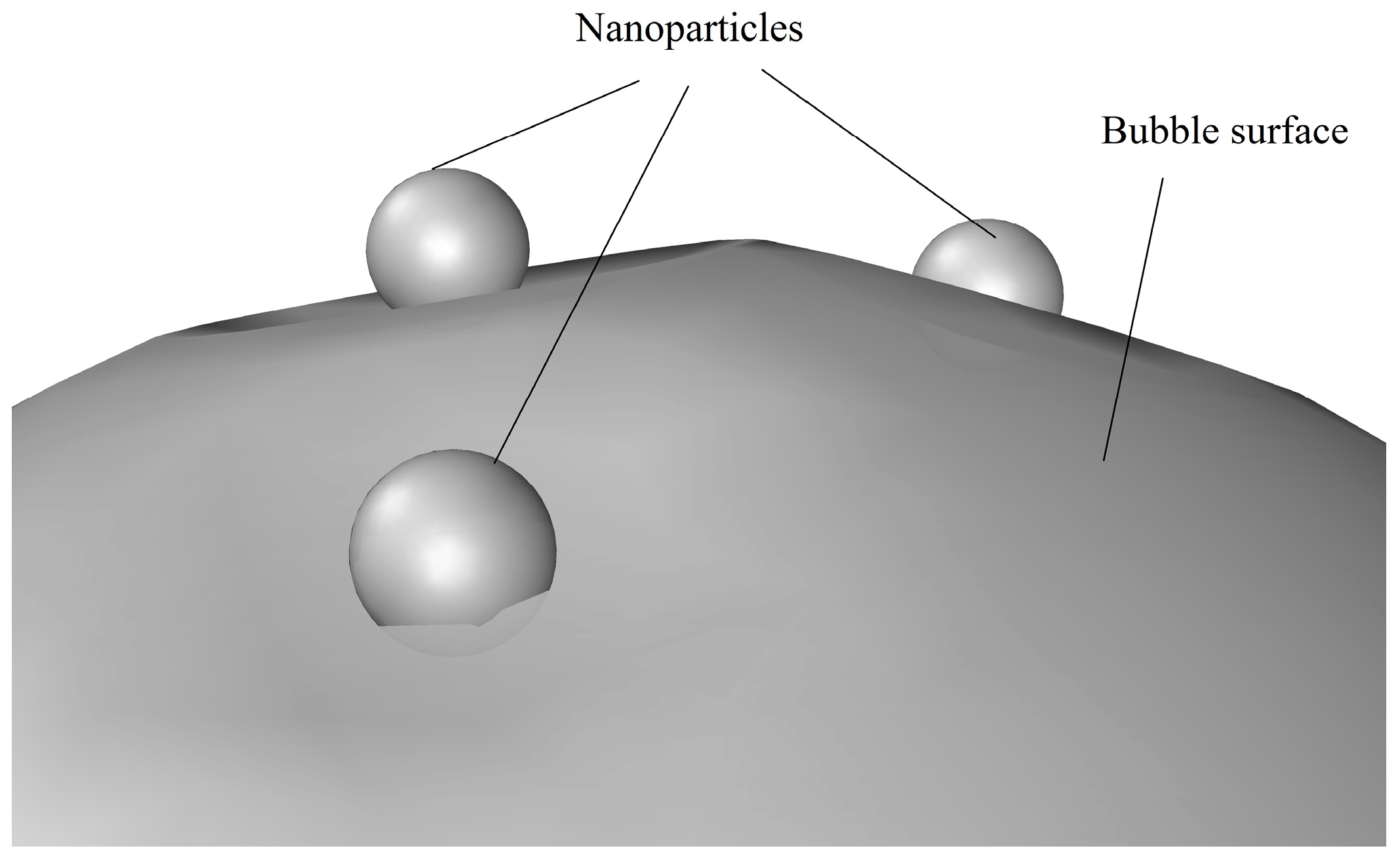
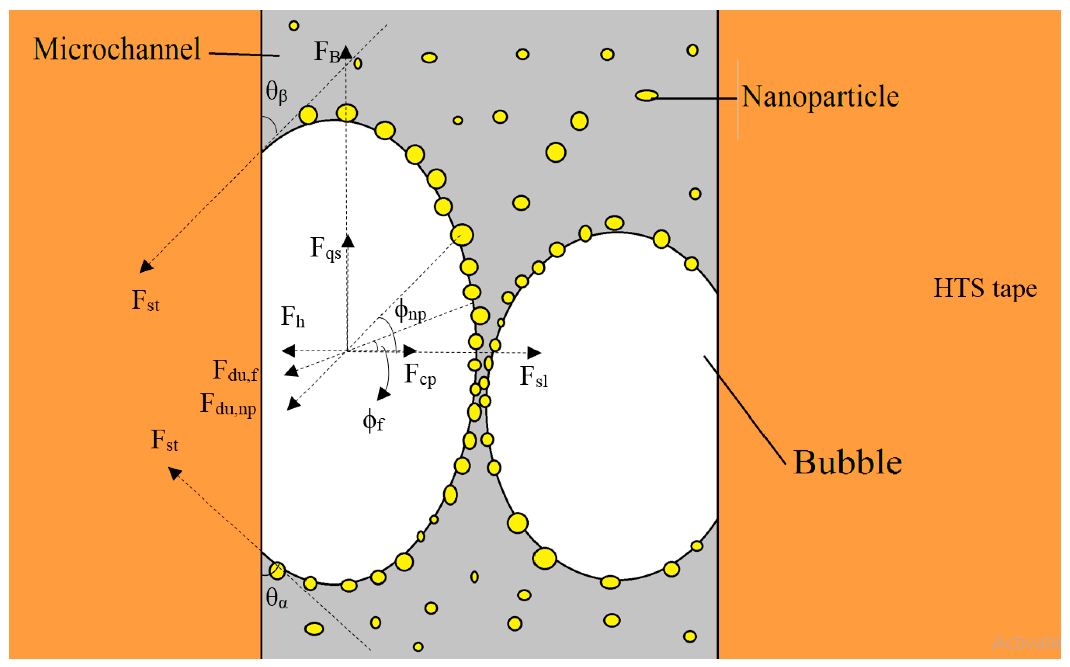
2.5. Bubbles Behaviors

Microchannels between two tapes of HTS winding play a crucial role in heat transfer, especially under fault current conditions. Figure 4a shows the schematic structure of the windings of the HTS transformer, and Figure 4b shows the geometry grid and the independent mesh of the model.
While bubbles significantly enhance the heat transfer coefficient, their coalescence can disrupt heat transfer in the microchannels. Bubble coalescence creates a blocked area inside the microchannels, which prevents other bubbles from being conveyed outside. The schematic of bubble creation and their coalescence is shown in Figure 5.
The movement of bubbles is influenced by horizontal and vertical forces, as shown in Figure 6, based on Equations (25) and (26):
F x = F s l + F h + F d u , f , x + F d u , n p , x + F s t , x + F c p
F y = F q s + F B + F d u , f , y + F d u , n p , y + F g + F s t , y
The calculation of each force component is shown in Equations (27)–(35) [60]:
F q s = 6 π ρ l µ U r 2 3 + 12 R e b + 0.75 1 + 3.315 R e b 0.5 1
F d u , x = ρ π R 2 R R ¨ + 3 2 R 2 s i n
F d u , y = ρ π R 2 R R ¨ + 3 2 R 2 c o s
F s t , x = 1.25 d B σ π θ α θ β π 2 θ α θ β 2 s i n θ α + s i n θ β
F s t , y = d B σ π ( θ α θ β ) c o s θ β c o s θ α
F B = 4 3 π r 3 ρ l ρ v g
F s l = 1 2 U 2 π ρ l R 2 Γ 0.5 1.146 ε R e b 0.5 2 + 3 4 Γ 0.5 2 0.5
F h = 9 8 ρ l Γ 2 π d W 2 4
F c p = π d W 2 4 2 σ 5 R
Based on the interaction between Ff and Fs, the stability of bubbles can be determined. The bubbles’ breakup and coalescence frequency are calculated by Equations (36) and (37), respectively [61].
f B = 0.25 8.2 ( ε d B ) 2 3 12 σ ρ L d B d B
f C = 5.77 α 2 ε 1 / 3 d B 11 / 3 e x p ( 1.29 ε 1 3 d B 5 6 ρ f σ )
where dB is the diameter of the bubbles calculated by the following equation [59]:
d B = 32 ( π 2 θ α θ β 2 ) π θ α θ β ( s i n θ α s i n θ β ) × ρ l V l 2 σ ( π 8 C D R e b 2 2 π ρ * 4 J a 4 P r 2 s i n φ )
ρ * = ρ n f ρ g ρ n f
Experimental results of the nanoparticle deposition effect on the tape surface show that NPs decrease the contact angle of the bubbles according to the Young–Laplace equation [62]:
c o s θ = γ s v γ s l σ r
where   γ s v γ s l is the adhesion tension, and r is the roughness factor of the nano-porous coating shown in Figure 7, both of which increase by adding NPs to the fluid [63].
Finally, one of the important properties of the liquids related to the NPs and effects on Equations (30), (35)–(38) is the surface tension of the liquid calculated by Equation (41) [64]:
σ = σ f + R g T Γ b Σ ( ω p + ω p K p φ + K Σ K p K Σ 1 + K p φ φ ω p + ω p K p K Σ 1 K p l n l n 1 + K p φ )
where ω p , K p , and K Σ are the number of adsorption sites for one nanoparticle, equilibrium adsorption constant, and ratio surface to bulk preference that is calculated by the following equations, respectively.
ω p = M p ρ f L f M f ρ p L p
K p = δ m L p π k B T Φ m e Φ m k B T
K Σ = Γ p , m a x Σ Γ b Σ
Γ b Σ = ρ p M p L p 2 L f
Γ p , m a x Σ = 0.9 L p ρ p M p
Other parameters that affect the quenching heat flow and bubble behaviors are the bubble generation frequency and bubble waiting time calculated by Equations (47) and (48) [59].
f d = 4 g ( ρ f ρ g ) 3 d w ρ f
t w = 0.8 f d

2.5.1. Void Fraction

The void fraction, defined as the ratio of the gas phase volume to the total volume in a two-phase flow, is crucial in microchannel heat transfer as it directly affects the NBHTC, pressure drop, and flow patterns [65]. During short periods, accurate prediction of void fraction is essential for optimizing thermal performance and ensuring efficient heat transfer. The addition of nanoparticles can significantly impact the void fraction by altering the fluid’s properties, such as thermal conductivity and viscosity, leading to enhanced heat transfer rates and potentially more stable flow patterns [66]. Moreover, the investigation of void fraction patterns can determine the blocked points and areas inside the microchannels. However, the exact effect depends on factors like nanoparticle concentration, size, and material, which can either promote or hinder bubble formation and growth [66,67]. Zuber and Findlay [68] were among the earliest investigators to introduce a general framework for the drift flux model to determine void fraction according to Equation (49):
α = X C X + ρ g ρ f ( 1 X ) + ρ g u g j G
where α is the void fraction, X is a universal parameter depending on heat flux, C is termed the distribution parameter, G is mass velocity, and ugj is drift velocity.
The impact of NPs on the Zuber equation is obtained by the addition of a function representing the effect of nanoparticles on the void fraction.

2.5.2. Governer Equations

The LN2 movement inside the cryostat is estimated by momentum, Navier–Stokes, and energy governing equations, which are shown in Equations (50)–(52), respectively, solving two adjacent meshes [22].
ρ l t + . ρ l v = 0
ρ l . v = P e + ρ g + μ 2 v
ρ l C p . T D P e D t = k 2 T + q w
where v is the fluid velocity, F is the body force vector, Pe is the pressure, and qw is volumetric heat source inside the transformer.

3. Results

The specifications of the 250 MVA HTS power transformer designed for OS application are detailed in Table 1 and Table 2 [14,23]. The physical and thermal properties of Al2O3 NPs are shown in Table 3. This paper utilizes Al2O3 nanoparticles of varying diameters and VFs to enhance the heat transfer coefficient. The findings are categorized into four sections: (1) steady-state analysis with AC loss as the heat source, (2) convective and evaporative heat transfer analysis under overload conditions, (3) nucleate boiling heat transfer analysis with fault current loss as the heat source, and (4) bubble behavior analysis under fault conditions.
The model includes two adjacent tapes within one of the double-pancake windings (HV winding) to illustrate the impact of nanoparticles on heat transfer within the microchannel between these tapes.

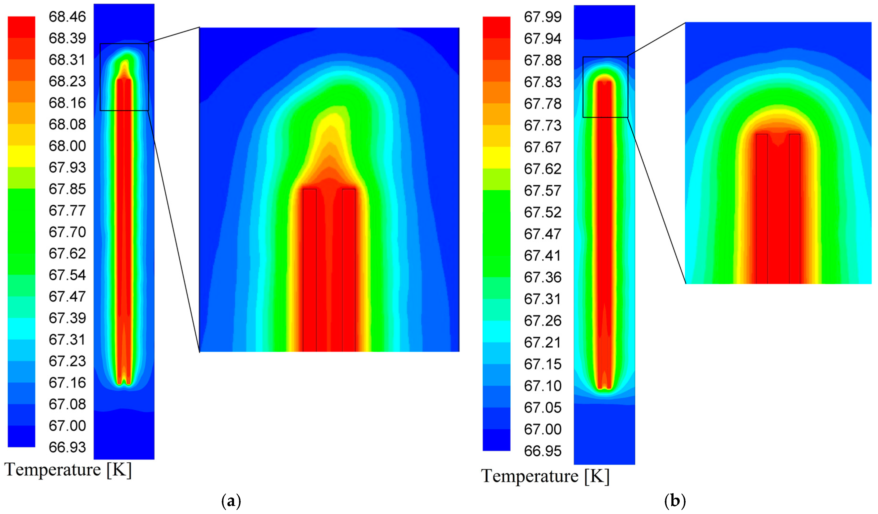
3.1. Steady-State Heat Transfer

Increasing the convective heat transfer coefficient in the steady state of the HTS transformer can optimize the operation of the cooling system of the HTS transformer in order to decrease the temperature of the tapes in the steady state. The heat sources of the tapes in this condition are limited to AC loss, as calculated by Equation (1). According to Equations (7) and (12), the convective heat transfer coefficient of a nanofluid primarily depends on the VF of nanoparticles. The convective heat transfer coefficient for Al2O3 nanoparticles with a 40 nm diameter is illustrated in Figure 8.
The temperature distribution on the tapes in a steady state is depicted in Figure 9. Comparing Figure 9a,b reveals that adding nanoparticles to LN2 decreases the natural flow of LN2. This flow is driven by the dependence of LN2 density on temperature and is directed opposite to gravity. This phenomenon can be explained using Equations (8) and (11).

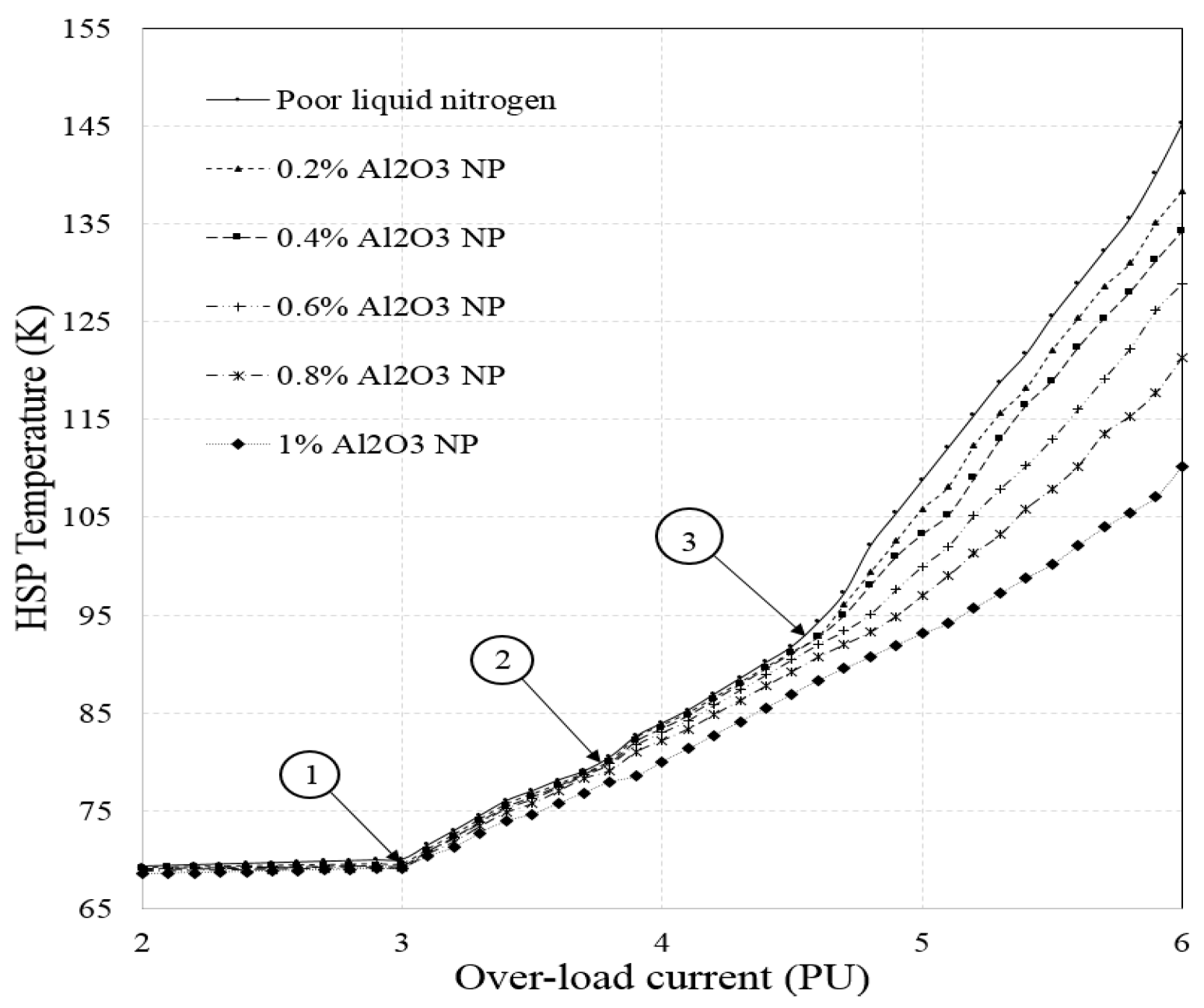
3.2. Overload Thermal Analysis

The flux flow state is a critical mode of HTS transformer operation. In this state, the current in the tapes is near the critical current. When the current exceeds the critical level, the resistance of the HTS layer increases significantly, causing most of the current to be carried by the superconducting layer until the temperature reaches the critical point, leading to quenching. While this state is not ideal for the continuous operation of the transformer, by enhancing the heat transfer coefficient in this mode, the transformer can be used under the overload condition for limited periods. Therefore, by enhancing heat transfer through the addition of nanoparticles in this mode, the HTS power transformer can withstand limited overloads for short periods, which can be further investigated based on future plans for offshore wind farms.
The hotspot temperature of the tapes for different currents is illustrated in Figure 10. In this figure, point (1) represents the critical current point of the YBCO tapes, point (2) indicates the saturated temperature of LN2, and point (3) denotes the critical temperature of YBCO.
In the region between point (a) and point (c), flux flow occurs, and the power transformer can tolerate a fairly long time in the region (a,b) and a very short time in the region (b,c). As the VF (VF) of nanoparticles increases, the hotspot temperature decreases. This decrease in hotspot temperature is more pronounced at higher currents, leading to a reduction of approximately 30% in most cases. It should be noted that the use of NPs with smaller VFs has less impact on reducing the hotspot temperature.
As shown in Figure 10, at points (b) and (c), the tape current increases by about 8% and 10%, respectively, as a result of adding 1% NPs to the liquid nitrogen.

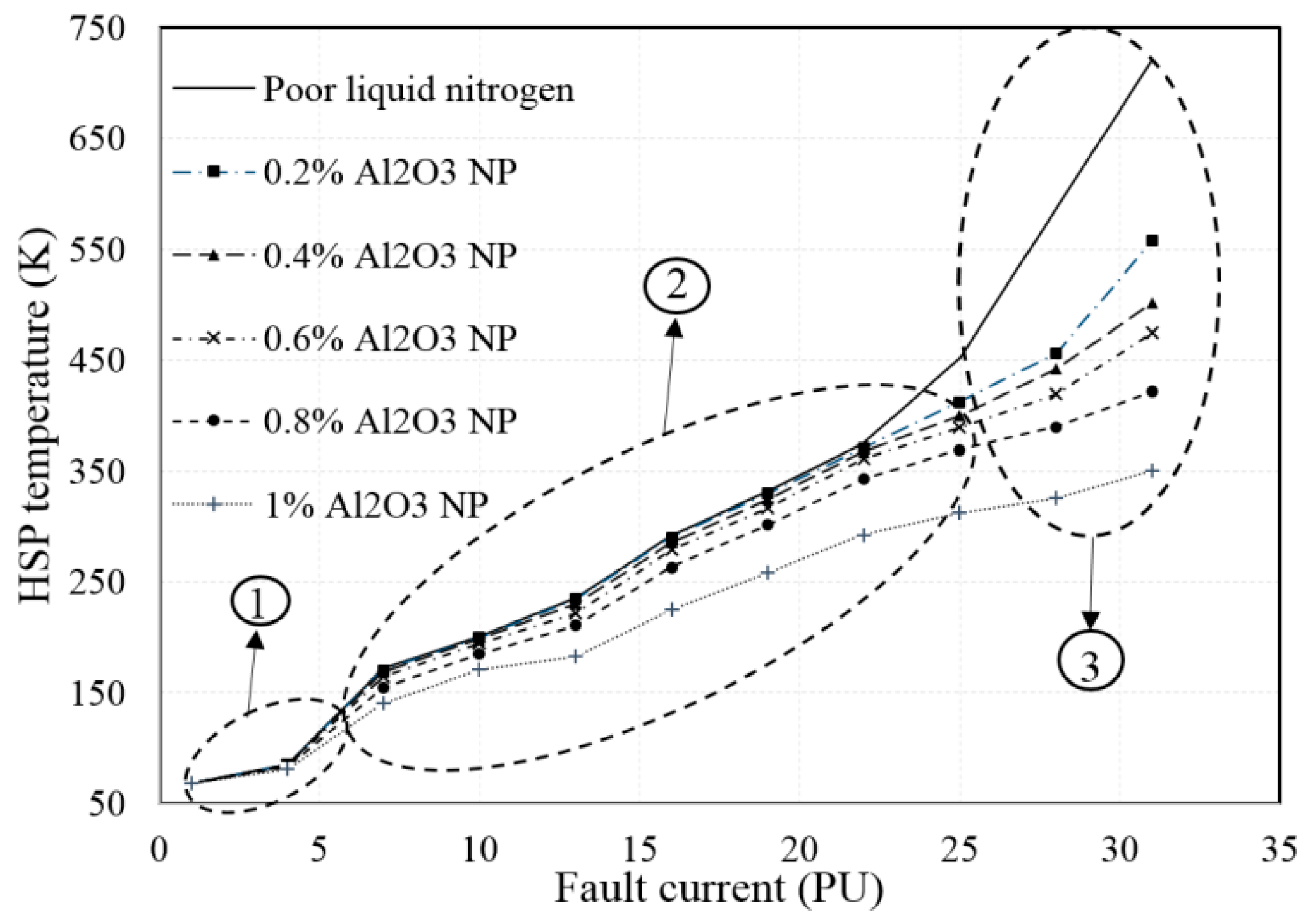
3.3. Fault Current Condition

3.3.1. Bubble Behavior Analysis

The coalescence of bubbles can create blocked areas inside the microchannels, disrupting the cooling performance of LN2. Bubble coalescence depends on several parameters, including bubble diameter, surface tension, and bubble break-up frequency, all of which change when NPs are added. These changes occur due to the forces that bring particles into the bubbles. Figure 11 shows the bubble density inside the microchannel with pure LN2 and LN2 containing 1% Al2O3 nanoparticles with a 40 nm diameter. As shown in this figure, the blocked points caused by large bubbles are completely removed in Figure 11b compared with Figure 11a. This results in a reduction in bubble size and bubble coalescence frequency. The effect of the reduction in the VF of bubbles on the temperature distribution is shown in the following section.

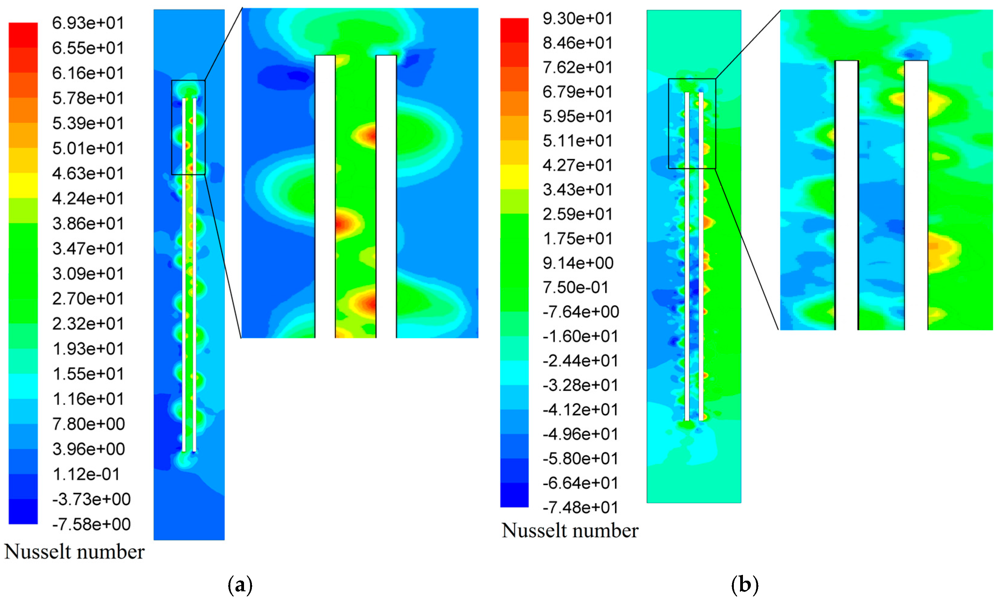
3.3.2. Fault Condition Heat Transfer

Heat transfer and cooling systems play a vital role in the fault current condition of the HTS transformer. The weak operation of the cooling system can cause serious damage to the HTS tape such as its burning and melting. In this condition, the main part of heat transfer is related to the bubbles generated by nucleate boiling.
Based on Equation (18), nucleate boiling heat transfer is related to the NPs’ diameters and VF. The impact of Al2O3 NPs’ VF on the HSPT of the HTS tapes at different fault currents is shown in Figure 12. In this figure, region 1 is the full load and overload operation, region 2 shows the quenching condition, and region 3 shows a state in which the cooling performance of the microchannel is disrupted. The HSPT of the tape in region (2) is decreased between 34 and 37% in different fault currents by adding 1% nanoparticles into the LN2. This factor of HSPT reduction is increased to 58% in region (3) as a result of changing the pool-boiling mode of heat transfer to the nucleated boiling mode. Figure 13 shows the temperature distribution on the tapes and surrounding liquid in 7 PU fault current and poor liquid nitrogen and 1% concentration nanofluid.
By increasing the bubble breakup rate and bubbles’ departure frequency, the quenching heat transfer is increased based on Equation (20). The results of Figure 13 show the increasing quenching heat transfer since the isotherms in Figure 13b are expanded compared with Figure 13a.
The Nusselt number distribution around the tape in pure LN2 and nanofluid LN2 is shown in Figure 14a,b, respectively. This comparison demonstrates the direct effect of adding nanoparticles on the heat transfer coefficient. The higher density scattering of the Nusselt number in Figure 14b compared to Figure 14a results from the increased density of nucleation sites, as described by Equation (22).

Comparison

Table 4 provides a comparison between the results of this paper and those of other similar studies. The comparison indicates that the increase in the heat transfer coefficient depends on various factors, such as the base fluid, NP concentration, NP shape and size, heat flux, and ambient conditions. However, the logical range of this increase is between 30% and 60%. This paper achieved a 52% improvement of the NBHTC. The results of this study are in the upper-average range of NBHTC improvements achieved by adding nanoparticles.

4. Conclusions

Due to the properties of superconducting materials, the heat transfer coefficient is more important compared with conventional transformers. Microchannels among the tapes of the HTS transformer coil have an important cooling performance during the fault current and overload condition. The blocking of these channels by bubbles created in the boiling process disrupts the heat transfer between tapes and fluid.
The results of this paper show several achievements, including the following:
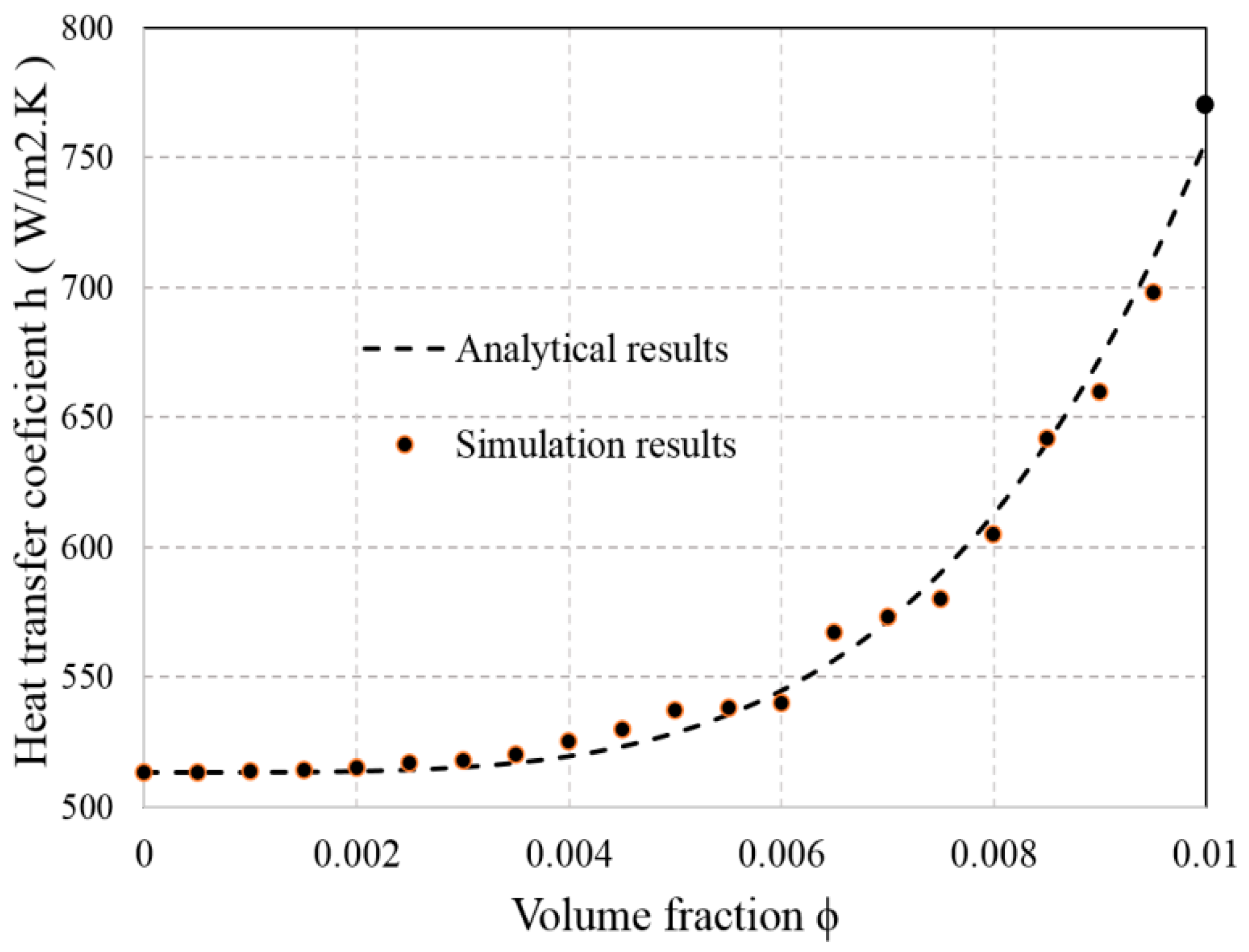
  • Adding nanoparticles to fluids increases the heat transfer coefficient both in convection and nucleated boiling mode.
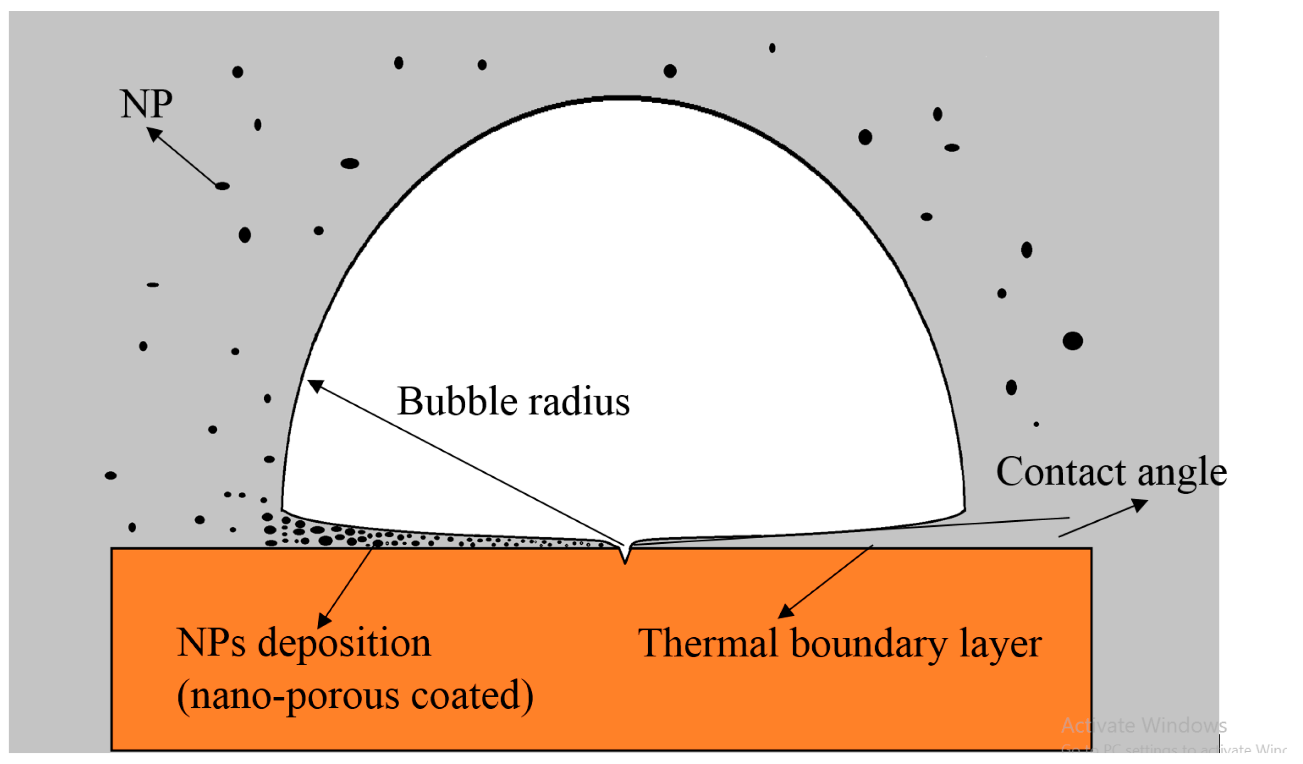
  • Nanoparticles can decrease the coalescence rate between the bubbles and reduce the bubbles’ size. These results improve the cooling performance of the cooling system described in this paper.
  • The results have shown that nanoparticles with a VF of 1% had the greatest effect on heat transfer and temperature distribution in microchannels.
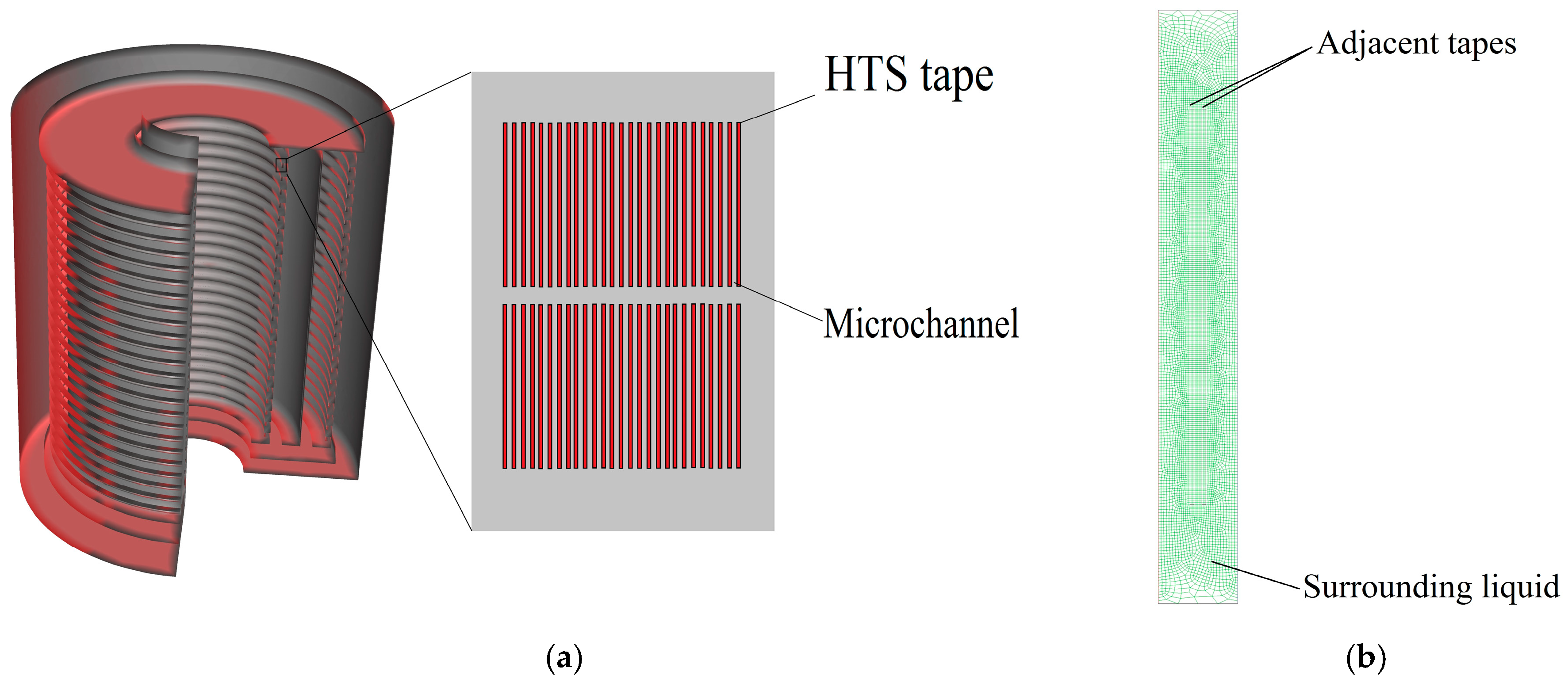
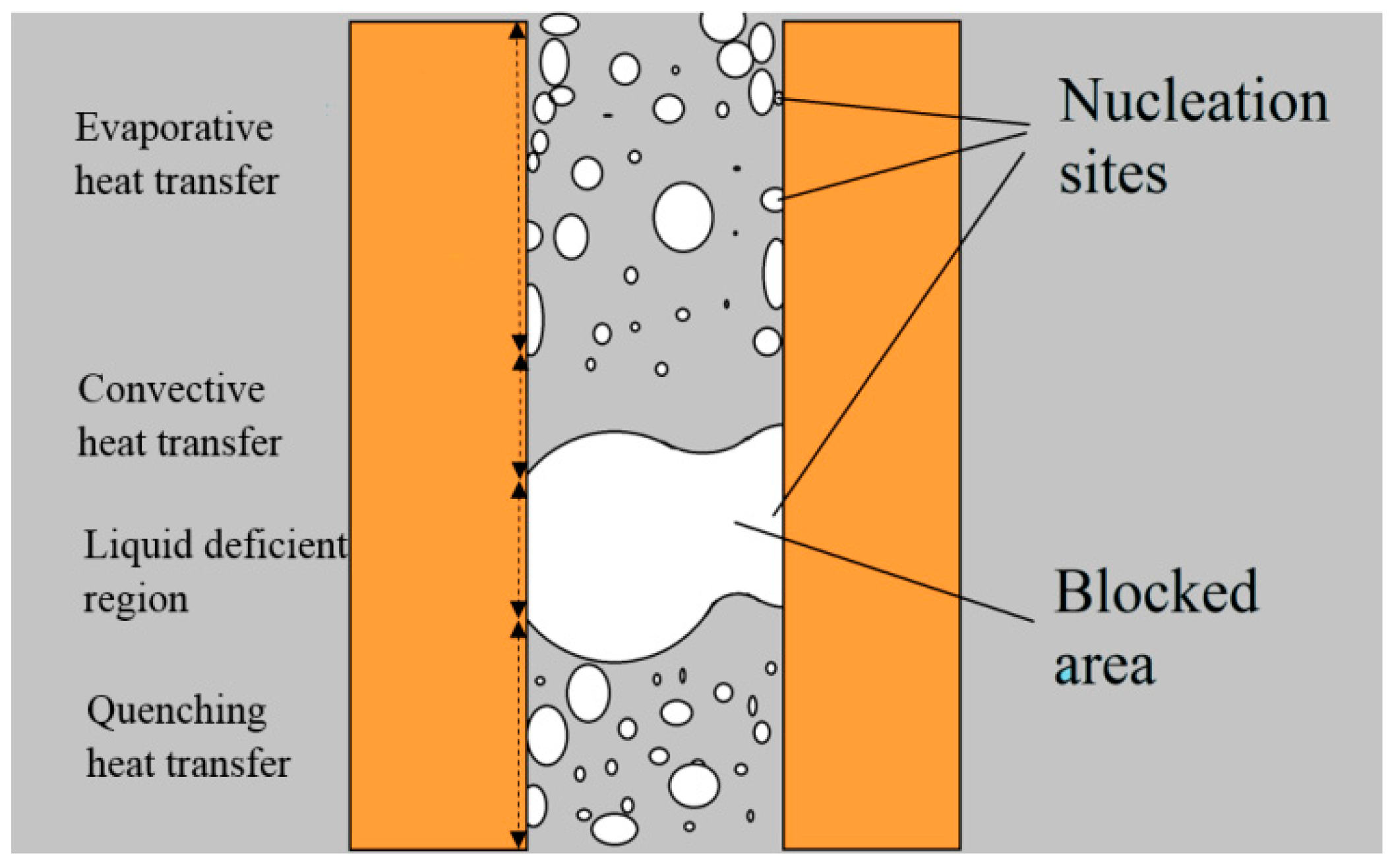
  • By adding nanoparticles, the blocked area inside the microchannels disappears. This result prevents the tapes from burning during the intense fault currents.
In summary, by adding Al2O3 NPs into the LN2 heat transfer coefficient, it is increased by about 60%, which decreases the HSPT of the tapes by 29%. The heat transfer coefficient is improved by adding NPs in fault conditions. In different fault current amplitudes, both increasing the NBHTC and opening blocked areas have a good effect on the HSPT reduction. In these conditions, the HSPT of tapes is decreased by about 34% in low fault currents (7 PU) and 54% in intense (32 PU) fault currents.

Author Contributions

M.M.: Conceptualization, Investigation, Software, Validation, Writing—original draft. S.S.: Conceptualization, Investigation, Methodology, Supervision, Validation, Writing—review & editing. All authors have read and agreed to the published version of the manuscript.

Funding

The authors declare that they have no known competing financial interests or personal relationships that could have appeared to influence the work reported in this paper.

Data Availability Statement

Data will be made available on request.

Conflicts of Interest

The authors declare no conflict of interest.

Nomenclatures

SymbolDescription (unit)
Q A C AC loss (W)
J Current density (A)
E Electrical field (V/m)
ρ t Electrical specific resistance (Ω)
E 0 Critical criterion of superconductor (V/m)
J c Critical current density (A)
J c 0 Self-field critical current (A)
B Parallel components of magnetic field (T)
B Perpendicular components of magnetic field (T)
Q F Fault current loss (W)
lTape length (m)
STape cross-section (m2)
V Volume (m3)
ρ Density (g/m3)
C p Specific heat capacity (J/kg.K)
k Thermal conductivity (W/m.K)
P Pressure (P)
hHeat transfer coefficient (W/m2.K)
T S Tape surface temperature (K)
T F Fluid temperature (K)
TbBoiling point temperature (K)
φ VF (%)
β Thermal expansion coefficient (1/K)
μ Dynamic viscosity (Ns/m2)
h f g Latent heat (J/kg)
R a Rayleigh number
NuNusselt number
ReReynolds number
PrPrandtl number
λ l Thermal diffusivity (m2/s)
A b Bubble contact area (m2)
A Tape surface are (m2)
N W Nucleation sites density (sites/m2)
F s l Shear lift force (N)
F h Hydrodynamic force (N)
F d u , f Bubble growth’s unsteady drag force from base fluid (N)
F d u , n p Bubble growth’s unsteady drag force from nanoparticles (N)
F s t Surface tension force (N)
F c p Contact force (N)
F q s Quasi-steady drag in the flow direction (N)
F g Gravity force (N)
F B Buoyancy force (N)
d B Bubble departure diameter (m)
ε Energy dissipation rate per mass (m2/s2)
RBubble radius (m)
фInclined angle (rad)
θ α Advancing contact angle (rad)
θ β Receding contact angle (rad)
σSurface tension (N/m)
Θ Nanoparticles porosity factor (%)
L p Characteristic length of nanoparticle (m)
L f Characteristic length of fluid (m)
δ m First minimum of potential well (m)
Φ m Total potential energy at first minimum (van der Waals potential energy)(J)
kBBoltzmann constant (J/K)
Γ p , m a x Σ Maximum surface concentration (mol/m2)
MMolar mass fluid molecule
IflFull load current amplitude
IcCritical current
VFn
VFmax
Volume fraction in step n
Maximum volume fraction considered
Subscript
cdconductor
nfnanofluid
npnanoparticle
nbnucleated boiling
bbubble
ssolid
ffluid
ggas
lliquid
vvapor
bfbase fluid

References

  1. Yazdani-Asrami, M.; Mirzaie, M.; Akmal, A.A.S. No-Load Loss Calculation of Distribution Transformers Supplied by Nonsinusoidal Voltage Using Three-Dimensional Finite Element Analysis. Energy 2013, 50, 205–219. [Google Scholar] [CrossRef]
  2. Yazdani-Asrami, M.; Mirzaie, M.; Akmal, A.S.; Gholamian, S.A. Life Estimation of Distribution Transformers Under Non-Linear Loads Using Calculated Loss by 2D-FEM. J. Elect. Syst. 2011, 7, 12–24. [Google Scholar]
  3. Yazdani-Asrami, M.; Mirzaie, M.; Akmal, A.A.S. Investigation on Impact of Current Harmonic Contents on the Distribution Transformer Losses and Remaining Life. In Proceedings of the 2010 IEEE International Conference on Power and Energy, Kuala Lumpur, Malaysia, 29 November–1 December 2010; pp. 689–694. [Google Scholar] [CrossRef]
  4. Sadeghi, A.; Barzegar, S.Μ.S.; Yazdani-Asrami, M. A Simple and Fast Computation Equivalent Circuit Model to Investigate the Effect of Tape Twisting on the AC Loss of HTS Cables. Eng. Technol. Appl. Sci. Res. 2022, 12, 8168–8174. [Google Scholar] [CrossRef]
  5. Song, W.; Pei, X.; Zeng, X.; Yazdani-Asrami, M.; Fang, X.; Fang, J.; Jiang, Z. AC Losses in Noninductive SFCL Solenoidal Coils Wound by Parallel Conductors. IEEE Trans. Appl. Supercond. 2020, 30, 5602509. [Google Scholar] [CrossRef]
  6. Sadeghi, A.; Seyyedbarzegar, S.; Yazdani-Asrami, M. Investigation on the Electrothermal Performance of a High-Temperature Superconducting Cable in an Offshore Wind Farm Integrated Power System: Fault and Islanding Conditions. IEEE Trans. Appl. Supercond. 2022, 32, 5401011. [Google Scholar] [CrossRef]
  7. Yazdani-Asrami, M.; Seyyedbarzegar, S.; Sadeghi, A.; de Sousa, W.T.; Kottonau, D. High Temperature Superconducting Cables and Their Performance Against Short Circuit Faults: Current Development, Challenges, Solutions, and Future Trends. Supercond. Sci. Technol. 2022, 35, 083002. [Google Scholar] [CrossRef]
  8. Sadeghi, A.; Bonab, S.A.; Song, W.; Yazdani-Asrami, M. Intelligent Estimation of Critical Current Degradation in HTS Tapes Under Repetitive Overcurrent Cycling for Cryo-Electric Transportation Applications. Mater. Today Phys. 2024, 42, 101365. [Google Scholar] [CrossRef]
  9. Yazdani-Asrami, M.; Song, W.; Morandi, A.; De Carne, G.; Murta-Pina, J.; Pronto, A.; Oliveira, R.; Grilli, F.; Pardo, E.; Parizh, M.; et al. Roadmap on Artificial Intelligence and Big Data Techniques for Superconductivity. Supercond. Sci. Technol. 2023, 36, 043501. [Google Scholar] [CrossRef]
  10. Sadeghi, A.; Song, W.; Yazdani-Asrami, M. Superconducting Transformers for Power, Energy, and Transportation Applications: An Introduction to Superconducting Technology for Transformer Engineers. Transform. Mag. 2024, 11, 98–110. [Google Scholar]
  11. Yazdani-Asrami, M.; Taghipour-Gorjikolaie, M.; Song, W.; Zhang, M.; Chakraborty, S.; Yuan, W. Artificial Intelligence for Superconducting Transformers. Transform. Mag. 2021, 8, 22–30. [Google Scholar]
  12. Yazdani-Asrami, M.; Sadeghi, A.; Song, W.; Madureira, A.; Murta-Pina, J.; Morandi, A.; Parizh, M. Artificial Intelligence Methods for Applied Superconductivity: Material, Design, Manufacturing, Testing, Operation, and Condition Monitoring. Supercond. Sci. Technol. 2022, 35, 123001. [Google Scholar] [CrossRef]
  13. Ghabeli, A.; Yazdani-Asrami, M.; Gholamian, S.A. A Novel Unsymmetrical Multi-Segment Concentric Winding Scheme for Electromagnetic Force and Leakage Flux Mitigation in HTS Power Transformers. IEEE Trans. Appl. Supercond. 2015, 25, 5500410. [Google Scholar] [CrossRef]
  14. Glasson, N.; Staines, M.; Buckley, R.; Pannu, M.; Kalsi, S. Development of a 1 MVA 3-Phase Superconducting Transformer Using YBCO Roebel Cable. IEEE Trans. Appl. Supercond. 2010, 21, 1393–1396. [Google Scholar] [CrossRef]
  15. Glasson, N.D.; Staines, M.P.; Jiang, Z.; Allpress, N.S. Verification Testing for a 1 MVA 3-Phase Demonstration Transformer Using 2G-HTS Roebel Cable. IEEE Trans. Appl. Supercond. 2012, 23, 5500206. [Google Scholar] [CrossRef]
  16. Glasson, N.; Staines, M.; Allpress, N.; Pannu, M.; Tanchon, J.; Pardo, E.; Badcock, R.; Buckley, R. Test Results and Conclusions From a 1 MVA Superconducting Transformer Featuring 2G HTS Roebel Cable. IEEE Trans. Appl. Supercond. 2016, 27, 5500205. [Google Scholar] [CrossRef]
  17. Staines, M.; Glasson, N.; Pannu, M.; Thakur, K.P.; Badcock, R.; Allpress, N.; D’souza, P.; Talantsev, E. The Development of a Roebel Cable Based 1 MVA HTS Transformer. Supercond. Sci. Technol. 2011, 25, 014002. [Google Scholar] [CrossRef]
  18. Yazdani-Asrami, M.; Gholamian, S.A.; Mirimani, S.M.; Adabi, J. Influence of Field-Dependent Critical Current on Harmonic AC Loss Analysis in HTS Coils for Superconducting Transformers Supplying Non-Linear Loads. Cryogenics 2021, 113, 103234. [Google Scholar] [CrossRef]
  19. Mahamed, M.; Seyyedbarzegar, S. Design and Thermal Analysis of a 250 MVA HTS Transformer for Substation of Offshore Wind Farms. Phys. C Supercond. Appl. 2024, 620, 1354503. [Google Scholar] [CrossRef]
  20. Yazdani-Asrami, M.; Staines, M.; Sidorov, G. Heat Transfer in HTS Transformer and Current Limiter Windings. In Proceedings of the 2nd International Workshop on Cooling Systems for HTS Applications (IWC-HTS), Karlsruhe, Germany, 13–15 September 2017. [Google Scholar]
  21. Staines, M.; Yazdani-Asrami, M.; Glasson, N.; Allpress, N.; Jolliffe, L.; Pardo, E. Cooling Systems for HTS Transformers: Impact of Cost, Overload, and Fault Current Performance Expectations. In Proceedings of the 2nd International Workshop on Cooling Systems for HTS Applications (IWC-HTS), Karlsruhe, Germany, 13–15 September 2017. [Google Scholar]
  22. Mahamed, M.; Seyyedbarzegar, S. Temperature Reduction of an HTS Transformer Under Short Circuit Fault by Modifying the Cryostat Structure: Impact of Perlator and Valve Location. Phys. C Supercond. Appl. 2024, 618, 1354429. [Google Scholar] [CrossRef]
  23. Yazdani-Asrami, M.; Staines, M.; Sidorov, G.; Eicher, A. Heat Transfer and Recovery Performance Enhancement of Metal and Superconducting Tapes Under High Current Pulses for Improving Fault Current-Limiting Behavior of HTS Transformers. Supercond. Sci. Technol. 2020, 33, 095014. [Google Scholar] [CrossRef]
  24. Mahamed, M.; Yazdani-Asrami, M.; Behjat, V.; Yazdani, A.; Sharifzadeh, M. Impact of Perlator on the Cooling Liquid Flow and Hottest Point Temperature of Superconducting Windings in HTS Transformer. Superconductivity 2022, 3, 100021. [Google Scholar] [CrossRef]
  25. Sadeghi, A.; Bonab, S.A.; Song, W.; Yazdani-Asrami, M. Short Circuit Analysis of a Fault-Tolerant Current-Limiting High Temperature Superconducting Transformer in a Power System in Presence of Distributed Generations. Superconductivity 2024, 9, 100085. [Google Scholar] [CrossRef]
  26. Song, W.; Jiang, Z.; Zhang, X.; Staines, M.; Badcock, R.A.; Fang, J.; Sogabe, Y.; Amemiya, N. AC Loss Simulation in a HTS 3-Phase 1 MVA Transformer Using H Formulation. Cryogenics 2018, 94, 14–21. [Google Scholar] [CrossRef]
  27. Yazdani-Asrami, M.; Staines, M.; Sidorov, G.; Davies, M.; Bailey, J.; Allpress, N.; Glasson, N.; Gholamian, S.A. Fault Current Limiting HTS Transformer with Extended Fault Withstand Time. Supercond. Sci. Technol. 2019, 32, 035006. [Google Scholar] [CrossRef]
  28. Jiang, Z.; Endo, N.; Wimbush, S.C.; Brooks, J.M.; Song, W.; Badcock, R.; Miyagi, D.; Tsuda, M. Exploiting Asymmetric Wire Critical Current for the Reduction of AC Loss in HTS Coil Windings. J. Phys. Commun. 2019, 3, 095017. [Google Scholar] [CrossRef]
  29. Pi, W.; Tian, B.; Wang, T.; Ma, Y.; Meng, Y.; Wang, Y.; Shi, Q.; Dong, J. Fault Current Characteristics of Parallel Stainless Steel & REBCO Tapes and a 6 kV/400 V HTS Transformer. IEEE Trans. Appl. Supercond. 2021, 31, 5500206. [Google Scholar] [CrossRef]
  30. Yazdani-Asrami, M.; Sadeghi, A.; Seyyedbarzegar, S.; Song, W. Role of Insulation Materials and Cryogenic Coolants on Fault Performance of MW-Scale Fault-Tolerant Current-Limiting Superconducting Transformers. IEEE Trans. Appl. Supercond. 2022, 33, 5500215. [Google Scholar] [CrossRef]
  31. Song, W.; Jiang, Z.; Yazdani-Asrami, M.; Staines, M.; Badcock, R.A.; Fang, J. Role of Flux Diverters in Reducing AC Loss in a Single-Phase 6.5 MVA HTS Traction Transformer for Chinese High-Speed Train Carrying High-Order Harmonic Currents. IEEE Access 2022, 10, 69650–69658. [Google Scholar] [CrossRef]
  32. Fang, X.; Wang, X.; Sun, Y.; Song, W.; Pei, X.; Jiang, Z.; Badcock, R.; Long, N.; Fang, J. Application of Flux Diverters in High Temperature Superconducting Transformer Windings for AC Loss Reduction. IEEE Trans. Appl. Supercond. 2021, 31, 5501005. [Google Scholar] [CrossRef]
  33. Yazdani-Asrami, M.; Song, W.; Zhang, M.; Yuan, W.; Pei, X. AC Transport Loss in Superconductors Carrying Harmonic Current With Different Phase Angles for Large-Scale Power Components. IEEE Trans. Appl. Supercond. 2020, 31, 5900205. [Google Scholar] [CrossRef]
  34. Ghabeli, A.; Yazdani-Asrami, M.; Besmi, M.; Gholamian, S.A. Optimization of Distributive Ratios of Apportioned Winding Configuration in HTS Power Transformers for Hysteresis Loss and Leakage Flux Reduction. J. Supercond. Nov. Magn. 2015, 28, 3463–3479. [Google Scholar] [CrossRef]
  35. Song, W.; Jiang, Z.; Staines, M.; Wimbush, S.C.; Badcock, R.; Fang, J. AC Loss Calculation on a 6.5 MVA/25 kV HTS Traction Transformer with Hybrid Winding Structure. IEEE Trans. Appl. Supercond. 2020, 30, 5500405. [Google Scholar] [CrossRef]
  36. Yazdani-Asrami, M.; Song, W.; Pei, X.; Zhang, M.; Yuan, W. AC Loss Characterization of HTS Pancake and Solenoid Coils Carrying Nonsinusoidal Currents. IEEE Trans. Appl. Supercond. 2020, 30, 5900709. [Google Scholar] [CrossRef]
  37. Jiang, Z.; Song, W.; Pei, X.; Fang, J.; Badcock, R.; Wimbush, S.C. 15% reduction in AC loss of a 3-phase 1 MVA HTS Transformer by Exploiting Asymmetric Conductor Critical Current. J. Phys. Commun. 2021, 5, 025003. [Google Scholar] [CrossRef]
  38. Yazdani-Asrami, M.; Taghipour-Gorjikolaie, M.; Song, W.; Zhang, M.; Yuan, W. Prediction of Nonsinusoidal AC Loss of Superconducting Tapes Using Artificial Intelligence-Based Models. IEEE Access 2020, 8, 207287–207297. [Google Scholar] [CrossRef]
  39. Bonab, S.A.; Yazdani-Asrami, M. Machine Learning-Based Model for the Intelligent Estimation of Critical Heat Flux in Nanofluids. Nano Express 2024, 5, 025012. [Google Scholar] [CrossRef]
  40. Uppada, V.R.; Dondapati, R.S. Role of Nanocryogenic Fluids in Optimizing the Thermohydraulic Characteristics of High Temperature Superconducting (HTS) Cables with Entropy Generation Minimization Strategy. Phys. C Supercond. Appl. 2020, 571, 1353620. [Google Scholar] [CrossRef]
  41. Yazdani-Asrami, M.; Sadeghi, A.; Atrey, M.D. Selecting a Cryogenic Cooling System for Superconducting Machines: General Considerations for Electric Machine Designers and Engineers. Int. J. Refrig. 2022, 140, 70–81. [Google Scholar] [CrossRef]
  42. Adnan Ashraf, W.; Khan, U.; Al-Johani, A.S.; Ahmed, N.; Mohyud-Din, S.T.; Khan, I.; Andualem, M. Impact of Freezing Temperature (Tfr) of Al2O3 and Molecular Diameter (H2O) d on Thermal Enhancement in Magnetized and Radiative Nanofluid with Mixed Convection. Sci. Rep. 2022, 12, 703. [Google Scholar]
  43. Lone, S.A.; Raizah, Z.; Saeed, A.; Bognár, G. Statistical Computation for Heat and Mass Transfers of Water-Based Nanofluids Containing Cu, Al2O3, and TiO2 Nanoparticles Over a Curved Surface. Sci. Rep. 2024, 14, 6908. [Google Scholar] [CrossRef]
  44. Noman, M.T.; Petru, M.; Amor, N.; Louda, P. Thermophysiological Comfort of Zinc Oxide Nanoparticles Coated Woven Fabrics. Sci. Rep. 2020, 10, 21080. [Google Scholar] [CrossRef]
  45. Ekiciler, R.; Çetinkaya, M.S.A.; Arslan, K. Heat Transfer Enhancement in An Equilateral Triangular Duct by Using an Al2o3/Water Nanofluid: Effect of Nanoparticle Shape and Volume Fraction. Heat Transf. Res. 2020, 51, 741–757. [Google Scholar] [CrossRef]
  46. Mahamed, M.; Seyyedbarzegar, S. Thermal Analysis of the HTS Transformer in the Fault Current Condition Considering the Tape Roughness Effect. Phys. C Supercond. Appl. 2024, 623, 1354548. [Google Scholar] [CrossRef]
  47. Qi, C.; Wan, Y.; Liang, L.; Rao, Z.; Li, Y. Numerical and Experimental Investigation Into the Effects of Nanoparticle Mass Fraction and Bubble Size on Boiling Heat Transfer of TiO2–Water Nanofluid. J. Heat Transf. 2016, 138, 081503. [Google Scholar] [CrossRef]
  48. Yahyaee, A. Influence of nanoparticle shapes in nanofluid film boiling on vertical cylinders: A numerical study. Int. J. Thermofluids 2024, 22, 100631. [Google Scholar] [CrossRef]
  49. You, S.M.; Kim, J.H.; Kim, K.H. Effect of Nanoparticles on Critical Heat Flux of Water in Pool Boiling Heat Transfer. Appl. Phys. Lett. 2003, 83, 3374–3376. [Google Scholar] [CrossRef]
  50. Mohebali, M.M.; Baniamerian, Z. Effect of Nanofluid Sedimentation on Heat Transfer and Critical Heat Flux in Boiling Flows. J. Therm. Anal. Calorim. 2024, 149, 8225–8244. [Google Scholar] [CrossRef]
  51. Jiang, Y.; Zhou, X.; Wang, Y. Effects of Nanoparticle Shapes on Heat and Mass Transfer of Nanofluid Thermocapillary Convection Around a Gas Bubble. Microgravity Sci. Technol. 2020, 32, 167–177. [Google Scholar] [CrossRef]
  52. Puli, U. Effect of AL2O3-Water Nano Fluid on Bubble Spacing in Subcooled Flow Boiling in a Horizontal Annulus. In Proceedings of the 10th International Conference on Heat Transfer, Fluid Mechanics and Thermodynamics, Orlando, FL, USA, 14–16 July 2014. [Google Scholar]
  53. Zhang, P.; Zhou, L.; Jin, L.; Zhao, H.; Du, X. Effect of Nanostructures on Rapid Boiling of Water Films: A Comparative Study by Molecular Dynamics Simulation. Appl. Phys. A 2019, 125, 142. [Google Scholar] [CrossRef]
  54. Li, S.; Yang, Q.; Ye, L.; Du, H.; Zhang, Z.; Huang, X.; Xu, J. Effect of Nano-Particle Concentration on Physical and Heat-Transfer Properties and Evaporation Characteristics of Graphite/N-Decane Nanofluid Fuels. ACS Omega 2022, 7, 3284–3292. [Google Scholar] [CrossRef]
  55. Mehrvarz, B.; Bahadori, F.; Moghaddam, S.Z. Heat Transfer Enhancement in Distribution Transformers Using TiO2 Nanoparticles. Adv. Powder Technol. 2018, 30, 221–226. [Google Scholar] [CrossRef]
  56. Moraveji, M.K.; Haddad, S.M.H.; Darabi, M. Modeling of Forced Convective Heat Transfer of a Non-Newtonian Nanofluid in the Horizontal Tube Under Constant Heat Flux with Computational Fluid Dynamics. Int. Commun. Heat Mass Transf. 2012, 39, 995–999. [Google Scholar] [CrossRef]
  57. Vontas, K.; Pavarani, M.; Miché, N.; Marengo, M.; Georgoulas, A. Validation of the Eulerian–Eulerian Two-Fluid Method and the RPI Wall Partitioning Model Predictions in OpenFOAM with Respect to the Flow Boiling Characteristics within Conventional Tubes and Micro-Channels. Energies 2023, 16, 4996. [Google Scholar] [CrossRef]
  58. Enjadat, S.M. CFD Comparison of Multiphase Models in the Pool Boiling State. Curved Layer. Struct. 2022, 9, 382–389. [Google Scholar] [CrossRef]
  59. Lee, C.Y.; Zhang, B.J.; Kim, K.J. Morphological Change of Plain and Nano-Porous Surfaces During Boiling and Its Effect on Nucleate Pool Boiling Heat Transfer. Exp. Therm. Fluid Sci. 2012, 40, 150–158. [Google Scholar] [CrossRef]
  60. Wu, W.; Chen, P.; Jones, B.G.; Newell, T. A Study on Bubble Detachment and the Impact of Heated Surface Structure in Subcooled Nucleate Boiling Flows. Nucl. Eng. Des. 2008, 238, 2693–2698. [Google Scholar] [CrossRef]
  61. Pistorius, P.C. Bubbles in Process Metallurgy. In Treatise on Process Metallurgy; Elsevier: Amsterdam, The Netherlands, 2014; pp. 179–196. [Google Scholar]
  62. Wenzel, R.N. Surface Roughness and Contact Angle. J. Phys. Chem. 1949, 53, 1466–1467. [Google Scholar] [CrossRef]
  63. Traciak, J.; Żyła, G. Effect of Nanoparticles Saturation on the Surface Tension of Nanofluids. J. Mol. Liq. 2022, 363, 119937. [Google Scholar] [CrossRef]
  64. Machrafi, H. Surface Tension of Nanoparticle Dispersions Unravelled by Size-Dependent Non-Occupied Sites Free Energy Versus Adsorption Kinetics. NPJ Microgravity 2022, 8, 47. [Google Scholar] [CrossRef]
  65. Mathure, N. Study of Flow Patterns and Void Fraction in Horizontal Two-Phase Flow; Oklahoma State University: Stillwater, OK, USA, 2010. [Google Scholar]
  66. Jabbarzadeh, A.; Halfina, B. Unravelling the Effects of Size, VF, and Shape of Nanoparticle Additives on Crystallization of Nanocomposite Polymers. Nanoscale Adv. 2019, 1, 4704–4721. [Google Scholar] [CrossRef]
  67. Elreafay, A.M.; Salem, K.M.; Abumandour, R.M.; Dawood, A.S.; Al Nuaimi, S. Effect of Particle Diameter and Void Fraction on Gas–Solid Two-Phase Flow: A Numerical Investigation Using the Eulerian–Eulerian Approach. Comput. Part. Mech. 2024, 1–23. [Google Scholar] [CrossRef]
  68. Zuber, N.; Findlay, J.A. Average Volumetric Concentration in Two-Phase Flow Systems. J. Heat Transf. 1965, 87, 453–468. [Google Scholar] [CrossRef]
  69. Wang, Y.; Deng, K.H.; Liu, B.; Wu, J.M.; Su, G.H. Experimental Study on ALN/H2O and Al2O3/H2O Nanofluid Flow Boiling Heat Transfer and Its Influence Factors in a Vertical Tube. In International Conference on Nuclear Engineering; American Society of Mechanical Engineers: New York, NY, USA, 2016; Volume 50039, p. V003T09A031. [Google Scholar]
  70. Wang, Y.; Deng, K.H.; Liu, B.; Wu, J.M.; Su, G.H. Experimental Study on Al2O3/H2O Nanofluid Flow Boiling Heat Transfer Under Different Pressures. In International Conference on Micro/Nanoscale Heat Transfer; American Society of Mechanical Engineers: New York, NY, USA, 2016; Volume 49651, p. V001T02A002. [Google Scholar]
  71. Wang, Y.; Deng, K.; Liu, B.; Wu, J.; Su, G. A Correlation of Nanofluid Flow Boiling Heat Transfer Based on the Experimental Results of ALN/H2O and Al2O3/H2O Nanofluid. Exp. Therm. Fluid Sci. 2017, 80, 376–383. [Google Scholar] [CrossRef]
  72. Choi, Y.J.; Kam, D.H.; Jeong, Y.H. Analysis of CHF Enhancement by Magnetite Nanoparticle Deposition in the Subcooled Flow Boiling Region. Int. J. Heat Mass Transf. 2017, 109, 1191–1199. [Google Scholar] [CrossRef]
  73. Sarafraz, M.M.; Arya, H.; Saeedi, M.; Ahmadi, D. Flow Boiling Heat Transfer to MgO-Therminol 66 Heat Transfer Fluid: Experimental Assessment and Correlation Development. Appl. Therm. Eng. 2018, 138, 552–562. [Google Scholar] [CrossRef]
  74. Balasubramanian, K.R.; Krishnan, R.A.; Suresh, S. Transient Flow Boiling Performance and Critical Heat Flux Evaluation of Al2O3-Water Nanofluid in Parallel Microchannels. J. Nanofluids 2018, 7, 1035–1044. [Google Scholar] [CrossRef]
Figure 1. Impact of nanoparticle on the bubble.
Cryo 01 00002 g001
Figure 2. General process of HTS transformer thermal analysis at different operation conditions considering nanoparticle effect.
Cryo 01 00002 g002
Figure 3. HTS tape electrical circuit on the quenching condition.
Cryo 01 00002 g003
Figure 4. (a) Three-dimensional schematic of the HTS winding and single double-pancake two-dimensional model; (b) study model and its meshing.
Cryo 01 00002 g004
Figure 5. Impact of NPs on bubble generation sites and their movement on the heat transfer mode between solid and liquid.
Cryo 01 00002 g005
Figure 6. Force vector effects on the bubbles.
Cryo 01 00002 g006
Figure 7. Impact of nanoparticles on the bubble shape at the departure time.
Cryo 01 00002 g007
Figure 8. Impact of Al2O3 nanoparticle VF on the HTC: comparison between analytical results and simulation results.
Cryo 01 00002 g008
Figure 9. Temperature distribution of HTS tapes in the full load operation: (a) poor LN2; (b) LN2 nanofluid with 1% AL2O3 nanoparticles.
Cryo 01 00002 g009
Figure 10. Impact of NPs’ VF on the HSPT of the tapes during different over-currents.
Cryo 01 00002 g010
Figure 11. VF of the bubbles inside the microchannel during the 7 PU fault current: (a) poor LN2; (b) nanofluid N2.
Cryo 01 00002 g011
Figure 12. Impact of NPs’ VF on the HSPT of the tapes during different fault currents.
Cryo 01 00002 g012
Figure 13. Comparison between temperature distribution on the tapes of (a) poor LN2 and (b) nanofluid LN2 by 1% VF of 40 nm Al2O3 particles.
Cryo 01 00002 g013
Figure 14. Comparison between Nusselt number distribution around the tapes of (a) poor LN2 and (b) nanofluid LN2 by 1% VF of 40 nm Al2O3 particles.
Cryo 01 00002 g014
Table 1. Transformer and its HTS tapes specifications.
ParameterValue
Capacity250 MVA
HV/LV voltage220/33 kV
HV/LV current655/4182.5 A
Tape materialYBCO
Tape dimension0.12 × 10 mm2
Critical current300 A (65 K)
200 A (77 K)
Microchannel width0.1 mm
Table 2. Dimensions and physical properties of transformer.
ElementDimensionMaterial
HV winding10 × 2500 mm40% Cupper, 50% Hastelloy, 4% silver, 1% YBCO, 5% other materials
LV winding2 × 5 × 2600 mm40% Cupper, 50% Hastelloy, 4% silver, 1% YBCO, 5% other materials
Cryostat1100 × 3000 mmGFRP with vacuum layer
Windings holders150 × 2600 mmGFRP
Core7500 × 4000 mmlaminated silicon steel
Table 3. Al2O3 nanoparticle specifications.
ParameterValue
Density2719 kg/m3
Specific heat843 (in 300 k)
Thermal conductivity0.045 W/m−k
Viscosity1.72 × 10−5 kg/m−s
Molecular weight26.98 kg/kmol
Particle size<100 nm
Table 4. Comparison of results relevant to boiling heat transfer increase by adding NPs to cooling fluids.
PaperImpact of Nanoparticle Conditions on Heat Transfer Coefficient Change (%)
Qi et al. [58]Improved up to 77.7% in low concentrations and decreased 30.3% in high concentrations
You et al. [60]Increased up to 200%
Mohebali et al. [61]Reduced to 31% due to the sedimentation
Wang et al. [69]Improved about 64%, 61% compared to water for AlN and c-Al2O3, respectively
Wang et al. [70]Enhanced about 86% using nanofluid compared to water
Wang et al. [71]Improved about 64%, 61% compared to water for AlN and c-Al2O3, respectively
Choi et al. [72]Enhanced up to 40% for nanofluid compared to water
Sarafraz et al. [73]Increased about 23.7% for 0.1 mass%
Balasubramanian et al. [74]Enhanced during the transient state/improved up to 15% for moderate volume concentration
Our studyImproved up to 52% for various NP concentrations
Disclaimer/Publisher’s Note: The statements, opinions and data contained in all publications are solely those of the individual author(s) and contributor(s) and not of MDPI and/or the editor(s). MDPI and/or the editor(s) disclaim responsibility for any injury to people or property resulting from any ideas, methods, instructions or products referred to in the content.

