Article

A Comparison of the Ballistic Performances of Various Microstructures in MIL-A-12560 Armor Steel

Department of Metallurgical and Materials Engineering, Atılım University, Ankara 06830, Turkey
Metals 2020, 10(4), 446; https://doi.org/10.3390/met10040446
Submission received: 8 March 2020 / Revised: 25 March 2020 / Accepted: 25 March 2020 / Published: 28 March 2020

Abstract

:
Due to their advantageous properties, there is a growing interest in developing armor steels containing fully or partially bainitic microstructures. In this study, bainitic and martensitic microstructures were obtained in rolled homogeneous armor (RHA) steel samples and their ballistic protection performances were investigated. RHA (MIL-A-12560) steel samples were subjected to isothermal heat treatments at three different temperatures, where one temperature (360 °C) was above the martensite formation start (Ms) temperature of 336 °C while the other two (320 °C and 270 °C) were below. For the assessment of the ballistic protection performance, the kinetic energy losses of the 12.7 mm bullets fired at the test samples were determined. The promising nature of the bainite microstructure was confirmed as the sample isothermally treated at 360 °C provided approximately 10% higher ballistic protection as compared to the regular RHA sample of tempered martensite microstructure. However, the ballistic performances of the isothermally treated samples decreased as the treatment temperature went below the Ms temperature. Following the ballistic tests, hardness measurements, impact tests at −40 °C, and macro- and microstructural examinations of the samples were performed. No correlation was found between the hardness and impact energies of the samples and their ballistic performances.

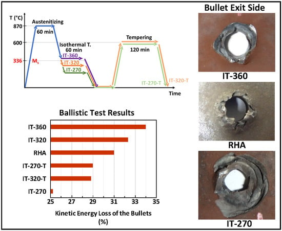
Graphical Abstract

1. Introduction

Although there are many ballistic protection applications in which non-ferrous or even non-metallic armors are being used, there are still some applications, such as heavy armored vehicles, where steel is the main material of choice due to its advantageous combination of properties like ballistic performance, lower cost, weldability, etc. The ballistic performance of a steel is essentially dependent on its mechanical behavior under the very high rate of loading experienced at ballistic speeds [1,2]. Unfortunately, studying such behavior experimentally in a laboratory is very difficult. Hence, the hardness and impact test results, although they are determined under very static conditions as compared to the ballistic speeds, remain as the conventional and practical indicators of ballistic performance. Therefore, in addition to some ballistic performance requirements, armor steel standards such as MIL-A-12560 also specify certain hardness and impact energy values [3,4,5]. Rolled homogeneous armor (RHA), which is one of the most widely used general purpose structural armor steels, meets these requirements through a tempered martensite microstructure obtained by the conventional quenching and tempering processes.
Naturally, most of the studies on the ballistic protection behavior of steels investigated martensitic microstructures of various alloy compositions tempered under different conditions. These studies show that, although a harder and tougher steel is expected to provide higher ballistic protection, the relation is not linear and is rather complex [6,7,8,9]. For example, it was suggested that strain hardening behavior is more determining than the absolute value of strength in certain situations [6].
In addition to martensite, bainite is also one of the most investigated microstructures in steels. Basically, it is the product of full or partial decomposition of austenite at temperatures that are sufficiently lower than the ones at which pearlite would form and higher than the ones where martensite would form. In classical physical metallurgy textbooks, bainite is conventionally grouped into two, as upper and lower types, where both are mixtures of ferrite and cementite but in different morphologies [10,11,12]. Most of the studies on bainitic microstructures have focused on the lower bainite, as this structure promises a higher combination of hardness and toughness values [13,14]. Meanwhile, mixed microstructures containing both bainite and martensite in various proportions have been reported to have advantageous properties as compared to a single structure [15,16,17]. Barranco et al. produced samples with martensite–bainite mixed microstructures in ASTM A723 steel and they found that martensite–25% bainite and martensite–66% bainite samples had higher impact energies than all martensite or all bainite structures at −40 °C for similar strength levels [15]. Similarly, Tomita observed significantly higher strength and impact energies with 25% bainite containing 0.4%C–Cr–Mo steel samples [16].
In addition to the upper and lower types, bainite can also take on another form known as carbide-free bainite, which consists of ferrite and carbon-enriched austenite [17]. This form of bainite is obtained in the presence of a sufficient amount of silicon (typically 1.4 wt.% or higher) or a few certain other elements in solution where the formation of cementite is prevented or retarded [18,19,20]. Nanostructured carbide-free bainitic steels developed by Bhadesia and his team have a remarkable combination of high hardness and high toughness values [21]. These bainitic steels with their specifically designed compositions are now offered as armor steels due to their much higher ballistic protection performance as compared to the regular armor steels with tempered martensite microstructures [22,23].
As explained above, there is a growing interest in developing new armor steels with carbide-free bainite microstructures [23,24,25]. Besides these special bainitic steels, it is also of interest to see if the ballistic protection performance of regular armor steels, which are produced to be used in a tempered martensite microstructure, can be increased through conventional bainite microstructures. A search through the open literature did not bring any relevant results, indicating that this question has not yet been answered. Therefore, the objective of this work was to create bainite and bainite–martensite mixed microstructures in RHA (MIL-A-12560) steel samples and to find out how these structures would compare with the regular RHA in terms of ballistic protection.

2. Materials and Methods

For this study, 200 × 200 × 12.7 mm3 samples cut from a large single plate of RHA steel produced by Arcelor-Mittal (Charleroi, Belgium) were used. The chemical composition of the RHA plate as measured by a Spectromaxx optical emission spectrometer (Spectro Analytical Instruments, Kleve, Germany) is given in Table 1. Basically, it is a Ni–Cr–Mo alloyed steel with a carbon content of 0.27 wt.%. The as-received RHA plate had a tempered martensite microstructure, as seen in Figure 1.
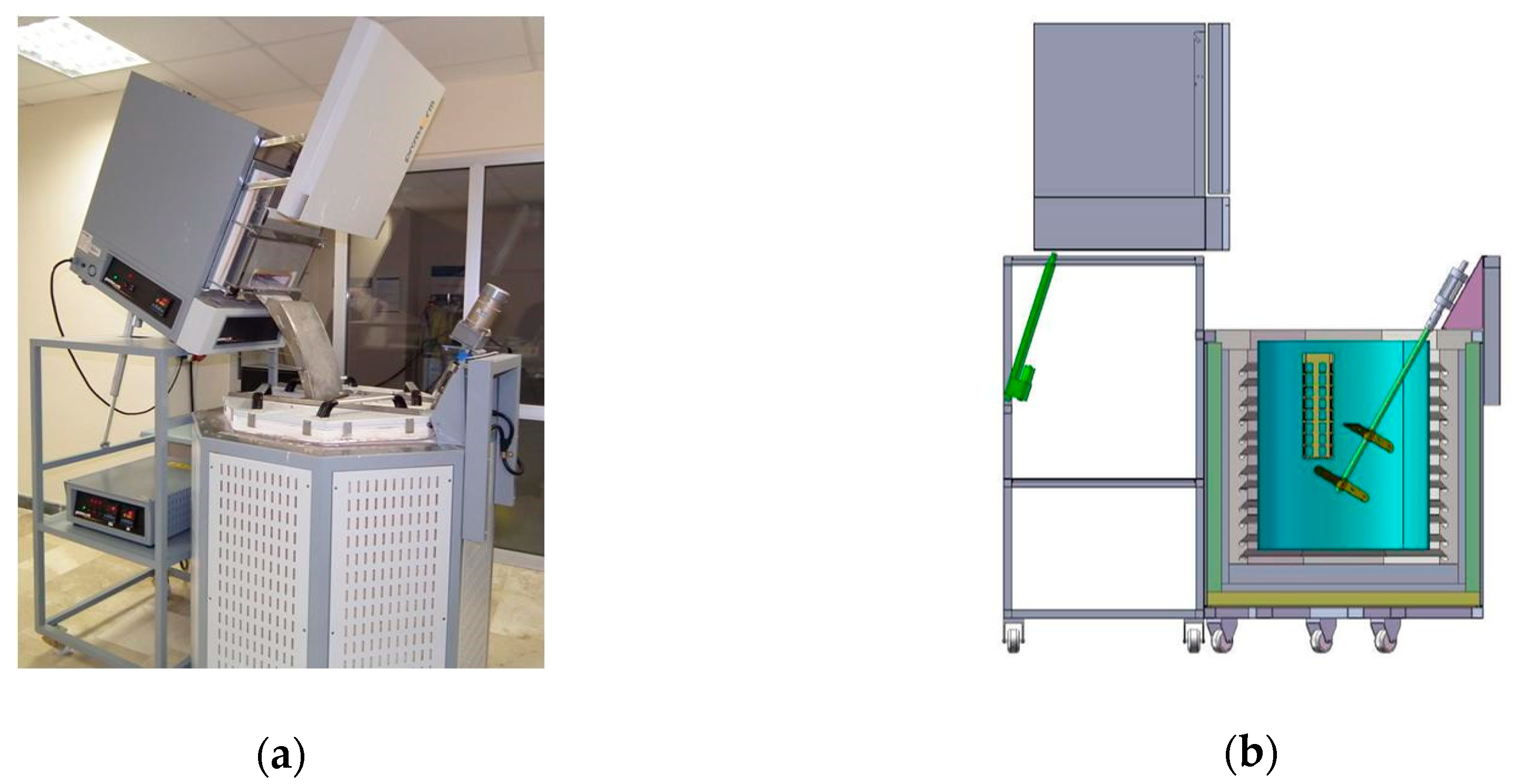
Isothermal heat treatment experiments were done using a custom-made heat treatment setup shown in Figure 2a. This setup consisted of an austenitization furnace and a 200-liter capacity salt bath containing Petrofer AS 135 (NaNO2–KNO3 mixture) heat treatment salt. The salt bath was continuously stirred during operation using a motorized mixer that ensured both efficient heat removal from the sample at the time of quenching and a uniform temperature distribution in the bath during the isothermal treatment (Figure 2b).
The heat treatment conditions applied to the RHA samples are summarized in Table 2 and graphically shown in Figure 3. Before the isothermal treatments, samples were normalized by austenitizing at 870 °C for 60 min followed by air cooling. Using the empirical formulas available in the literature [26,27,28,29,30,31], the martensite formation start (Ms) temperature for the chemical composition given in Table 1 was calculated approximately as 336 ± 12 °C.
By employing isothermal treatments at three different temperatures, where one temperature (360 °C) was above the Ms of 336 °C and the other two (270 °C and 320 °C) were below the Ms, the aim was to obtain one fully bainite and two bainite–martensite mixed microstructures with varying proportions, respectively. For the sub Ms treatment temperatures of 270 °C and 320 °C, two additional samples were also prepared where isothermal treatment was followed by tempering at 600 °C for 120 min.
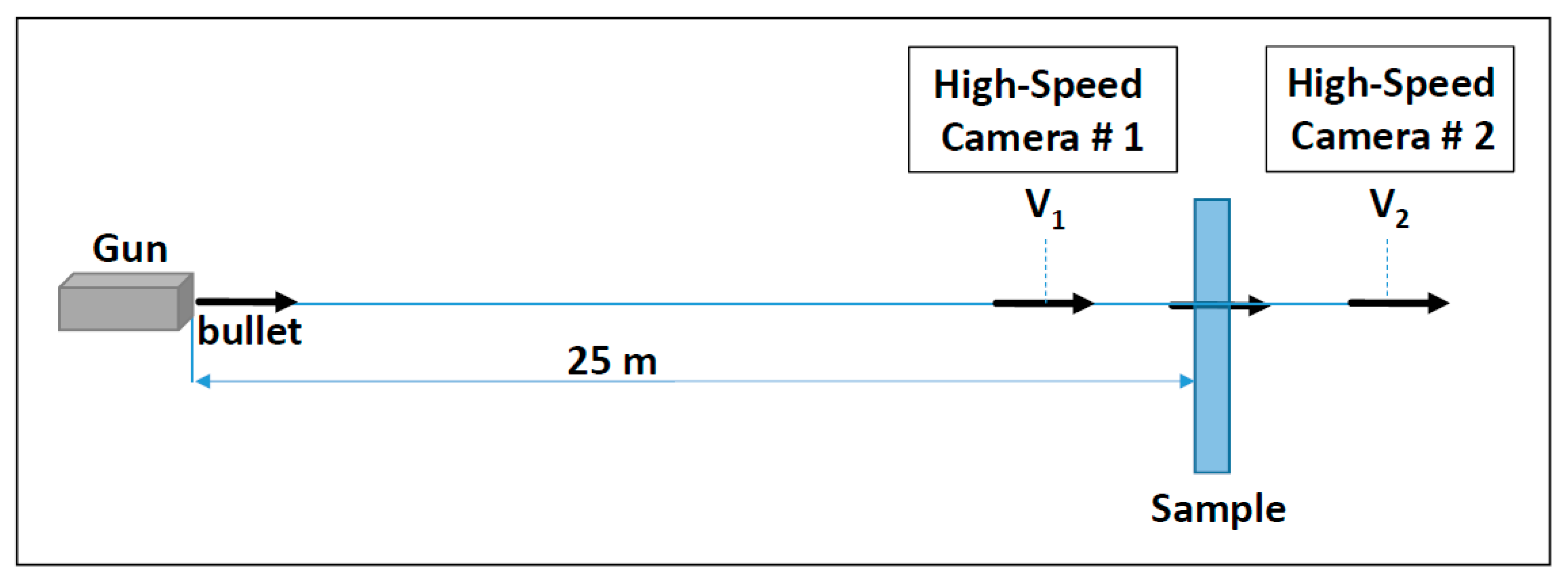
Ballistic tests were performed at the Ballistic Protection Center located on the Roketsan premises in Elmadag, Ankara, Turkey. Fully charged 12.7 mm bullets were fired from a distance of 25 m normal to the ballistic test samples. At least two shots were fired at each sample and the speed of the bullets before (V1) and after (V2) the hit were determined using a high-speed camera system (Figure 4).
The average bullet speed before the impact was 902 ± 9 m/s. Percent kinetic energy losses of the bullets (Equation (1)) were used as an indicator of the ballistic protection performance of the samples:
%   Loss   in   Kinetic   Energy = ( 100 ) ( V 2 2 V 1 2 V 1 2 )
An untreated (as-received RHA) sample was also tested under the same conditions in order to better assess the relative performances of the heat-treated samples.
After the ballistic tests, three standard v-notched Charpy impact test specimens (10 × 10 × 55 mm3 in size) were prepared from each ballistic test sample parallel to the rolling direction in compliance with the ASTM E23 standard. Impact tests were performed at −40 °C using an Instron SI pendulum impact testing machine (Instron, Norwood, MA, USA). Brinell hardness measurements (HBW 2.5/187.5) were taken using an EMCO M4U 025 G3 universal hardness testing machine (EMCO-TEST GMBH, Kuchl, Austria) and the average of five measurements was reported for each sample.
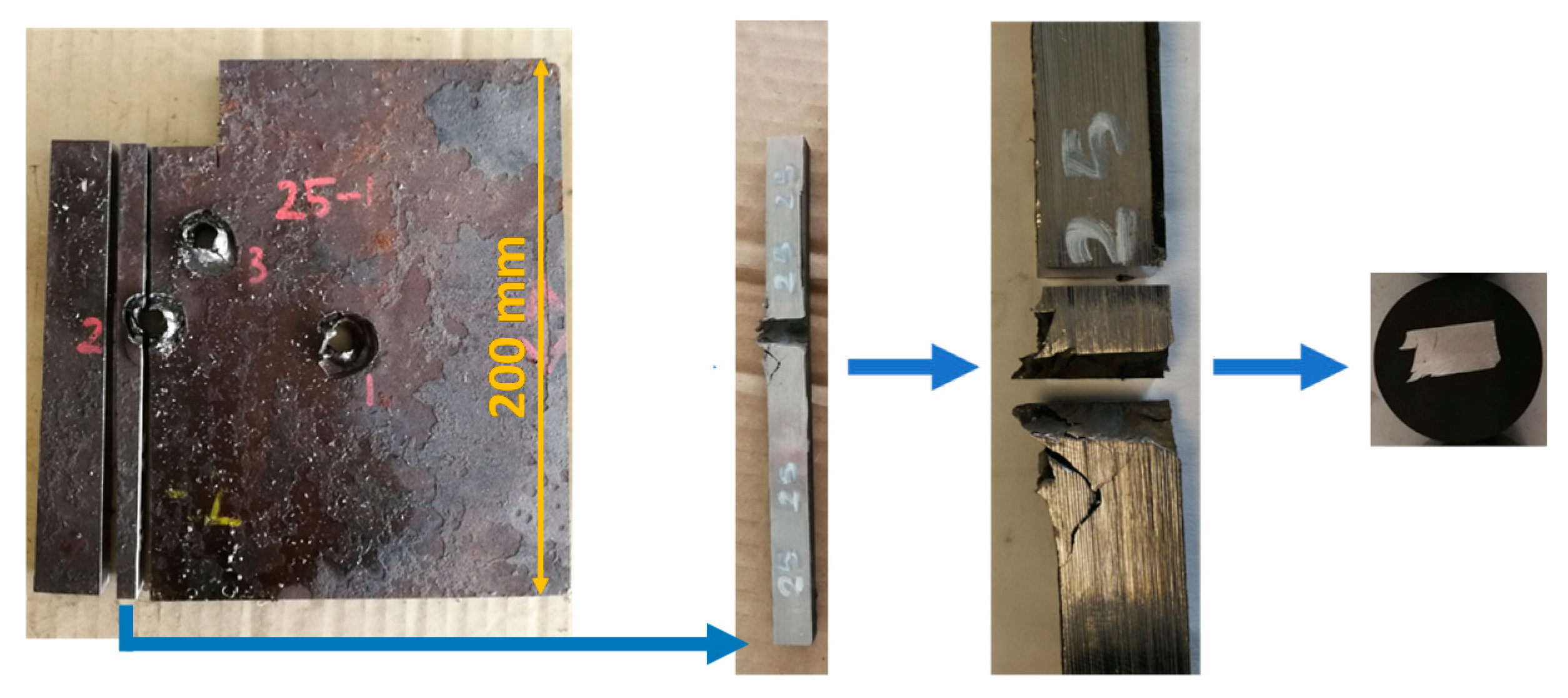
In order to examine the bullet holes created on the ballistic test plates, first the images of the bullet entry and exit sides of the holes were captured and then the cross-sectional examination samples were prepared, as shown in Figure 5. A series of optical images scanning the surfaces of the cross-sections just above or below the holes were taken at 50× magnification and then these images were integrated (stitched) to compose a general view of each sample. Metallographic examinations were performed on 2% nital-etched cross-sectional samples using a Nikon LV 150 optical microscope (Nikon Corporation, Miyagi, Japan) and a Zeiss Evo LS 15 scanning electron microscope (Carl Zeiss GmbH, Jena, Germany).

3. Results

3.1. Hardness and Impact Test Results of the Samples

The results of the hardness measurements and the −40 °C impact tests of the samples are given in Table 3. It was observed that both hardness and impact energies of the samples increased as the isothermal treatment temperature was lowered. The sample treated at 360 °C (IT-360) had a hardness of 390.6 Brinell and an impact energy of 23.2 J. The 320 °C sample (IT-320) had a hardness of 441.2 Brinell and an impact energy of 28.7 J. For the lowest isothermal treatment temperature of 270 °C, the hardness reached 457.8 Brinell with an impact energy of 30.5 J (sample IT-270). The sample which was first isothermally treated at 320 °C and then tempered (IT-320-T) had a lowered hardness of 362.8 Brinell and an increased impact energy of 56.8 J. Tempering of the sample which was first isothermally treated at 270 °C (IT-270-T) resulted in a similar hardness of 369.4 Brinell and an impact energy of 48.0 J. The hardness and −40 °C impact energy values of the untreated RHA sample were determined as 363.2 Brinell and 49.3 J, respectively.

3.2. Microstructural Examination of the Samples

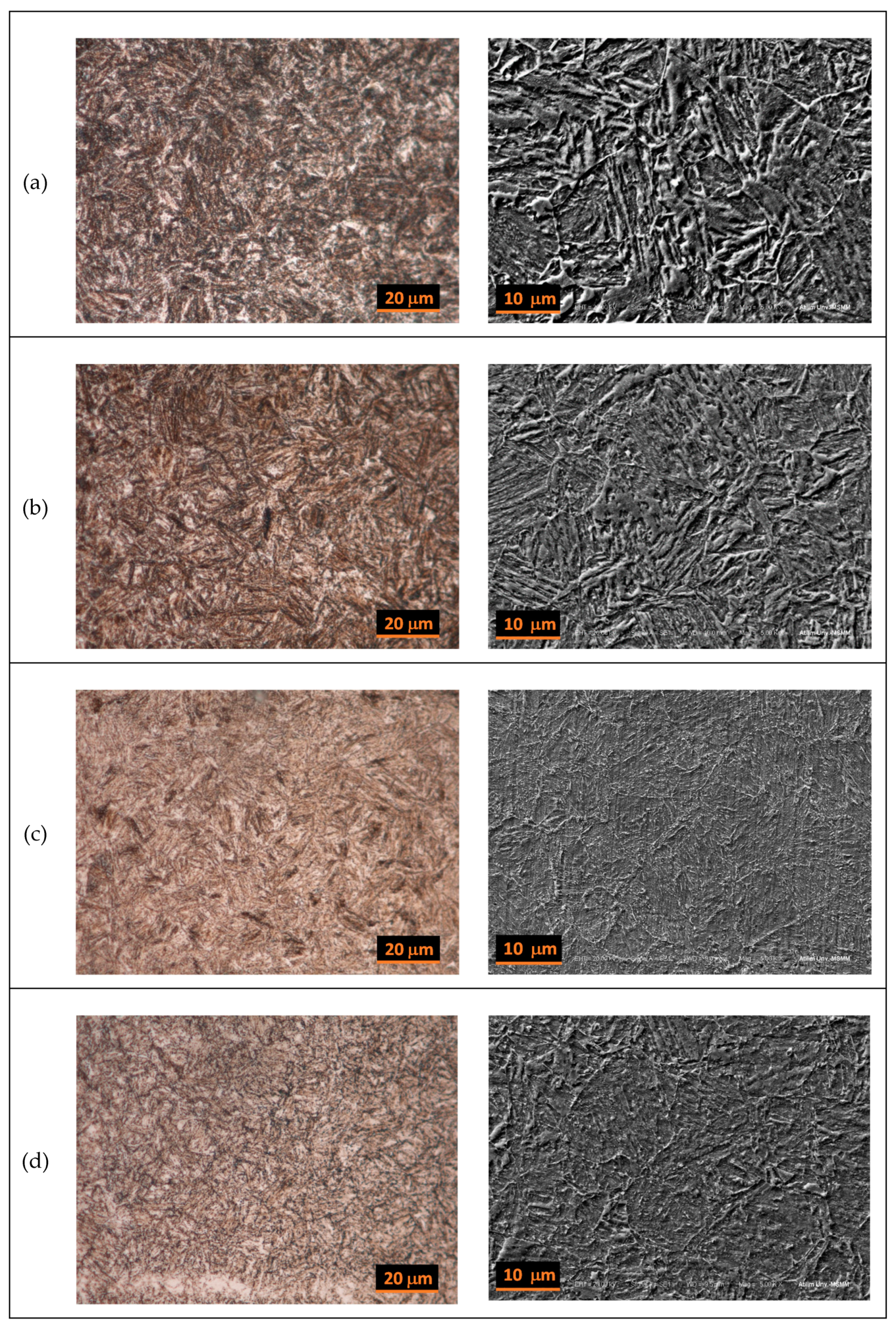
The optical and SEM microstructural images of the heat-treated samples are given in Figure 6. As targeted, it was observed that the 360 °C sample had a bainite microstructure (Figure 6a). The 320 °C sample was also essentially bainitic and it was finer structured (Figure 6b). It was not quite possible to resolve and identify the martensite present in this sample from the images. On the other hand, the microstructure of the 270 °C sample, as its treatment temperature was significantly below the Ms of 336 °C, was mostly martensitic (Figure 6c).

3.3. Results of the Ballistic Tests

The results of the ballistic tests are given in Table 4. The untreated (as-received) RHA sample caused an average of 31.0% loss in the kinetic energy of the fully charged 12.7 mm bullets fired from a distance of 25 m at it. As compared to the untreated RHA, the sample isothermally treated at 360 °C showed a higher ballistic performance and caused a 34.0% reduction in the kinetic energy of the bullets. The kinetic energy loss of the bullets fired at the 320 °C sample was 32.3%. On the other hand, the 270 °C sample exhibited a poorer ballistic performance by causing only a 25.2% loss in the kinetic energy. The ballistic performances of the isothermally treated and then tempered samples were similar to each other with 28.8% and 29.0% for the IT-320-T and IT-270-T samples, respectively. Given the fact that fully charged 12.7 mm bullets were used in the ballistic tests, the relatively small differences in the kinetic energy losses caused by the samples were still considered to indicate appreciable differences in their ballistic protection behavior.

3.4. Macro Examination of the Samples after the Ballistic Tests

After the ballistic tests, the holes created by the bullets on the test samples were examined. While the size and shape of the bullet entrance (hit) side of the holes were similar to each other, the bullet exit side of the holes exhibited significant differences among the samples, as shown in Figure 7a–f. In solely isothermally treated samples (IT-360, IT-320, and IT-270), the bullet exit sides of the holes were significantly larger than their entrance sides due to the fracture-induced material removal (Figure 7a–c). It was observed that the exit sides of the holes became larger as the amount of material removed increased with decreasing treatment temperature from 360 °C to 270 °C. Fracture and fragmentation was noted as the main mode of perforation in these samples.
The RHA sample, on the other hand, showed a completely different behavior. Instead of material removal by fracture, there was a significant amount of material flow parallel to the bullet direction by plastic deformation, resulting in very similar sized openings in both entrance and exit sides of the holes (Figure 7d). Tempering of the isothermally treated samples drastically changed their damage behavior. Similar to the RHA sample, these two samples also experienced significant plastic deformation (Figure 7e,f) rather than fracture. Hence, ductile hole growth was noted as the main mode of perforation in these three samples (RHA, IT-320-T, and IT-270-T).
Cross-sectional images of the holes, prepared as described in Figure 5, are given in Figure 8a–f. It was observed that the 360 °C sample showed a mixed behavior where, in addition to fracture, there was also some plastic deformation around the lower side of the hole, as seen in Figure 8a. Conforming the images given in Figure 7b,c, the images in Figure 8b,c show that the bullet impact essentially caused fracturing and material removal on the samples that were isothermally treated at 320 °C and 270 °C. On the other hand, the RHA sample and the samples tempered after the isothermal treatment showed significant plastic deformation, causing material flow along the bullet exit direction (Figure 8d–f).

3.5. Micro Examinations of the Hole Cross-Sections

A closer examination of the cross-sections of the holes was performed on the microstructural examination samples prepared from either the upper or the lower side of each cross-section, as shown in Figure 8a–f. For each sample, optical images scanning the sample surface were taken at 50× magnification and then they were integrated (stitched) to form general views of the samples depicted in Figure 9a–f.
Material flow, shear bands (white zones), and cracking were observed in the 360 °C sample (Figure 9a). On the other hand, the 320 °C sample showed very limited deformation and material flow as it lost material mostly due to fracture (Figure 9b). Extensive cracking and fracture were observed in the sample isothermally treated at 270 °C (Figure 9c). Although there were deformation bands, no cracking or fracture was present in the RHA sample and it was only plastically deformed flowing outwards (Figure 9d). Significant material flow and some cracking were observed in the samples that were tempered after the isothermal treatments (tempered 320 °C and tempered 270 °C samples), as shown in Figure 9e,f. In addition to the shear bands present within the deformed regions, there were also bands formed around the holes in contact with the perforating bullets.

4. Discussion

4.1. Factors Determining the Ballistic Protection Performance of an Armor Material

The ballistic protection performance of an armor material is essentially dependent on its capability to take over and dissipate the kinetic energy (or momentum) of the threat impacting its surface. When the impact takes places, the armor can elastically deform and revert the energy (momentum) back to the threat or it can dissipate the energy imparted onto it by (i) vibration and dampening, (ii) plastic deformation, and/or (iii) fracture and fragmentation. The mechanical properties and the mechanical behavior of the armor material at ballistic speeds determine which and how much of these mechanisms will operate and contribute to the dissipation of the imparted energy. Given the fact that all samples were perforated by the bullets in the current study (Figure 7a–f), it is imperative to consider plastic deformation and fracture as the two main mechanisms of energy annihilation since the role of elastic deformation or vibration would be negligible and not differentiating among the samples.
An examination of the holes on the IT-360 sample indicates that this sample suffered both fracture and some plastic deformation (Figure 7a, Figure 8a and Figure 9a). On the other hand, the imparted energy caused cracking, fracture, and material loss in the case of IT-320 and IT-270 samples (Figure 7b,c, Figure 8b,c, and Figure 9b,c). Meanwhile, the shape of the holes on the RHA sample (Figure 7d, Figure 8d and Figure 9d) indicate that most of the kinetic energy imparted onto this sample was consumed by its plastic deformation and material flow (ductile hole growth) rather than its fracture. The deformation behavior of the tempered versions of the isothermally treated samples (IT-320-T and IT-270-T) was also similar to that of the RHA sample (Figure 7e,f, Figure 8e,f and Figure 9e,f) with significant plastic deformation and material flow.
It is suggested that the relatively higher ballistic protection performance of the bainitic IT-360 sample can be linked to the fact that this sample experienced both plastic deformation and fracture, whereas the rest of the samples were either mainly deformed or fractured. Apparently, the effective operation of these two mechanisms together caused a higher decrease in the kinetic energy of the bullets fired at this sample in contrast to the other samples where only one mechanism operated.

4.2. Relations between Microstructure, Mechanical Properties, and Ballistic Protection Performance

The main findings of this study are summarized in Table 5, where the hardness and impact energy values of the samples are listed in the order of their decreasing ballistic protection performances. No sound correlation could be established between these values and the ballistic performances of the samples. For example, the 270 °C sample showed the poorest ballistic performance although it had the highest hardness among the tested samples. This implies that the ballistic protection performance of a material is actually dependent on its mechanical behavior at ballistic speeds (~900 m/s) and this behavior cannot be fully inferred from the mechanical properties determined at relatively static conditions. Obviously, the differences in the microstructures of the samples imposed differences in their mechanical behavior operating at ballistic speeds. Therefore, an attempt to relate the results of the ballistics tests to the conventional mechanical properties does not produce a correlation as the types and amounts of microstructural constituents differ from one sample to other and each microstructural constituent has its own peculiar high-speed mechanical behavior. Nevertheless, it is clear that the bainite microstructure is relatively more effective in slowing down the bullets as compared to the tempered martensite or bainite–martensite mixed microstructures.
The examination of the bullet holes created on the samples showed that, although the results of the conventional hardness and impact tests do not directly indicate the ballistic protection performance, these measurements still give an idea about the dominant mechanical behavior to be expected at ballistic speeds. The samples with relatively higher hardness and lower impact energy values (IT-270, IT-320, and IT-360) essentially fractured during perforation (Figure 7a–c), whereas the samples with the lower hardness and higher impact energies (IT-320-T, IT-270-T, and RHA) showed ductile deformation (Figure 7d–f).

5. Conclusions

RHA steel plates were subjected to various isothermal and tempering heat treatments to obtain samples with bainite and bainite–martensite mixed microstructures. Then, the ballistic protection performances of these samples were determined and compared with that of the regular RHA sample of tempered martensite microstructure.
  • It was found that the samples with essentially bainitic microstructures provided slightly higher ballistic protection than the regular RHA sample. This observation suggests that it may be possible to improve the ballistic performance through bainitic microstructures even in an armor steel of conventional chemical composition.
  • Although they had higher combinations of hardness and impact energy values, the ballistic performances of the isothermally treated samples decreased as the treatment temperature was lowered below the Ms temperature.
  • Within the limits (363–458 Brinell and 23.2–56.8 J) of this study, no correlation could be established between the ballistic protection performance and the hardness and impact energy values of the samples. It is concluded that the differences in the types and amounts of micro constituents of these samples imposed differences in their dynamic mechanical behavior at ballistic speeds (~900 m/s) and that it is not possible to infer these differences from the conventional mechanical properties determined at relatively static conditions.
  • The examination of the bullet holes showed that, although the results of the hardness and impact tests do not precisely predict the ballistic protection performances of the samples, these values can still indicate the type of mechanical behavior to be expected at ballistic speeds.

Funding

This research was funded by ROKETSAN Missile Industries Inc. (Ankara, Turkey). The APC was paid for by the author.

Acknowledgments

The author is grateful to K. Tur, M. Elmadağlı, and F. Güner for their assistance in the design of the study and interpretation of the results. K. Tur is also acknowledged for his help with the experimental work and proofreading of the manuscript. The author is thankful to Ö. Dinç, Y. Kazanç, and G. Özaltun for sample preparation and testing. The author expresses his sincere thanks to the personnel of the Ballistic Protection Center of ROKETSAN.

Conflicts of Interest

The author declares no conflict of interest.

References

  1. Carlucci, D.E.; Jacobson, S.S. Ballistics: Theory and Designs of Guns and Ammunition, 3rd ed.; Taylor & Francis: Boca Raton, FA, USA, 2018; pp. 377–379. [Google Scholar] [CrossRef]
  2. High Velocity Impact Dynamics, 1st ed.; Zukas, J.A. (Ed.) John Wiley & Sons: New York, NY, USA, 1990; pp. 65–105. [Google Scholar]
  3. Military Specification. Armor Plate, Steel, Wrought, Homogeneous; MIL-A-12560J (MR); U.S. Army Research Laboratory: Adelphi, MD, USA, 29 July 2009. [Google Scholar]
  4. Military Specification. Armor Plate, Steel, Wrought, High-Hardness; MIL-DTL-46100E (MR); U.S. Army Research Laboratory: Adelphi, MD, USA, 9 July 2008. [Google Scholar]
  5. Military Specification. Armor Plate, Steel, Wrought, Ultra-High-Hardness; MIL-DTL-32332 (MR); U.S. Army Research Laboratory: Adelphi, MD, USA, 24 July 2009. [Google Scholar]
  6. Srivathsa, B.; Ramakrishnan, N. Ballistic performance maps for thick metallic armour. J. Mater. Process. Technol. 1999, 96, 81–91. [Google Scholar] [CrossRef]
  7. Maweja, K.; Stumpf, W. The design of advanced performance high strength low-carbon martensitic armour steels: Microstructural considerations. Mater. Sci. Eng. A 2008, 480, 160–166. [Google Scholar] [CrossRef]
  8. Maweja, K.; Stumpf, W. The design of advanced performance high strength low-carbon martensitic armour steels: Part 1. Mechanical property considerations. Mater. Sci. Eng. A 2008, 485, 140–153. [Google Scholar] [CrossRef]
  9. Jena, P.K.; Mishra, B.; Babu, M.R.; Babu, A.; Singh, A.K.; SivaKumar, K.; Balakrishna Bhat, T. Effect of heat treatment on mechanical and ballistic properties of a high strength armour steel. Int. J. Impact Eng. 2010, 37, 242–249. [Google Scholar] [CrossRef]
  10. Kumar, R. Physical Metallurgy of Iron and Steel; Asia Publishing House: London, UK, 1968; pp. 186–187. [Google Scholar]
  11. Verhoeven, J.D. Fundamentals of Physical Metallurgy; Wiley: Singapore, 1975; pp. 500–508. [Google Scholar]
  12. Porter, D.A.; Easterling, K.E. Phase Transformations in Metals and Alloys, 2nd ed.; Chapman & Hall: London, UK, 1992; pp. 334–337. [Google Scholar]
  13. Abbaszadeh, K.; Saghafian, H.; Kheirandish, S. Effect of Bainite Morphology on Mechanical Properties of the Mixed Bainite-martensite Microstructure in D6AC Steel. J. Mater. Sci. Technol. 2012, 28, 336–342. [Google Scholar] [CrossRef]
  14. Niccols, E.H. Literature Review: Impact Toughness of Bainite vs Martensite; Technical Report WVT-TR-70012; US Army Armament Command: Watervliet, NY, USA, 1976. [Google Scholar]
  15. Barranco, M.; Cote, P.J.; Kapp, J.A. Tempering Effects For. Lower Bainite, Martensite and Mixed Microstructures on Impact, Fracture and Related Mechanical Properties of ASTM A723 Steel; Technical Report ARCCB-TR-92024; US Army Armament Research Development and Engineering Center: Picatinny, NJ, USA, 1992. [Google Scholar]
  16. Tomita, Y.; Okabayashi, K. Improvement in lower temperature mechanical properties of 0.40 pct C-Ni-Cr-Mo ultrahigh strength steel with the second phase lower bainite. Metall. Trans. A 1983, 14, 485–492. [Google Scholar] [CrossRef]
  17. Young, C.H.; Bhadeshia, H.K.D.H. The Strength of Mixtures of Bainite and Martensite. Mater. Sci. Technol. 1994, 10, 209–214. [Google Scholar] [CrossRef]
  18. Bhadeshia, H.K.D.H.; Garcia-Mateo, C.; Brown, P. Super Bainite Steels and Manufacture Thereof; World Intellectual Property Organisation (WIPO): Geneva, Switzerland, 2010; International Publication Number WO 2010/013054 A2. [Google Scholar]
  19. Bhadeshia, H.K.D.H.; Edmonds, D.V. Bainite in silicon steels: New composition-property approach Part 1. Metal. Sci. 1983, 17, 411–419. [Google Scholar] [CrossRef]
  20. Suzuki, T.; Ono, Y.; Miyamoto, G.; Furuhara, T. Effects of Si and Cr on Bainite Microstructure of Medium Carbon Steels. ISIJ Int. 2010, 50, 1476–1482. [Google Scholar] [CrossRef] [Green Version]
  21. Bhadeshia, H.K.D.H.; Edmonds, D.V. Bainite in silicon steels: New composition–property approach Part 2. Metal. Sci. 1983, 17, 420–425. [Google Scholar] [CrossRef]
  22. Super Bainite Armour Steel. Available online: https://www.ploughshareinnovations.com/technology/super-bainite-steel/ (accessed on 6 March 2020).
  23. Super Bainite Steel-perfection in Impenetrability. Available online: https://www.army-technology.com/features/featuresuper-bainite-steel-perfection-in-impenetrability-4346392/ (accessed on 6 March 2020).
  24. Burian, W.; Marcisz, J.; Garbarz, B.; Starczewski, L. Nanostructured Bainite-Austenite Steel for Armours Construction. Arch. Metall. Mater. 2014, 59, 1211–1216. [Google Scholar] [CrossRef] [Green Version]
  25. Chu, H.; Lillo, T.; Anderson, J.; Zagula, T. Development of a Scalable Thermomechanical Process (TMP) for Thick Bainitic Armor Steel. In Proceedings of the 2018 Ground Vehicle Systems Engineering and Technology Symposium (GVSETS), Novi Michigan, MI, USA, 7–9 August 2018. [Google Scholar]
  26. Sourmail, T.; Garcia-Mateo, C. Critical assessment of models for predicting the Ms temperature of steels. Comput. Mater. Sci. 2005, 34, 323–334. [Google Scholar] [CrossRef] [Green Version]
  27. Kim, H.; Inoue, J.; Okada, M.; Nagata, K. Prediction of Ac3 and Martensite Start Temperatures by a Data-driven Model Selection Approach. ISIJ Int. 2017, 57, 2229–2236. [Google Scholar] [CrossRef] [Green Version]
  28. Liu, C.; Zhao, Z.; Northwood, D.O.; Liu, Y. A new empirical formula for the calculation of Ms temperatures in pure iron and super-low carbon alloy steels. J. Mater. Process. Technol. 2001, 113, 556–562. [Google Scholar] [CrossRef]
  29. Barbier, D. Extension of the Martensite Transformation Temperature Relation to Larger Alloying Elements and Contents. Adv. Eng. Mater. 2014, 16, 122–127. [Google Scholar] [CrossRef]
  30. Lee, S.; Park, K. Prediction of Martensite Start Temperature in Alloy Steels with Different Grain Sizes. Met. Mat. Trans. A 2013, 44, 3423–3427. [Google Scholar] [CrossRef]
  31. van Bohemen, S.M.C. Bainite and martensite start temperature calculated with exponential carbon dependence. Mater. Sci. Technol. 2012, 28, 487–495. [Google Scholar] [CrossRef]
Figure 1. (a) Optical (1000×) and (b) SEM (5000×) microstructural images of the RHA plate showing its tempered martensite structure in the as-received condition.
Metals 10 00446 g001
Figure 2. (a) The custom-designed heat treatment setup used in this study. Top unit (austenitizing) is tilted for quick transfer of the samples to the bottom unit (salt bath—isothermal treatment) through the guides. (b) Computer drawing of the setup showing the impeller and the sample basket in the salt bath.
Metals 10 00446 g002
Figure 3. Graphical representation of the heat treatment conditions.
Metals 10 00446 g003
Figure 4. Schematic of the ballistic test setup.
Metals 10 00446 g004
Figure 5. Preparation of the cross-sectional examination samples.
Metals 10 00446 g005
Figure 6. Optical (left) and SEM (right) microstructural images of the ballistic test samples; (a) IT-360, (b) IT-320, (c) IT-270, (d) IT-320-T, and (e) IT-270-T. Optical images were taken at 1000× and SEM images were taken at 5000× magnifications.
Metals 10 00446 g006aMetals 10 00446 g006b
Figure 7. Bullet exit side views of the holes on the ballistic test samples: (a) IT-360, (b) IT-320, (c) IT-270, (d) RHA, (e) IT-320-T, and (f) IT-270-T.
Metals 10 00446 g007
Figure 8. Cross-sectional images of the holes on the ballistic test samples: (a) IT-360, (b) IT-320, (c) IT-270, (d) RHA, (e) IT-320-T, and (f) IT-270-T.
Metals 10 00446 g008aMetals 10 00446 g008b
Figure 9. Optical microscope images of the cross-sections of the perforations: (a) IT-360, (b) IT-320, (c) IT-320, (d) RHA, (e) IT-320-T, and (f) IT-320-T.
Metals 10 00446 g009aMetals 10 00446 g009b
Table 1. Chemical composition (wt.%) of the rolled homogeneous armor (RHA) steel plates.
CMnPSSiNiCrMoV
0.270.93<0.005<0.0050.301.401.130.460.07
Table 2. Heat treatment conditions applied to the RHA plates.
SampleIT-360IT-320IT-270IT-320-TIT-270-TRHA
Austenitization at 870 °C for 60 min-
Isothermal treatment for 60 min at 360 °C320 °C270 °C320 °C270 °C-
Tempering at 600 °C for 120 min----
Note: “✓”: applied, “-“: not applied.
Table 3. Hardness and −40 °C impact energies of the ballistic test samples.
SampleHardness (Brinell)−40 °C Impact Energy (J)
IT-360390.6 ± 5.423.2 ± 0.9
IT-320441.2 ± 3.728.7 ± 1.7
IT-270457.8 ± 5.030.5 ± 3.2
IT-320-T362.8 ± 3.156.8 ± 6.2
IT-270-T369.4 ± 5.648.0 ± 5.7
RHA363.2 ± 1.249.3 ± 6.1
Table 4. Results of the ballistic tests.
SampleAverage Kinetic Energy Loss of the Bullets (%)Change in Ballistic Performance with Respect to the RHA Sample (%)
RHA31.0 ± 2.3-
IT-36034.0 ± 2.0+9.9
IT-32032.3 ± 0.7+4.2
IT-27025.2 ± 1.4−18.6
IT-270-T29.0 ± 0.2−6.5
IT-320-T28.8 ± 1.5−7.2
The average bullet speed before impact was 902 ± 9 m/s.
Table 5. Hardness and impact energies of the samples listed in the order of their decreasing ballistic protection performances.
SampleAverage Kinetic Energy Loss of the Bullets (%)Hardness (Brinell)−40 °C Impact Energy (J) MicrostructureMain Mode of Perforation
IT-36034.0 ± 2.0390.6 ± 5.423.2 ± 0.9BainitePlastic Deformation and Fracture
IT-32032.3 ± 0.7441.2 ± 3.728.7 ± 1.7Mostly bainite with some martensiteFracture and Fragmentation
RHA31.0 ± 2.3363.2 ± 1.249.3 ± 6.1Tempered martensitePlastic Deformation and Ductile Hole Growth
IT-270-T29.0 ± 0.2369.4 ± 5.648.0 ± 5.7Tempered martensite with some bainitePlastic Deformation and Ductile Hole Growth
IT-320-T28.8 ± 1.5362.8 ± 3.156.8 ± 6.2Tempered bainite and martensitePlastic Deformation and Ductile Hole Growth
IT-27025.2 ± 1.4457.8 ± 5.030.5 ± 3.2Mostly martensite with some bainiteFracture and Fragmentation