Article

Flight Test of Autonomous Formation Management for Multiple Fixed-Wing UAVs Based on Missile Parallel Method

1
School of Electronics and Information, Northwestern Polytechnical University, Xi’an 710072, China
2
Department of Aerospace Engineering, College of Aerospace Engineering, Nanjing University of Aeronautics and Astronautics, Nanjing 210095, China
*
Author to whom correspondence should be addressed.
Drones 2022, 6(5), 99; https://doi.org/10.3390/drones6050099
Submission received: 14 March 2022 / Revised: 8 April 2022 / Accepted: 13 April 2022 / Published: 19 April 2022

Abstract

:
This paper reports on the formation and transformation of multiple fixed-wing unmanned aerial vehicles (UAVs) in three-dimensional space. A cooperative guidance law based on the classic missile-type parallel-approach method is designed for the multi-UAV formation control problem. Additionally, formation transformation strategies for multi-UAV autonomous assembly, disbandment, and special circumstances are formed, effective for managing and controlling the formation. When formulating the management strategy for formation establishment, its process is divided into three steps: (i) selecting and allocating target points, (ii) forming loose formations, and (iii) forming short-range formations. The management of disbanding the formation is formulated through reverse thinking: the assembly process is split and recombined in reverse, and a formation disbanding strategy that can achieve a smooth transition from close to lose formation is proposed. Additionally, a strategy is given for adjusting the formation transformation in special cases, and the formation adjustment is completed using the adjacency matrix. Finally, a hardware-in-the-loop simulation and measured flight verification using a simulator show the practicality of the guidance law in meeting the control requirements of UAV formation flight for specific flight tasks.

1. Introduction

Form formation management is an important research topic for multiple unmanned aerial vehicles (UAVs) flying in cooperative formation [1,2]. Because of the limited control of fixed-wing UAVs, their formation management is very different from that of quadrotor UAVs. By contrast, static and fixed-wing UAVs cannot wait for other UAVs during formation [3], which makes stable and reliable formation challenging.
In recent decades, many scholars have researched the formation of fixed-wing UAVs. Zhang [4] proposed a proportional integral–derivative (PID) integrated control method based on robust control; this comprehensive control method improves the hit rate and flight stability of UAV formation, reduces the dynamic response of the steady-state error, and shortens the convergence time, but the influence of the coupling effect of the integrated controller on the entire control system was not considered in the corresponding experiment. Kada [5] proposed (i) a smooth distributed cooperative control method for multiple aircraft (such as UAVs) based on multi-agent system (MAS) consistency and (ii) a smooth distributed consistency algorithm, as well as designing a formation control model for three-dimensional (3D) geometry tracking; however, the disadvantage of this approach is that it fails to consider (i) formation tracking in the case of external interference and (ii) obstacle avoidance among flying agents. Wang [6] analyzed the optimality of formation configuration, provided an optimal formation design strategy for multi-UAV patrol tasks, and developed a model prediction trajectory replanning algorithm. However, the disadvantages of this approach are that it (i) considers only the mission and motion planning level and (ii) does not involve low-level flight-control problems. Reference [7] proposed a robust decentralized tracking control scheme for a large-scale UAV-formation network control system and verified it in such a system.
Research on formation maintenance and transformation remains sparse. Proposed herein is a formation management method based on cooperative waypoint following. Additionally, formation reconfiguration strategy is designed considering how some typical unexpected situations influence cooperative formations. Combining the guidance law of the parallel-approach method [8,9] and the calculation method of virtual dynamic tracking points, a method is proposed for cooperative path-point following in formation control [10,11,12] to realize multi-machine formation flight of fixed-wing UAVs. It has the advantages of fast tracking response in the low-altitude formation flight, and rapid formation reconstruction in unexpected situations. Finally, the stability and agility of the guidance law in formation cooperative control are verified by hardware-in-the-loop [13,14,15] simulation and flight-test measurements.
Based on the flight control of a single fixed-wing aircraft [13,14,15], this paper designs a layered control framework, as shown in Figure 1. The control framework includes four submodules: the intermachine communication module, the cooperative waypoint-following control module, the cooperative formation module, and the stabilization loop control module. After receiving the instruction to start the formation, the cooperative formation module generates the desired waypoints for the UAVs. Compared with trajectory tracking, waypoint tracking is more widely used in aviation, and a series of static waypoints often represent common single-plane flight tasks. Waypoint tracking is used more widely in aviation, and a series of static waypoints often represent common single-plane flight tasks.

2. Design of Guidance Law and Verification by Simulation

2.1. Design of Guidance Law

The required lateral movement is determined by calculating virtual dynamic tracking points according to the formation relative distance of the formation, and the virtual dynamic tracking points are those of the wingmen.
Assuming that the UAVs are all mass points when flying in formation, as shown in Figure 2, in the case of two UAVs, let point A be where the leader is located, let point B be where the virtual dynamic tracking point is located, and let point C be where the wingman is located. Define the coordinate formation system O f X f Y f Z f fixed to the lead plane L: O f X f is parallel to the direction of the speed vector of the lead plane and points forward; the axis O f Y f is perpendicular to O f X f and points to the right of the flight direction; the axis O f Z f is perpendicular to O f X f Y f and points downward. Points A and B are on concentric circular arcs whose lengths are Δ x and arc, respectively, and the concentric circular arcs are on O f X f Y f ; Δ y is the length of the straight line of the leader aircraft to the arc, R L is the flight radius of the lead aircraft, R is the radius of the concentric circular arcs, and φ is the included angle of point A and B. In this coordinate system, point B is relative to point A and its positional differences are Δ x e r r and Δ y e r r , whose lengths can be obtained geometrically.
When φ is small, we have
{ Δ x e r r = a r c Δ y e r r = Δ y
When φ is larger, we have
{ Δ x e r r = a r c φ sin φ Δ y e r r = Δ y a r c φ ( 1 cos φ )
where a r c is calculated as
a r c = R φ
Therefore, the distance difference [ x e r r y e r r ] T between the virtual dynamic tracking point B and the leader A can be obtained through the distance [ Δ x Δ y ] T set for the formation.
The transformation matrix for converting from the formation coordinate system x f O f y f to the ground coordinate system x g O g y g is
L g f = [ cos ψ L sin ψ L sin ψ L cos ψ L ]
where ψ L is the angle between the two vector axes O x f and O x g .
Then, the coordinate difference between points A and B in the ground coordinate system is
[ x e r r y e r r ] = L g f [ x e r r y e r r ]
As can be seen, the coordinates of point B are
[ x L y L ] = [ x L x e r r y L y e r r ]
Letting the distance difference between points B and C be [ P x P y ] T , we obtain
[ p x p y ] = [ x F x L y F y L ]
The key to designing the guidance law for the wingmen in the formation is to convert the relative distances between the UAVs and the target tracking points, the velocity vector deviations, the heading deviations, and other information into guidance commands. The algorithm for the guidance law can be designed using either geometric methods or control-theory methods. The former use the geometric relationship between UAV and target point to design the guidance law, characterized by convenient analysis and simulation; geometric methods are the ones used most commonly in engineering practice.
The geometric parallel-approach method is used as the guidance law for cooperative formation. The parallel-approach method was designed originally for missile interception and attacking targets, and the resulting trajectories are relatively straight. The specific implementation of the parallel-approach method herein is to keep the line of sight from UAV to target point unchanged during flight, and the line-of-sight angle forms a set of parallel lines in space, as shown in Figure 3.
In Figure 3, v m is the velocity vector of the UAV tracking the target point whose azimuth angle is η m . The velocity vector V d of the UAV has components v i that are equal to v m , i.e.,
v i = v m
In the formation of the lead-aircraft–wingman control mode selected herein, the lead aircraft sends real-time status information through an airborne data link, and the wingmen in the formation obtain v m and η m of the lead aircraft through calculation.
The realization of the parallel-approach method in this paper is to keep the line-of-sight angle q between the wingman and the dynamic tracking point unchanged during the flight. In the ground coordinate system, the line-of-sight angle between the wingman and the dynamic tracking point is ψ e , and the angle between the velocity vector and the line-of-sight direction is defined as the lead angle, as shown in Figure 4. Then, the flight speed of the wingman is V F , the speed azimuth is ψ F , and the lead angle is η F ; the flight speed of the dynamic tracking point is V L , the speed azimuth is ψ F , and the lead angle is η F . The horizontal straight-line distance between the wingman and the dynamic tracking point is d h o r i z .
The following geometric relationships exist between the lead angle, velocity azimuth angle, and line-of-sight angle of the wingman and the dynamic tracking point:
{ η F = ψ e ψ F η L = ψ e ψ L
The relative motion speed d ˙ h o r i z of the wingman and the dynamic tracking point is
d ˙ h o r i z = V F cos η F V L cos η L
The change law of the line-of-sight angle between the wingman and the dynamic tracking point is
ψ ˙ e = 1 d h o r i z ( V L sin η L V F sin η F )
These two formulas are the guiding equations of the parallel-approach method.
The constraints of the equation are:
ε = ψ ˙ e = 0
In the formula, ψ e can be calculated from the position of the wingman and the position of the dynamic tracking point. As shown in Figure 2, the coordinate difference between points B and C is [ P x P y ] T , and the positional relationship is shown in Figure 4, then the calculation of ψ e is
ψ e = arctan P y P x
V L sin η L is the projection of the velocity of the dynamic tracking point in the normal direction of the line of sight, v n o r m a l , shown in Figure 4, using the calculation method of vector dot product. Let the position difference vector P = [ P x P y ] T between the wingman and the virtual dynamic point, the speed vector of the virtual dynamic point is v = [ v n v e ] T , then P v = | P | | v | cos η L , where | v | cos η L is the speed of the dynamic virtual point V L on the vector P Tangential projection of v h o r i z .
v h o r i z = | v | cos η L = ( P x v n + P y v e ) | P |
The vector of velocity v h o r i z is expressed as
v h o r i z = [ P x v h o r i z | P | P y v h o r i z | P | ] T
The normal projection velocity vector of the velocity V L of the dynamic virtual point on the vector P is denoted as v n o r m a l = v v h o r i z . The modulus of v n o r m a l is recorded as | v n o r m a l | , which is the numerical value of | v n o r m a l | , and the expected heading control command of the wingman can be obtained as
ψ F c = ψ e arcsin | v n o r m a l | V F

2.2. Simulation Verification of Guidance Law

Here, we introduce the method of using software modeling and simulation to simulate the built formation model, which is an effective way to test the algorithm’s robustness and provide data support for the subsequent actual flight. The specific method is to model the stand-alone control models of the lead plane and the wingmen under MATLAB/Simulink and perform modular encapsulation processing to facilitate the subsequent expansion of the formation scale. At the same time, the guidance-law part is also modeled to simulate the control of the aircraft by the guidance law and the control law during actual flight. Finally, the aircraft’s control, trajectory, and attitude parameters are output for subsequent data analysis and visual trajectory analysis.

2.2.1. Construction of Simulation Model

The guidance-law simulation is mainly to verify the performance of the guidance-law module. Here, we establish a particle model of a sample UAV. The channel dynamics of the leader and wingman control models are simulated using transfer functions, and their response is the same as the current design control. The law remains the same. Each control channel of the UAV in the particle model can respond to the command signal given by the guidance law in time and at the same time directly output basic information such as altitude, speed, and attitude angle. The output form is convenient for subsequent analysis of the simulated flight trajectory.
The lateral-heading control channel’s modeling involves the roll-angle-rate control loop as a first-order inertial link because bank-to-turn is used in control herein to control the heading channel. Therefore, the modeling of the heading channel can be realized based on the roll channel and on the complex number field; the physical relationship is
ψ ( s ) = g tan ϕ v g 1 s
where ψ is the heading angle, ϕ is the roll angle, v g is the target speed, and g is the acceleration of gravity.
As shown in Figure 5, the model input is the roll-angle command ϕ c of the formation guidance-law module, and the outputs are the UAV model’s roll angle and heading angle. The intermediate variable of the control channel is the control of the angular roll rate, and we use a first-order transfer function with a bandwidth of ω n = 6 to simulate the dynamics of the angular-rate channel.
The modeling of the longitudinal pitch control channel involves regarding the pitch-angle-rate control loop as a first-order inertial link, as shown in Figure 6. The input is the pitch-angle command θ c of the formation guidance-law module, and the output is the pitch angle of the UAV model. The intermediate variable of the control channel is the pitch rate, and the modeling uses a first-order transfer function with a bandwidth of ω n = 7 to simulate the dynamics of the angular-rate channel.
The longitudinal velocity control channel is modeled by considering acceleration as a first-order inertial link, as shown in Figure 7. The input is the target-speed command v g c of the formation guidance-law module, and the output is the indicated airspeed of the UAV model currently flying. The acceleration is modeled using a first-order transfer function with a bandwidth of ω n = 3 to simulate its dynamics.

2.2.2. Results of Simulation of Guidance Law

The formation guidance law can be simulated by building the leader–follower formation simulation model. The intermediate variables of the flight trajectory and guidance law are stored temporarily in the MATLAB workspace, and various output data can be visualized and analyzed by graph-drawing scripts.
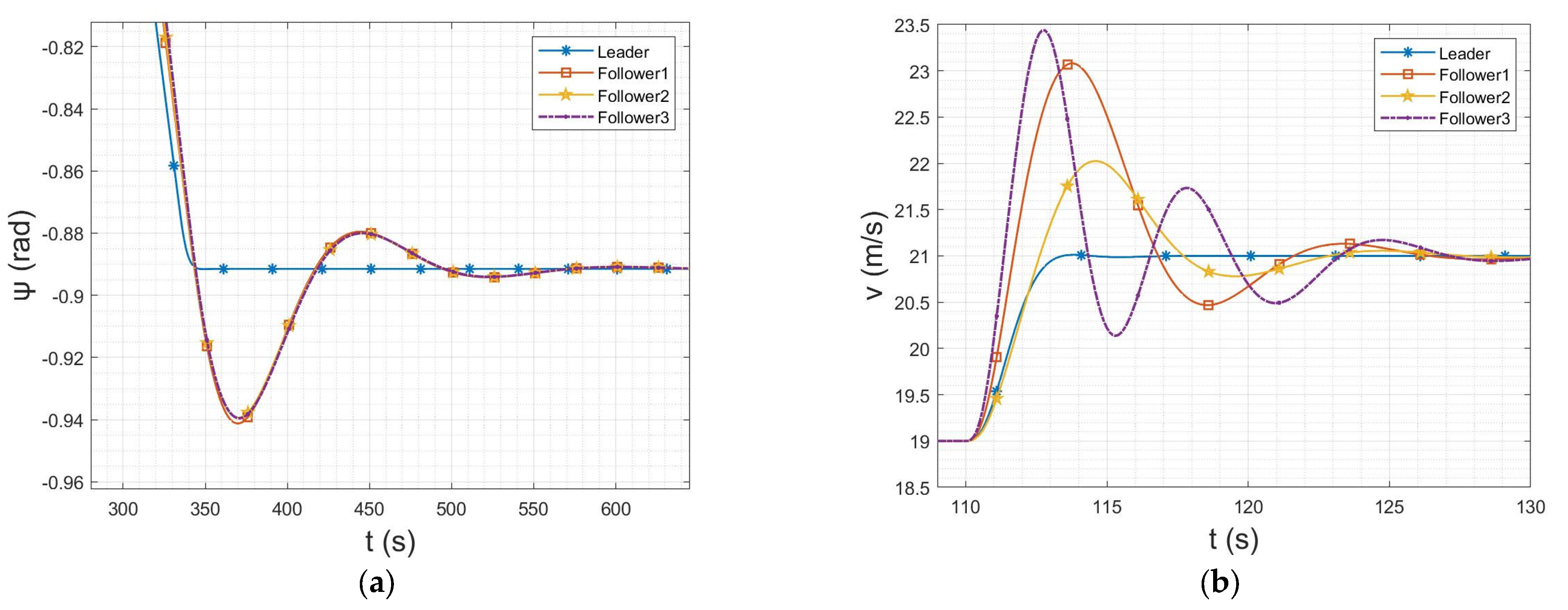
The core index of the guidance law of the parallel-approach method is the tracking effect of the heading channel. Figure 8 shows the dynamic change in the heading angles and velocities of the leader and the three wingmen with time. When the heading of the leader changes rapidly, the heading channels of the three wingmen respond and track it in time. When the lead plane’s heading becomes stable, the wingmen follow it smoothly after a small amount of overshoot in time.
In summary, the guidance law designed herein leads to a good formation and meets the requirements of fast response and stable tracking. Therefore, it can be used in the subsequent semiphysical simulation and actual flight.

3. Formation Management and Control

The flight mission of the leader in the cooperative formation [16,17,18] is described by a set of waypoints known as a waypoint list. After switching to fixed-wing mode, the lead pilot executes a mission route consisting of waypoints, flying to each waypoint in the list in turn. Before the wingmen enter formation mode, there are also waypoints to maintain normal fixed-wing flight. The waypoints in the lead waypoint list are represented using the position vector
p i = ( x i , y i , z i ) T ,
and those of the wingman is represented by the position vector
p f i = ( x i , y i , z i + d z i ) T ,
where d z is the cross-track error of the wingman waypoint relative to the leader in the vertical direction, thereby allowing calculation of the list of waypoints that each wingman flies before entering formation mode.
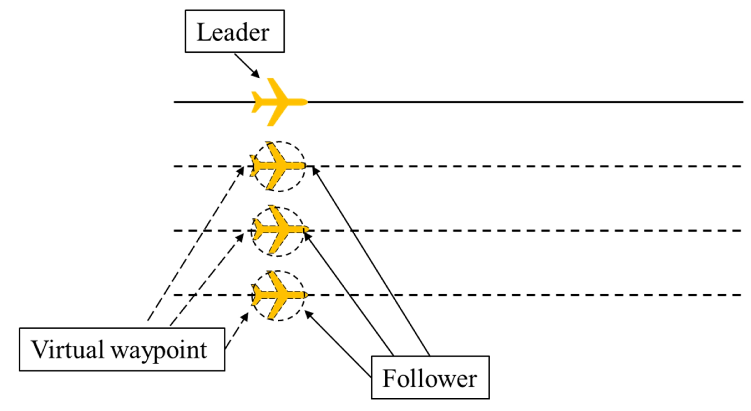
The cooperative formation-management method [19,20,21,22] herein involves the lead plane flying in formation with the wingmen in the link by managing a set of cooperative waypoints. The lead plane coordinates and moves the set of waypoints when formation changes are required. As shown in Figure 9, a group of parallel cooperative path points is generated by the wingmen following the leader, and a straight formation is formed.

3.1. Formation Keeping Based on Coordinated Waypoints

The formation maintenance of cooperative formations is studied in the formation coordinate system. As the coordinator, the lead aircraft generates a list of cooperating waypoints by adjusting their positions, and it sends it to the corresponding wingmen in the link through the intermachine communication module. The wingmen then extract the corresponding waypoints from the list of cooperative waypoints assigned by the lead plane according to its own, thereby realizing coordinated formation flight. Based on this method, we design the following three types of formation.
  • Linear formation. In the formation coordinate system, the position coordinates of the lead aircraft are (0, 0), those of the first cooperative path point are (0, xoffset), and those of the other i cooperative path points are (0, xoffset × i). We then construct the list of cooperative waypoints for a straight-line formation. Figure 10 shows the relationship of coordinated waypoints in straight horizontal formation.
2.
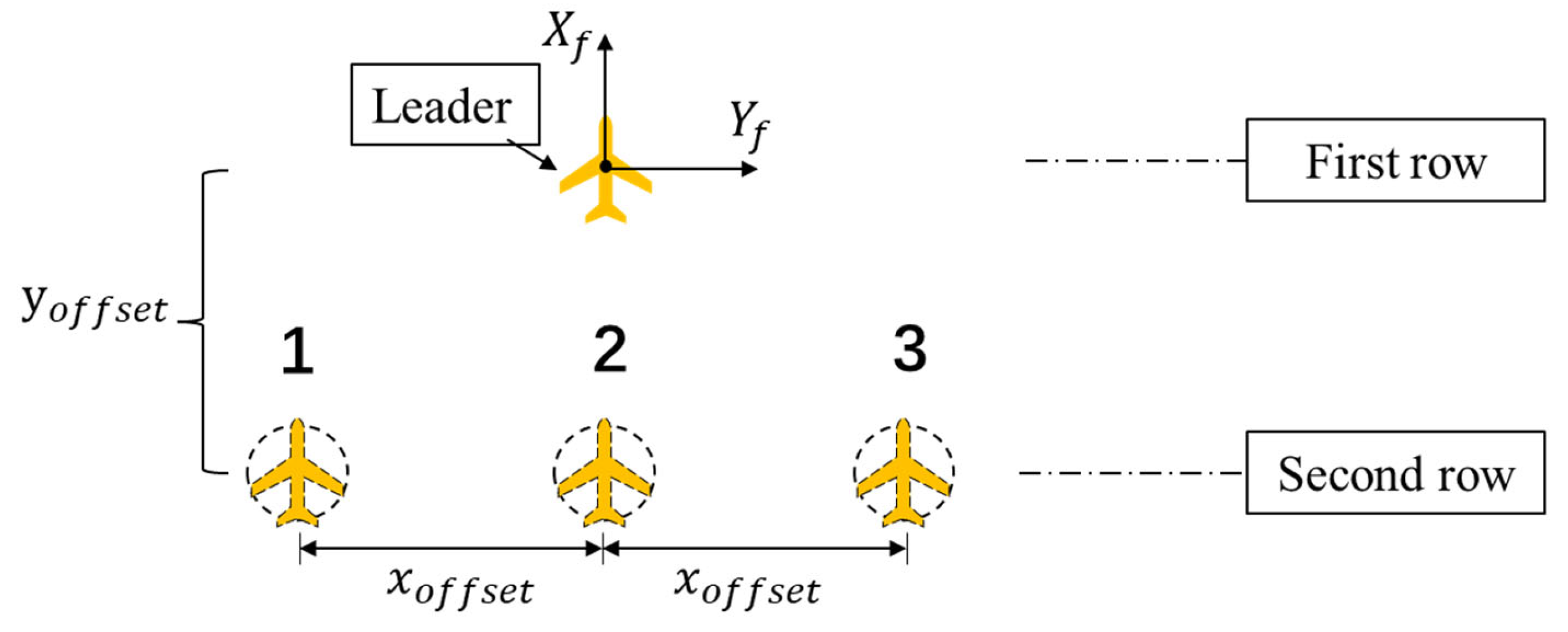
Triangular formation. In the formation coordinate system, the position coordinates of the lead aircraft are (0, 0), and there are at most (2n−1) cooperative waypoints in n lines, i.e., one line has one cooperative waypoint, and two lines have three cooperative waypoints. The y-axis coordinate interval between every two rows of collaborative path points is yoffset, and the x-axis coordinate interval between every two columns of collaborative path points is xoffset. A list of cooperating waypoints for a triangular formation can be constructed from this. Figure 11 shows the relationships of cooperating waypoints in horizontal triangular formations.
3.
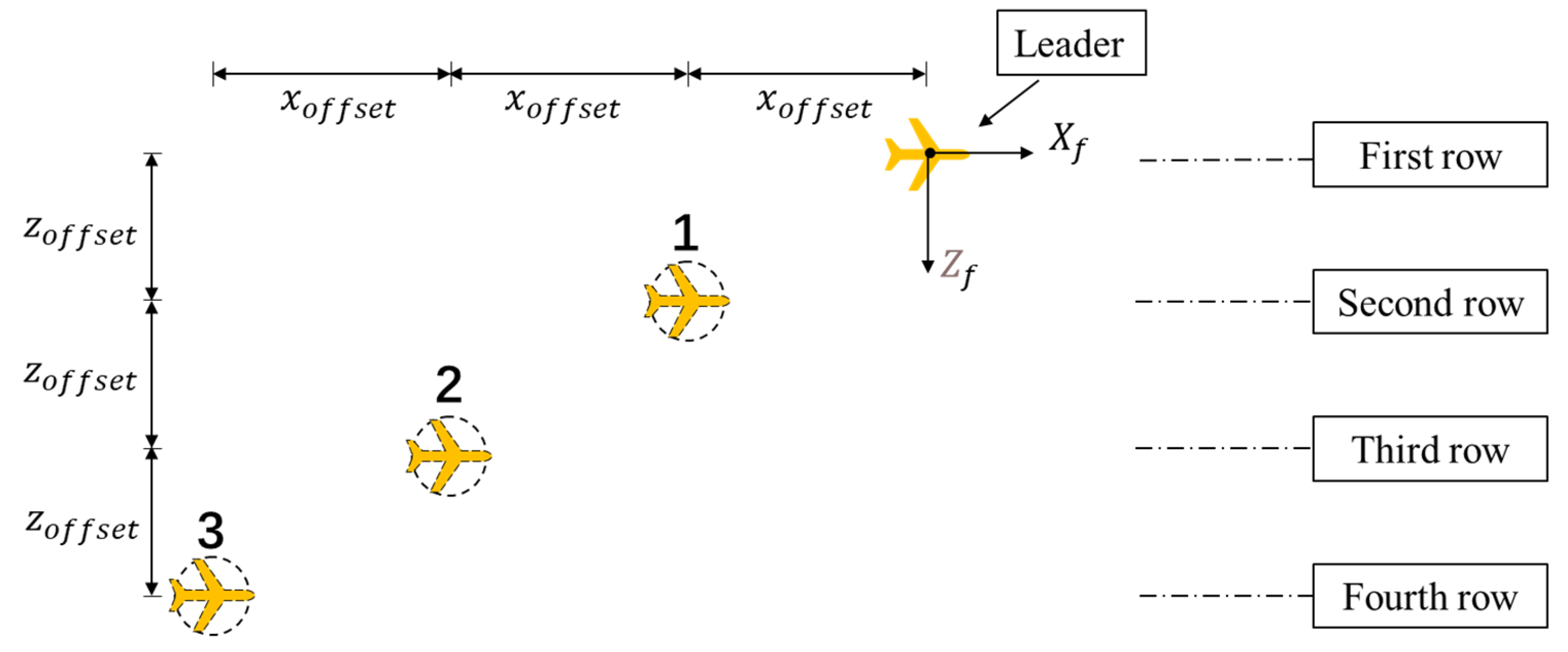
Stepped formation. A stepped formation is 3D, and in the formation coordinate system, the position coordinates of the leader are (0, 0) and each line has only one collaborative path point. As shown in the plan view of the stepped formation in Figure 12, the y-axis coordinate interval between every two rows of cooperative waypoints in the horizontal direction is yoffset, and the x-axis coordinate interval between every two columns of cooperative waypoints is xoffset. The side view of the stepped formation in Figure 13 shows that in the vertical direction, the z-axis coordinate interval between every two rows of cooperative path points is zoffset, and the z-axis coordinate interval between every two columns of cooperative path points is xoffset. A list of cooperating waypoints for the stepped formation can be constructed from this.
The formations mentioned above are three common ones in which the target tracking position can be determined by moving several waypoints on the spatial geometric position. Each wingman invokes the guidance-law algorithm according to its position and the positional relationship with the reference cooperative waypoint, and it controls the speed and attitude of its UAV to reach the desired position and form a specific formation.

3.2. Research on Formation Transformation Method of Cooperative Formation

In many mission scenarios, UAVs must form different formations to adapt to changes in the mission, which requires research on changes of collaborative formations. After creating a coordinated formation, the UAVs will continue to fly in the existing formation until a new mission requirement arises. Herein, a command from the ground-station software initiates a change in formation. For the coordinated formation of fixed-wing UAVs, the under-actuation and control limitations of the fixed-wing make it impossible to form trajectories from all initial positions to the desired formation; the only possible trajectories involve movement that maintains normal airspeed while approaching the desired location. Additionally, the intermediate transition process of cooperative formation change is very important [23,24,25,26], and it is necessary to consider possible collisions in the process of short-range formation change. According to the control strategy of formation keeping, we design a method for changing formation while also preventing collisions.
Before discussing the formation transformation method, we define the standard for forming a close-range formation. The current position of the center of mass of each wingman is p i , which includes the 3D position information, i.e.,
p i = ( x f i , y f i , z f i ) T
The location of each collaborative waypoint is
w i = ( x w i , y w i , z w i ) T
and the position error distance d e r r of a wingman and a cooperative waypoint in the horizontal direction determines whether the formation forms a tight formation on the X f O f Y f surface, where
d e r r = ( x f i x w i ) 2 + ( y f i y w i ) 2
We define the variable k to indicate whether the cooperative formation has formed a tight formation; k = 0 means that a wingman has not reached the cooperative target waypoint in the horizontal direction, whereas k = 1 implies that the wingman has reached the cooperative target waypoint in the horizontal direction and is now partnered with the leader. The value of k is judged by the relay method, with the judgment condition depending on the position error distance d e r r between the wingman position and the cooperative path point; we have
k = { 0 , i f ( d e r r > r max ) 1 , i f ( d e r r r max )
where rmax is the distance difference between judging whether the wingman reaches the cooperative path point, which is related to the UAV’s wingspan and formation spacing; for the actual flight, we use r max = 2 m .
The formation transformation method [27,28,29,30] for cooperative formation proposed herein involves performing formation transformation in the horizontal direction first and then in the vertical direction when the wingmen in the horizontal direction reach the constraint condition of close formation. The specific method is when it means that the wingman has not yet reached the cooperative target waypoint in the horizontal direction, and the control of the altitude channel is the height of the wingman waypoint, which means that the formation has completed the close formation in the horizontal direction. At this time, the wingmen set the control target of the altitude channel. To correspond to the heights of the cooperative waypoints, the transformation process is as shown in Figure 14.
As an example to illustrate the process of formation transformation, we take the transformation from a linear formation to a stepped formation. As shown in Figure 15, the formation keeps flying in a straight formation until time t1, and it begins to adjust the flight altitude of each wingman to the corresponding waypoint altitude. At time t2, the lead plane starts to redistribute the list information of the cooperative waypoints, transforming from a linear formation to a stepped one. At time t3, the positions of the cooperative waypoints are reassigned, and the wingmen begin to track the new cooperative waypoints. At time t4, the horizontal direction satisfies the constraints for a tight formation. After that, the vertical formation height control is carried out to meet the corresponding vertical spacing requirements of the stepped formation. After this, the formation has completed a transformation. The advantage of this method is that in the formation transformation process, it effectively reduces the probability of collision between the UAVs in short-range formation.

4. Formation Reconfiguration Strategy

The coordinated formation of UAVs involves some complex flight environments; there is a certain probability that some UAVs will suffer structural damage or power failure during the flight mission. Some complex electromagnetic environments may also cause the loss of communication links. These contingencies must be incorporated into the formation control strategy to complete the established formation flight mission.
To this end, we design a formation reconstruction strategy for some typical unexpected situations, which we divide into two types: (i) data-link topology damage and (ii) UAV self-failure. The data links use the mesh networking mode with antidestruction characteristics for this topic. In cases where there is no direct path between the transmitting node and the target node, automatic path searching can be enabled to find and provide path information to ensure that data are delivered to the destination node. By discovering unknown paths automatically and using the best one to transfer the data to the expected destination effectively, the redundancy of the data channel can be maintained when the data-link topology is damaged. As shown in Figure 16, there are multiple redundant channels for the communication between each UAV and the others. Taking the communication connection from vehicle A to vehicle C as an example, there are three paths in the link that can reach vehicle C, i.e., ABC, AFC, and AEDC; therefore, if the communication of a node is damaged, it will not affect the data transmission from vehicle A to vehicle C.
Failure of a UAV itself is divided into (i) lead-aircraft failure and (ii) wingman failure. In the coordinated formation of leader–follower mode, all the wingmen receive the position information of the leader in real-time. When more than λ communication cycles, the wingman still does not receive the leader’s data, and the leader is considered to be damaged. The follower with the minimum ID number in the link then acts as the leader; the other wingmen begin to receive the control information from the new leader, who also begins to output the list of cooperative waypoints.
In coordinated formation flight in leader–wingman mode, the wingmen far outnumber the leader, so the probability of a wingman being damaged is higher. When flying in a coordinated formation, the lead plane maintains a status table of whether each wingman is online. This status table is calculated based on the heartbeat packets sent by the wingmen to the lead plane. The specific logic is as follows: if the lead plane continues to receive a wingman’s heartbeat packet for time Tmin, then add this wingman to the online status table; if the lead plane does not receive a wingman’s heartbeat packet for time Tmax, then remove this wingman from the online status table. Here, Tmin is the shortest time for the lead plane and a wingman to establish a stable connection, and Tmax is the longest waiting time for the lead plane and a wingman to lose the connection; these two times are set according to the specific indicators of the data links. Therefore, when a wingman loses connection, the leader must remove it from the online status table, and the formation’s coordinated waypoint list is also adjusted accordingly. As shown in Figure 17, if vehicle 2 is damaged, then vehicle 3 moves to take its place.

5. Hardware-In-The-Loop Simulation

5.1. System Composition

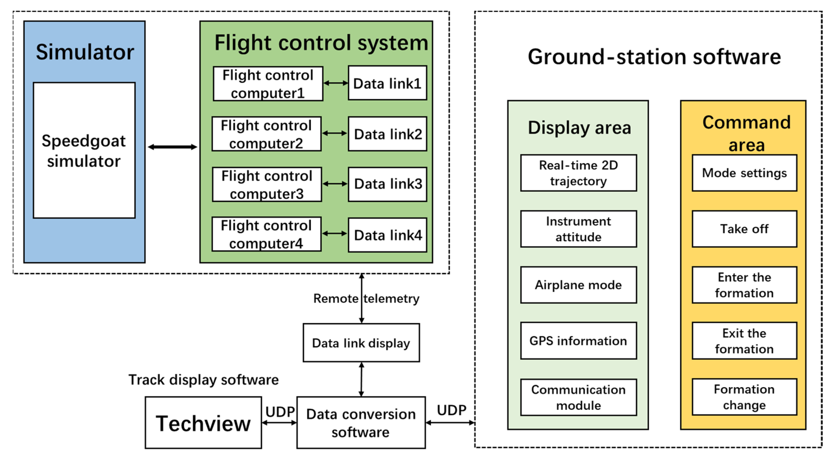
The semiphysical simulation system consisted of a simulation machine, a flight-control system, ground-station telemetry software, trajectory display software, and data-link communication equipment. The relationship among the different approaches is shown in Figure 18. The nonlinear six-degrees-of-freedom dynamic model of the UAV ran in the simulator, and the flight-control computer received the model data of the simulator for calculation. The command signal was output to the simulator to control the model. The data links were responsible for the communication between the flight-control computers and the ground-station software. The latter was divided into a display area and a command area: the display area displayed status information about the UAV flight, while the command area contained common remote-control commands to control the UAV formation. Finally, the Tacview trajectory-display software can display the flight trajectories of all the UAVs in the formation, thereby showing the formation more intuitively.
The equipment connection relationship of the constructed semiphysical simulation system is shown in Figure 19. The simulation machine used the Speedgoat real-time simulation platform. The ground-station computer was responsible for starting the simulator, running the ground-station software, and establishing communication with the simulator through network protocols. The ground-station computer was connected to a communication node of the data communication link to establish wireless communication with all flight-control computers participating in the simulation; communication between the simulator and the flight-control computers was carried out through an RS422 serial port.
The Speedgoat real-time simulation system is the official hardware platform of MATLAB/Simulink, and its operating system and software were developed by MathWorks and integrates MATLAB/Simulink seamlessly. The simulation system used an Intel processor and had powerful computing ability. All the logic was written in Simulink, and there was no need to write much code; the model could also be converted directly into real-time code for execution. This project used the Baseline-S basic-version simulator from Speedgoat, which is small and easy to move, weighing only 2.56 kg. It has two RS232 ports and three USB ports, which can be connected to multiple UAVs simultaneously.
The flight-control computer and the data communication links constituted the flight-control system. We used four sets of flight-control systems to simulate the formation of four aircraft. Each control system was connected to the Speedgoat real-time simulation system, receiving simulation data and controlling the dynamic model running in the simulator. The data communication links click the four sets of flight-control computers with the ground-station computers for networking communication.

5.2. Semiphysical Simulation Process

The flight-control system had to be started first to perform semiphysical simulation. After establishing a connection with the ground-station software, we set the flight-control system to the hardware-in-the-loop simulation mode, we then started the Speedgoat simulator, whereupon the UAV model in the simulator started to run and output data to the flight-control computer. After the ground-station software had checked that the flight-control computer system was in a normal state, each UAV model took off in sequence, and then a formation start command was sent in fixed-wing mode to enter the formation simulation verification.
The semiphysical simulation was a desktop simulation verification link before the actual flight test in the field, and it was necessary to test the scenes used in the flight accordingly. Herein, we report the semiphysical simulation of the following scenarios.
  • Case 1: Simulation of formation-mode flight
This simulation was aimed at multiple UAVs flying in cooperative formation, with a two-aircraft formation and a four-aircraft formation used as the research objects to conduct semiphysical simulations. The specific operation was for each UAV to takeoff according to the process and enter the fixed. Start the coordinated formation flight mode after the wings are in the state. Figure 20 shows the simulation results from the perspectives of the ground station (Figure 20a) and the Tacview trajectory-display software (Figure 20b) in cooperative formation mode. As can be seen, each wingman maintained a fixed distance from the leader to fly cooperatively.
  • Case 2: Simulation of formation change
The simulation of formation transformation verified the proposed method for transforming the cooperative formation. First, the UAVs were operated to form a stable formation, whereupon the ground-station software issued the command for formation transformation. The transformation of the four-machine formation from the triangular formation to the stepped formation as the research object shows the transformation results in Figure 21.
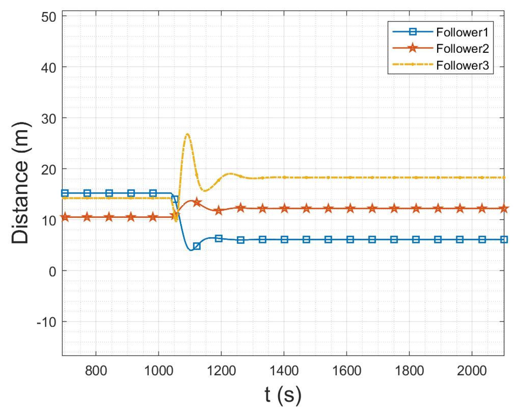
The position changes in the formation transformation simulation are related to the formation before and after the transformation, as shown in Figure 22, where the ordinate is the position difference between wingman and leader during formation flight. During triangular formation flight, the three wingmen were distributed behind the leader: follower 2 was the closest to the leader and was located directly behind it, and followers 1 and 3 were on either side of follower 2. After the formation had changed to the stepped formation, the three followers were distributed evenly on one side of the leader plane in turn and flew at fixed distances; follower 3 was on the outermost side of the formation and farthest from the lead plane. Figure 22 shows that the trajectories of position movement during the formation transformation were relatively stable with no rapid jumps.
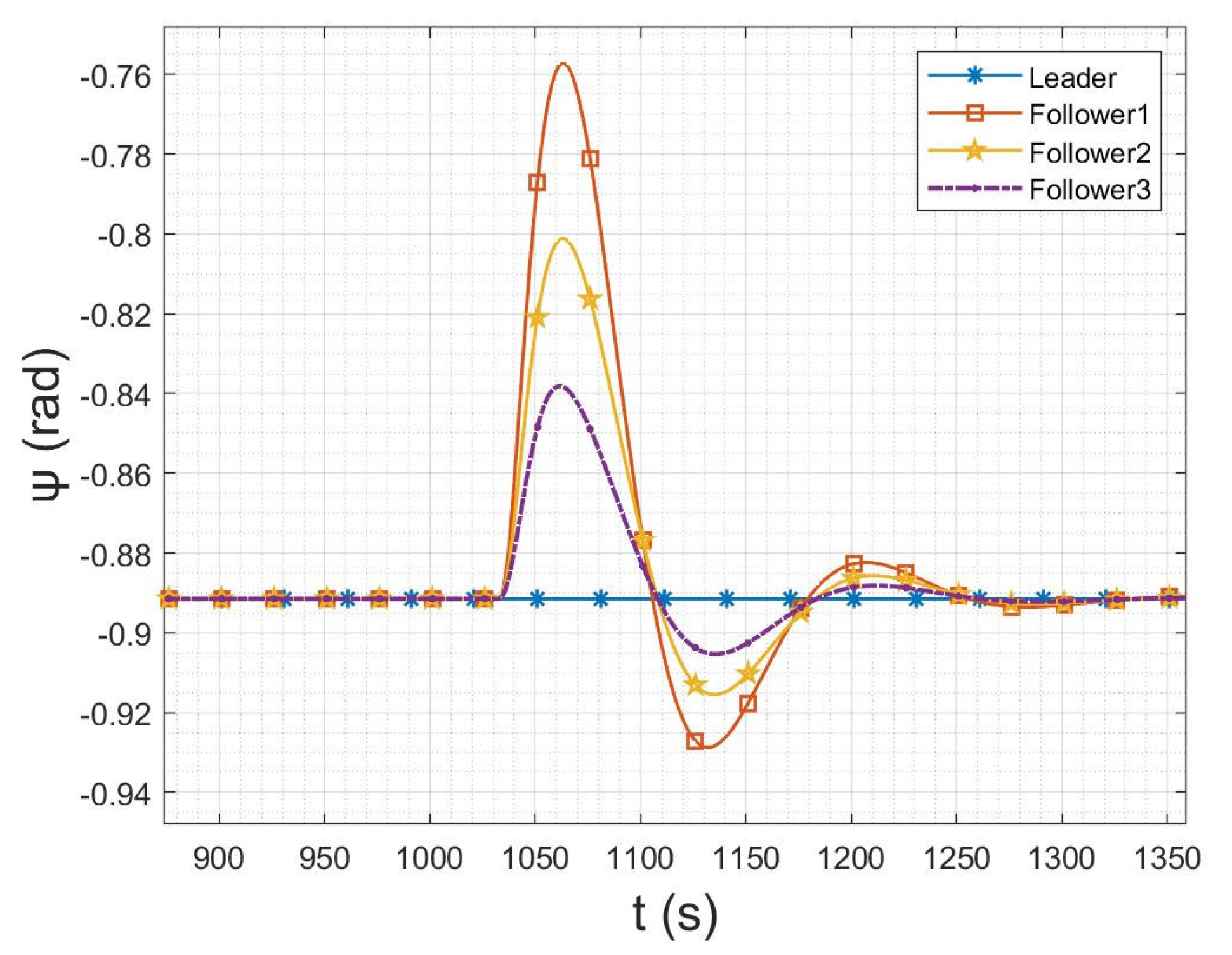
The formation transformation simulation also verifies the guidance law’s response characteristics to changes regarding the guidance target. The most important parameter to change is the heading angle. In this semiphysical simulation, the lead plane and the wingmen kept the same heading and flew parallel in the triangular formation. The formation management module generated a new path tracking point after receiving the formation change command, and the wingman guidance law guided the UAVs to the unique path tracking point, which mainly produced changes in the heading angle. Having completed the formation change, the lead plane and the wingmen flew in the new stepped formation and kept the same heading while flying in parallel. Figure 23 shows the evolution of heading angle in the formation change. As can be seen, the wingman heading angle changed rapidly after the command to change the formation, and the wingman heading converged quickly upon completion of the formation change.

6. Actual Flight Verification

6.1. Flight Platform and Ground Measurement and Control System

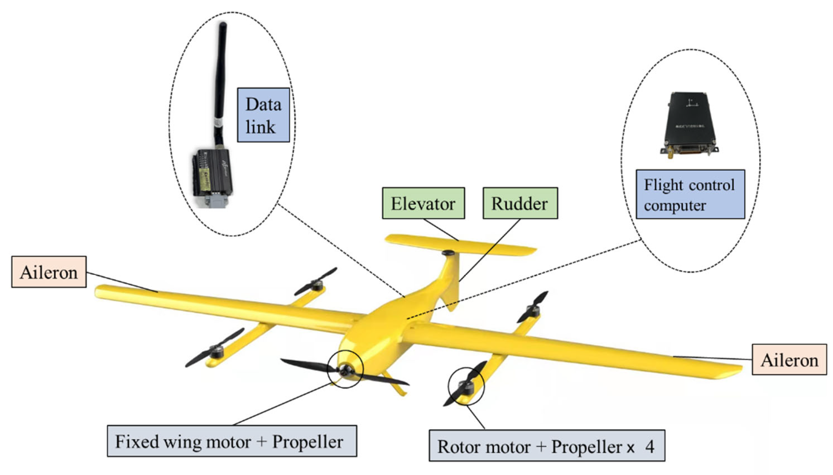
The UAVs used in the test are electric vertical takeoff and landing aircraft (eVTOL). The aircraft in this layout can takeoff and land vertically with the rotor, thereby extending the total flight time, which can fly in the air for a long time to verify the control method proposed in this paper. As shown in Figure 24, it adopts the layout of large wingspan and high flat tail. The wingspan is 2.2 m and the takeoff weight is 6 kg. The main parameters of the UAV are shown in Table 1.
As the best way to show the practicality of the designed control method, the actual flight test in the field was the final verification link of the fixed-wing UAV cooperative formation control method intended herein. The main equipment involved in the real flight test was the UAV flight platform and the ground measurement and control system, described separately below.
The UAV flight platform comprised two categories of equipment: (i) the flight-control system comprising the flight-control computer and the data-link radio and (ii) the actuating equipment, such as motors, electric speed controllers, and steering gears. The complete equipment of the flight platform is shown in Figure 25.
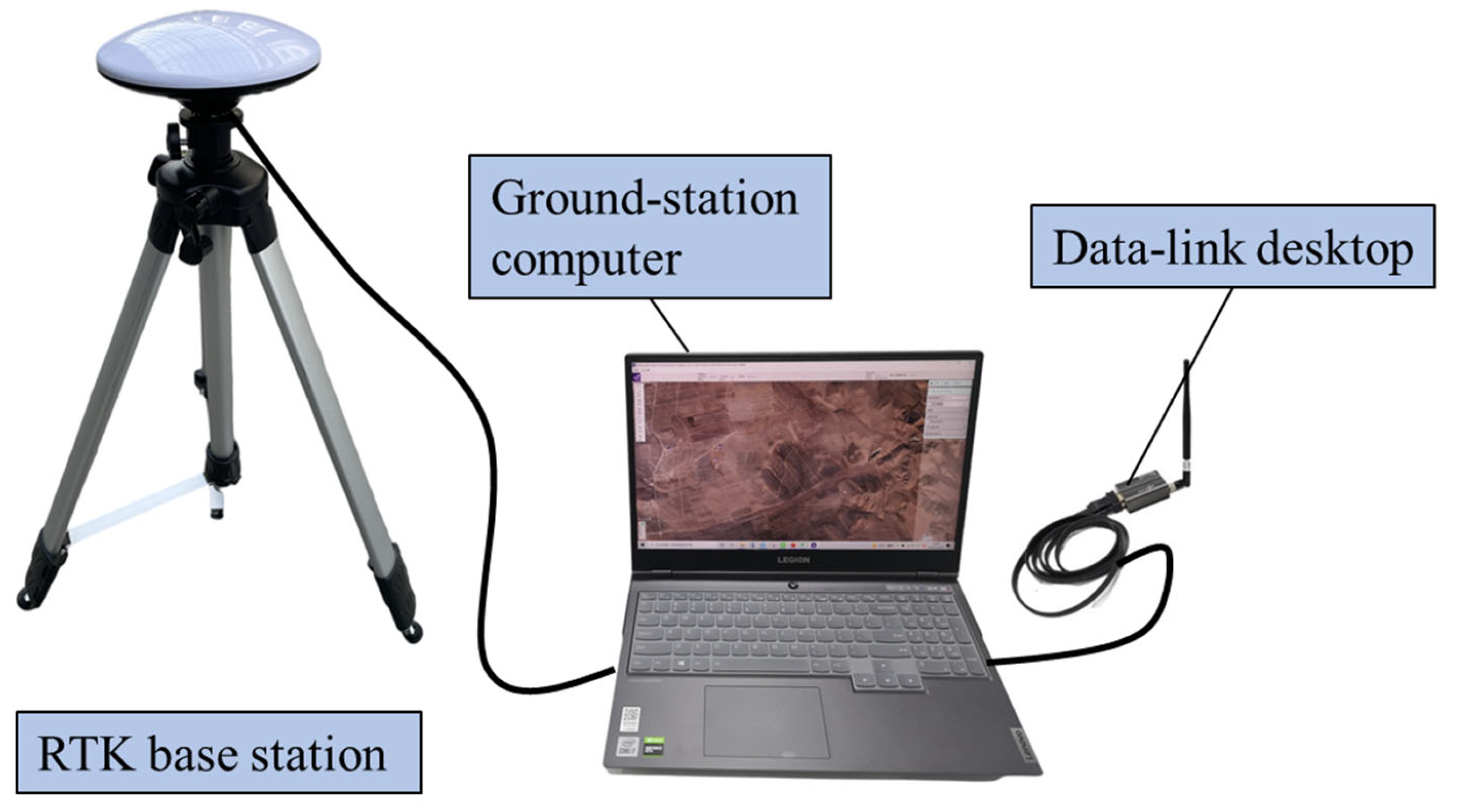
The main parts of the ground measurement and control system were the ground-station computer, the real-time kinematic (RTK) base station, and the data-link desktop terminal, as shown in Figure 26. Among these, the ground-station computer was the main equipment for remote control and telemetry between the ground station and the UAVs; it was responsible for checking the real-time status of the UAVs and sending control instructions. The RTK base station generated differential positioning data; coordinated formation flight requires high positioning accuracy. The differential data generated by the base station were transmitted to the flight-control computer through the data link to enable the drones to enter positioning mode with centimeter-level accuracy. The desktop end of the data link was a node of the data link, and this node was connected to the ground-station computer, securing the ground-station software to the entire communication link.
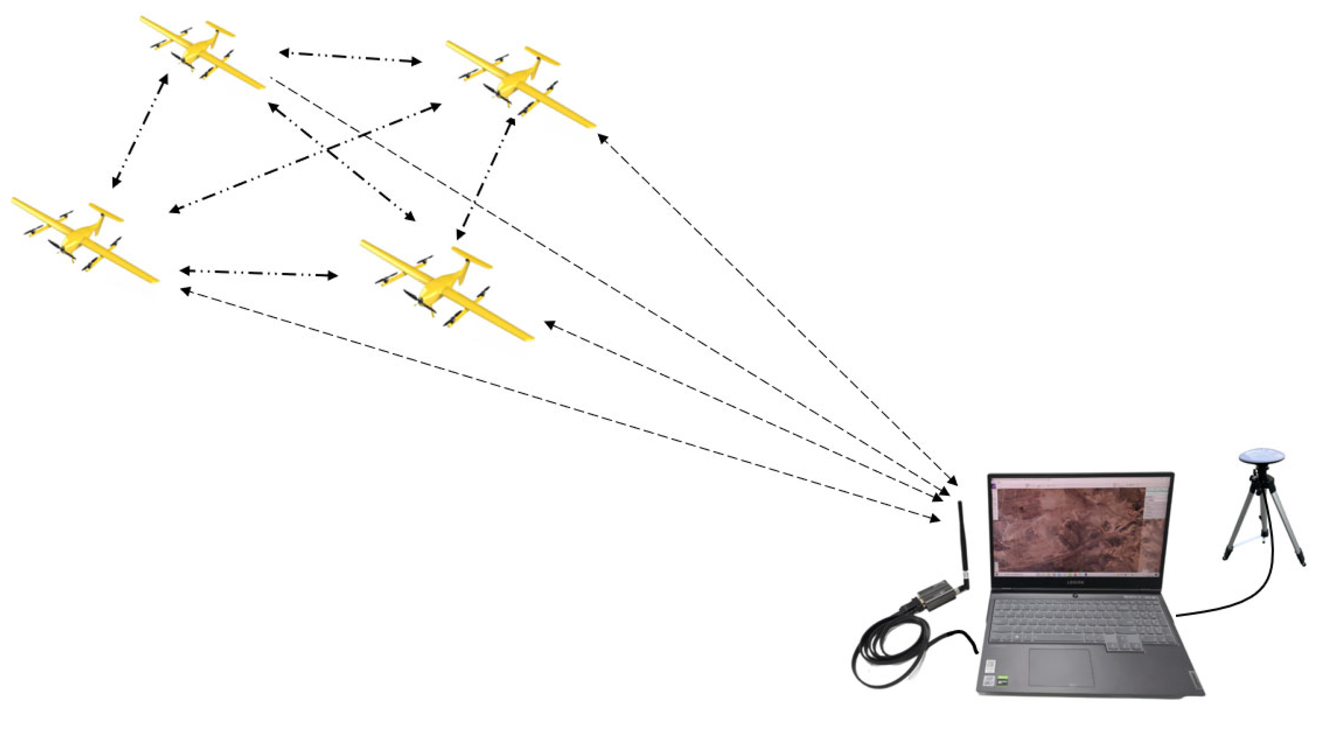
The UAV flight platform and the ground measurement and control system were the core equipment of the formation flight test. Figure 27 shows the equipment connection for the four-machine formation flight test, where a dotted line is a wireless connection between data links. The ground-station system monitored the status of each UAV flight platform in real-time during flight and also initiated some control commands, such as opening, changing, and closing the formation.

6.2. Formation Flight Test

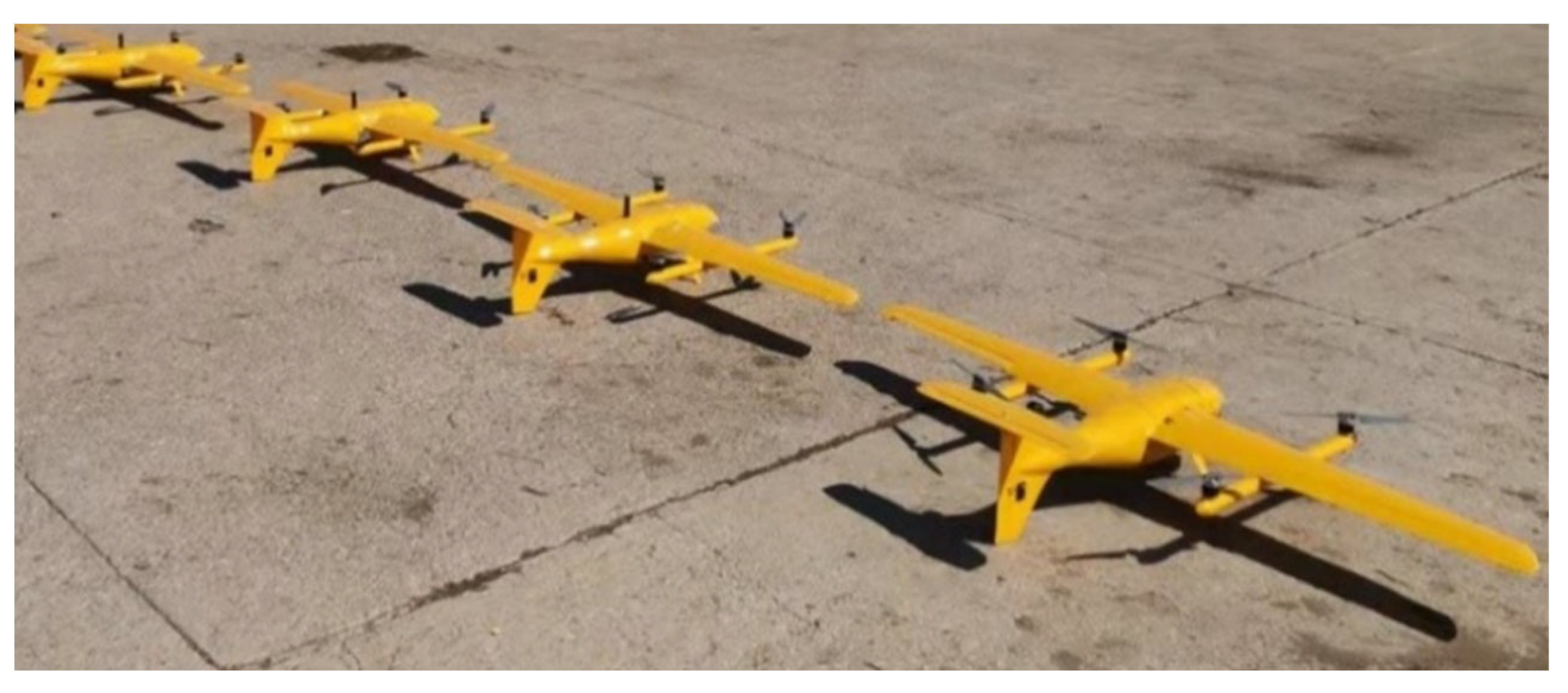
The outdoor flight test reported herein involved a four-aircraft formation. Figure 28 shows a photograph of the UAVs before takeoff.
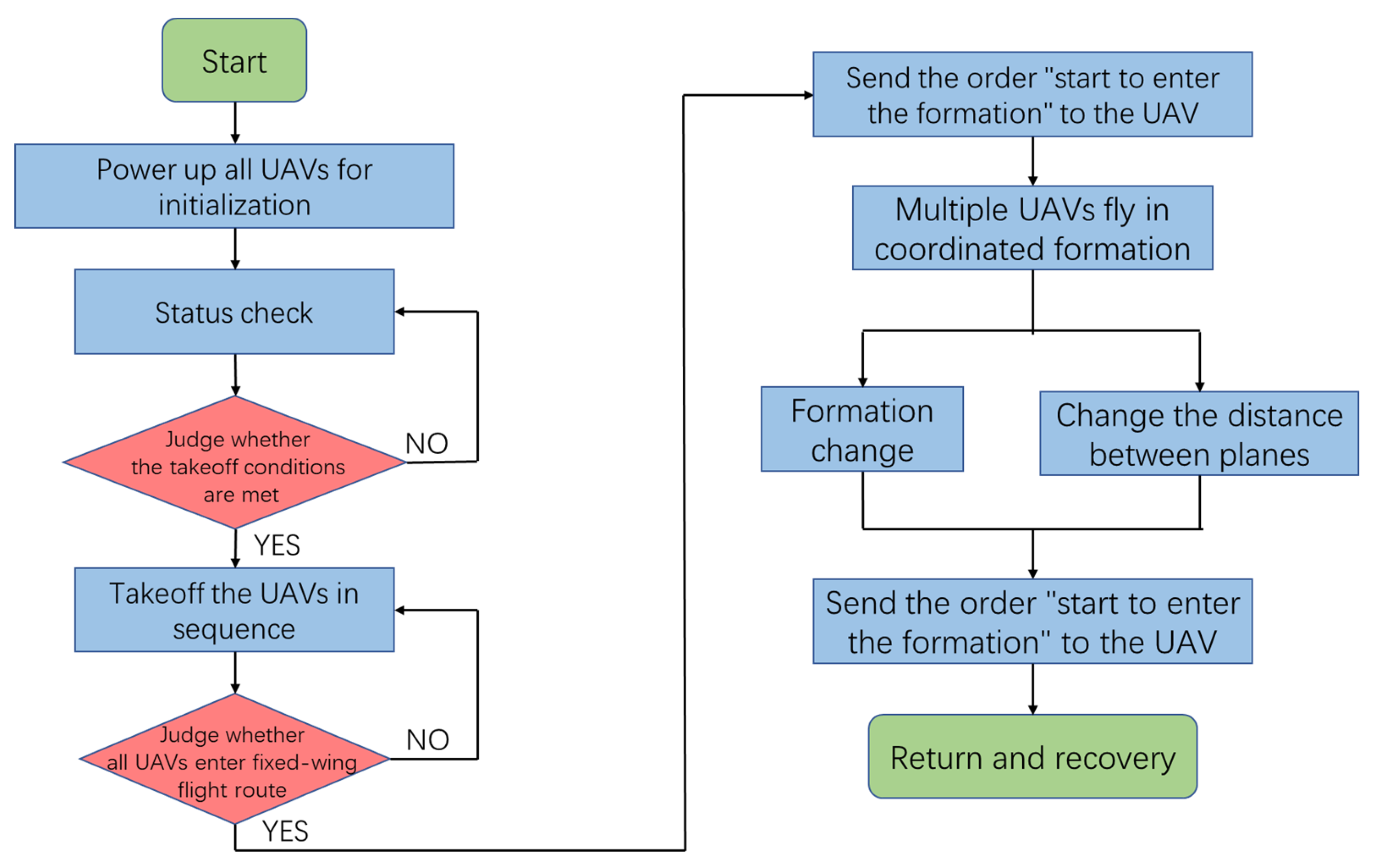
First, each UAV was placed at a fixed takeoff point and a power-on operation was performed. After the flight-control computer system was initialized, the ground station began to detect the states of the UAVs. If any of the drones did not meet the takeoff status, the status of all the drones was rechecked until the takeoff conditions were met. Send the takeoff command, then all drones enter the fixed-wing mode, when all drones are flying to the right place. The station sends the “open formation” command, and the drones enter the cooperative formation flight mode. At this time, the command was sent to change the cooperative formation, and the flight modes of the wingmen in the tight formation were changed according to the flight requirements. After the formation test was completed, the ground station sent a “close formation” command, whereupon the leader and wingmen exited the coordinated formation mode, flew along their respective routes, and finally returned to their takeoff points for recovery (Figure 29).
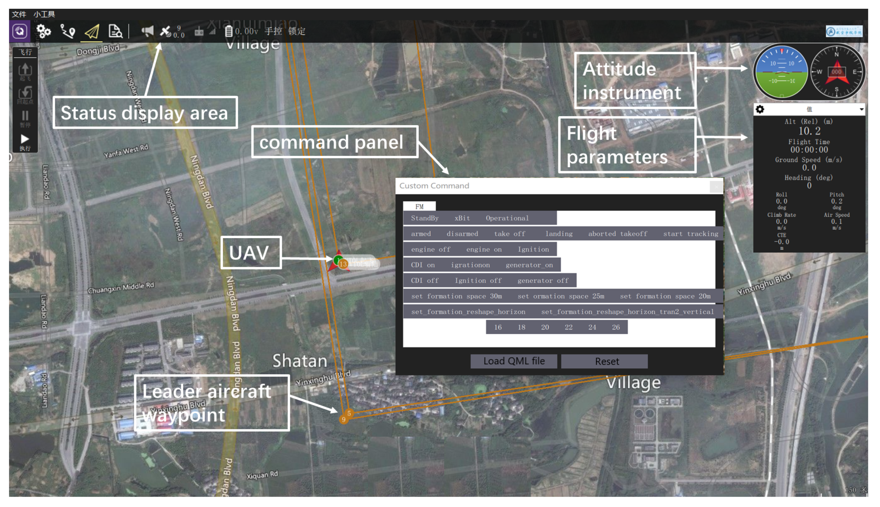
The ground-station software was connected to the communication links of the UAVs through the ground data-link node, and it was responsible for real-time communication with all the UAVs in the formation to (i) monitor their status during the flight, (ii) send the takeoff and landing instructions to each aircraft, and (iii) send the mission instructions, among other duties. The flight-control interface of the ground-station software is shown in Figure 30.
In the figure, the corresponding commands can be sent to the drone through the control panel. The status of the current drone can be seen in the attitude instrument and flight parameter information in the upper-right corner.
The command panel of the ground-station software was the main functional area for controlling the flight of the UAVs, including the command areas related to (i) single-aircraft takeoff and landing and (ii) formation. The instructions for single-aircraft takeoff and landing are to complete the takeoff and landing of a single UAV, including unlocking, locking, takeoff, and landing. The formation commands control the opening and closing of the formation mode and set the formation parameters after the UAVs entered the fixed-wing flight state; they included instructions such as turning the formation mode on and off and setting the formation shape and spacing parameters.
In this test, two types of coordinated formation flight were carried out, i.e., the stepped formation and the straight-line formation. The two formation arrangements were relatively simple but could also verify the control method of formation maintenance and change proposed herein. This outdoor flight began with a coordinated flight in a straight formation, and then the ground-station software issued the “set stepped formation” command, and the formation changed to a stepped formation and continued to fly. Figure 31 shows the actual outdoor flight conditions of the linear collaborative formation (Figure 31a) and the stepped collaborative formation (Figure 31b).
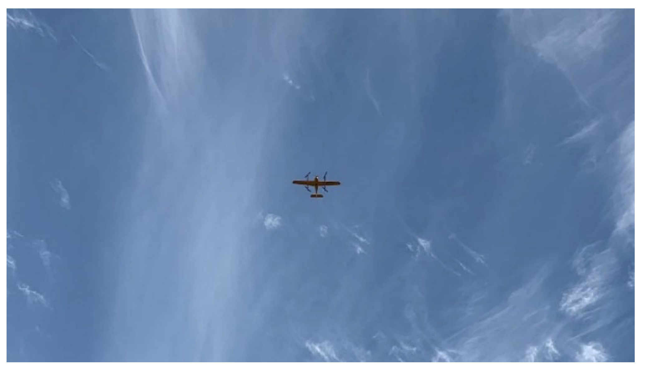
When it was necessary for the UAVs to return, the ground station sent the command to dissolve the formation, and all the UAVs participating in the formation exited the formation mode and automatically returned to the mission route of single-machine flight (Figure 32). Finally, the ground station sent the software command to return to the takeoff points and complete the return landing and recovery one by one.

6.3. Flight Data Analysis

Analyzing the flight outcome provides direct and effective data to support the results of the outdoor flight. After the outdoor flight test was completed, the track file recorded in the flight-control computer was imported for data analysis. The data were processed in different drawing and visualization software to analyze the flight results from other dimensions.
The direct indicator of the guidance-law effect in the data is the wingman heading angle’s tracking development after the guidance target change. Figure 33 shows the change curve of the heading angle of each UAV in the formation for times between 634 and 654 s in the track record file. As can be seen, when the heading angle of the leader changed, those of the wingmen responded and tracked it in time. Therefore, the response characteristics of the guidance law used herein are verified, and it is shown that the guidance-law algorithm can meet practical needs.
Furthermore, the flight trajectory of each UAV in the formation reflects intuitively the effect of cooperative formation from the data. Figure 34a shows the 3D trajectories of the actual flight route as plotted from the data for a stable formation section. The trajectories comprise the three geographical coordinates of longitude, latitude, and altitude; the horizontal coordinates are longitude and latitude, and the vertical coordinate is altitude. As can be seen, each UAV kept a fixed distance within the allowable error range, and the UAVs flew together. Figure 34b shows the entire formation trajectory, which intuitively reflects the flying effect of the trajectory in the real scene.
Within a certain allowable range of control error, this paper reports research on a cooperative formation control method for fixed-wing UAVs. The effect of the actual flight of the formation meets the design requirements and the requirements of formation control for some specific tasks.

7. Conclusions

The management of UAVs entering and departing from formation is an indispensable part of intelligent and information-based UAV operations. Aimed at the problem of maintaining a multi-UAV formation, reported herein was the design of a collaborative guidance law based on the classic missile-type parallel-approach method. According to (i) the flight mission characteristics of a lead aircraft following a route and wingmen following the lead aircraft and (ii) the general characteristics of the route, a guidance law was designed for three guidance modes: straight line, turning, and circling. The design of the entry and departure management of the formation led to strategies for the access and departure management of multi-machine independent assembly, dissolution, and special cases, thereby allowing effective management and control of the formation. An entry and departure adjustment strategy for special circumstances was given. The hardware-in-the-loop simulation and measured flight verification showed that the guidance law is practical in meeting UAV formation flight-control requirements for specific flight missions. Although it was tested on low-speed UAV platforms, it is still applicable to high-speed UAV platforms. Future work will focus the algorithm on high-speed platform validation.

Author Contributions

Conceptualization, G.Z. and Z.G.; methodology, G.Z.; software, G.Z. and Z.G.; validation, G.Z., Z.G. and Q.L.; formal analysis, Z.Z.; investigation, Z.Y.; resources, G.Z.; data curation, Z.W.; writing—original draft preparation, G.Z. and Z.Z.; writing—review and editing, Z.W. and Q.L.; visualization, D.Z.; supervision, Z.Y.; project administration, G.Z. All authors have read and agreed to the published version of the manuscript.

Funding

This research received no external funding.

Institutional Review Board Statement

Not applicable.

Informed Consent Statement

Not applicable.

Data Availability Statement

Data available on request due to restrictions eg privacy or ethical. The data presented in this study are available on request from the corresponding author. The data are not publicly available due to commercial use.

Conflicts of Interest

The authors declare no conflict of interest.

References

  1. Bian, L.; Sun, W.; Sun, T. Trajectory Following and Improved Differential Evolution Solution for Rapid Forming of UAV Formation. IEEE Access 2019, 7, 169599–169613. [Google Scholar] [CrossRef]
  2. Wang, G.; Luo, H.; Xiaohuan, H.; Huaiwei, M. A Survey on Coordinated UAV Formation Management. Electron. Opt. Control. 2013, 20, 48–53. [Google Scholar]
  3. Anderson, B.; Fidan, B.; Yu, C.; Walle, D. UAV Formation Control: Theory and Application. Lect. Notes Control. Inf. Sci. 2008, 371, 15–33. [Google Scholar]
  4. Zhang, J.; Yan, J. A Novel Control Approach for Flight-Stability of Fixed-Wing UAV Formation With Wind Field. IEEE Syst. J. 2020, 15, 2098–2108. [Google Scholar] [CrossRef]
  5. Kada, B.; Khalid, M.; Shaikh, M.S. Distributed cooperative control of autonomous multi-agent UAV systems using smooth control. J. Syst. Eng. Electron. 2020, 31, 1297–1307. [Google Scholar] [CrossRef]
  6. Wang, Y.; Yue, Y.; Shan, M.; He, L.; Wang, D. Formation Reconstruction and Trajectory Replanning for Multi-UAV Patrol. IEEE/ASME Trans. Mechatron. 2021, 26, 719–729. [Google Scholar] [CrossRef]
  7. Lee, M.-Y.; Chen, B.-S.; Tsai, C.-Y.; Hwang, C.-L. Stochastic H∞ Robust Decentralized Tracking Control of Large-Scale Team Formation UAV Network System With Time-Varying Delay and Packet Dropout Under Interconnected Couplings and Wiener Fluctuations. IEEE Access 2021, 9, 41976–41997. [Google Scholar] [CrossRef]
  8. Kebo, I.L.; Chen, L.; Bai, X.Z. Differential geometric modeling of guidance problem for interceptors. Sci. China Technol. Sci. 2011, 54, 13. [Google Scholar]
  9. Sun, S.; Zhou, D.; Hou, W.T. A guidance law with finite time convergence accounting for autopilot lag. Aerosp. Sci. Technol. 2013, 25, 132–137. [Google Scholar] [CrossRef]
  10. Wang, Y.; Shan, M.; Wang, D. Motion Capability Analysis for Multiple Fixed-Wing UAV Formations With Speed and Heading Rate Constraints. IEEE Trans. Control. Netw. Syst. 2019, 7, 977–989. [Google Scholar] [CrossRef]
  11. Zhang, J.; Yan, J.; Zhang, P. Multi-UAV Formation Control Based on a Novel Back-Stepping Approach. IEEE Trans. Veh. Technol. 2020, 69, 2437–2448. [Google Scholar] [CrossRef]
  12. Dong, X.; Yu, B.; Shi, Z.; Zhong, Y. Time-Varying Formation Control for Unmanned Aerial Vehicles: Theories and Applications. IEEE Trans. Control. Syst. Technol. 2014, 23, 340–348. [Google Scholar] [CrossRef]
  13. Yang, J.; Wang, X.; Baldi, S.; Singh, S.; Fari, S. A software-in-the-loop implementation of adaptive formation control for fixed-wing UAVs. IEEE/CAA J. Autom. Sin. 2019, 6, 1230–1239. [Google Scholar] [CrossRef]
  14. Gomez, M.B.; Gomez, B.M. Hardware-in-the-Loop Simulation. Transp. Res. Part C Emerg. Technol. 2001, 12, 73–89. [Google Scholar]
  15. Ren, W.; Steurer, M.; Baldwin, T.L. Improve the Stability and the Accuracy of Power Hardware-in-the-Loop Simulation by Selecting Appropriate Interface Algorithms. In Proceedings of the Industrial & Commercial Power Systems Technical Conference IEEE, Edmonton, AB, Canada, 6–11 May 2007. [Google Scholar]
  16. Duan, H.; Qiu, H. Unmanned Aerial Vehicle Distributed Formation Rotation Control Inspired by Leader-Follower Reciprocation of Migrant Birds. IEEE Access 2018, 6, 23431–23443. [Google Scholar] [CrossRef]
  17. Chang, L.B.; Ng, Q.S. A flexible virtual structure formation keeping control for fixed-wing UAVs. In Proceedings of the IEEE International Conference on Control & Automation IEEE, Santiago, Chile, 19–21 December 2011. [Google Scholar]
  18. Li, N.H.; Liu, H.H. Formation UAV flight control using virtual structure and motion synchronization. In Proceedings of the American Control Conference IEEE, Seattle, WA, USA, 11–13 June 2008. [Google Scholar]
  19. Tanner, G.H.; Pappas, G.J.; Kumar, V. Leader-to-Formation Stability. IEEE Trans. Robot. Autom. 2004, 20, 443–455. [Google Scholar] [CrossRef] [Green Version]
  20. Stipanovic, D.M.; Inalhan, G.; Teo, R.; Tomlin, C.J. Decentralized overlapping control of a formation of unmanned aerial vehicles. In Proceedings of the IEEE Conference on Decision & Control IEEE, Maui, HI, USA,, 9–12 December 2003. [Google Scholar]
  21. Vignoni, A.; Garrelli, F.; García-Nieto, S.; Picó, J. UAV Reference Conditioning for Formation Control Via Set Invariance and Sliding Modes. IFAC Proceeding Vol. 2012, 45, 317–322. [Google Scholar] [CrossRef]
  22. Liao, F.; Teo, R.; Wang, J.L.; Dong, X.; Lin, F.; Peng, K. Distributed Formation and Reconfiguration Control of VTOL UAVs. IEEE Trans. Control. Syst. Technol. 2017, 25, 270–277. [Google Scholar] [CrossRef]
  23. Wei, L. Distributed UAV formation control using differential game approach. Aerosp. Technol. 2014, 35, 54–62. [Google Scholar]
  24. Liu, C. Multiple UAV formation control based on consensus control structure. J. Huazhong Univ. Sci. Technol. 2015, 43, 481–485. [Google Scholar]
  25. Gosiewski, Z.; Ambroziak, L. UAV Autonomous Formation Flight Experiment with Virtual Leader Control Structure. Solid State Phenom. 2013, 198, 254–259. [Google Scholar] [CrossRef]
  26. Shen, D.B.; Sun, Z.; Sun, W. Leader-follower formation control without leader’s velocity information. Sci. China Inform. Sci. 2014, 57, 1–12. [Google Scholar] [CrossRef] [Green Version]
  27. Shi-Cai, L.I.U.; Da-Long, T.A.N.; Guang-Jun, L.I.U. Robust Leader-follower Formation Control of Mobile Robots Based on a Second Order Kinematics Model. Acta Autom. Sin. 2007, 33, 947–955. [Google Scholar]
  28. Guo, D.; Wang, H.; Weidong, C. Image-based Leader-Follower Formation Control of Mobile Robots with Uncalibrated On-board Camera. In Proceedings of the IEEE International Conference on Robotics and Automation, Seattle, DC, USA, 26–30 May 2015. [Google Scholar]
  29. Ajorlou, A.; Moezzi, K.; Aghdam, A.G.; Nersesov, S.G. Two-stage time-optimal formation reconfiguration strategy. Automatica 2013, 62, 496–502. [Google Scholar] [CrossRef] [Green Version]
  30. Wang, J.; Zhang, J.; Cao, X.; Wang, F. Optimal satellite formation reconfiguration strategy based on relative orbital elements. Acta Astronaut. 2012, 76, 99–114. [Google Scholar] [CrossRef]
Figure 1. Formation control framework based on cooperative waypoint-following.
Drones 06 00099 g001
Figure 2. Schematic for calculating the virtual dynamic tracking point.
Drones 06 00099 g002
Figure 3. Schematic of guidance by parallel-approach method.
Drones 06 00099 g003
Figure 4. Relationship between wingman and dynamic tracking point.
Drones 06 00099 g004
Figure 5. Attitude control modeling of lateral-heading channel.
Drones 06 00099 g005
Figure 6. Attitude control modeling of pitch channel.
Drones 06 00099 g006
Figure 7. Control modeling of velocity channel.
Drones 06 00099 g007
Figure 8. Tracking effect of wingman: (a) time histories of the heading angle; (b) time histories of the velocities.
Drones 06 00099 g008
Figure 9. Schematic of linear formation for collaborative waypoint management.
Drones 06 00099 g009
Figure 10. Relationship of coordinated waypoints in straight horizontal formation.
Drones 06 00099 g010
Figure 11. Relationship of cooperating waypoints in horizontal triangular formation.
Drones 06 00099 g011
Figure 12. Plan view of relationship among coordination waypoints for stepped formation.
Drones 06 00099 g012
Figure 13. Side view of relationship among coordination waypoints for stepped formation.
Drones 06 00099 g013
Figure 14. Schematic of formation transformation process.
Drones 06 00099 g014
Figure 15. Example of formation change process.
Drones 06 00099 g015
Figure 16. Data-link survivable network architecture.
Drones 06 00099 g016
Figure 17. Schematic of formation reconstruction.
Drones 06 00099 g017
Figure 18. Relationship among all systems in hardware-in-the-loop simulation.
Drones 06 00099 g018
Figure 19. Device connection diagram for hardware-in-the-loop simulation.
Drones 06 00099 g019
Figure 20. Hardware-in-the-loop simulation: (a) ground-station perspective; (b) Tacview software perspective.
Drones 06 00099 g020
Figure 21. Three-dimensional view of hardware-in-the-loop simulation of formation transformation: (a) triangular formation; (b) formation in the middle of changing; (c) stepped formation.
Drones 06 00099 g021
Figure 22. Changes of positions of wingmen relative to leader in formation change.
Drones 06 00099 g022
Figure 23. Change in heading angle during formation transformation.
Drones 06 00099 g023
Figure 24. Electric vertical takeoff and landing aircraft.
Drones 06 00099 g024
Figure 25. UAV flight platform equipment.
Drones 06 00099 g025
Figure 26. Connections of ground measurement and control system.
Drones 06 00099 g026
Figure 27. Connections of formation test equipment.
Drones 06 00099 g027
Figure 28. Photograph of four-plane coordinated formation before takeoff.
Drones 06 00099 g028
Figure 29. Flow chart of formation flight test.
Drones 06 00099 g029
Figure 30. Flight interface of ground-station software.
Drones 06 00099 g030
Figure 31. Photographs of actual flight of four-machine coordinated formation: (a) ground view of straight formation; (b) aerial view of stepped formation.
Drones 06 00099 g031
Figure 32. UAV returning after leaving formation.
Drones 06 00099 g032
Figure 33. Control effect of actual flight-heading channels of four aircraft in cooperative formation.
Drones 06 00099 g033
Figure 34. Three-dimensional maps of actual flight route of four-plane cooperative formation: (a) trajectory diagram from plotting software; (b) flight trajectory.
Drones 06 00099 g034
Table 1. The main parameters of the UAV.
ItemParameter
Mass (kg)6.0
Reference   area   ( m 2 )0.46
Reference   span   ( m )2.2
Cruising   speed   ( m / s )20
Maximum   airspeed   ( m / s )23
Minimum   airspeed   ( m / s )17
Publisher’s Note: MDPI stays neutral with regard to jurisdictional claims in published maps and institutional affiliations.