3.1. Platform Characterization
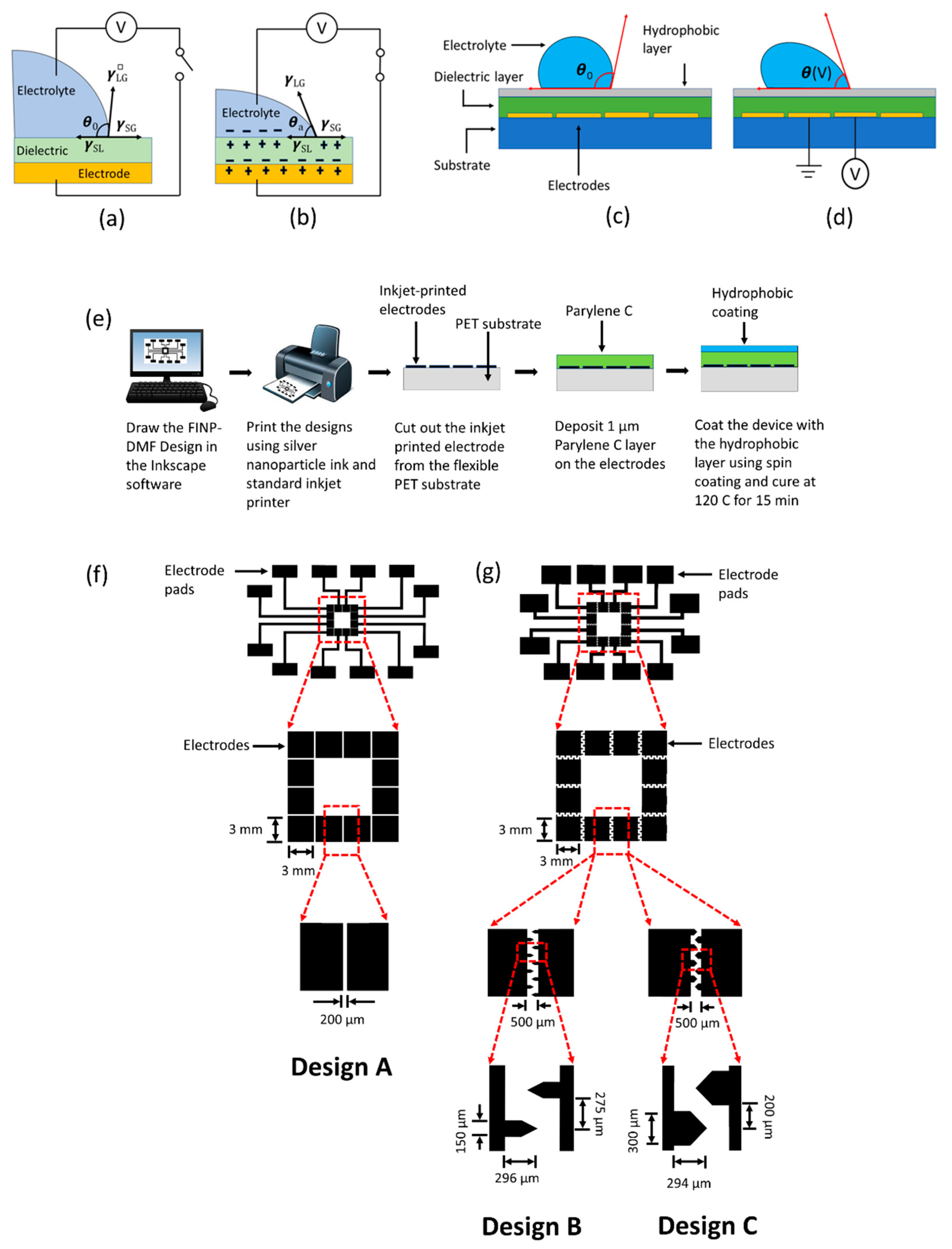
Miniaturized platforms based on EWOD-DMF for biochemical assays should operate with fast droplet response times, minimum sample volumes, low power supply and a range of different sample solutions. These platforms require many considerations to generate a system that is dependable, inexpensive, easily manufacturable and generates accurate results in short periods. These considerations include proper electrode design and fabrication, suitable working parameters, the ability to handle a wide range of physiological relevant reagents and compositions. For this purpose, we showed the easy and cost-effective printing of conductive ink-based electrode arrays onto flexible substrates (
Figure 1e). These inkjet-printed electrode patterns were generated within minutes using commercially available printers, eliminating the need for sophisticated equipment. Due to the importance of electrode design in droplet moving efficiency, two types of electrode configurations were tested. The first was a square electrode configuration (electrode design A) and the second was an interdigitated electrode configuration (electrode design B and electrode design C, respectively). Square and interdigitated electrode designs have been widely used in many existing EWOD studies [
19,
20]. Design A (
Figure 1f) contains an array of square-shaped electrodes each 3 mm × 3 mm in size with a gap of 200 μm between two adjacent electrodes. The interdigitated electrode configuration (design B and C,
Figure 1g) contains an array of electrodes with a base size of 3 mm × 3 mm with saw-tooth-like interdigitated features that are 150 μm in width for design B and 300 μm in width for design C. The detailed dimensions are shown in
Figure 1g. The height of the electrodes was found to be approximately 300 nm. Additionally, the resistivity and conductivity of the electrodes was measured as approximately 1.6 × 10
−7 Ω·m and approximately 6.25 × 10
6 S/m, respectively. The sheet resistance was measured as approximately 0.5 Ω/sq. Here, we first performed initial characterization experiments to find the appropriate working parameters and electrode design (voltage, droplet volume, different fluids) for the rapid as well as effective manipulation and mixing of droplet suspensions followed by performing more clinically relevant experiments. Initial experiments were performed by optimizing the sample droplet volume. To move droplets continuously without any interruption on an array of electrodes, it is essential to use a droplet volume that not only covers the electrode directly beneath the droplet but also partially covers the adjacent electrodes. For the characterization of this work, we used three commonly used buffers in cell biological assays: DI water (buffer I), 1X phosphate-buffered saline (PBS, buffer II), and 5X PBS (buffer III). For these initial characterization experiments discussed within this section, buffer I was utilized. For all the experiments, droplets were placed on the FINP-DMF platform using laboratory pipettes. Droplet volumes of 20, 30 and 40 μL of buffer I were actuated within printed electrode arrays. It was found that 20 μL droplets failed to cover adjacent electrodes, interrupting their motion on the electrode arrays whereas 30 and 40 μL droplets were able to slightly overlap adjacent electrodes resulting in uninterrupted motion. To minimize the sample volume, which is one of the major requirements in most miniaturized platforms, we chose to work with 30 μL droplets for all the experiments described herein.
In addition, for most EWOD-DMF devices (e.g., POC-based EWOD-DMF devices), it is essential to have a system that is both effective and efficient, one that can generate quick droplet motion with ideally minimum power consumption. To find the optimum driving force for droplet movement in our platform, five operating voltages were tested at 30, 45, 60, 75 and 90 V. At the lowest actuation voltage of 30 V, no droplet motion was observed, while at the highest voltage of 90 V, dielectric breakdown and hydrolysis was observed. However, proper actuation of droplets without dielectric breakdown or hydrolysis was achieved at 45, 60 and 75 V. The effect of actuation voltage on the droplet contact angle also plays an important role in droplet movement, as it has been shown that larger differences between actuated and non-actuated droplet contact angles generate larger electrowetting forces which yield a faster droplet movement [
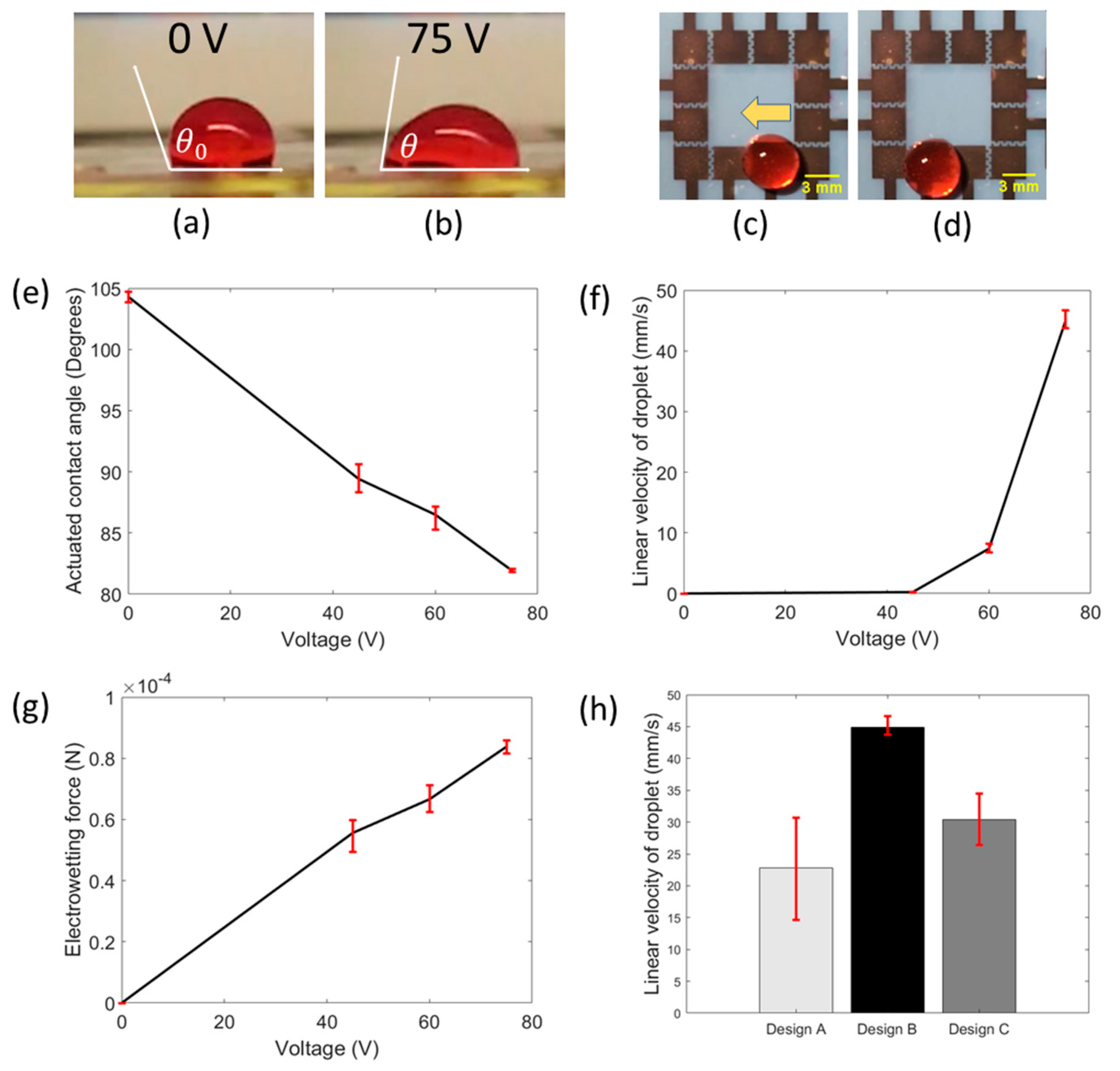
21]. According to the Young–Lippmann equation, the contact angle of the droplet upon actuation decreases with increasing actuation voltage. We experimentally investigated and verified this trend, as shown in
Figure 2e. Droplet motion was recorded using a smartphone camera and its contact angle, upon actuation, was measured using imageJ, an open-source image analysis software. This experiment was repeated for three devices for each value of actuation voltage. According to our results, when no voltage was applied, the average contact angle of the droplet was 104.3° (non-actuated contact angle) and for 45 V, the average contact angle decreased to 89.4°. Similarly, on the application of 60 V and 75 V, the average contact angles were found to be 86.4° and 81.9°, respectively. The error bars shown in
Figure 2e represent the maximum and minimum values of contact angle measurements obtained at each of the actuation voltages. In addition, it is important to maximize sample processing speed in our platform. We investigated the effect of different actuation voltages on the droplet velocity to find the proper voltage for the expeditious movement of droplets.
Figure 2c,d show the movement of a droplet under the influence of actuation voltages. Three devices were tested. The measured average velocities of droplets were found to be 0.23, 7.4 and 44.9 mm/s at actuation voltages of 45, 60 and 75 V, respectively (
Figure 2f). Error bars denote the maximum and minimum values of measured velocities at each actuation voltage. The resemblance of a parabolic curve (
Figure 2f) was observed for the relationship between droplet velocity and actuation voltage, which agrees with previously reported work [
21], where it was shown that the linear droplet velocity varies with the square of the actuation voltage [
21]. Furthermore, the electrowetting force was calculated for all three functional actuation voltages (45, 60 and 75 V) as shown in
Figure 2g. The electrowetting force was calculated to be greater with increasing actuation voltage, where at 45 V, the force was found to be 55 μN. At 60 V and 75 V, the force was found to be 66 μN and 84 μN, respectively. The increase in electrowetting force with respect to actuation voltage explains the increasing trend of linear droplet velocity. As the maximum droplet velocity and electrowetting driving force were observed at 75 V, this voltage was selected as the optimum value to carry out all the experiments and ensure rapid droplet response and faster biochemical assays. For all further experiments, we used an actuation voltage of 75 V.
Additionally, the high throughput capabilities of biochemical assays in EWOD-DMF devices is crucial for practical and clinical applications. It is important to appropriately consider electrode designs that produce controlled and rapid droplet movement so that numerous assay reactions and results can be attained quickly. Considering that, we initially studied the effect of different electrode configurations on linear droplet velocity. To determine the best geometry for maximum droplet speed and efficient manipulation, different high throughput electrode designs capable of providing high droplet velocity were designed and tested (A, B and C,
Figure 1f,g). For these experiments, droplets were placed on one electrode and actuated to the neighboring electrode. The droplet motion was recorded using a smartphone camera. Using image analysis, the linear droplet velocity was extrapolated by dividing the distance that the droplet traveled (length of the electrode plus gap) by the time required for the droplet to move from one electrode to another.
Figure 2h shows the bar plot of the linear droplet velocity of all three electrode designs. It shows that the droplet velocity was highest for design B (44.87 mm/s), followed by design C (30.43 mm/s), and lastly, design A (22.85 mm/s). For interdigitated electrode designs, such as B and C, it has been previously observed that linear droplet velocity is higher than that on the square electrodes. Our observations are consistent with this previously observed phenomenon [
22]. A higher velocity on interdigitated electrode configurations (B and C) compared to square electrode configuration (A) is attributed to increased length of the contact line between the droplet and the actuated electrode, which in turn generates an increase in the driving force [
22]. The difference between linear droplet velocities on design B and C can be explained by the fact that both designs have slightly different electrode designs (B has five and four fingers on opposing electrode pair; C has four and four fingers on opposing electrode pair) and thus, the increased length of the contact line of B, lends to a higher droplet velocity. As higher droplet velocities were observed on interdigitated electrode configurations (designs B and C), we chose to work with these designs for our further experiments.
Additionally, for biochemical assays performed on EWOD-DMF devices, droplets of different reagents are often dispensed from different sites on the device, moved towards each other, and made to coalesce to mix both the reagents. For example, Ng et al. reported a proof-of-concept EWOD-DMF platform for performing a rubella virus (RV) IgG immunoassay [
23]. RV IgG antibodies were detected using an indirect ELISA involving several droplets mixing steps to capture the IgG antibody and incorporate chemiluminescent labels to the sample. Droplet mixing is thus a fundamental operation that needs to be performed on EWOD-DMF devices to make them suitable for point-of-care biochemical assays and diagnostic tests, for instance. To characterize the mixing of two droplets on our FINP-DMF platform, we performed proof-of-concept experiments with droplets colored with different dyes and mixed them using the FINP-DMF platform, where the distinct color droplets served as models for different reagents. We initially investigated the effect of electrode geometry on droplet mixing by performing mixing experiments with the square electrode configuration (design A, shown in
Figure 1f) and an interdigitated electrode configuration (design C, shown in
Figure 1g).
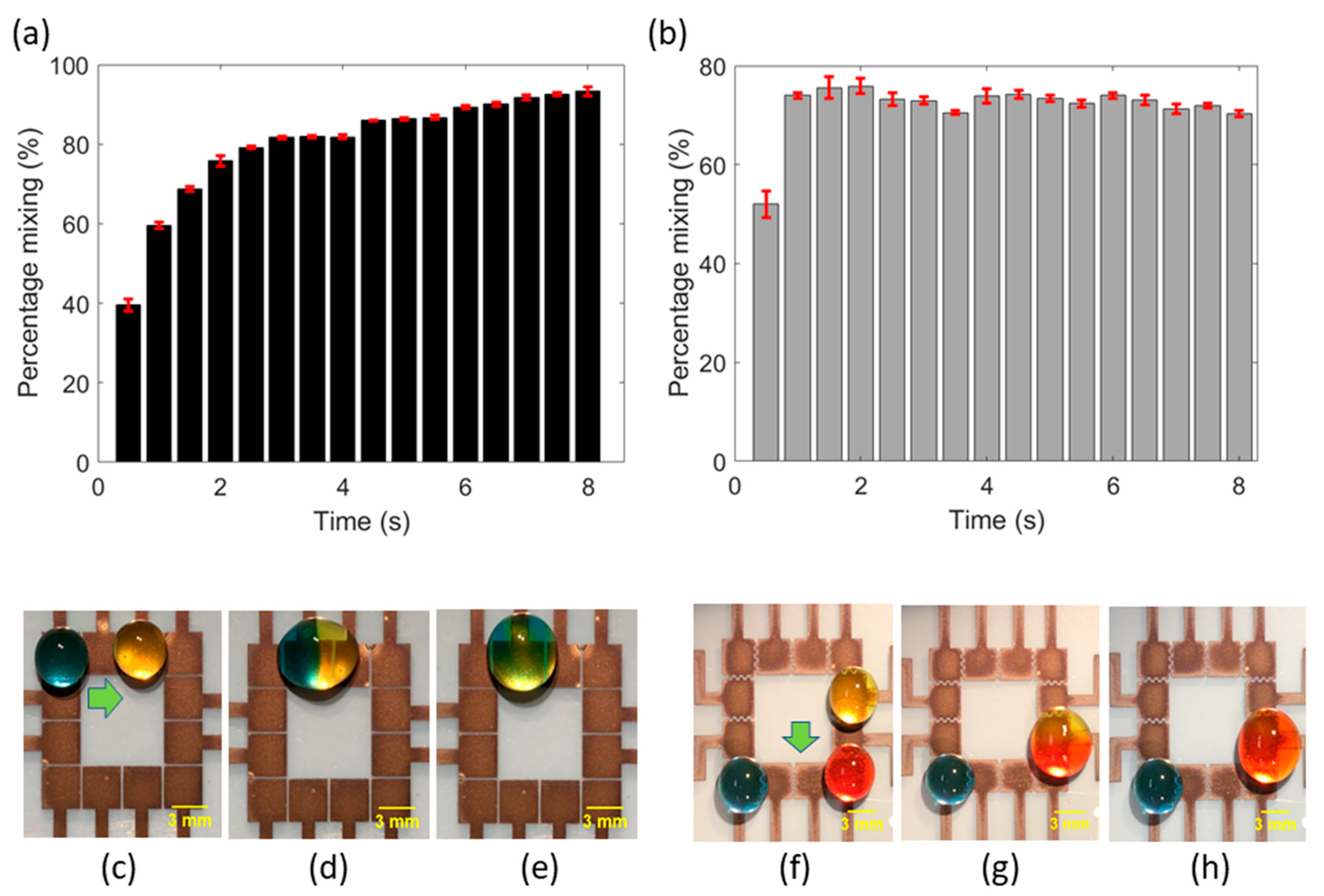
Figure 3c–e show the mixing of blue and yellow droplets on a square electrode configuration (design A), and
Figure 3f–h show the mixing of red and yellow droplets on the interdigitated electrode configuration (design C), under the actuation of 75 V. Moreover, the level and rate of mixing achieved is of equal importance in biochemical assays. EWOD-DMF devices must ensure that two droplets mix completely and homogeneously in short periods. Mixing of droplets is dominated by diffusion because of their laminar state, which is a slow process. It is therefore necessary to quantify the level and rate of mixing to meet the assay design objectives of complete reaction mixing rapidly. To characterize the rate of mixing in our FINP-DMF platform, we calculated the relative mixing index previously described in the literature [
21] for both design A and C. We performed image analysis using MATLAB and calculated the percentage of mixing (level of mixing) using the mathematical formula for RMI (defined in
Supplementary Information). A 12-megapixel smartphone digital camera at a rate of 30 frames/s and a tripod holder was used to fix the camera in place. A 150 W halogen variable intensity fiber optic light source was used for illuminating the device.
Figure 3a shows the graph of mixing percentage versus time for design A (
Figure 3c–e). It can be observed that mixing percentage rapidly increased with time within the first one or two seconds and remained almost constant thereafter. The rate of mixing at any given time can be found by calculating the slope of the curve at that time point. The maximum slope was observed between 0 s to 1 s, and the rate of mixing (slope) within this time interval was found to be 60%/s. A similar trend was observed for mixing on electrode design C (
Figure 3f–h), where the percentage mixing increased rapidly within the first second and then remained almost constant for the rest of the time duration (
Figure 3b). The maximum slope (rate of mixing) was observed in 0 s to 1 s and was calculated to be 78%/s. The higher slope of the curve (rate of mixing) for design C, compared to design A, may be attributed to higher linear droplet velocity on interdigitated electrode configuration, which enhances the natural oscillations of the droplet during its coalescence, resulting in rapid diffusion and mixing. To improve the mixing percentage, other methods such as moving the droplet rapidly back and forth or agitating the droplet with acoustic waves, could be employed.
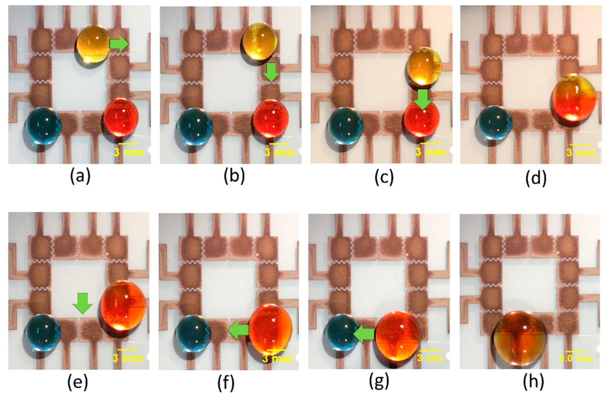
Having studied the effect of different parameters on moving and mixing of droplets, we moved on to demonstrate the utility of our platform to perform integrated droplet movement and sequential mixing operations. A 30 μL yellow droplet was initially placed on the top right corner, and a blue and a red-colored droplet were placed on the bottom left and right corner, respectively. While keeping the red droplet stationary, the yellow droplet was manipulated by applying the actuation voltage to the adjacent upper electrodes and grounding the electrode on which the droplet currently resides. By sequentially applying voltages in this way, we could move the yellow droplet. The yellow droplet was moved from the top right corner towards the bottom right corner, where it was mixed with the red colored droplet. This resultant droplet mixture was then moved towards the bottom left corner, where it was mixed with a blue-colored droplet.
Figure 4a–h show time sequence images of simultaneous movement and mixing using design C of the FINP-DMF platform. These experiments demonstrated the capability of our FINP-DMF platform to manipulate multiple droplets and perform different mixing and movement operations, which is often required in digital biochemical assays.
3.2. Platform Characterization for Clinically Relevant Reagents
Next, we tested the functionality of our FINP-DMF platform to work with pseudo biospecimen regents. Several biochemical assays are performed with a range of conductive media, such as phosphate saline buffer, lysis buffer and ethylene diamine tetra acetic acid (EDTA). As a result, EWOD-DMF devices utilized in biochemical assays for POC applications must be robust and operate with a range of reagents. To demonstrate the utility of our platform with such physiological conductive buffers, we performed experiments with a variety of liquids commonly used in biochemical assays, including buffer I (DI water), buffer II (1X PBS) and buffer III (5X PBS) solutions. Specifically, we quantified the linear droplet velocity of both these buffers at different actuation voltages, with the main aim of investigating the effect of buffer conductivity on droplet velocity.
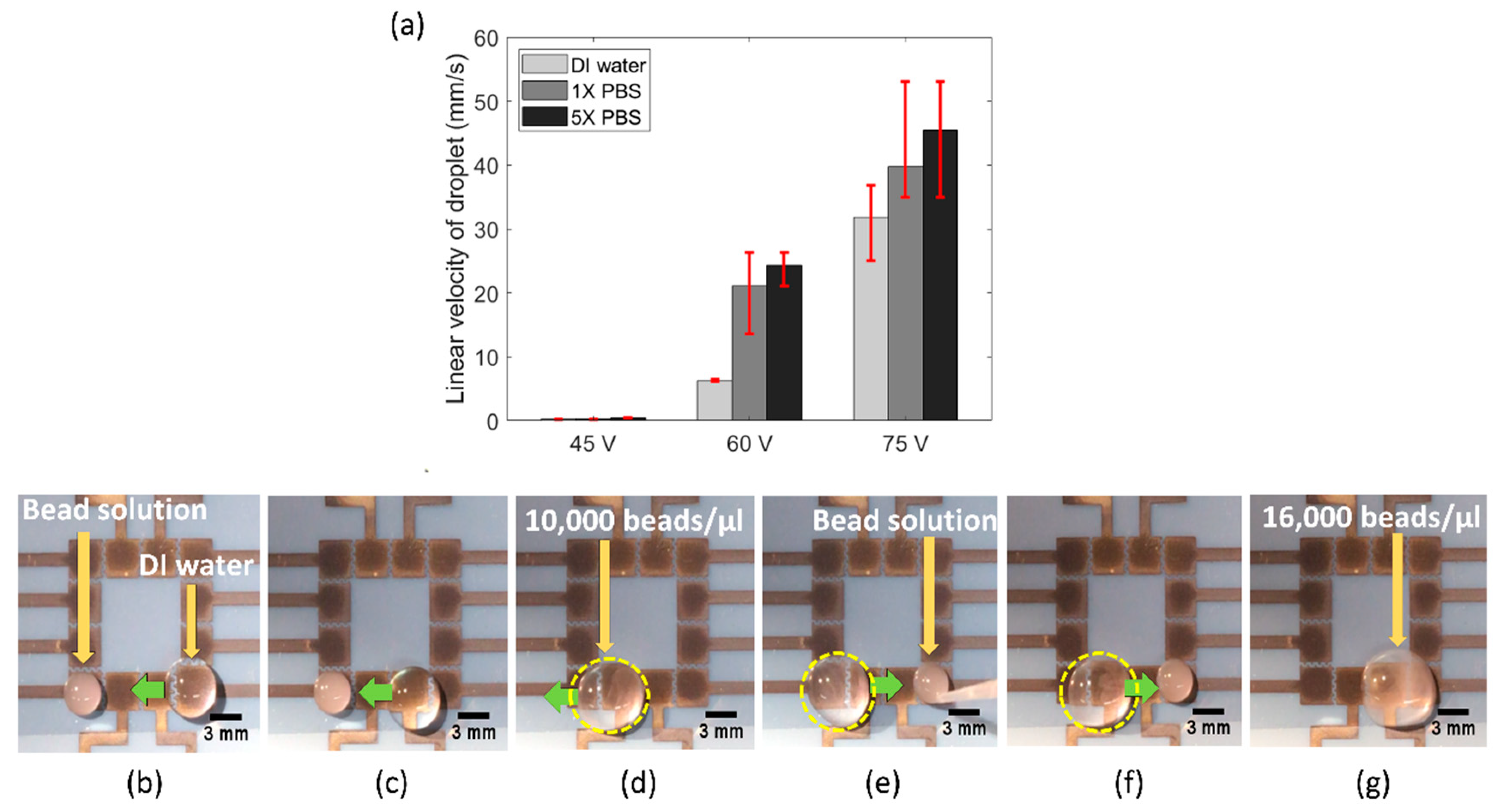
Figure 5a shows the bar plot of linear droplet velocity of buffer I (conductivity approximately 0.055 μS/cm), buffer II (conductivity approximately 15 mS/cm) and buffer III (conductivity approximately 75 mS/cm), at three different actuation voltages. It was observed that at any given actuation voltage, the linear droplet velocity was highest for buffer III, followed by buffer II and buffer I. It has been previously observed that the electrowetting force increases with liquid conductivity [
24]. Though the physics is still not well developed, it is theorized that higher conductivity liquids provide more charge to be produced at the solid–liquid interface and results in reduced surface tension. This is likely the reason why we observed the highest droplet velocity for buffer III and lowest droplet velocity for buffer I.
Biochemical assays often require manipulation, mixing and dilution of biological specimen samples, such as cell or DNA samples diluted with lysing buffer. Hence, we also examined the utility of our FINP-DMF device to manipulate and mix pseudo biospecimen suspensions and reagent and generate diluted suspensions. To do this, we manipulated a concentrated solution of 10 μm polystyrene (PS) beads (SPI supplies, USA) sample, where beads were used as models of cells. We placed a 10 μL droplet of a concentrated (40,000 beads/μL) PS beads solution on the leftmost electrode and a 30 μL water droplet on the rightmost electrode on our FINP-DMF platform (
Figure 5b). We then moved the droplet towards the bead solution and mixed it to generate a diluted bead droplet with a concentration of 10,000 beads/μL (
Figure 5c,d). We placed a second 10 μL concentrated bead droplet (40,000 beads/μL) on the rightmost electrode (
Figure 5e) and moved the previously generated diluted bead droplet towards the concentrated bead droplet where it was mixed. This resulted in a droplet with a new concentration of 16,000 beads μL (
Figure 5f,g). These results demonstrated the utility of our FINP-DMF platform to move and mix droplets of different content concentrations. Thus, our FINP-DMF device could potentially be useful for performing various kinds of sample preparation and dilution steps for diagnostic tests.
