District Heating Mode Analysis Based on an Air-cooled Combined Heat and Power Station

Abstract
: As an important research subject, district heating with combined heat and power (CHP) has significant potential for energy conservation. This paper utilised a 200 MW air-cooled unit as an actual case and presented a design scheme and energy consumption analysis of three typical CHP modes, including the low vacuum mode (LVM), the extraction condensing mode (ECM), and the absorbing heat pump mode (AHPM). The advantages and disadvantages of each mode (including their practical problems) were analysed, and suggestions for the best mode were proposed. The energy consumption of the three heating modes changed with the heating load. When the heating load was increased, the net power of the entire system decreased to different degrees. In this paper, the energy conservation effect of the LVM was the most ideal, followed by the ECM and the AHPM. Besides, the LVM and AHPM were able to supply larger heat loads than the ECM, which was limited by the minimum cooling flow of the low pressure cylinder. Furthermore, in order to get a more general conclusion, a similar case with an air-cooled 300 MW unit is studied, showing that the fuel consumption levels of ECM and AHPM have changed.1. Introduction
Coal consumption accounts for approximately 70% of the primary energy consumption in China, which is equivalent to almost half of the annual world coal consumption [1]. Space heating accounts for 13% of the total consumption, which is approximately 40% of the building energy consumption in China [2]. According to the Central Committee on National Economic and Social Development of the 11th Five-Year Plan Suggestion of the Chinese Communist Party, the energy consumption in space heating should be reduced by 88.5 million tons of coal equivalent or by 37% of the total five-year energy conservation plan. This target represents a significant energy conservation and CO2 reduction potential in space heating. Developed in recent years, combined heat and power (CHP) is the most effective and environment-friendly type of space heating. By the end of 2010, 166,550 MW of CHP are expected to have been installed in China, with an annual growth of 15.15% and with up to 22.02% of the total installations among the same capacity units. With the rapid development of CHP, the single capacity is becoming larger, and various systems are becoming increasingly complex with different modes, resulting in energy conservation in large CHP units with different programmed modes.
International studies on CHP are mainly focused on tri-generation systems, such as combined cooling, heat and power (CCHP), combined hydrogen, electricity and heat [3,4], combined renewable energy such as CHP with wind power or solar power [5,6], or a fuel cell combination [7,8]. Although research on conventional CHP with large-scale coal-fired units and different modes is relatively insufficient, it has developed within specific historical situations for a long time and has not adjusted well with increasing unit capacities and heating scales [9]. The research on CHP has always involved the allocation and analysis of energy consumption; however, a scientific and uniform evaluation criterion has yet to be established because of variations in the qualities of heat and electricity [10]. In turn, this problem has posed difficulties for studies aimed at improving the sole CHP system. In the current study, three typical modes of conventional large-scale CHP systems are designed and calculated based on the total system level of the power plant, the heat grid, and the users. The modes are also compared using the direct indicator (Equation (1)), and their overall applicability is analysed.
2. CHP Evaluation and Modes Foundations
Centralised CHP has different forms and three common modes, namely, the low vacuum mode (LVM), the extraction condensing mode (ECM), and the absorbing heat pump mode (AHPM).
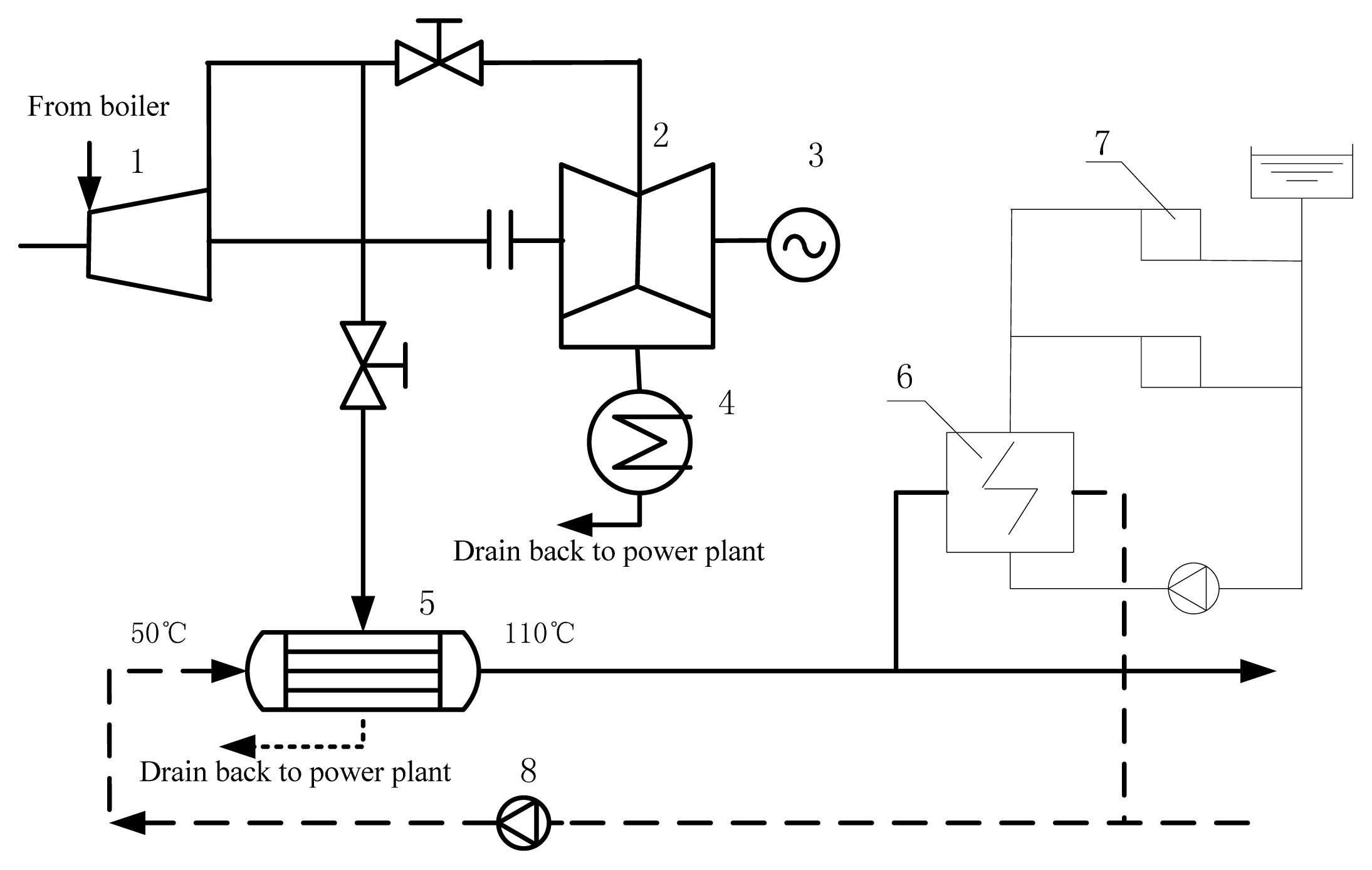
The ECM is widely applied in China with different CHP units, including those with the capacity of 300 MW or more, as shown in Figure 1. In the conventional ECM system, the heating steam is extracted at the outlet point of the IPC, which can be adjusted by throttles and then condensed in the heater for the heat grid (HHG). This process transfers heat to the water in the indirect heat grid, and the drain water returns to the de-aerator in the power plant.
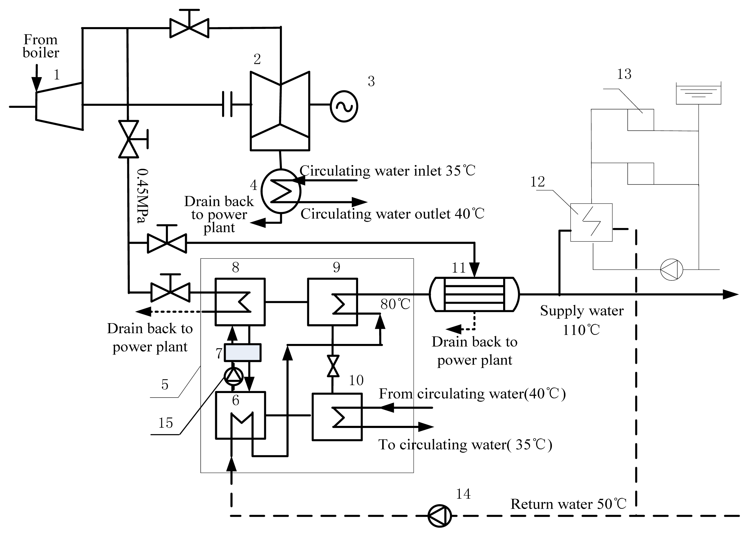
Large-scale AHPM (with its turbine power capacity of 200 MW or more) has recently been applied in China, with a representative project designed by Tsinghua University [11,12]. In AHPM, the heat pump is driven by the extracted steam, which is then used to obtain heat from the circulating water to heat the water from the heat grid. The heat grid can theoretically reuse all the energy at the cold end, making it an effective type of technology for waste heat utilisation (Figure 2).
In the AHPM, the water returning from the heat grid is heated by the heat pump to a temperature of 80 °C to 90 °C using the extracted steam as its driving heat source; another heat exchanger is used to further heat the water to the supply temperature of the heat grid, e.g., 110 °C.
The application of the LVM has a long history; its basic principle of increasing the turbine exit temperature by increasing the back pressure, which results in circulating water with a sufficiently high temperature, has met users’ needs satisfactorily, as shown in Figure 3. The circulating water is delivered directly to users for space heating. This mode loses some turbine power because of the increase in the back pressure. However, compared with the ECM, this loss is less; hence, the LVM is an efficient energy-saving mode of CHP [13]. However, its large-scale application is restricted by many elements, and the largest applied unit of the LVM in China is just 100 MW.
District heating (DH) with CHP technology is an integrated system that includes the power plant, the heat grid, and the users. One of its disadvantages, however, is that it cannot sufficiently reflect the real energy consumption level of the entire process when evaluating just one or two parts of the system, which is always the case when evaluating actual issues. Therefore, this paper examines the entire system of space heating with the three aforementioned modes according to the actual heating load of a county in Xi’an. To avoid the problem of energy consumption allocation, the net power output of the whole heating system (Pn) is identified as the most direct evaluation indicator in assessing the entire system on the premise of the same fuel input. In other words, the net electrical power of whole systems with different modes is compared when the main steam flow of the entire power unit is the same and constant. Pn is calculated as follows:
where Ps is the net output of the power plant, which is the difference between the generated power and the auxiliary power in the power plant, and Pw is the power consumed by the pump in the heat grid.
The case study is located in the Xi’an District, which has a heating area of 4.5 million m2. In this area, the designed outdoor temperature ( ) is −5 °C [14], the designed indoor temperature (ti) is 18 °C, and the designed heat load is 45 W/m2. The existing unit in the power plant is a 200 MW air-cooled unit, and heating steam can be extracted from the connecting pipe between the IPC and LPC of the steam turbine [15]. The basic parameters of the unit are shown in Table 1.
3. Analysis of the Heating Modes
3.1. Calculation of the Heat Grid
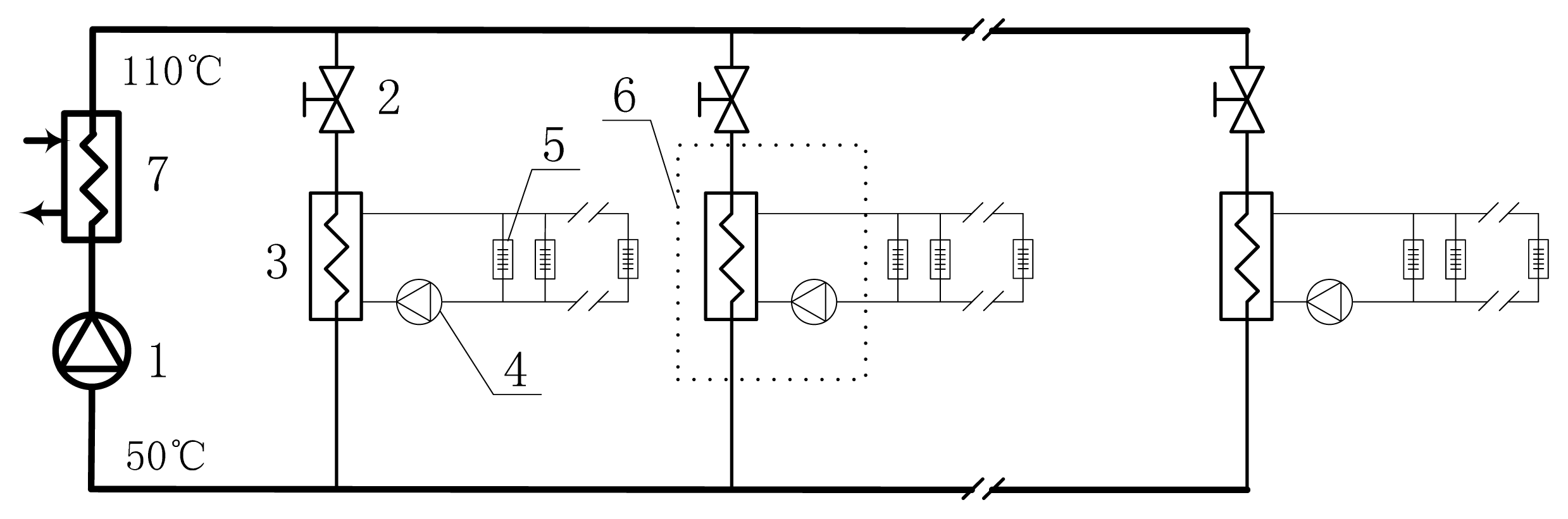
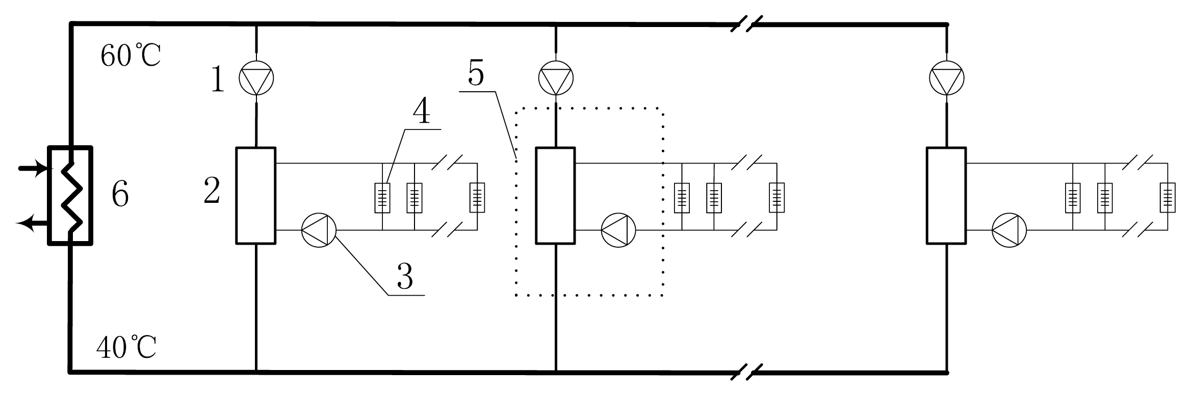
There are two main types of heat grids: direct and indirect [13]. With the branched two-pipe system in the current study, the direct heat grid is applied in the LVM, and the indirect heat grid is employed in both the ECM and the AHPM. The structures of the two grids are different and can be found in Figure 4 and Figure 5. As the conventional type of grid, the indirect one is extensively used in large-scale heating networks, while the direct grid is more common in small-scale heating networks with LVM. A large-scale direct grid should use distributed variable frequency pumps to overcome the unavoidable hydraulic disorder problem in a conventional heating grid.
3.1.1. Indirect Heat Grid
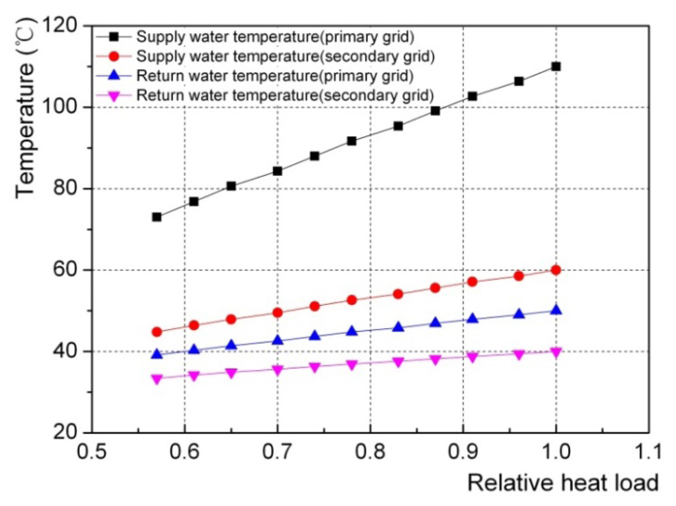
As shown in Figure 4, the indirect heat grid consists of both the primary and secondary grids. Here, heat is transferred from the primary to the secondary grid through a heat exchanger at the thermal station. The designed primary grid temperatures of the supply and the return water are set at 110 °C and 50 °C, respectively, whilst those of the secondary grid are set at 60 °C and 40 °C, respectively, based on the design data from a heat grid design department (Figure A1). The thermal insulation of the pipe is assumed to be perfect, and thus, the heat loss of the pipe net is disregarded. The hydraulic calculation for the studied primary grid is carried out by referring to relevant literature [16].
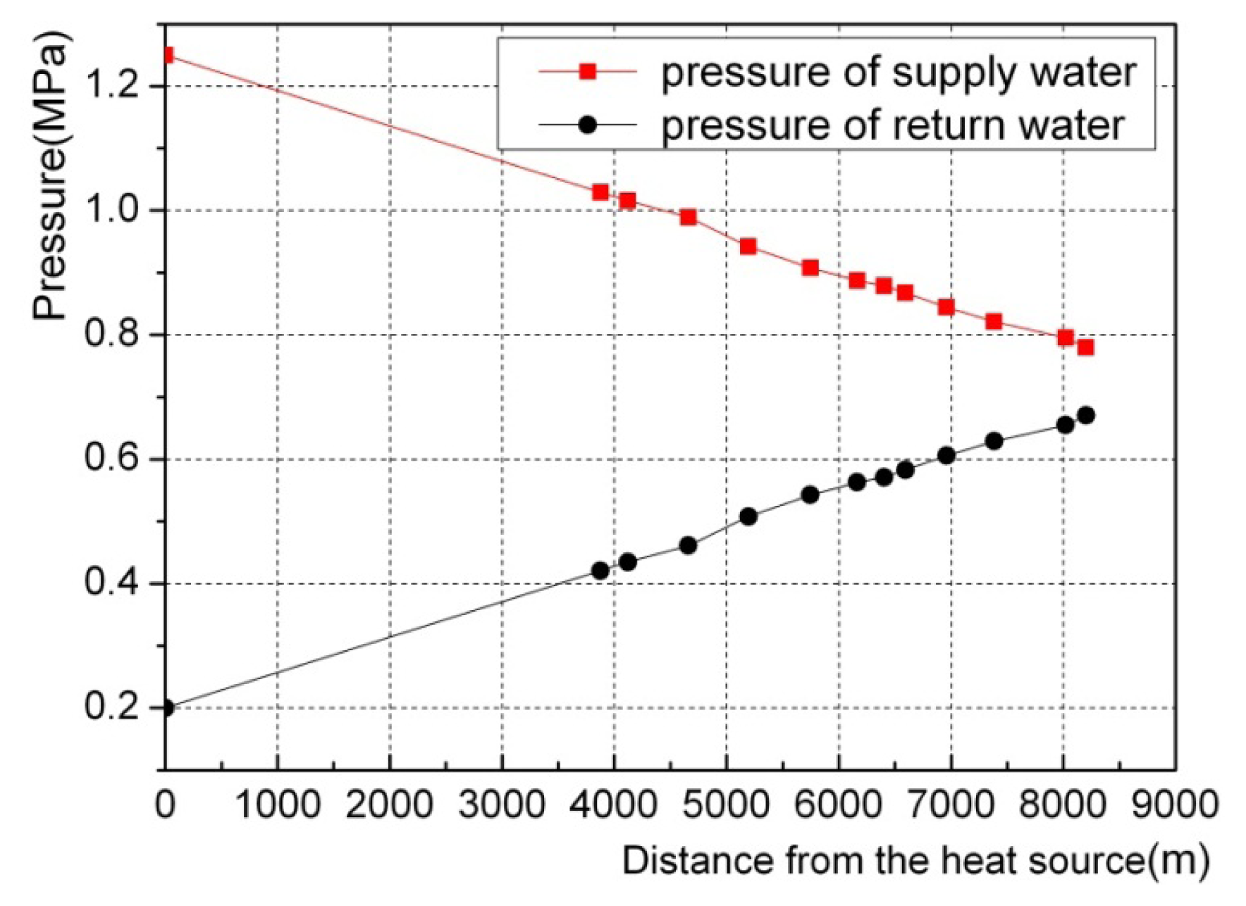
The pressures along the primary flow circuit of the farthest loop are shown in Figure 6. All the water in the primary grid is pressurised by the primary pump in the CHP plant and flows to the thermal stations. At the thermal stations, which are close to the CHP plant, part of the flow is throttled and delivered to the heat exchangers, where the heat is transferred to the secondary grids. In this type of grid, the hydraulic status is always unsteady when the grid is adjusted with the outdoor temperature, leading to hydraulic disorder in operating conditions, which is not suitable for LVM.
The secondary and primary grids have somewhat similar calculation principles; however, that of the secondary grid is more complicated because different buildings with different heights and distribution conditions have varied calculation results. In the case studied, the pressure drop of the secondary grid is uniformly assumed to be 0.2 MPa [17]. The primary circulating pump is placed at the power plant, and each thermal station has a secondary pump in the secondary grid, with all efficiency rates assumed to be 70% [18]. Using Equation (2), the power consumption (Pw) is calculated to be 1,903.2 kW for the entire heat grid, including the primary grid and the secondary one. The mass flow is constant when the heat load changes with the outdoor temperature, and thus, the heat grid power is also constant. This is expressed as:
where G is the mass flow of the water, ΔP is the pressure drop, ρ is the density of water, and η is the efficiency of the pump.
3.1.2. Direct Heat Grid
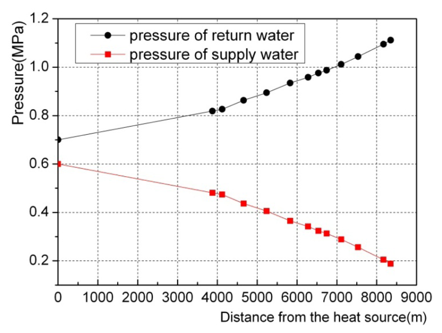
As shown in Figure 5, in the direct heat grid, the primary and the secondary grids are directly connected by a mixing tube with no heat exchangers. The designed primary grid temperatures of the supply and return water are 60 °C and 40 °C, respectively. Although the calculation principle of the direct heat grid is the same as that of the indirect heat grid, the distribution of the pumps for the direct heat grid is different from that of the indirect heat grid. The primary direct grid lacks a primary circulating pump, which is normally used to push water with a high pressure. As the variable frequency pumps are distributed at every thermal station to fetch water, the throttling phenomenon at the stations close to the power plant is avoided [19]. With the same assumptions as those for the indirect heat grid, the pressures along the primary flow circuit of the farthest loop are illustrated in Figure 7.
Compared with the indirect heat grid, the supply water line is easier to find under the return water line in the designed direct heat grid, which is shown in Figure 6. Here, water is fetched instead of pushed because of the distribution of the variable frequency pumps, and the mix tube has a decoupling function between the primary and secondary grid, which makes it possible to carry out a large-scale direct heat grid for the LVM through the design and under operating conditions. With the pump efficiency set at 70% and using the same assumptions as the indirect heat grid for the secondary grid, the Pw of the entire direct grid (including the primary one and the secondary one) is calculated as 6,004.1 kW. The flow rate is controlled when the heat load changes with the outdoor temperature; thus, the total power consumption of the direct heat grid is not constant.
3.2. ECM
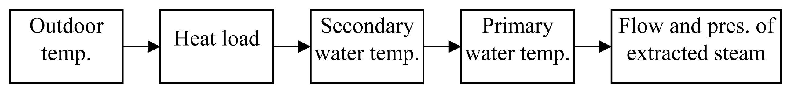
The ECM is an integrated system, which includes the heating units, the HHG, the heat grid, and the users (Figure 1). When the outdoor temperature changes, the heat loads (heat demand) of the heat users would change, accordingly. With the premise of a constant flow in the heat grid, the temperatures of the secondary and the primary heat grids should be changed, which is done by the adjustment of extracted steam flow the turbine using control valves. In another word, the flow rate of the extracted steam is adjusted by control valves according to the outdoor temperature; this is done to adapt to the changes of the heat load. The adjustment method is shown in Figure 8 (temp. means temperature, pres. means pressure) according to the relevant literature [20].
The outdoor temperature is obtained from the conventional designing data, and the relative heat load (Q̄) is obtained by Equation (3) [14]. For a different relative heat load, the water temperature of the secondary and primary grid can be obtained according to the relevant literature [21], as shown in Figure 9.
Furthermore, the flow and pressure of extracted steam can be obtained by a thermal balance calculation of the HHG [20]:
where Q is the heat load in the operating condition; Qd is the designed heat load; ti is the designed indoor temperature; is the outdoor temperature in the operating condition; and is the designed outdoor temperature.
To simplify the calculation, the terminal temperature difference of the HHG is set at 10 °C [22]. The pressure and flow rate of the extracted steam can be calculated using Equations (4) and (5), respectively, which are given by:
where tg is the supply water temperature of the heat grid, θ is the terminal temperature difference of HHG, Pc is the saturated pressure at the temperature of (tg + θ), hc is the enthalpy of the extracted steam, hc′ is the enthalpy of the saturated water, and Mc is the flow rate of the extracted steam.
Using the data obtained above, a process model is simulated using EBSILON PROFESSIONAL software to carry out the off-design calculation of the power generation unit (Figure 10) [23].
The basic principles for the heat exchanger components in EBSILON are basic thermodynamic equations and fluid mechanics equations. The Stodolar equation is used for the off-design calculation of the turbine. And the water steam property used is IF97 water steam database. The heat load changes with the outdoor temperature. And the flow of the extracted steam is regulated accordingly. The energy input of the whole system is kept constant, and the pressure and temperature levels of the live steam don’t change in the off-design simulation in this paper. The simulation results are listed in Table 2, which shows the relationship between the power generation and the relative heat load.
There are two main valves for the governing of the steam extraction. One is lain on the inlet pipe before Component 4 in Figure 10, and the other is lain on the pipe between IPC and LPC. With the operation of these two valves, the steam-extraction pressure decreases first and increases afterwards, as is shown in Table 2. When the outdoor temperature increases from −5 °C to 0 °C, the valve on the extracted steam pipe is fully open and the valve on the pipe between IPC and LPC is opened gradually to its largest opening position, at which condition the extraction pressure would decrease from 0.199 to 0.103 MPa. When the outdoor temperature increases from 0 °C to 5 °C, the valve on the extracted steam pipe would be closed gradually and the valve on the pipe between IPC and LPC stays at its largest opening position, at which condition the extraction pressure would increase from 0.103 to 0.140 MPa.
3.3. AHPM
For the AHPM in this paper, the absorption heat pump is used in the power plant, and the heat grid is the same as that in the ECM. The water returning from the heat grid has a temperature of 50 °C, and the supply temperature is 110 °C. The heat pump is an absorption heat pump, which is shown in Figure 2 and which is a device that transfers thermal energy from a low temperature source to a sink at a relatively higher temperature. The absorption heat pump consists of an evaporator, absorber, steam generator, and condenser (Figure 2). The absorption heat pump performs two main cycles, namely, the working medium cycle and the solution cycle. The working medium in the absorption heat pump is LiBr, and the LiBr-H2O solution is in the solution cycle. Low-pressure water vapour from the evaporator is absorbed by the solution in the absorber. The heat generated during the absorption process is used to heat the water in the primary heat grid. The solution pump circulates the diluted solution to the generator through the solution heat exchanger to turn it into an intermediate solution. The intermediate solution is boiled by the steam from the turbine to release water vapour, leaving behind a solution rich with LiBr, which is returned to the absorber to continue the solution cycle. In the condenser of the heat pump, the water vapour coming from the generator is condensed into liquid, which is passed via a throttling valve to the evaporator, where it changes to low pressure water vapour again to continue the working medium cycle [24]. For simplicity, some conditions are set below, using the literature [25] as a reference:
- (1)
The absorption heat pump is in a steady state.
- (2)
The export strong solution of the steam generator, the export diluted solution of the absorber, and the condenser and evaporator outlet refrigerant are all at their corresponding saturation pressures.
- (3)
The refrigerants, which are at the exit points of the steam generator, absorber, condenser and evaporator, have reached thermal equilibrium.
- (4)
The pressure and the heat loss are ignored.
- (5)
The power of the solution pump is excluded.
The driving heat source of the heat pump is the extracted steam with a pressure of 0.45 MPa. The inlet and outlet temperatures of the circulating water, which enters the evaporator as the cold source of the heat pump, are set to 40 °C and 35 °C, respectively. The outlet temperature of the heat grid water that exits the condenser of the heat pump is 80 °C. The system is designed based on the mass conservation equation and the energy conservation equation in every component. In addition, the coefficient of performance (COP) of the heat pump [26], which is the ratio of the heat absorbed by the heat grid water to the heat released by the extracted steam, is calculated to be 1.70 with the designed data according to literature [27]. The key figure of the designed heat pump is shown in Table 3.
During the entire heating period, the supply temperature of the primary grid changes with changes in the outdoor temperature, thus leading to the off-design operation of the heat pump. To simplify, the COP is assumed constant when the heat load changes. With the EBSILON PROFESSIONAL simulation mentioned in the previous section, the power generation of the unit is obtained, with the results enumerated in Table 4. When the outdoor temperature increases, the heat load is smaller, and the total flow of the extracted steam for district heating and for the HHG is also smaller (Figure 11). However, as shown in Table 4, the extracted steam flow of the heat pump increases because of the lower supply temperature when the relative heat load decreases (Figure 9), which means that the proportion of the heat supplied by the heat pump increases compared to that supplied by the HHG, and the latter value is finally reduced to 0.
3.4. LVM
In LVM, the back pressure of the turbine should be sufficiently high to satisfy the 60 °C/40 °C temperature requirement of the heat grid. The terminal temperature difference of the condenser is designed as 6 °C. Accordingly, the back pressure of the turbine in the designed condition is 26 kPa. The off-design calculation is essential when the back pressure changes and this can be obtained by an off-design simulation with the previously built EBSILON model. The result is shown in Figure 12.
A large-scale development of the LVM is limited by two main reasons. First, the steam flow requirement of the LPC is also large for a large-scale turbine. Given that the blades of the final stages are long, it is unsafe to operate the LVM at very low vacuum. Second, the adjustment of the heat grid is difficult given the large-scale direct grid mentioned above. Furthermore, the large flow of the grid water can also significantly increase the power consumption of the heat grid.
Two main measures have been employed for these problems. First, to conserve water, the air-cooled power unit has a well-developed design, in which the blades of the final stages are not very long. This feature makes it easy to operate the large-scale turbine at a relatively high back pressure. Second, as mentioned in Section 3.1, recently developed distributed variable frequency pumps can now reduce the power consumption of the heat grid [18]. This type of heat grid system is capable of solving operation problems and adjustment difficulties for the direct grid. Therefore, the main technical problems related to the development of the LVM with a large CHP unit and heat grid have been solved. The present study presents a typical design and analysis model of the large-scale LVM (Figure 3). Furthermore, the off-design calculation when the back pressure of the turbine increases is carried out by the system simulation with the same software as the ECM (Figure 12). There is no sliding pressure in the condenser following the change of heat load, and the flow of the primary grid is adjusted with the heat load. Therefore, the power generation of the CHP unit for this case with LVM is constant at 190,169.8 kW.
4. Comparison of Heating Modes
4.1 Comparison in Terms of the Energy Consumption
At the power plant side, power generation decreases as the heat load increases; the power generation advantage of the LVM compared with the other two modes becomes larger (Figure 13). However, at a larger heat load, the pumping power of the heat grid for the LVM becomes higher (Figure 14). Hence, the modes must be compared using the indicator Pn, as defined above. To simplify the calculation, the power consumption rate of the entire power plant is set as 6% (Table 1).
Table 5 shows the power generation of three heating modes at the design condition. The off-design results are shown in Figure 15. Overall, the net power of the LVM is the highest, whereas that of the AHPM is the lowest for the 200 MW unit studied. In order to get a more general conclusion, a similar case with an air-cooled 300 MW unit is studied with its result, as is shown in Figure 16. For the 300 MW unit studied, the AHPM has a lower fuel consumption level than the ECM, but the LVM is still the preferred selection in application. Therefore, it’s safe to conclude that the large-scale LVM should have a priority in the development of 200 MW/300 MW based CHP in future. With respect to AHPM and ECM, the fuel consumption level depends.
4.2. Preference Recommendation on the CHP Modes
4.2.1. Preference on Energy Saving
With its energy saving and emission reduction, the LVM is the preferred selection in applications. While the ECM and AHPM are a trade-off and should be considered in practice. This paper only focuses on the cases studied. Hence, the results may differ for varied CHP units with different operational cases, which could be simulated and analysed using the method employed in the paper.
4.2.2. Heating Capacity of the Modes
For the 200 MW based CHP, when the heating area expands to 5.5 million m2 (247.5 MW), the net power generation decreases accordingly (Figure 17). However, for the ECM, the heat load is insufficient for the expanded heating area. This is because of the limitation on the minimum cooling flow of the LPC (145 t/h), which can only supply a maximum heat load of 221.9 MW. The minimum cooling flow of the LPC must be guaranteed. Otherwise, the final stage of the LPC would operate at the windage condition, which would endanger the unit. Therefore, the heating capacity of the ECM would be limited by the minimum cooling flow of the LPC, and the relevant exhaust heat would not be delivered to heat users. The other two modes can perform better at this point.
4.2.3. Investment Considerations
Different system layouts have different investment considerations. For the case studied in this paper, the main equipment investments, besides the cost of labour and the equipment maintenance and depreciation, are as follows:
- ①
Investment in the CHP plant [28]. For ECM, there will be 3~4 heaters for the heat grid and 4~5 primary circulating pumps in the plant. Moreover, a new extraction pipeline should be installed by drilling on the pipe between the IPC and the LPC. For AHPM, new absorption heat pumps should be installed together with their control systems. To recycle the heat of the discharged steam from the LPC as the cold source of the heat pumps, a new water-cooled end should be built, including a new condenser, a new water-cooling tower, 3~4 circulating pumps and pipes with valves. For LVM, a new condenser, a new water-cooling tower, 3~4 circulating pumps and pipes with valves should be installed.
- ②
Investment in the heat grid. For ECM and AHPM, there will be no investment in the heat grid because the heating area is an old one, and there is already a conventional indirect grid with heat exchangers in the thermal stations. For LVM, the pipes in the heat grid should be replaced by new ones with larger diameters (approximately 1.6 times larger [16]). The heat exchangers should be replaced by distributed variable frequency pumps together with their control systems.
Based on the analysis above, for the case studied, the ECM would be a better choice because the AHPM has a lower net power generation level and the LVM has a larger investment and reformation difficulties because of the complete change of the heat grid. However, for newly built heating areas without a heat grid, the energy-saving feature of the LVM would be of great advantage.
5. Conclusions
- (1)
In the 200 MW case study, the net power generation of the LVM is 172.2 MW, whereas those of the ECM and AHPM are 149.2 and 137.3 MW, respectively, under the condition of a rated heating load. In the 300 MW case, these three values are 258.1 MW, 197.7 MW and 213.1 MW, respectively. Different CHP modes have varied energy consumption levels. In general, the LVM is the most satisfactory choice for space heating, followed by the ECM and the AHPM.
- (2)
The LVM and AHPM have the ability to supply a larger heat load compared with the ECM, which is limited by the minimum cooling flow of the low pressure cylinder.
- (3)
The heating modes studied in this paper are applicable for different conditions. Air-cooled units with a newly built heating area (i.e., an area where it is easy to build a new heat grid with distributed variable frequency pumps) are suitable for the LVM as an effective energy-saving option. Meanwhile, the conventional ECM is recommended for water-cooled units or old heating areas with an indirect grid, where rebuilding an indirect grid is not possible. Finally, the AHPM should be applied as an optional supplement to the ECM when the heat area is expanded.
Acknowledgments
The financial support from The Joint Funds of the National Natural Science Foundation of China (U1261210) and the National Science Fund for Distinguished Young Scholars (51025624) are sincerely acknowledged.
Appendix

Conflicts of Interest
The authors declare no conflict of interest.
- Author ContributionsYongping Yang conceived the research subject of this paper. Pei Feng Li carried out the calculation of the ECM and LVM, drafted the paper and final approved the version to be published. Yuyong Chen carried out the calculation of AHPM and validated the results. Zhiping Yang contributed to the conception and critical suggestions of the paper. Zhihua Ge revised the paper and directed this study.
References
- BP Group, BP Statistical Review of World Energy June 2011; BP Press Centre: London, UK, 2011.
- Tsinghua Building Energy Research Center, China Building Energy Conservation Annual Report of the Development Research in 2011, 1st ed; China Architecture and building press: Beijing, China, 2011. (In Chinese)
- Wu, D.W.; Wang, R.Z. Combined cooling, heating and power: A review. Progr. Energ. Combust. Sci 2006, 32, 459–495. [Google Scholar]
- Perdikaris, N.; Panopoulos, K.D.; Hofmann, Ph.; Spyrakis, S.; Kakaras, E. Design and exergetic analysis of a novel carbon free trigeneration system for hydrogen, power and heat production from natural gas, based on combined solid oxide fuel and electrolyser cells. Int. J. Hydrogen. Energ 2010, 35, 2446–2456. [Google Scholar]
- Lund, H. Large-scale integration of wind power into different energy systems. Energy 2005, 30, 2402–2412. [Google Scholar]
- Yagoub, W.; Doherty, P.; Riffat, S.B. Solar energy-gas driven micro-CHP system for an office building. Appl. Therm. Eng 2006, 26, 1604–1610. [Google Scholar]
- Akkaya, A.V.; Sahin, B.; Erdem, H.H. An analysis of SOFC/GT CHP system based on exergetic performance criteria. Int. J. Hydrogen. Energ 2008, 33, 2566–2577. [Google Scholar]
- Qiu, G.Q.; Liu, H.; Riffat, S. Expanders for micro-CHP systems with organic Rankine cycle. Appl. Therm. Eng 2011, 31, 3301–3307. [Google Scholar]
- Yang, J.C. The Reforming Design and Operating Analysis of Provision-Heating in Low Vacuum of the Turbine. Master Thesis, Liaoning Technical University, Fuxin, China, 1 May 2006. (In Chinese). [Google Scholar]
- Zhou, S.X.; Song, Z.P. On evaluation reference of energy utilizations. J. Eng. Thermophys 2008, 29, 1267–1271. (In Chinese). [Google Scholar]
- Fu, L.; Li, Y. A district heating system based on absorption heat exchange with CHP systems. Front. Energ. Power Eng. China 2010, 4, 77–83. [Google Scholar]
- Li, Y.; Fu, L.; Zhang, S.G.; Luo, Y.; Hu, P. Significance of Ca-oh technique for building energy supply industry in Beijing. Heat. Vent. Air Condit 2011, 41, 91–95. (In Chinese). [Google Scholar]
- Song, Z.P. A theoretical study on decentralized space heating system. Energ. Resour. Tech 2008, 130, 1–8. [Google Scholar]
- Cai, Q.L.; Shou, X.F. Heating load curve and its application for space heating. Dist. Heat 1991, 2, 1–10. (In Chinese). [Google Scholar]
- Mei, Y.Z.; Zhang, Q.X.; Zhang, Y. Feasibility study on the congeneration retrofit of 200 MW steam turbine units to extract steam from inter-connecting pipe in Junliangcheng power plant. Electr. Equip 2008, 9, 75–77. (In Chinese). [Google Scholar]
- Shi, Z.Y. Heating System Operation Regulation and Control, 1st ed; Tsinghua University Press: Beijing, China, 1994; pp. 27–42. (In Chinese) [Google Scholar]
- Li, X.R. Discussion of the proper scale of civil heating power station. Beijing Energ. Conservat 2002, 1, 20–22. (In Chinese). [Google Scholar]
- Zhu, H.G.; Dai, L.Y.; Zhang, R.T.; Zhu, G.X.; Yao, L.B.; Luo, J.Q. Numerical Simulation of the Internal Flow of a New-Type Shaft Tubular Pumping System. Proceedings of ASME-JSME-KSME 2011 Joint Fluids Engineering Conference (AJK2011), Hamamatsu, Japan, 24–29 July 2011.
- Chen, M. Heat-supply system with distributed variable frequency pump. Gas Heat 2008, 28, A12–A14. (in Chinese). [Google Scholar]
- Lin, Z.X. Research on Energy Saving of Cooling Source Filed and Coupling Mechanism of Combined Heat and Power System. Ph.D. Thesis, North China Electric Power University, Beijing, China, 2011. (In Chinese). [Google Scholar]
- He, P.; Sun, G. Heating Engineering, 4th ed; China Architecture & Building Press: Beijing, China, 2009; pp. 277–292. (In Chinese) [Google Scholar]
- Yu, J.Z. Principle and Design of Heat Exchanger, 1st ed; Beihang University Press: Beijing, China, 2006; pp. 182–185. (In Chinese) [Google Scholar]
- Wang, L.G.; Yang, Y.P.; Morosuk, T.; Tsatsaronis, G. Advanced thermodynamic analysis and evaluation of a supercritical power plant. Energies 2012, 5, 1850–1863. [Google Scholar]
- Keil, C.; Plura, S.; Radspieler, M.; Schweigler, C. Application of customized absorption heat pumps for utilization of low-grade heat sources. Appl. Therm. Eng 2008, 28, 2070–2076. [Google Scholar]
- Bakhtiari, B.; Fradette, L.; Legros, R.; Paris, J. A model for analysis and design of H20-LiBr absorption heat pumps. Energ. Convers. Manag 2011, 52, 1439–1448. [Google Scholar]
- Chen, D.; Xie, J.H. Heat Pump Technology and Application, 1st ed; Chemical Industry Press: Beijing, China, 2006; pp. 206–216. (In Chinese) [Google Scholar]
- Chen, D.; Xie, J.H. Hot Water and Heat Pump Device, 1th ed; Chemical Industry Press: Beijing, China, 2009; pp. 178–191. (In Chinese) [Google Scholar]
- Electric Power Planning & Engineering Institute, Referenced Cost Index for the Design of Thermal Power Engineering 2010, 1st ed; China Electric Power Press: Beijing, China, 2011; pp. 1–52. (In Chinese)


| Parameter(unit) | Value | Parameter (unit) | Value |
|---|---|---|---|
| Unit type (−) | NZK200-13.2/535/535 | Reheated steam flow (kg/h) | 5.35 × 10⁵ |
| Rated capacity (kW) | 2.00 × 10⁵ | Reheated steam temp. (°C) | 535 |
| Main steam flow (kg/h) | 6.12 × 10⁵ | Reheated steam pres. (MPa) | 2.23 |
| Main steam temp. (°C) | 535 | Minimum cooling flow of LPC (t/h) | 145 |
| Main steam pres. (MPa) | 13.24 | Designed auxiliary power ratio (−) | 0.06 |
| Back pres. (MPa) | 0.014 | Stages of regenerative system (−) | 7 |
| Outdoor temp.°C | −5 | −4 | −3 | −2 | −1 | 0 | 1 | 2 | 3 | 4 | 5 |
|---|---|---|---|---|---|---|---|---|---|---|---|
| Relative heat load | 1 | 0.96 | 0.91 | 0.87 | 0.83 | 0.78 | 0.74 | 0.70 | 0.65 | 0.61 | 0.57 |
| Heat load (MW) | 202.5 | 193.7 | 184.9 | 176.1 | 167.3 | 158.5 | 149.7 | 140.9 | 132.1 | 123.3 | 114.5 |
| Extraction pressure (MPa) | 0.199 | 0.175 | 0.153 | 0.133 | 0.116 | 0.103 | 0.110 | 0.118 | 0.125 | 0.133 | 0.140 |
| Extraction flow (t/h) | 302.9 | 290.8 | 278.5 | 266.2 | 253.8 | 240.9 | 224.6 | 208.9 | 193.5 | 178.6 | 164.0 |
| Power generation (MW) | 163.1 | 167.0 | 171.0 | 174.9 | 178.8 | 182.2 | 182.3 | 182.6 | 183.0 | 183.5 | 184.2 |
| Parameter | Unit | Result | Parameter | Unit | Result |
|---|---|---|---|---|---|
| Extracted steam Flow of heat pump | t/h | 105.9 | Heat flow of solution heat exchanger | MW | 20.93 |
| Extracted steam Flow of heater for heat grid | t/h | 142.6 | Heat flow of absorber | MW | 56.38 |
| COP of heat pump | - | 1.70 | Heat flow of condenser | MW | 45.19 |
| Power generation | MW | 151.2 | Heat flow of generator | MW | 59.73 |
| Heat flow of heat pump | MW | 101.6 | Heat flow of evaporater | MW | 41.83 |
| Outdoor temp.(°C) | −5 | −4 | −3 | −2 | −1 | 0 | 1 | 2 | 3 | 4 | 5 |
|---|---|---|---|---|---|---|---|---|---|---|---|
| Relative heat load | 1 | 0.96 | 0.91 | 0.87 | 0.83 | 0.78 | 0.74 | 0.70 | 0.65 | 0.61 | 0.57 |
| Heat load (MW) | 202.5 | 193.7 | 184.9 | 176.1 | 167.3 | 158.5 | 149.7 | 140.9 | 132.1 | 123.3 | 114.5 |
| Extracted steam for heat pump (t/h) | 105.9 | 109.3 | 113.0 | 116.6 | 120.3 | 124.1 | 127.9 | 131.7 | 135.7 | 127.5 | 117.6 |
| Extracted steam for HHG (t/h) | 142.6 | 125.3 | 108.0 | 90.60 | 73.20 | 55.70 | 38.10 | 18.50 | 0 | 0 | 0 |
| Power generation (MW) | 151.2 | 153.0 | 154.9 | 156.7 | 158.6 | 160.5 | 162.4 | 164.6 | 166.7 | 167.8 | 169.3 |
| LVM | ECM | AHPM | |
|---|---|---|---|
| Power generation of the CHP unit (MW) | 190.2 | 163.1 | 151.2 |
| Power consumption of the power plant (MW) | 12.00 | 12.00 | 12.00 |
| Power consumption of the heat grid (MW) | 6.004 | 1.903 | 1.903 |
| Net power generation Pnet (MW) | 172.2 | 149.2 | 137.3 |
© 2014 by the authors; licensee MDPI, Basel, Switzerland This article is an open access article distributed under the terms and conditions of the Creative Commons Attribution license (http://creativecommons.org/licenses/by/3.0/).
Share and Cite
Li, P.F.; Ge, Z.; Yang, Z.; Chen, Y.; Yang, Y. District Heating Mode Analysis Based on an Air-cooled Combined Heat and Power Station. Entropy 2014, 16, 1883-1901. https://doi.org/10.3390/e16041883
Li PF, Ge Z, Yang Z, Chen Y, Yang Y. District Heating Mode Analysis Based on an Air-cooled Combined Heat and Power Station. Entropy. 2014; 16(4):1883-1901. https://doi.org/10.3390/e16041883
Chicago/Turabian StyleLi, Pei Feng, Zhihua Ge, Zhiping Yang, Yuyong Chen, and Yongping Yang. 2014. "District Heating Mode Analysis Based on an Air-cooled Combined Heat and Power Station" Entropy 16, no. 4: 1883-1901. https://doi.org/10.3390/e16041883