Article

Numerical Investigation on the Temperature Characteristics of the Voice Coil for a Woofer Using Thermal Equivalent Heat Conduction Models

1
Department of Mechanical Engineering, Dong-A University, Hadan 840, Saha-gu, Busan 604-714, Korea
2
Graduate School of Mechanical Engineering, Dong-A University, Hadan 840, Saha-gu, Busan 604-714, Korea
*
Author to whom correspondence should be addressed.
Entropy 2014, 16(7), 4121-4131; https://doi.org/10.3390/e16074121
Submission received: 21 May 2014 / Revised: 3 July 2014 / Accepted: 7 July 2014 / Published: 21 July 2014

Abstract

:
The objective of this study is to numerically investigate the temperature and heat transfer characteristics of the voice coil for a woofer with and without bobbins using the thermal equivalent heat conduction models. The temperature and heat transfer characteristics of the main components of the woofer were analyzed with input powers ranging from 5 W to 60 W. The numerical results of the voice coil showed good agreement within ±1% of the data by Odenbach (2003). The temperatures of the voice coil and its units for the woofer without the bobbin were 6.1% and 5.0% on average, respectively; lower than those of the woofer with the bobbin. However, at an input power of 30 W for the voice coil, the temperatures of the main components of the woofer without the bobbin were 40.0% higher on average than those of the woofer obtained by Lee et al. (2013).

1. Introduction

Speakers are designed to reproduce the audio signals that they receive, project them at a higher level and provide a greater spread of sound above the normal acoustic level of the input powers [1]. Speakers are normally used with amplifiers to amplify the higher acoustic levels for providing a pleasing sound with greater spread. The speakers and equipment for applications, such as portable devices, vehicles and indoor and outdoor theaters, are mainly decided by the usage purposes and the available space, capacity and performance. The speakers are divided with regard to the types and structures of the units into tweeters, midrange and woofers [2]. Generally, the units of these speakers consist of a damper, bobbin, voice coil, top plate, yoke, magnet and bottom plate, as shown in Figure 1. These parts have important roles in deciding the performance of the speakers [3]. Figure 1 shows a cross-sectional view of the tested woofer. The voice coil is a key unit of the speakers that performs energy conversion across the electrical, mechanical and acoustic components [4]. The energy conversion efficiency of the voice coils is under 10%, due to thermal and mechanical losses of over 90%, as the input power supplied to the voice coil is transformed into audio sound signals [5]. When operating the speakers for a very long time with excessive input power, the voice coils could experience lower sound quality and harmonic distortion, due to a high temperature. In addition, in rare, but severe, cases, this could cause a fire [6]. Therefore, to improve the sound quality and the performance stability of the speakers, studies on the heat transfer characteristics of the voice coil and its units are necessary. Recently, Chang et al. (2013) experimentally and numerically investigated the total harmonic distortion (THD) in a moving-coil loudspeaker. They suggested a novel approach to reduce the THD of a moving-coil loudspeaker with non-linear parameters and supplied a 10% reduction of THD by displacing the initial position of the voice coil [7]. Hong et al. (2004) studied the performance improvement of a diaphragm for a micro-speaker using the Taguchi method in discrete design space. They reported that the second natural frequency of the diaphragm for the micro-speaker decreased by 37%, while maintaining a twisted mode shape [8]. Lee et al. (2013) analyzed the temperature characteristics of the voice coil for a woofer using a ferrofluid with the input acoustic signals. As a result, the temperature of the voice coil for the woofer with the ferrofluid was 51.0% lower than that without ferrofluid at an input power of 40 W [9].
However, precise and concise studies on the temperature of heat transfer characteristics and on improvements for the performance of the woofer have been limited. Therefore, the objective of this study is to numerically investigate the characteristics and enhancement of the heat transfer of the voice coil for a woofer with and without bobbins using the thermal equivalent heat conduction models. In addition, due to the critical limitation of the maximum power of the woofers with the ohmic heat generated by the voice coils, the temperature characteristics of the voice coil for the tested woofer with and without a bobbin were observed while varying the input power.

2. Numerical Analysis

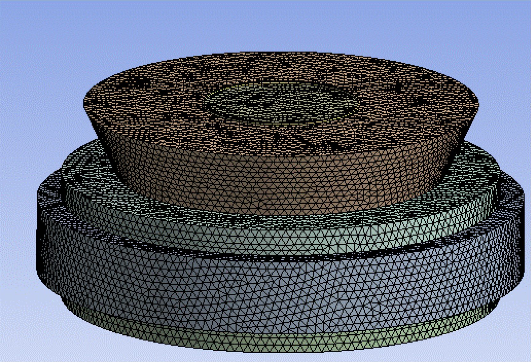
2.1. Numerical Method

A 200-W woofer with an 8-inch diaphragm consisting of a damper, bobbin, voice coil, top plate, yoke, magnet and bottom plate was investigated, as shown in Figure 1 [10]. The damper located over the voice coil could support the vertical motion of the voice coil and diaphragm. The bobbin was made of polyimide, which has heat-resistant properties. Like the human voice, the goal of the voice coil is to generate sound when input power is supplied to form a magnetic field. The voice coil was made of copper wound around the bobbin. Both the top and bottom plates were made of pure iron and were used for the magnetic field flow control and the magnetic field strength enhancement generated by the permanent magnet. The permanent magnets used in woofers are generally divided into ferrite, alnico and rare earth elements. The permanent magnet used in this study was of the ferrite type. The magnet generates a magnetic field to interact with the magnetic field generated by the voice coil.
A yoke consisting of pure iron was located at the center of the woofer for both the magnetic field flow control and the magnetic field strength enhancement generated by the voice coil [11]. Table 1 shows the specifications of the main components for the woofer. The notations used in Table 1 were D (Outer Diameter), d (Inner Diameter) and H (Height). 3D modeling of the woofer was done using SolidWorks.
Figure 2 shows the configurations of the 3D modeling for the woofers with and without the bobbin. In order to analyze the effect of the bobbin, woofers with and without a bobbin were considered, as shown in Figure 2a,b respectively [12]. The heat transfer analysis was numerically performed using commercial numerical analysis software (ANSYS CFX, FLUID FLOW Tool) [13]. The mesh map of the tested physical model was made using tetrahedron elements with a maximum size of 2.0 mm and minimum size of 0.01 mm, comprising 406,210 elements and 74,372 nodes. Figure 3 shows the mesh map of the physical model. The heat transfer of the woofer was analyzed using the k-ε model [14]. Table 2 shows the numerical conditions used in the simulation. The temperature and pressure of the air inside the woofer system were set to 25 °C and 101.3 kPa. The gravitational force was 9.8 m/s2. Additionally, the nominal impedance of the woofer was 8.0 Ω. In order to calculate the voice coil temperature, the input power supplied to the voice coil of the woofer was varied from 5 W, 15 W, 30 W, 45 W to 60 W. The working fluid was air. Table 3 shows the thermodynamic properties of the main components for the woofer. The thermal conductivities of the pure iron, copper, permanent magnet and air were 60.5, 401, 50 and 2.61 × 10⁻² Wm−1 K−1, respectively. The specific heat capacities of the pure iron, copper, permanent magnet and air were 4.34 × 10², 3.85 × 10², 4.0 × 10² and 1.0044 × 10³ J kg−1 K−1, respectively.

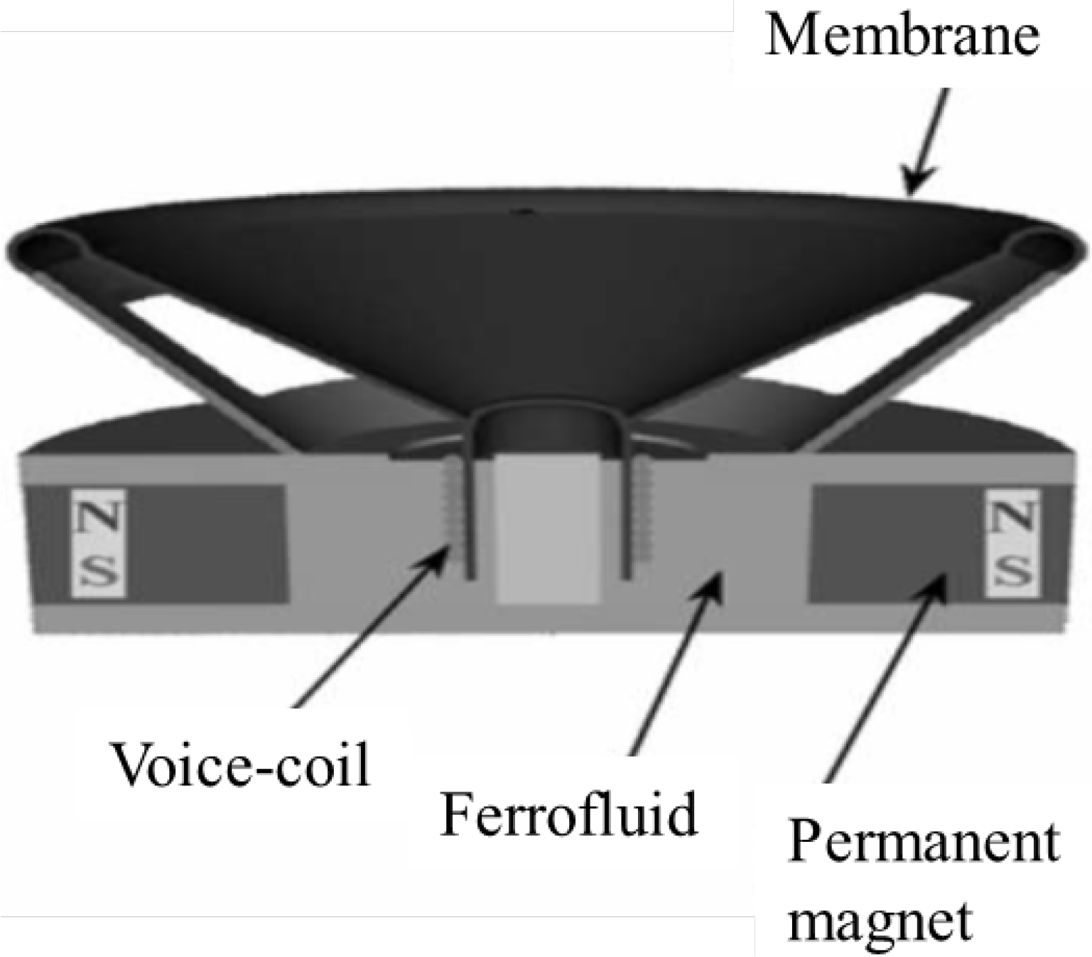
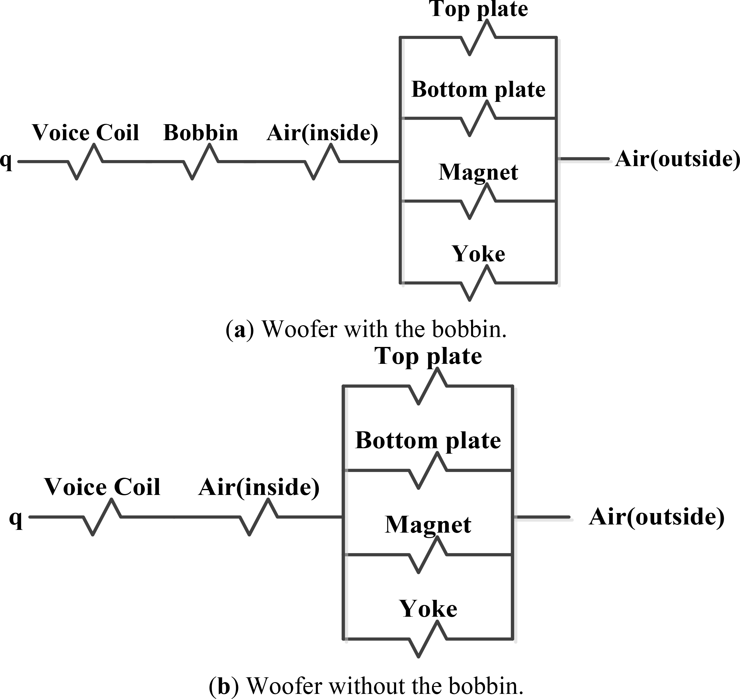
2.2. Heat Transfer Models

Figure 4 shows the convergence criterion of the numerical analysis for the woofer with the bobbin at an input power of 15 W and an ambient temperature of 298 K. The temperature of the tested voice coil was increased with time. After 130 s, the temperature increased steadily and converged at 439 K. Then, the deviations of the voice coil temperature were within 10−3. Figure 5 shows the heat transfer models using the equivalent thermal circuit methods. The equivalent thermal circuit models with a combination of the serial and parallel configurations were developed for the prediction of the voice coil temperature of the tested woofers with and without the bobbins [15,16]. The temperatures of the tested woofers were predicted using the developed thermal models.

3. Results and Discussion
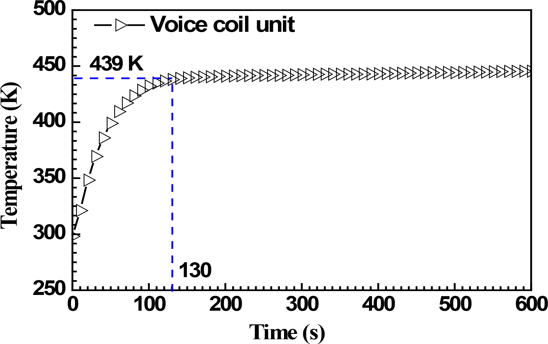
3.1. Validation

Figure 6 shows the voice coil temperature of the tested woofer with the bobbin in comparison with the results by Odenbach (2003) [17]. Both results were compared with input powers ranging from 5 W to 60 W. The numerical results show good agreement within ±1% of the data by Odenbach (2003) [17]. In addition, the voice coil temperature of the woofer increased linearly with the input powers. The voice coil temperature could be theoretically calculated using Equation (1). The temperature increase of the voice coil could be calculated by the resistance increase with the rising of the input power, as mentioned in Ciprian (2005) [18].
R th = T coil / P e
where Pe is the applied electric power.

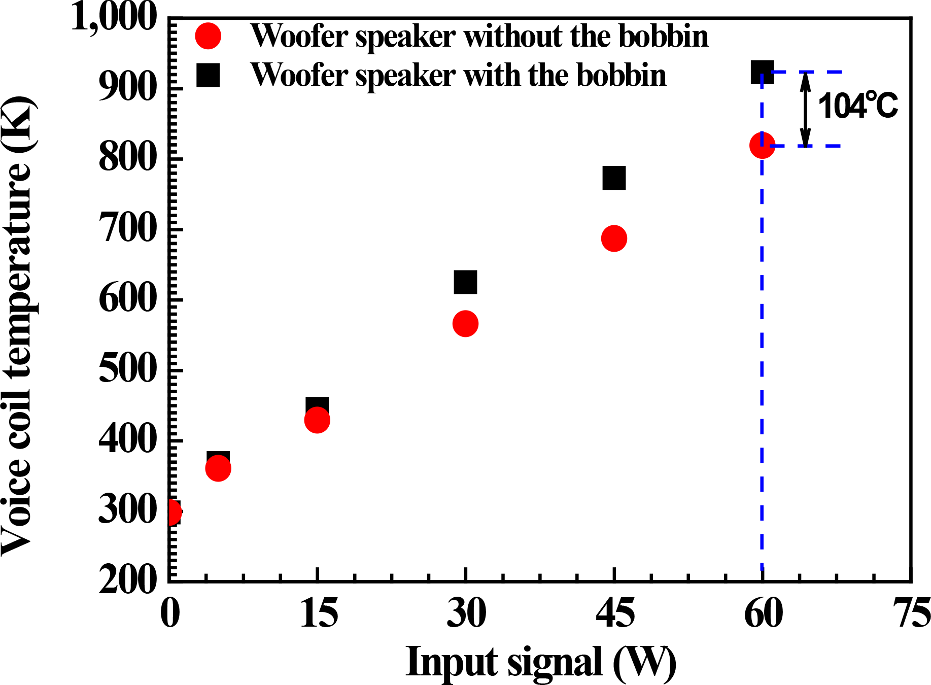
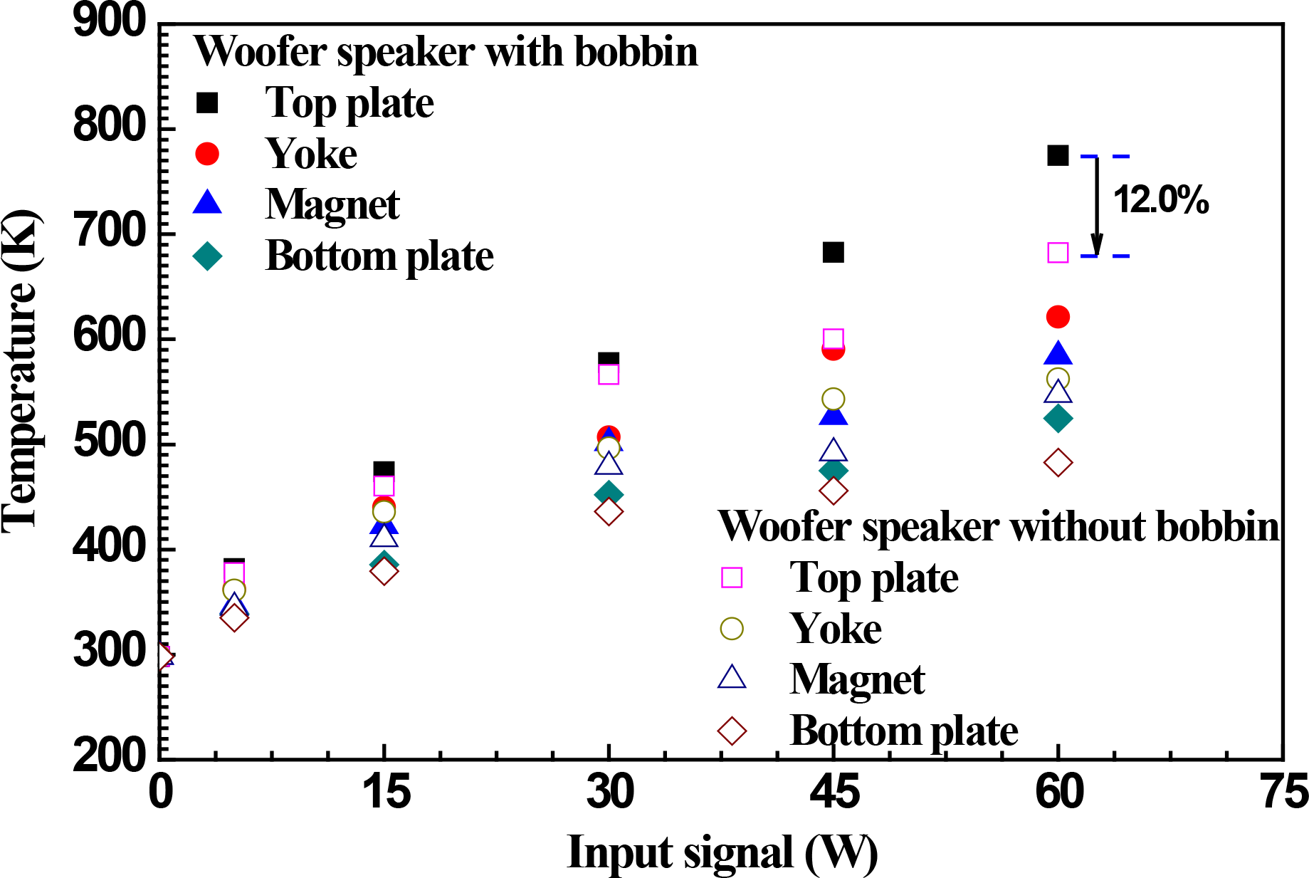
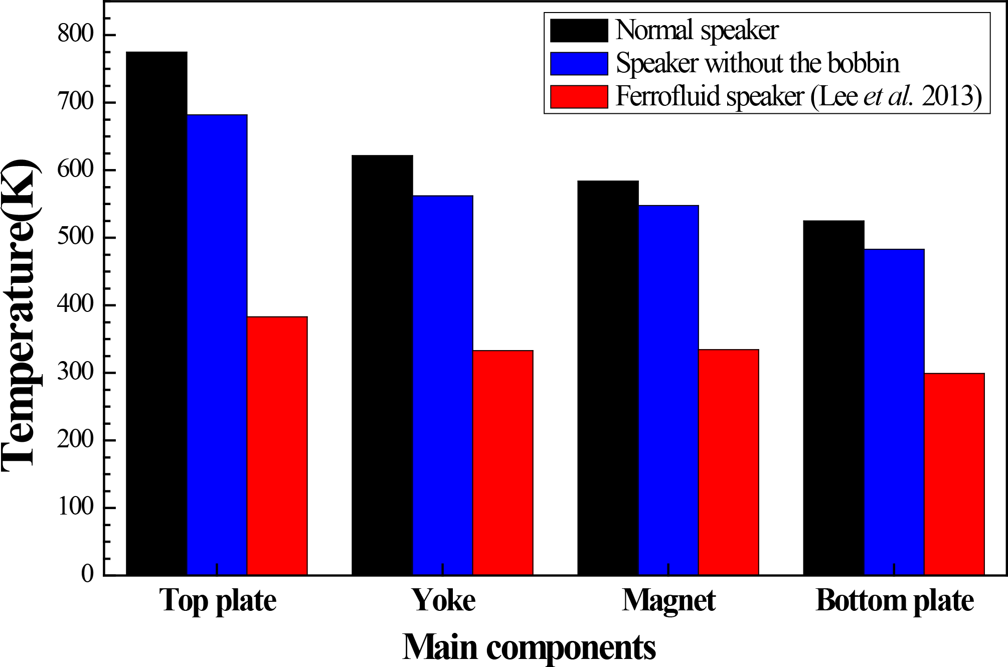
3.2. Heat Transfer Characteristics

Table 4 shows the heat transfer characteristics of the woofers with and without the bobbins and input powers ranging from 5 W to 60 W. Because the heat of the voice coils is generated proportionally to the increase of the input powers, the heat generated at the voice coils by the input powers was transferred toward the center direction of the other components, as shown in Table 4. The heat of the voice coil was transferred to the top plate and then to the permanent magnet. In addition, the heat transfer from the voice coil to other components of the woofer without the bobbin was superior to that with the bobbin. This is because the heat transfer area of the voice coil of the woofer without the bobbin was increased with the decrease of the thermal resistance.
Figure 7 shows the effects of the bobbin on the voice coil temperature for the woofers with the input powers. The voice coil temperature of the woofer without the bobbin was 6.1% lower on average than that with the bobbin within the tested input power ranges, because the heat generated at the woofer without the bobbin with the input powers was dissipated effectively with less thermal resistance [19]. Furthermore, the effects of the bobbin were increased with the input powers. The voice coil temperature of the woofer without the bobbin at the input power of 60 W was decreased by 104 °C compared with the woofer with the bobbin. This is because the heat transfer rate of the voice coil of the woofer without the bobbin was faster than that of the woofer with the bobbin, as shown in Table 4.
Figure 8 shows the temperature and heat transfer characteristics of the main components, except for the voice coil, for the woofers with and without the bobbin. The temperatures of the main components of the woofer without the bobbin were 5.0% lower on average than those of the woofer with the bobbin. The temperatures of the top plate for woofers with and without the bobbins increased by 160.0% and 128.9%, respectively, with the increase of the input powers from 5 W to 60 W. However, the increasing rate of the temperature of the main components for the woofer without the bobbin was lower than that of the woofer with the bobbin. In addition, the temperature of the top plate for the woofer without the bobbin was 12.0% lower than that for the woofer speaker with the bobbin at an input power of 60 W. Based on the results of Figures 7 and 8, the bobbin was a key parameter related to the heat transfer of the main components for the woofers. Its effect was greater with the input power increasing.
Figure 9 shows the temperature characteristics of the components of the ferrofluid and normal woofers obtained from Lee et al. (2013) [9]. At the input powers of 10 W and 50 W of the voice coil, the main components of the woofer without the bobbin tested in this study showed lower temperatures than those of the woofer with the bobbin obtained from Lee et al. (2013) [9], although they showed higher temperatures than the ferrofluid woofer. Generally, the ferrofluid woofer shows more effective heat transfer characteristics than the normal woofers [20]. At the input power of 30 W of the voice coil, the temperatures of the main components of the woofer without the bobbin were 9.8% lower on average than those of the ferrofluid woofer obtained from Lee et al. (2013) [9]. However, they were 40.0% higher on average than those of the main components of the ferrofluid woofer obtained from Lee et al. (2013) [9].
Temperatures computed in this study are theoretically obtained by the numerical model applying the simple thermal equivalent heat conduction methods, but practical values would limit the temperatures to lower values. In addition, for improving the reality of the simulation model, we will consider and develop the thermal modeling of the woofer considering the transient phenomena reflecting the frequency and input power effects in the next article.

4. Conclusions

The temperature and heat transfer characteristics of the voice coil and its components for the woofers with and without bobbins using the thermal equivalent heat conduction models were numerically investigated with the input powers. The effects of the bobbin on the temperature and heat transfer of the voice coil and the main components for the woofers were also considered. The numerical results of the voice coil with the input currents showed good agreement within ±1% of the data by Odenbach (2003) [17], and the voice coil temperature of the woofer increased linearly with the input powers. The presence of the bobbin was a very important parameter related to the temperature and heat transfer characteristics of the main components of the woofers. The heat transfer from the voice coil to other components of the woofer without the bobbin was superior to that with the bobbin, due to the enhanced heat transfer rate and reduced thermal resistance at the voice coil of the woofer without the bobbin. The voice coil temperature of the woofer without the bobbin was 6.1% lower on average than that with the bobbin with all input powers. The temperatures of the main components of the woofer without the bobbin were 5.0% lower on average than those of the woofer with the bobbin. The temperatures of the top plate for the woofers with and without the bobbins increased by 160.0% and 128.9%, respectively, with the increase of the input powers from 5 W to 60 W. At the input power of 30 W of the voice coil, the temperatures of the main components of the woofer without the bobbin were 9.8% lower on average than those of the woofer obtained from Lee et al. (2013) [9]. However, they were 40.0% higher on average than those of the main components for the ferrofluid woofer obtained from Lee et al. (2013) [9].

Acknowledgments

This work was supported by the Dong-A University research fund.

Author Contributions

Moo-Yeon Lee is the first and the corresponding author. He designed the research and wrote the paper. All results and discussions are performed by Moo-Yeon Lee. Hyung-Jin Kim is a co-author. He performed the CFD analysis and drew figures in the paper. Both authors have read and approved the final manuscript.

Conflicts of Interest

The authors declare no conflict of interest.

References

  1. Lemarquand, G.; Ravaud, R.; Lemarquand, V.; Depollier, C. Mechanical properties of ferrofluids in loudspeakers. Audio Eng. Soc. Conv 2008, 125, 1–5. [Google Scholar]
  2. Lee, T.K.; Kim, B.S. The analysis of the non-linear parameter for the structure of an automotive woofer speaker. J. Korean Soc. Mech. Tech 2012, 14, 19–24. (In Korean) [Google Scholar]
  3. Kim, S.K. Recent technology trends in home speaker. J. Korean Inst. Electr. Electron. Mater. Eng. (KIEEME) 2006, 19, 33–43. (In Korean) [Google Scholar]
  4. Choe, C.S. The cause of the fire investigation practices—Karaoke speaker for the cause of the fire analysis (II). Korea Fire Prot. Assoc 2006, 116, 40–43. (In Korean) [Google Scholar]
  5. Awrejcewics, J.; Koruba, Z. Classical Mechanics: Applied Mechanics and Mechatronics; Springer: New York, NY, USA, 2012. [Google Scholar]
  6. Kim, S.J. Overview of speaker industry trends and film speaker technology. J. Korean Inst. Electr. Electron. Mater. Eng. (KIEEME) 2006, 19, 13–23. (In Korean) [Google Scholar]
  7. Chang, C.; Wang, C.C.; Shiah, Y.C.; Huang, J.H. Numerical and experimental analysis of harmonic distortion in a moving-coil loudspeaker. Commun. Nonlinear Sci. Numer. Simul 2013, 18, 1902–1915. [Google Scholar]
  8. Hong, D.K.; Woo, B.C.; Ahn, C.W. A study on performance improvement of daiphgram for micro speaker using table of orthogonal array. Proceedings of the KSPE Autumn Conference, Busan, South Korea, 21–22 October 2004; pp. 298–301.
  9. Lee, M.Y.; Kim, H.J.; Lee, W.Y. Numerical analysis on temperature characteristics of the voice coil for woofer speaker using ferrofluid. J. Korean Magn. Soc 2013, 23, 166–172. (In Korean) [Google Scholar]
  10. Kim, H.J.; Kim, D.W.; Lee, M.Y. Experimental study on the heat transfer characteristics of woofer speaker unit. J. Korea Acad. Ind. Coop. Soc 2014, 15, 2623–2627. (In Korean) [Google Scholar]
  11. Lee, M.Y.; Kim, H.J. Heat transfer characteristics of the speaker using nano-sized ferrofluid. Entropy 2014. submitted for publication. [Google Scholar]
  12. Oh, S.J. Fundamentals of Loudspeaker Engineering; SeokHakDang: Seoul, South Korea, 2006; pp. 108–113. [Google Scholar]
  13. Menter, F.; Ferreira, J.C.; Esch, T.; Konno, B.; Germany, A.C. The SST turbulence model with improved wall treatment for heat transfer predictions in gas turbines. Proceedings of the International Gas Turbine Congress, Tokyo, Japan, 2–7 November, 2003. IGTC2003-TS-059.
  14. Speziale, C.G.; Thangam, S. Analysis of an RNG based turbulence model for separated flows. Int. J. Eng. Sci 1992, 30, 1379–1388. [Google Scholar]
  15. Koh, S.G.; Lee, K.J.; Kang, J.H.; Sung, K.H.; Kim, C.J. Development of a temperature prediction tool for voice coils in loudspeakers using CFD. In Proceedings of the KSME Spring Conference, Gangwon-do, South Korea, 23–25 April 2008; pp. 41–44.
  16. Incropera, F.P.; Lavine, A.S.; Bergman, T.L.; DeWitt, D.P. Principles of Heat and Mass Transfer; Wiley: NewYork, NY, USA, 2013; pp. 112–117. [Google Scholar]
  17. Odenbach, S. Ferrofluids magnetically controlled suspensions. Colloids Surf. A Physicochem. Eng. Asp 2003, 217, 171–178. [Google Scholar]
  18. Ionescu, C.; Codreanu, N.D.; Golumbeanu, V.; Svasta, P. Thermal simulation of a high power loudspeaker. Proceedings of the IEEE Spring Seminar on Electronics Technology, Wiener Neustadt, Austria, 19–22, May, 2005; pp. 134–139.
  19. Borwick, J. Loudspeaker and Headphone Handbook, 3rd ed; FocalPress: Waltham, MA, USA, 2001; pp. 76–81. [Google Scholar]
  20. Mayer, D. Future of electrotechnics: Ferrofluids. Adv. Electr. Electron. Eng 2011, 7, 9–14. [Google Scholar]
Figure 1. Schematic diagram of the tested woofer (cross-sectional view).
Entropy 16 04121f1
Figure 2. Configurations of the woofer with and without a bobbin.
Entropy 16 04121f2
Figure 3. Mesh map of the model.
Entropy 16 04121f3
Figure 4. Convergence criterion of the numerical analysis.
Entropy 16 04121f4
Figure 5. Heat transfer models using the thermal equivalent circuit technique for the tested woofers.
Entropy 16 04121f5
Figure 6. Voice coil temperature of the tested woofer with the bobbin in comparison with previous data.
Entropy 16 04121f6
Figure 7. The effects of the bobbin on the voice coil temperature for the woofers with the input powers.
Entropy 16 04121f7
Figure 8. Temperature and heat transfer characteristics of the main components for the woofers with and without the bobbins.
Entropy 16 04121f8
Figure 9. Temperature characteristics of the main components of the ferrofluid and normal woofers at an input power of 30 W.
Entropy 16 04121f9
Table 1. Specifications of the woofer.
ComponentsSize (D × d × H, mm)Specifications
Damper75 × 45 × 16Fiber paper
Bobbin36 × 35 × 35Polyimide
Voice coil(with bobbin)36.7 × 36.5 × 14Copper
Voice coil(without bobbin)36.7 × 35.2 × 27Copper
Top plate100 × 39 × 6Pure iron
Permanent magnet111 × 60 × 17Ferrite
Bottom plateD: 100, H: 6Pure iron
YokeD: 35, H: 23Pure iron
Table 2. Numerical conditions.
ComponentsSpecifications
Woofer (allowable max. power, W)200
Working fluidAir
Pressure (kPa)101.3
Input power (W)5, 15, 30, 45, 60
Temperature (K)298
Gravitational acceleration (m/s2)9.8
Nominal impedance (Ω)8.0
Table 3. Thermodynamic properties of the woofer.
ComponentsSpecifications
Pure ironDensity (kg m−3)7854
Specific heat capacity (J kg−1 K−1)4.34 × 10²
Thermal conductivity (Wm−1 K−1)60.5
Thermal expansivity (K−1)7.5 × 10⁻⁴

CopperDensity (kg m−3)8933
Specific heat capacity (J kg−1 K−1)3.85 × 10²
Thermal conductivity (Wm−1 K−1)401

Ferrite magnetDensity (Kg m−3)7300
Specific heat capacity (J kg−1 K−1)4.0 × 10²
Thermal conductivity (W m−1 K−1)50

Air (25 °C)Density (kg m−3)1.185
Specific heat capacity (J kg−1 K−1)1.0044 × 10³
Thermal expansivity (K−1)0.003356
Dynamic viscosity (kg m−1 K−1)1.831 × 10⁻⁵
Thermal conductivity (Wm−1 K−1)2.61 × 10⁻²
Table 4. Heat transfer characteristics for the main components of the woofers with and without the bobbin varying with the input power ranging from 5 W to 60 W.
Input5 W15 W30 W45 W60 W

Units
Speaker with the bobbin Entropy 16 04121i1 Entropy 16 04121i2 Entropy 16 04121i3 Entropy 16 04121i4 Entropy 16 04121i5
Speaker without the bobbin Entropy 16 04121i6 Entropy 16 04121i7 Entropy 16 04121i8 Entropy 16 04121i9 Entropy 16 04121i10

