Article

Exergy Analysis of a Ground-Coupled Heat Pump Heating System with Different Terminals

1
Department of Architectural Engineering, Hunan Institute of Engineering, Xiangtan, 411104, China
2
College of Energy and Safety Engineering, Hunan University of Science and Technology, Xiangtan, 411201, China
*
Author to whom correspondence should be addressed.
Entropy 2015, 17(4), 2328-2340; https://doi.org/10.3390/e17042328
Submission received: 28 January 2015 / Revised: 20 March 2015 / Accepted: 14 April 2015 / Published: 17 April 2015
(This article belongs to the Special Issue Exergy: Analysis and Applications)

Abstract

:
In order to evaluate and improve the performance of a ground-coupled heat pump (GCHP) heating system with radiant floors as terminals, an exergy analysis based on test results is performed in this study. The system is divided into four subsystems, and the exergy loss and exergy efficiency of each subsystem are calculated using the expressions derived based on exergy balance equations. The average values of the measured parameters are used for the exergy analysis. The analysis results show that the two largest exergy losses occur in the heat pump and terminals, with losses of 55.3% and 22.06%, respectively, and the lowest exergy efficiency occurs in the ground heat exchange system. Therefore, GCHP system designers should pay close attention to the selection of heat pumps and terminals, especially in the design of ground heat exchange systems. Compared with the scenario system in which fan coil units (FCUs) are substituted for the radiant floors, the adoption of radiant floors can result in a decrease of 12% in heating load, an increase of 3.24% in exergy efficiency of terminals and an increase of 1.18% in total exergy efficiency of the system. The results may point out the direction and ways of optimizing GCHP systems.

1. Introduction

Recent years have witnessed the considerable rise of the building energy proportion in the total energy consumption in China. During this period, the utilization of renewable energy in the building sectors of China has increased significantly, especially due to the favorable policies supporting the use of renewable energy. Ground-source heat pumps, including ground-coupled heat pumps, groundwater heat pumps and surface water heat pumps [1], have become increasingly popular in China for heating and cooling of buildings because of their higher energy efficiency compared to conventional air conditioning systems. The total building area of ground-source heat pump (GSHP) applications in China had reached 2.4 × 10⁸ m2 by the end of 2011 [2].
Exergy is defined as the maximum amount of work which can be produced by a system or a flow of matter or energy as it comes to equilibrium with a specified reference environment [3]. The exergy of an energy form or a substance is a measure of its usefulness or quality, and thus is a measure of its potential to cause change [4,5]. Unlike energy, exergy is conserved only during ideal processes and destroyed due to irreversibilities in real processes [6]. Exergy analysis is based on the first and second laws of thermodynamics, and can be used to identify the main sources of irreversibility (exergy loss) and to minimize the generation of entropy in a given process where the transfer of energy and material take place [3,7]. Exergy analysis is widely used for estimation of how near a process is to “thermodynamic ideality”, and has become an effective tool for engineers to reveal the potentials to improve energy efficiency by reducing the inefficiencies in energy systems [8,9].
Exergy analysis has been applied to GCHP systems by some researchers [1014]. Hepbasli and Akdemir [10] presented an energy and exergy analysis of a GCHP system with a fan coil unit (FCU) as terminal. The exergy transfer between the components and the exergy destructions in each component of the GCHP system were determined by the average measured parameters obtained from the experimental results in February 2001. Ozgener and Hepbasli [11] conducted an energy and exergy analysis of a solar-assisted GCHP greenhouse heating system. Exergetic efficiencies and exergy destruction rate of the system components were determined and the potential for improvements was also presented. Esen et al. [12] investigated the energetic and exergetic efficiencies of an experimental GCHP system with two horizontal ground heat exchangers (GHE), which were respectively buried in a 1 m and a 2 m depth trench. A water-to-air heat pump with a capacity of 4.28 kW was used. The results show that the energetic and exergetic efficiencies of the system increase when increasing the buried depth of horizontal GHE. Kuzgunkaya and Hepbasli [13] presented an exergetic assessment of a GCHP drying system in Turkey. The exergy destructions in the overall GCHP system are quantified using the average values of experimentally measured parameters. Exergy efficiencies of the system components are determined to assess their performances and to elucidate potentials for improvement. The total exergy efficiency of the GCHP drying system is estimated to be 15.5% at a reference temperature of 27 °C. Bi et al. [14] presented a comprehensive exergy analysis of a GCHP system with FCU as terminals for both heating and cooling modes. The results show that in the whole system the location of maximum exergy loss ratio is the compressor, while the location of minimum exergy efficiency and thermodynamic perfect degree is the GHE.
As far as other forms of GSHP systems are concerned, Akpinar and Hepbasli [15] investigated the exergetic performance of two types of GSHP systems installed in Turkey based on the actual operational data. The first one is a heat pump system utilizing geothermal water as heat source, while the second one is a GCHP system with vertical GHE. The highest irreversibility of each system occurs in the compressor, and the second largest irreversibility of both systems occurs in the condenser. Balta et al. [16] performed an exergy analysis of a low exergy heating system for a room from the power plant through the heat pump to the building envelope. The heat produced by solar collectors is stored in underground storage tanks, and the heat pump utilizes the water in underground tanks as heat source in heating season. They investigated the energy and exergy flows, and quantified exergy losses in the overall system. Xiang et al. [17] performed an exergetic cost analysis of a space heating system with groundwater heat pumps.
In the literature, exergy analysis has been applied to different types of GSHP systems [1017]. Previous studies mainly focused on the exergetic performance analysis of system components and GSHP systems, and few on the influence of different terminals on the exergetic performance of system.
In recent years, floor radiant heating systems have come into general application in Northern China due to their thermal comfort and energy savings advantages compared with traditional heating systems. In south China, fan coil units are commonly used as terminals of building heating and cooling systems, and radiant floors are less used as terminals of heating systems. For the sake of rational selection of terminals, this study deals with the influence of the two types of terminals on the energy and exergetic performance of a GCHP heating system. The exergy flows and exergy efficiencies in a GCHP heating system with radiant floors and in a scenario system with FCU as terminal are analyzed respectively. The analysis results are then used to give suggestions for the improvement of the system performance.

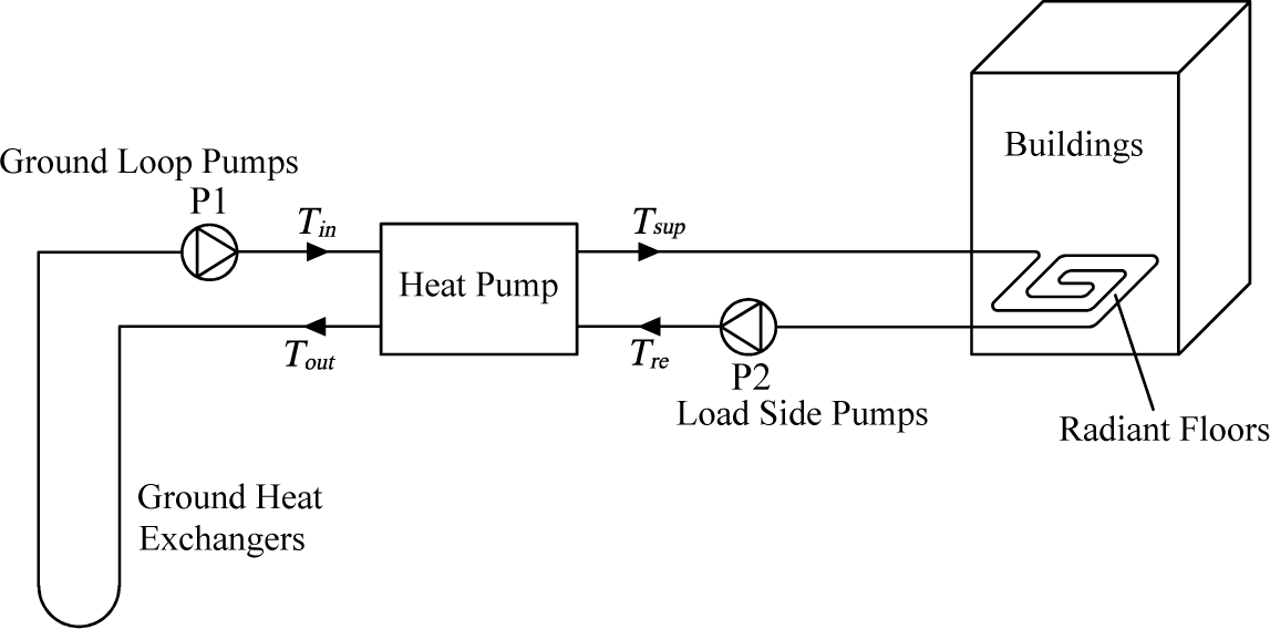
2. System Description

The GCHP heating system under investigation is located in Changsha, the capital of Hunan Province, which has a typical climate characterized by cold winters and hot summers. According to the meteorological parameter statistics of Changsha in the most recent 30 years, the average number of total days in which daily average temperature was below 5 °C during a year was 48. The average relative humidity in the coldest month was up to 83%, which would result in a more intense feeling of cold. The heat pump system supplies heat to two six-storied residential buildings with a total building area of 5420 m2. The heat transfer coefficients of the walls, windows and roofs are all chosen to satisfy the requirements of the China Industry Standard JGJ 134-2010 [18].
A schematic diagram of the system under investigation is shown in Figure 1. Vertical 1.26 inch nominal diameter U-bend ground heat exchangers are installed. Forty 60 m-depth boreholes are arranged around the two buildings. According to the local climate and experience operating other GCHP applications, the circulating water in the ground loop of GCHP systems in South China does not freeze in winter, therefore, water is used as the circulating fluid in the ground loop. The water in the ground loop is circulated through the evaporator of a water-to-water heat pump equipped with a screw compressor, and returns to the GHE after rejecting heat in the evaporator. The heat pump receives heat from the circulating water in the ground loop, and rejects heat in the condenser to the circulating water in the heat distribution system. The heated circulating water is then pumped to the terminals to heat the rooms.
According to the initial scheme, fan coil units would have been used as terminals for both heating and cooling of the two buildings. However, the buildings in Changsha are generally cooling-dominated and therefore reject more heat than they extract over the annual GCHP system operation cycle. Greater ground heat exchanger lengths would be necessary to adequately dissipate the building heat, which would bring about excessive initial cost over the budget. Therefore, the property developer adopted another scheme in which the GCHP system only operates in winter for heating of rooms, and the dispersed room air conditioners operate in summer for cooling of rooms. Floor radiant heating is used for heating of the two buildings to achieve enhanced thermal comfort.

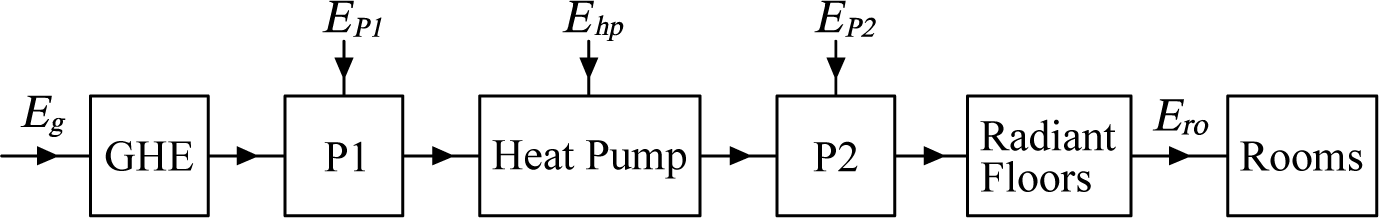
3. Analysis for Exergy Flow and Exergy Efficiency of Each Subsystem

The GCHP system can be divided into four subsystems, which are respectively the ground heat exchange system, heat pump, heat distribution system and terminals. The exergy flows of each subsystem are illustrated in Figure 2. To carry out the analysis, it is assumed that all processes are steady-state and steady flow with negligible potential and kinetic energy effects and no chemical or nuclear reactions. [10,12,13,15]. For a general steady-state and steady flow process, the exergy balance equations are applied to find the exergy loss of each subsystem [19]. Exergy efficiencies often give more revealing insights into process performance than energy efficiencies, and can provide a measure of potential for improvement [20]. The exergy efficiency of each subsystem is defined as the ratio of exergy product rate to exergy input rate [3].

3.1. Ground Heat Exchange System

The ground heat exchange system consists of GHE and ground loop pumps. The exergy input rate from ground can be calculated as:
E g = Q g ( 1 T 0 T g )
Q g = m g c w ( T i n T o u t )
where Eg is the exergy input rate from ground (kW); Qg is the heat extraction rate from ground (kW); T0 is the reference temperature, considered as the outdoor air temperature when the GCHP system operates (K); Tg is ground temperature (K); mg is the mass flow rate of circulating water in ground loop (kg/s); cw is the specific heat of water (kJ/kg·K); Tin and Tout are respectively the inlet and outlet temperatures of the evaporator (K).
The exergy loss of GHE results from the heat exchange between circulating water and ground, and it can be expressed as:
I g = E g + m g c w ( T o u t T i n ) m g c w T 0 ln T o u t T i n
where Ig is the exergy loss of GHE (kW).
The exergy efficiency of ground heat exchange system is calculated as follows:
η g = Q g m g c w T 0 ln T i n T o u t Q g ( 1 T 0 T g ) + E P 1
E P 1 = ϕ P 1 W P 1
where ηg is the exergy efficiency of ground heat exchange system (%); EP1 is the mechanical exergy input rate of ground loop pumps (kW); ϕ P 1 is the motor efficiency of ground loop pumps; WP1 is the electric power of ground loop pumps (kW).

3.2. Heat Pump

The exergy loss of a heat pump consists of the exergy losses of all components in a heat pump. The exergy loss of heat pump is calculated as a whole in this analysis, and is given by:
I h p = E h p + Q g m g c w T 0 ln T i n T o u t [ Q h p m h c w T 0 ln T sup T r e ]
Q h p = m h c w ( T sup T r e )
where Ihp is the exergy loss of heat pump (kW); Ehp is the mechanical exergy input rate of heat pump (kW); Qhp is the heat output of heat pump (kW); mh is the mass flow rate of hot water (kg/s); Tsup and Tre are respectively the supply and return water temperatures of the condenser (K).
The exergy efficiency of heat pump is calculated by:
η h p = Q h p m h c w T 0 ln T sup T r e E h p + Q g m g c w T 0 ln T i n T o u t
E h p = ϕ c o m W h p
where ηhp is the exergy efficiency of heat pump; ϕ c o m is the motor efficiency of screw compressor; Whp is the electric power of heat pump (kW).

3.3. Heat Distribution System

The exergy loss of heat distribution results from the heat loss of network, and can be expressed as:
I h d = γ h d Q h p ( 1 T 0 T sup T r e ln T sup T r e )
where Ihd is the exergy loss of heat distribution (kW); γhd is the heat loss ratio of heat distribution network (%). The total heat distribution distance is as short as 120 m. For simplicity, the heat loss ratio of heat distribution network is taken to be 1.5%.
In view of the small heat loss ratio of heat distribution network, the inlet and outlet water temperatures of terminals are respectively regarded as equal to the supply and return water temperatures of the condenser. The exergy efficiency of heat distribution system is given by:
η h d = Q H ( 1 T 0 T sup T r e ln T sup T r e ) Q h p ( 1 T 0 T sup T r e ln T sup T r e ) + E P 2
Q H = ( 1 γ h d ) Q h p
E P 2 = ϕ P 2 W P 2
where ηhd is the exergy efficiency of heat distribution system (%); QH is the heating load of buildings (kW); EP2 is the mechanical exergy input rate of load side pumps (kW); ϕ P 2 is the motor efficiency of load side pumps; WP2 is the electric power of load side pumps (kW).

3.4. Terminals

The exergy rate transferred to the rooms by terminals is calculated by:
E r o = Q H ( 1 T 0 T a )
The exergy loss of terminals is expressed by:
I t e r = Q H ( 1 T 0 T sup T r e ln T sup T r e ) Q H ( 1 T 0 T a )
where Iter is the exergy loss of terminals (kW); Ta is indoor air temperature (K).
The exergy efficiency of radiant floors is calculated by:
η r f = 1 T 0 T a 1 T 0 T sup T r e ln T sup T r e
where ηrf is the exergy efficiency of radiant floors (%).

4. Results and Discussion

4.1. Test Results

Field tests were performed on 6 January 2013 to acquire operating data for the exergy analysis. The supply and return water temperatures of condenser, the inlet and outlet water temperatures of evaporator, the ground temperature and the air temperature were measured by Pt100 temperature sensors with an uncertainty of ±0.2 °C. The sensor for the measurement of ground temperature is located 30 m under the ground. A paperless recorder based on a single chip microcomputer was used for data acquisition with the aid of temperature sensors.
Water flow rate and electric power were measured, respectively, by ultrasonic flowmeters with an uncertainty of ±1% of actual flow rate and by digital power meters with an uncertainty of ±1% of reading. All parameters were measured when the heat pump operated near steady state condition and near 90% of full load. During the test period, the readings and records fluctuate unobviously. The measured values and calculated values based on measured values for the exergy analysis are listed in Table 1 and Table 2, respectively.

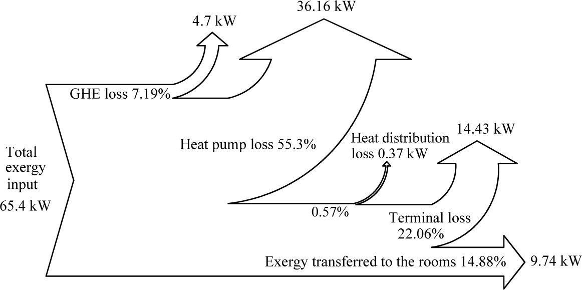
4.2. Exergy Losses and Exergy Efficiencies

The equations in Section 3 and test results were used to calculate the exergy loss and exergy efficiency of each subsystem. The motor efficiencies of the screw compressor and water pumps are respectively 88% and 85%. The exergy rates and their percentages are presented using the Grassmann diagram in Figure 3. The exergy input rate from ground is 7.29 kW. Total exergy input rate consists of the exergy input rate from ground, the mechanical exergy input rates of the heat pump and all water pumps. The largest exergy loss and exergy input rate all occur in the heat pump. The second largest exergy loss occurs in floor heating process. More attention should be paid to the selection of heat pumps and terminals. In view of heat pumps operate under part-load conditions at most time, the heat pumps with relative high COP value under part-load conditions should be preferred.
The exergy efficiencies of the four subsystems are listed in Table 3. The exergy efficiency of the ground heat exchange system is the lowest among the four subsystems. Improving the effectiveness of GHE and reducing the pumping energy for fluid circulation in GHE are all effective measures to improve the exergy efficiency of ground heat exchange systems. In some GCHP heat pump systems, pumps with higher pumping head than needed operate at high flow rate, low temperature difference and low pump efficiency. A proper pumping head should be selected during the system design stage. In addition, variable flow operation of pumps is necessary under part-load operating conditions.
The total exergy efficiency of the GCHP heating system is 14.88% at a reference temperature of 2.8 °C. The total exergy efficiency of the system and COP of the heat pump are compared with those of a GCHP system with horizontal GHE buried in a 1 m depth trench in Ref. [12] and a GCHP system with vertical GHE in Ref. [14], as shown in Table 4. In view of the fact the reference temperatures in Ref. [12] and Ref. [14] are 1 °C and 0 °C, respectively, the total exergy efficiency of the system in this study is also calculated based on the reference temperatures of 1 °C and 0 °C for better comparison.
As seen from Table 4, the total exergy efficiency decreases with the increase of reference temperature. Although the COP of the heat pump in Ref. [12] is lower than that of any other system in Table 4, the total exergy efficiency of the system in Ref. [12] is 36.6% higher than that of the system in this study. Unlike the water-to-water heat pumps in this study and Ref. [14], the heat pump in Ref. [12] is a small water-to-air heat pump. The condenser fan blows across the condenser to disperse the warmed air into the room, which eliminate the existence of terminals and load side pumps. Thus, the total exergy input and total exergy losses are decreased obviously. The total exergy efficiency in this study is 7.3% higher than that of the system in Ref. [14], which can be attributed to relatively higher pumping efficiency and the adoption of radiant floors in this study. The ratio of pumping energy to the heat transferred by pumps (REH) is usually used to evaluate pumping efficiency [21]. The higher REH is, the lower pumping efficiency. The ratio of load side pumping energy to the heat transferred by load side pumps in this study is 0.022, and that in Ref. [14] is up to 0.041. The terminals of the system in Ref. [14] are FCU. The exergy efficiency of FCU is lower than that of radiant floors, which will be discussed in Section 4.3.2 detailly.

4.3. Comparisons between Radiant Floors and FCU

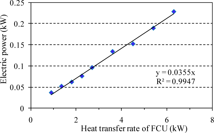
4.3.1. Comparison of the Energy Performance

The energy-saving benefit resulting from the adoption of radiant floors lies in the decrease of heating load. For the rooms with radiant floors, the same body feeling temperature can be achieved even though indoor air temperature is lower than the rooms with other types of terminals. According to China National Standard, GB 50736-2012 [21], the design temperature of the rooms with radiant floors should be 2 °C lower than that of the rooms with other types of terminals. Thus, the indoor air temperature of the rooms with FCU is taken as 19.4 °C. The corresponding decrease of heating load can be deduced from the calculation method of heating load as follows:
Q H = i K i U i A i ( T a T 0 ) + c a ρ ( T a T 0 ) N V 3600
where Ki is temperature correction factors; Ui is the heat transfer coefficient of building envelope (kW/m2·K); Ai is the area of building envelope (m2); N is air exchange rate of rooms (times per hour); ca is the specific heat of air (kJ/kg·K); ρ is air density (kg/m3); V is interior volume of rooms (m3). Above equation indicates that heating load is proportional to indoor and outdoor temperature difference. For the same two buildings in this case, the decrement rate of heating load (DRHL) resulting from the adoption of radiant floors can be calculated as follows:
D R H L = ( 19 . 4 2 . 8 ) ( 17 . 4 2 . 8 ) 19 . 4 2 . 8 = 12 %

4.3.2. Comparison of the Exergetic Performance

To evaluate the exergy efficiency of FCU, it is necessary to find the relationship between the electric power and heat transfer rate of FCU. According to the manufacturer’s catalog data [22], the relationship between the electric power and heat transfer rate of FCU is plotted in Figure 4.
The electric power of FCU is generally linearly related to the heat transfer rate of FCU, and can be calculated by following fitting formula:
W F C U = 0 . 0355 Q F C U ( R 2 = 0 . 9947 )
where WFCU is the electric power of FCU (kW); QFCU is the heat transfer rate of FCU (kW).
If fan coil units were adopted as terminals in this GCHP system, the exergy efficiency of FCU could be calculated by:
η F C U = 1 T 0 T a 1 T 0 T sup T r e ln T sup T r e + 0 . 0355 ϕ F C U
where ηFCU is the exergy efficiency of FCU (%); ϕ F C U is the motor efficiency of FCU and equal to 80%. Suppose that the values of T0, Tsup and Tre are equal to the test results, the exergy efficiency of FCU will be 37.07%. The exergy efficiency of radiant floors is 3.24% higher than that of FCU due to the fact that the radiant floors operate without electric power. If FCU were substituted for the radiant floors in this GCHP heating system in terms of the test results, the total exergy efficiency of system would drop to 13.7%. Besides the advantages in thermal comfort and energy saving compared with FCU, the adoption of radiant floors can bring a certain increase in the total exergy efficiency of system.

5. Conclusions

An exergy analysis of a GCHP system with radiant floors as terminals is performed based on test results. The following concluding remarks can be extracted from this study:
  • The heating load and exergy efficiency of the GCHP heating system with radiant floors are compared with those of the scenario system in which FCU are substituted for the radiant floors. The comparison results show that the adoption of radiant floors can result in a decrease of 12% in heating load, an increase of 3.24% in exergy efficiency of terminals and an increase of 1.18% in total exergy efficiency of system.
  • The analysis results indicate that the largest exergy loss occurs in heat pump, and the second largest exergy loss occurs in terminals. The ground heat exchange system has the lowest exergy efficiency among the four subsystems. Designers of GCHP systems should pay close attention to the selection of heat pumps and terminals, especially to the design of ground heat exchange systems.
  • Both load side pumping energy and source side pumping energy have obvious influence on the energy and exergetic performance of a GCHP heating system. The total exergy efficiency of a GCHP heating system will decrease with the increase of reference temperature.

Acknowledgments

This work was financially supported by Hunan Provincial Natural Science Foundation of China (12JJ9013) and National Natural Science Foundation of China (51276058).

Nomenclature

Ai
area of building envelope (m2)
c
specific heat (kJ/kg·K)
E
exergy (kW)
I
exergy loss (kW)
Ki
temperature correction factors
m
mass flow rate (kg/s)
N
air exchange rate of rooms (times per hour)
Q
heat transfer rate (kW)
T
temperature (K)
Ui
heat transfer coefficient of building envelope (kW/m2·K)
V
interior volume of rooms (m3)
W
electric power (kW)
Greek Letters
η
exergy efficiency (%)
ϕ
motor efficiency (%)
ρ
air density (kg/m3)
γ
heat loss ratio (%)
Subscripts
a
air
com
screw compressor
FCU
fan coil units
g
ground
H
heating
h
hot water
hd
heat distribution
hp
heat pump
in
inlet of the evaporator
out
outlet of the evaporator
P1
ground loop pumps
P2
load side pumps
re
return water
rf
radiant floor
ro
rooms
sup
supply water
ter
terminals
w
water
0
reference environment condition

Author Contributions

Xiao Chen and Xiaoli Hao contributed to the conception of the study, the development of the methodology for exergy analysis and the field tests. Xiao Chen performed the data analyses and wrote the manuscript. Both authors have read and approved the final manuscript.

Conflicts of Interest

The authors declare no conflict of interest.

References

  1. American Society of Heating, Refrigerating and Air-conditioning Engineers (ASHRAE). 2011 ASHRAE Handbook-HVAC Applications; ASHRAE: Atlanta, GA, USA, 2011. [Google Scholar]
  2. Qiu, B.X. Situation and task of developing green and energy-efficient building in China. Proceedings of the 8th International Conference on Green and Energy-efficient Building, Beijing, China, 28–31 March 2012.
  3. Kotas, T.J. The Exergy Method of Thermal Plant Analysis; Paragon Publishing: Trowbridge, UK, 1995. [Google Scholar]
  4. Rosen, M.A.; Dincer, I. Exergy analysis of waste emissions. Int. J. Energy Res. 1999, 23, 1153–1163. [Google Scholar]
  5. Rosen, M.A.; Dincer, I. Thermoeconomic analysis of power plants: An application to a coal-fired electrical generating station. Energy Convers. Manag. 2003, 44, 2743–2761. [Google Scholar]
  6. Rosen, M.A.; Dincer, I.; Kanoglu, M. Role of exergy in increasing efficiency and sustainability and reducing environmental impact. Energy Policy 2008, 36, 128–137. [Google Scholar]
  7. Rosen, M.A. Using exergy to correlate energy research investments and efficiencies: Concept and case studies. Entropy 2013, 15, 262–286. [Google Scholar]
  8. Dincer, I.; Cengel, Y.A. Energy, entropy and exergy concepts and their roles in thermal engineering. Entropy 2001, 3, 116–149. [Google Scholar]
  9. Hammond, G.P. Industrial energy analysis, thermodynamics and sustainability. Appl. Energy 2007, 84, 675–700. [Google Scholar]
  10. Hepbasli, A.; Akdemir, O. Energy and exergy analysis of a ground source (geothermal) heat pump system. Energy Convers. Manag. 2004, 45, 737–753. [Google Scholar]
  11. Ozgener, O.; Hepbasli, A. A parametrical study on the energetic and exergetic assessment of a solar-assisted vertical ground-source heat pump system used for heating a greenhouse. Build. Environ. 2007, 42, 11–24. [Google Scholar]
  12. Esen, H.; Inalli, M.; Esen, M.; Pihtili, K. Energy and exergy analysis of a ground-coupled heat pump system with two horizontal ground heat exchangers. Build. Environ. 2007, 42, 3606–3615. [Google Scholar]
  13. Kuzgunkaya, E.H.; Hepbasli, A. Exergetic performance assessment of a ground-source heat pump drying system. Int. J. Energy Res. 2007, 31, 760–777. [Google Scholar]
  14. Bi, Y.H.; Wang, X.H.; Liu, Y. Comprehensive exergy analysis of a ground-source heat pump system for both building heating and cooling modes. Appl. Energy 2009, 86, 2560–2565. [Google Scholar]
  15. Akpinar, E.K.; Hepbasli, A. A comparative study on exergetic assessment of two ground-source (geothermal) heat pump systems for residential applications. Build. Environ. 2007, 42, 2004–2013. [Google Scholar]
  16. Balta, M.T.; Kalinci, Y.; Hepbasli, A. Evaluating a low exergy heating system from the power plant through the heat pump to the building envelope. Energy Build. 2008, 40, 1799–1804. [Google Scholar]
  17. Xiang, J.Y.; Zhao, J.; Qin, N. Exergetic cost analysis of a space heating system. Energy Build. 2010, 42, 1987–1994. [Google Scholar]
  18. China Industry Standard. Design Standard for Energy Efficiency of Residential Buildings in Hot Summer and Cold Winter Zone, JGJ 134–2010; China Architecture and Building Press: Beijing, China, 2010.
  19. Cengel, Y.; Boles, M.A. Thermodynamics: An Engineering Approach, 4th ed; McGraw-Hill: New York, NY, USA, 2001. [Google Scholar]
  20. Hernández-Román, M.Á.; Manzano-Ramírez, A.; Pineda-Piñón, J.; Ortega-Moody, J. Exergetic and thermoeconomic analyses of solar air heating processes using a parabolic trough collector. Entropy 2014, 16, 4612–4625. [Google Scholar]
  21. China National Standard. Design Standard for Heating Ventilation and Air Conditioning of Civil Buildings, GB 50736–2012; China Architecture and Building Press: Beijing, China, 2012.
  22. Carrier China Limited. Manufacturer Data of Fan Coil Units; Shanghai, China, 2011. [Google Scholar]
Figure 1. Schematic diagram of the GCHP system.
Entropy 17 02328f1
Figure 2. Exergy flows in the GCHP system with radiant floors.
Entropy 17 02328f2
Figure 3. Grassmann diagram of the GCHP system.
Entropy 17 02328f3
Figure 4. Electric power versus heat transfer rate of FCU.
Entropy 17 02328f4
Table 1. The average values of measured parameters.
Measured ParametersAverage Value
Inlet temperature of the evaporator (°C)9.2
Outlet temperature of the evaporator (°C)6.1
Supply water temperature of the condenser (°C)44.2
Return water temperature of the condenser (°C)40
Flow rate of the circulating water in GHE (m3/h)41.6
Flow rate of the hot water (m3/h)40.3
Electric power of the heat pump (kW)58.1
COP (Coeffient of Performance) of the heat pump3.39
Electric power of the ground loop pumps (kW)3.8
Electric power of the load side pumps (kW)4.4
Ground temperature (°C)16.9
Average outdoor air temperature (°C)2.8
Average indoor air temperature (°C)17.4
Table 2. The calculated values based on measured values.
ParametersCalculated Value
Heat output of heat pump (kW)195.7
Heat extraction rate from ground (kW)150
COP (Coeffient of Performance) of the heat pump3.39
Heating load of the buildings (kW)192.8
Heat loss rate of heat distribution network (kW)2.9
Table 3. Exergy efficiencies of the four subsystems.
SubsystemsExergy Efficiency (%)
Ground heat exchange system24.63
Heat pump45.66
Heat distribution system85.47
Terminals (Radiant floors)40.31
Table 4. Comparisons of total exergy efficiency and COP of heat pump.
COP of Heat PumpTotal Exergy Efficiencies at Different Reference Temperature (%)
2.8 °C1 °C0 °C

Ref. [12]2.553.1
Ref. [13]3.910.0
This study3.3914.8816.517.3

